US8323778B2 - Environmentally resilient corrugated building products and methods of manufacture - Google Patents
Environmentally resilient corrugated building products and methods of manufacture Download PDFInfo
- Publication number
- US8323778B2 US8323778B2 US11/035,548 US3554805A US8323778B2 US 8323778 B2 US8323778 B2 US 8323778B2 US 3554805 A US3554805 A US 3554805A US 8323778 B2 US8323778 B2 US 8323778B2
- Authority
- US
- United States
- Prior art keywords
- sheet
- vinyl
- substrate
- panel
- metallic
- Prior art date
- Legal status (The legal status is an assumption and is not a legal conclusion. Google has not performed a legal analysis and makes no representation as to the accuracy of the status listed.)
- Expired - Fee Related, expires
Links
Images


Classifications
-
- B—PERFORMING OPERATIONS; TRANSPORTING
- B32—LAYERED PRODUCTS
- B32B—LAYERED PRODUCTS, i.e. PRODUCTS BUILT-UP OF STRATA OF FLAT OR NON-FLAT, e.g. CELLULAR OR HONEYCOMB, FORM
- B32B15/00—Layered products comprising a layer of metal
- B32B15/04—Layered products comprising a layer of metal comprising metal as the main or only constituent of a layer, which is next to another layer of the same or of a different material
- B32B15/08—Layered products comprising a layer of metal comprising metal as the main or only constituent of a layer, which is next to another layer of the same or of a different material of synthetic resin
- B32B15/082—Layered products comprising a layer of metal comprising metal as the main or only constituent of a layer, which is next to another layer of the same or of a different material of synthetic resin comprising vinyl resins; comprising acrylic resins
-
- B—PERFORMING OPERATIONS; TRANSPORTING
- B32—LAYERED PRODUCTS
- B32B—LAYERED PRODUCTS, i.e. PRODUCTS BUILT-UP OF STRATA OF FLAT OR NON-FLAT, e.g. CELLULAR OR HONEYCOMB, FORM
- B32B15/00—Layered products comprising a layer of metal
- B32B15/18—Layered products comprising a layer of metal comprising iron or steel
-
- B—PERFORMING OPERATIONS; TRANSPORTING
- B32—LAYERED PRODUCTS
- B32B—LAYERED PRODUCTS, i.e. PRODUCTS BUILT-UP OF STRATA OF FLAT OR NON-FLAT, e.g. CELLULAR OR HONEYCOMB, FORM
- B32B3/00—Layered products comprising a layer with external or internal discontinuities or unevennesses, or a layer of non-planar form; Layered products having particular features of form
- B32B3/26—Layered products comprising a layer with external or internal discontinuities or unevennesses, or a layer of non-planar form; Layered products having particular features of form characterised by a particular shape of the outline of the cross-section of a continuous layer; characterised by a layer with cavities or internal voids ; characterised by an apertured layer
- B32B3/28—Layered products comprising a layer with external or internal discontinuities or unevennesses, or a layer of non-planar form; Layered products having particular features of form characterised by a particular shape of the outline of the cross-section of a continuous layer; characterised by a layer with cavities or internal voids ; characterised by an apertured layer characterised by a layer comprising a deformed thin sheet, i.e. the layer having its entire thickness deformed out of the plane, e.g. corrugated, crumpled
-
- E—FIXED CONSTRUCTIONS
- E04—BUILDING
- E04B—GENERAL BUILDING CONSTRUCTIONS; WALLS, e.g. PARTITIONS; ROOFS; FLOORS; CEILINGS; INSULATION OR OTHER PROTECTION OF BUILDINGS
- E04B1/00—Constructions in general; Structures which are not restricted either to walls, e.g. partitions, or floors or ceilings or roofs
- E04B1/02—Structures consisting primarily of load-supporting, block-shaped, or slab-shaped elements
- E04B1/08—Structures consisting primarily of load-supporting, block-shaped, or slab-shaped elements the elements consisting of metal
-
- E—FIXED CONSTRUCTIONS
- E04—BUILDING
- E04C—STRUCTURAL ELEMENTS; BUILDING MATERIALS
- E04C2/00—Building elements of relatively thin form for the construction of parts of buildings, e.g. sheet materials, slabs, or panels
- E04C2/02—Building elements of relatively thin form for the construction of parts of buildings, e.g. sheet materials, slabs, or panels characterised by specified materials
- E04C2/08—Building elements of relatively thin form for the construction of parts of buildings, e.g. sheet materials, slabs, or panels characterised by specified materials of metal, e.g. sheet metal
-
- E—FIXED CONSTRUCTIONS
- E04—BUILDING
- E04C—STRUCTURAL ELEMENTS; BUILDING MATERIALS
- E04C2/00—Building elements of relatively thin form for the construction of parts of buildings, e.g. sheet materials, slabs, or panels
- E04C2/02—Building elements of relatively thin form for the construction of parts of buildings, e.g. sheet materials, slabs, or panels characterised by specified materials
- E04C2/26—Building elements of relatively thin form for the construction of parts of buildings, e.g. sheet materials, slabs, or panels characterised by specified materials composed of materials covered by two or more of groups E04C2/04, E04C2/08, E04C2/10 or of materials covered by one of these groups with a material not specified in one of the groups
-
- E—FIXED CONSTRUCTIONS
- E04—BUILDING
- E04C—STRUCTURAL ELEMENTS; BUILDING MATERIALS
- E04C2/00—Building elements of relatively thin form for the construction of parts of buildings, e.g. sheet materials, slabs, or panels
- E04C2/30—Building elements of relatively thin form for the construction of parts of buildings, e.g. sheet materials, slabs, or panels characterised by the shape or structure
- E04C2/32—Building elements of relatively thin form for the construction of parts of buildings, e.g. sheet materials, slabs, or panels characterised by the shape or structure formed of corrugated or otherwise indented sheet-like material; composed of such layers with or without layers of flat sheet-like material
- E04C2/322—Building elements of relatively thin form for the construction of parts of buildings, e.g. sheet materials, slabs, or panels characterised by the shape or structure formed of corrugated or otherwise indented sheet-like material; composed of such layers with or without layers of flat sheet-like material with parallel corrugations
-
- B—PERFORMING OPERATIONS; TRANSPORTING
- B32—LAYERED PRODUCTS
- B32B—LAYERED PRODUCTS, i.e. PRODUCTS BUILT-UP OF STRATA OF FLAT OR NON-FLAT, e.g. CELLULAR OR HONEYCOMB, FORM
- B32B2250/00—Layers arrangement
- B32B2250/02—2 layers
-
- B—PERFORMING OPERATIONS; TRANSPORTING
- B32—LAYERED PRODUCTS
- B32B—LAYERED PRODUCTS, i.e. PRODUCTS BUILT-UP OF STRATA OF FLAT OR NON-FLAT, e.g. CELLULAR OR HONEYCOMB, FORM
- B32B2307/00—Properties of the layers or laminate
- B32B2307/40—Properties of the layers or laminate having particular optical properties
- B32B2307/402—Coloured
- B32B2307/4026—Coloured within the layer by addition of a colorant, e.g. pigments, dyes
-
- B—PERFORMING OPERATIONS; TRANSPORTING
- B32—LAYERED PRODUCTS
- B32B—LAYERED PRODUCTS, i.e. PRODUCTS BUILT-UP OF STRATA OF FLAT OR NON-FLAT, e.g. CELLULAR OR HONEYCOMB, FORM
- B32B2307/00—Properties of the layers or laminate
- B32B2307/70—Other properties
- B32B2307/71—Resistive to light or to UV
-
- B—PERFORMING OPERATIONS; TRANSPORTING
- B32—LAYERED PRODUCTS
- B32B—LAYERED PRODUCTS, i.e. PRODUCTS BUILT-UP OF STRATA OF FLAT OR NON-FLAT, e.g. CELLULAR OR HONEYCOMB, FORM
- B32B2419/00—Buildings or parts thereof
-
- Y—GENERAL TAGGING OF NEW TECHNOLOGICAL DEVELOPMENTS; GENERAL TAGGING OF CROSS-SECTIONAL TECHNOLOGIES SPANNING OVER SEVERAL SECTIONS OF THE IPC; TECHNICAL SUBJECTS COVERED BY FORMER USPC CROSS-REFERENCE ART COLLECTIONS [XRACs] AND DIGESTS
- Y10—TECHNICAL SUBJECTS COVERED BY FORMER USPC
- Y10T—TECHNICAL SUBJECTS COVERED BY FORMER US CLASSIFICATION
- Y10T156/00—Adhesive bonding and miscellaneous chemical manufacture
- Y10T156/10—Methods of surface bonding and/or assembly therefor
-
- Y—GENERAL TAGGING OF NEW TECHNOLOGICAL DEVELOPMENTS; GENERAL TAGGING OF CROSS-SECTIONAL TECHNOLOGIES SPANNING OVER SEVERAL SECTIONS OF THE IPC; TECHNICAL SUBJECTS COVERED BY FORMER USPC CROSS-REFERENCE ART COLLECTIONS [XRACs] AND DIGESTS
- Y10—TECHNICAL SUBJECTS COVERED BY FORMER USPC
- Y10T—TECHNICAL SUBJECTS COVERED BY FORMER US CLASSIFICATION
- Y10T29/00—Metal working
- Y10T29/49—Method of mechanical manufacture
- Y10T29/49826—Assembling or joining
- Y10T29/49906—Metal deforming with nonmetallic bonding
-
- Y—GENERAL TAGGING OF NEW TECHNOLOGICAL DEVELOPMENTS; GENERAL TAGGING OF CROSS-SECTIONAL TECHNOLOGIES SPANNING OVER SEVERAL SECTIONS OF THE IPC; TECHNICAL SUBJECTS COVERED BY FORMER USPC CROSS-REFERENCE ART COLLECTIONS [XRACs] AND DIGESTS
- Y10—TECHNICAL SUBJECTS COVERED BY FORMER USPC
- Y10T—TECHNICAL SUBJECTS COVERED BY FORMER US CLASSIFICATION
- Y10T428/00—Stock material or miscellaneous articles
- Y10T428/24—Structurally defined web or sheet [e.g., overall dimension, etc.]
- Y10T428/24479—Structurally defined web or sheet [e.g., overall dimension, etc.] including variation in thickness
- Y10T428/24521—Structurally defined web or sheet [e.g., overall dimension, etc.] including variation in thickness with component conforming to contour of nonplanar surface
- Y10T428/24537—Parallel ribs and/or grooves
-
- Y—GENERAL TAGGING OF NEW TECHNOLOGICAL DEVELOPMENTS; GENERAL TAGGING OF CROSS-SECTIONAL TECHNOLOGIES SPANNING OVER SEVERAL SECTIONS OF THE IPC; TECHNICAL SUBJECTS COVERED BY FORMER USPC CROSS-REFERENCE ART COLLECTIONS [XRACs] AND DIGESTS
- Y10—TECHNICAL SUBJECTS COVERED BY FORMER USPC
- Y10T—TECHNICAL SUBJECTS COVERED BY FORMER US CLASSIFICATION
- Y10T428/00—Stock material or miscellaneous articles
- Y10T428/24—Structurally defined web or sheet [e.g., overall dimension, etc.]
- Y10T428/24479—Structurally defined web or sheet [e.g., overall dimension, etc.] including variation in thickness
- Y10T428/24521—Structurally defined web or sheet [e.g., overall dimension, etc.] including variation in thickness with component conforming to contour of nonplanar surface
- Y10T428/24545—Containing metal or metal compound
-
- Y—GENERAL TAGGING OF NEW TECHNOLOGICAL DEVELOPMENTS; GENERAL TAGGING OF CROSS-SECTIONAL TECHNOLOGIES SPANNING OVER SEVERAL SECTIONS OF THE IPC; TECHNICAL SUBJECTS COVERED BY FORMER USPC CROSS-REFERENCE ART COLLECTIONS [XRACs] AND DIGESTS
- Y10—TECHNICAL SUBJECTS COVERED BY FORMER USPC
- Y10T—TECHNICAL SUBJECTS COVERED BY FORMER US CLASSIFICATION
- Y10T428/00—Stock material or miscellaneous articles
- Y10T428/24—Structurally defined web or sheet [e.g., overall dimension, etc.]
- Y10T428/24479—Structurally defined web or sheet [e.g., overall dimension, etc.] including variation in thickness
- Y10T428/2457—Parallel ribs and/or grooves
-
- Y—GENERAL TAGGING OF NEW TECHNOLOGICAL DEVELOPMENTS; GENERAL TAGGING OF CROSS-SECTIONAL TECHNOLOGIES SPANNING OVER SEVERAL SECTIONS OF THE IPC; TECHNICAL SUBJECTS COVERED BY FORMER USPC CROSS-REFERENCE ART COLLECTIONS [XRACs] AND DIGESTS
- Y10—TECHNICAL SUBJECTS COVERED BY FORMER USPC
- Y10T—TECHNICAL SUBJECTS COVERED BY FORMER US CLASSIFICATION
- Y10T428/00—Stock material or miscellaneous articles
- Y10T428/24—Structurally defined web or sheet [e.g., overall dimension, etc.]
- Y10T428/24628—Nonplanar uniform thickness material
- Y10T428/24669—Aligned or parallel nonplanarities
- Y10T428/24694—Parallel corrugations
- Y10T428/24711—Plural corrugated components
-
- Y—GENERAL TAGGING OF NEW TECHNOLOGICAL DEVELOPMENTS; GENERAL TAGGING OF CROSS-SECTIONAL TECHNOLOGIES SPANNING OVER SEVERAL SECTIONS OF THE IPC; TECHNICAL SUBJECTS COVERED BY FORMER USPC CROSS-REFERENCE ART COLLECTIONS [XRACs] AND DIGESTS
- Y10—TECHNICAL SUBJECTS COVERED BY FORMER USPC
- Y10T—TECHNICAL SUBJECTS COVERED BY FORMER US CLASSIFICATION
- Y10T428/00—Stock material or miscellaneous articles
- Y10T428/31504—Composite [nonstructural laminate]
- Y10T428/31678—Of metal
- Y10T428/31692—Next to addition polymer from unsaturated monomers
Definitions
- the present disclosure is generally related to building products and, more particularly, is related to products and manufacturing methods for environmentally resilient building products.
- Sheet metal generally possesses a high tensile strength, but is often very flexible. For structural purposes, the flexibility can be reduced through the use of additional structure attached to the sheet metal, such as beams, purlins, bars, and posts, among others. Additional structural components, however, increase the cost for the additional materials and increase the size and weight of the assembled component.
- corrugating is known to produce metal sheet products with significantly reduced flexibility along at least one axis.
- corrugating machines also referred to as roll forming machines have been developed to provide corrugation to flat sheet metal in a continuous process.
- An example of the prior art relating to roll forming machines can be found in U.S. Pat. No. 4,269,055, which is hereby incorporated by reference in its entirety.
- Metal sheets are often used in applications where specific aesthetic properties are desirable on at least one surface of the metal sheet.
- the aesthetic property may constitute a specific color.
- Methods for applying a solid color to corrugated metallic products have previously been performed using spraying or coating processes 100 , as illustrated in FIG. 1 .
- the flat metallic product 110 is unrolled from a coil 102 and made proximate to, for example, spray nozzles 120 , which deliver a sprayed paint or coating 130 to the surface of the flat metallic product 110 .
- the flat metallic product is dried or cured using, for example, a heater or oven 140 and then rolled into a coil 104 .
- Other cases may require specific graphical images or patterns in lieu of a solid color.
- Some methods of applying a graphical image or pattern to flat metallic product include immersion graphics methods where, for example, an inked film is applied to the flat metallic product, which is then immersed to dissolve the film, leaving the ink image or pattern on the flat metallic product.
- immersion graphics products may not provide a surface that is sufficiently resistant to scratching, abrasion, weathering, or fading due to outdoor exposure or mechanical impact associated with subsequent processing, assembly, or use.
- the laminating process 200 in this context includes adhesively bonding a graphic film 202 to at least one surface of a flat metallic sheet 201 .
- the graphic film 202 may be applied using the pressure of a laminating roll 220 .
- the laminating roll 220 may possess specific surface properties which are transferred or embossed into the surface of the graphic film 202 during application.
- the resulting laminated metallic sheet 210 includes a graphic film 202 , which may possess specific aesthetic properties including solid colors, metallic finishes, patterns, and graphical images.
- the graphic film 202 may possess specific surface finish properties such as brushed, matte, or pebbled, among others.
- This process has only been applicable to flat products because the manufacturing impracticality of continuously processing laminated corrugated products. For example, previous attempts to corrugate a laminated sheet have resulted in a graphic film that weakens and cracks during subsequent processing and is not resistant to damaging elements associated with an outdoor environment.
- Embodiments of the present disclosure provide an environmentally resilient structural product, comprising: a vinyl laminate and a formed-sheet metallic substrate having a first side; wherein the vinyl laminate is adhesively attached to the first side.
- an environmentally resilient outdoor building comprising: at least one formed-sheet metallic panel, the panel comprising a vinyl layer, and a corrugated metallic substrate having a first side, wherein the vinyl layer is bonded to the first side.
- Embodiments of the present disclosure can also be viewed as methods for providing a decorative, environmentally resilient, structurally significant panel.
- one embodiment of such a method can be broadly summarized by the following steps: bonding a first side of a vinyl layer to a first side of a flat metallic sheet; and deforming the flat metallic sheet to create a plurality of parallel ribs in the first side of the metallic sheet.
- FIG. 1 is a side view of a coating/painting process for metal products as is known in the prior art.
- FIG. 2 is a side view of a process of applying a laminate to flat metallic sheet as is known in the prior art.
- FIG. 3 is an illustration of a side-elevational view of an exemplary roll former used in an embodiment, as disclosed herein.
- FIG. 4 is an illustration of a partial top view of the exemplary roll former of FIG. 3 used in an embodiment, as disclosed herein.
- FIG. 5 is an illustration of a partial end view of a set of complementary rollers and a partial cross-sectional view of a vinyl laminated metallic sheet of the exemplary roll former of FIG. 3 used in an embodiment, as disclosed herein.
- FIG. 6 is a side cross-sectional view of a flat metallic sheet with a vinyl laminate.
- FIG. 7 is an end cross-sectional view of a vinyl-laminated corrugated metal sheet, as disclosed herein.
- FIG. 8 is an illustration of side-elevational view of an exemplary roll former used in an embodiment, as disclosed herein.
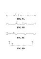
- FIGS. 9A-9D are end cross-sectional views of exemplary formed-sheet vinyl laminated metallic products, as disclosed herein.
- FIG. 10 is a block diagram of an exemplary method of producing environmentally resilient products as disclosed herein.
- FIG. 11 is a perspective view of an exemplary building constructed using environmentally resilient corrugated metallic products, as disclosed herein.
- FIG. 3 illustrates a side-elevational view of an exemplary roll former used in an embodiment, as disclosed herein.
- the roll former 300 begins with a vinyl laminated flat metallic sheet 305 , as manufactured in a device consistent with the prior art, as discussed in reference to FIG. 2 addressed in the preceding Background section.
- the vinyl laminated flat metallic sheet 305 of FIG. 3 retains a carrier film (not shown) associated with the vinyl laminating material.
- the vinyl laminated flat metallic sheet 305 is propelled in direction A and drawn between a first set of complementary forming rollers 322 and 323 to form a first set of channels/ridges, creating a partially formed sheet 306 .
- the partially formed sheet 306 is propelled from the first set of complementary forming rollers 322 and 323 and drawn between a second set of complementary rollers 324 and 325 .
- the second complementary forming rollers 324 and 325 form additional channels/ridges to create partially formed sheet 307 .
- the partially formed sheet 307 proceeds through complementary forming rollers 326 and 327 to form a final set of channels/ridges such that the corrugated sheet 308 is created.
- the corrugated vinyl laminated metallic sheet 308 is then fed into a shear 340 , where the continuous sheet is cut into panels for subsequent packaging or manufacturing (not shown).
- FIG. 4 illustrates a partial top view of the exemplary forming roller table of FIG. 3 , as discussed above.
- the vinyl laminated flat metallic sheet 305 is propelled in a direction A between a first top forming roller 322 and a first bottom forming roller, which is not visible in this view.
- the partially formed sheet 306 produced by the first complementary forming rollers 322 and 323 has channels/ridges 316 corresponding to the profile of the gap between the first forming rollers 322 and 323 (see FIG. 3 ).
- the partially formed sheet 306 is then drawn into the gap between a second top forming roller 324 and a second bottom forming roller, which is not visible in this view.
- the partially formed sheet 307 produced by the first and second complementary forming rollers 322 , 323 (see FIG. 3 ), 324 , and 325 (see FIG. 3 ) has channels/ridges 317 corresponding to the cumulative profile of the gaps between the two sets of complementary forming rollers 322 , 323 , 324 , and 325 .
- the partially formed sheet 307 is similarly drawn between a third top forming roller 326 and a complementary third bottom forming roller, which is not visible in this view.
- a final set of channels/ridges 318 is formed resulting in a corrugated vinyl laminated metallic sheet 308 .
- the width of the sheet is reduced by the portion of the sheet profile which is deformed to create the depth and height of the channels/ridges, respectively.
- the final corrugated vinyl laminated metallic sheet 308 is not as wide as the vinyl laminated flat metallic sheet 305 that entered the forming roller table 320 .
- roller former 300 configured with any number, combination, or configuration of forming rollers is consistent with this disclosure.
- an alternative roll former 300 may have four or more complementary sets of forming rollers, each configured to produce a single channel or ridge in a vinyl laminated metallic sheet.
- FIG. 5 is an illustration of a partial end view of a set of complementary rollers with a partial cross-sectional view of a vinyl laminated metallic sheet.
- the top forming roller 322 has a complementary profile with the bottom-forming roller 323 .
- the channel/ridge 316 is formed.
- the multiple channels/ridges 316 may be formed by multiple serially arranged forming roller sets configured at specific widths across the vinyl laminated metallic sheet and that the multiple channels/ridges may aggregate to form a corrugated sheet. Further, one of ordinary skill in the art will appreciate that the channels/ridges may have different depths, widths, and shape profiles.
- a roll former is but one way to produce formed-sheet products.
- sheets can be formed using bends, breaks, or folds for introducing the additional dimensional characteristics associated with formed-sheet products.
- a formed-sheet product includes any sheet product subsequently processed to introduced additional dimensional characteristics including products with any number, configuration, or combination of bends, breaks, folds, curls, or rolls.
- FIGS. 6 and 7 illustrate cross-sectional end views of a vinyl laminated flat metallic sheet and a vinyl-laminated corrugated metal sheet, respectively.
- the vinyl laminated flat metallic sheet 600 is formed by a laminating process, such as the process disclosed in the above discussion of FIG. 2 , and includes a vinyl laminate 602 , which has a thickness of at least 0.0005 inches, bonded to at least one side of the flat metallic sheet 601 , which has an exemplary thickness ranging from 10 gauge to 35 gauge.
- the corrugated vinyl laminated metallic sheet 700 of FIG. 7 includes the corrugated metallic substrate 701 and a vinyl layer 702 bonded to at least one side of the corrugated metallic substrate 701 . Additionally, the corrugated vinyl laminated metallic sheet 700 includes multiple parallel channels 710 and ridges 720 .
- the metallic sheets or substrates as disclosed herein may be steel, aluminum, tin, copper, or brass, among others.
- the bonding of the vinyl layer 602 to the metallic sheet 601 is performed on a flat metallic sheet, as previously discussed in reference to FIG. 2 .
- the vinyl laminated flat metallic sheet may be processed using the methods herein to produce the corrugated vinyl laminated metallic sheet.
- the corrugated profile of the product 700 is illustrated as including three primary ribs 720 per section with two secondary ribs 710 between each of the primary ribs 720 , one of ordinary skill in the art knows or will know that the methods herein may be utilized to produce numerous combinations of ribs having various and varied geometric profiles and dimensional characteristics.
- the product 700 also includes a vinyl layer 702 bonded to one side of the metallic sheet 701 .
- the vinyl layer 702 which has a thickness of at least 0.0005 inches, is UV-stabilized and provides an ultra-violet light resistant protective covering for the metallic sheet 701 . Additionally, the product 700 provides a vinyl layer 702 that is resistant to delamination. The vinyl layer 702 also provides a decorative finish for the product 700 .
- the vinyl layer 702 may have solid color or some graphical representation. Exemplary graphical representations include, but are not limited to, metallic finishes such as gold or silver including different textures such as brushed, matte, pebbled, or gloss, among others. Other exemplary graphical representations include, but are not limited to, natural finishes such as wood grain or an outdoor environment blending pattern such as, for example, one sold under the registered trademark, REALTREE®.
- FIG. 8 illustrates a side-elevational view of an exemplary roll former used in an embodiment, as disclosed herein.
- the roll former 800 begins with a vinyl laminated flat metallic sheet 805 , as manufactured in a device consistent with the prior art, as previously discussed in reference to FIG. 2 .
- the vinyl layer 815 of the vinyl laminated flat metallic sheet 805 includes a carrier film 832 , that may be removed from the vinyl laminated flat metallic sheet 805 or it may be left in place during the forming operation. If the carrier film 832 is removed before the vinyl laminated flat metallic sheet 805 enters the forming roller table 820 , the carrier film is wound onto a separate roll 830 .
- both sides of the vinyl laminated flat metallic sheet may have a vinyl laminate applied.
- the removal of a second carrier film may be performed prior to the roll forming process or the second carrier film may remain attached during subsequent processing.
- the vinyl laminated flat metallic sheet 806 is drawn between a first set of complementary forming rollers 822 and 823 to form a first set of channels/ridges, creating a partially formed sheet 806 .
- the partially formed sheet 806 is propelled from the first set of complementary forming rollers 822 and 823 and drawn between a second set of complementary rollers 824 and 825 .
- the second set of complementary forming rollers 824 and 825 forms additional channels/ridges to create partially formed sheet 807 .
- the partially formed sheet 807 proceeds through complementary forming rollers 826 and 827 to form another set of ridges/channels such that the corrugated sheet 808 is produced without the carrier film 832 .
- the roll forming process may be performed by four or more sets of forming rollers, each configured to generate an element of the overall profile.
- the corrugated vinyl laminated metallic sheet 808 may then be fed into a shear 840 , where the continuous sheet is cut into panels for subsequent packaging or manufacturing (not shown). Additionally, excess vinyl laminate may be trimmed at one or more of numerous different stages of the manufacturing. For example, the vinyl laminate may be trimmed before or after the roll forming 820 or before, after, or during the shear function 840 .
- FIGS. 9A-9D illustrate end cross-sectional views of exemplary formed-sheet vinyl laminated metallic products, as disclosed herein.
- the exemplary profile of FIG. 9A includes five primary ribs 902 , each separated by two wide, shallow ribs 904 .
- the exemplary profile of FIG. 19B similarly includes four primary ribs 912 , each separated by two wide, shallow ribs 914 .
- the primary ribs 912 of FIG. 9B illustrate a different geometrical and dimensional profile than the primary ribs 902 of FIG. 9A .
- the exemplary profile of FIG. 9C similarly includes four primary channels 922 , each separated by two wide, shallow channels 924 .
- the exemplary profile illustrated in FIG. 9D includes four wide, shallow channels 932 , one standing seam locking surface 934 , and one standing seam locking tab 936 .
- FIG. 10 is a block diagram of an exemplary method of producing environmentally resilient products, as disclosed herein.
- the method 1000 first bonds a vinyl layer to a flat metallic sheet in step 1010 .
- step 1020 constitutes removing the carrier film component of the vinyl layer.
- the vinyl laminated flat metallic sheet is deformed using, for example, a roll forming device, to produce channels/ridges in block 1030 .
- block 1040 the excess vinyl material is trimmed from the edges of the metallic sheet, if present. This step may be optionally performed before or after the deforming step.
- FIG. 11 illustrates a perspective view of an exemplary building constructed using environmentally resilient corrugated products, as disclosed herein.
- the building 1100 may be fully or partially constructed utilizing corrugated vinyl laminated metallic wall panels 1110 consistent with the disclosure herein.
- Corrugated vinyl laminated metallic wall panels 1110 may be produced from metallic substrate in the exemplary thickness range from 18 gauge to 30 gauge.
- the vinyl laminated panels are environmentally resilient.
- the building 1100 may also utilize one or more corrugated vinyl laminated metallic roof panels 1120 for all or part of the roof.
- Corrugated vinyl laminated metallic roof panels 1120 may be produced from metallic substrate in the exemplary thickness range from 18 gauge to 30 gauge.
Abstract
An environmentally resilient building product of a vinyl laminated formed-sheet metallic substrate wherein the vinyl laminate is adhesively attached to the formed-sheet metallic substrate to provide a durable and attractive surface. Possible decorative and resilient surfaces include, but are not limited to solid colors, metallic finishes, and graphical images or patterns, all available in a variety of textures.
Description
The present disclosure is generally related to building products and, more particularly, is related to products and manufacturing methods for environmentally resilient building products.
Many different products have utilized, and continue to utilize, sheet metal as a raw material for constructing various components. Sheet metal generally possesses a high tensile strength, but is often very flexible. For structural purposes, the flexibility can be reduced through the use of additional structure attached to the sheet metal, such as beams, purlins, bars, and posts, among others. Additional structural components, however, increase the cost for the additional materials and increase the size and weight of the assembled component.
One method for avoiding the requirement for additional structure is to break or bend the sheet along a line where the reduction in flexibility is desired. When done as a series of parallel bends to form channels or ridges, this is known as corrugating. Corrugating is known to produce metal sheet products with significantly reduced flexibility along at least one axis. Although the corrugation may be produced by performing a series of independent breaks on a metal sheet, corrugating machines also referred to as roll forming machines have been developed to provide corrugation to flat sheet metal in a continuous process. An example of the prior art relating to roll forming machines can be found in U.S. Pat. No. 4,269,055, which is hereby incorporated by reference in its entirety.
Metal sheets are often used in applications where specific aesthetic properties are desirable on at least one surface of the metal sheet. In some cases, the aesthetic property may constitute a specific color. Methods for applying a solid color to corrugated metallic products have previously been performed using spraying or coating processes 100, as illustrated in FIG. 1 . Referring to FIG. 1 , the flat metallic product 110 is unrolled from a coil 102 and made proximate to, for example, spray nozzles 120, which deliver a sprayed paint or coating 130 to the surface of the flat metallic product 110. After coating or painting, the flat metallic product is dried or cured using, for example, a heater or oven 140 and then rolled into a coil 104. Other cases may require specific graphical images or patterns in lieu of a solid color. Some methods of applying a graphical image or pattern to flat metallic product include immersion graphics methods where, for example, an inked film is applied to the flat metallic product, which is then immersed to dissolve the film, leaving the ink image or pattern on the flat metallic product. Like the painted coating products discussed above, the immersion graphics products may not provide a surface that is sufficiently resistant to scratching, abrasion, weathering, or fading due to outdoor exposure or mechanical impact associated with subsequent processing, assembly, or use.
One technique for providing mechanically resilient protection for metallic sheet products includes laminating. The laminating process 200 in this context, as illustrated in FIG. 2 , includes adhesively bonding a graphic film 202 to at least one surface of a flat metallic sheet 201. By way of example, the graphic film 202 may be applied using the pressure of a laminating roll 220. Additionally, the laminating roll 220 may possess specific surface properties which are transferred or embossed into the surface of the graphic film 202 during application. The resulting laminated metallic sheet 210 includes a graphic film 202, which may possess specific aesthetic properties including solid colors, metallic finishes, patterns, and graphical images. Additionally, if embossing was performed, the graphic film 202 may possess specific surface finish properties such as brushed, matte, or pebbled, among others. This process, however, has only been applicable to flat products because the manufacturing impracticality of continuously processing laminated corrugated products. For example, previous attempts to corrugate a laminated sheet have resulted in a graphic film that weakens and cracks during subsequent processing and is not resistant to damaging elements associated with an outdoor environment.
Thus, a heretofore-unaddressed need exists in the industry to address the aforementioned deficiencies and inadequacies.
Embodiments of the present disclosure provide an environmentally resilient structural product, comprising: a vinyl laminate and a formed-sheet metallic substrate having a first side; wherein the vinyl laminate is adhesively attached to the first side.
Briefly described, other embodiments of the present disclosure provide an environmentally resilient outdoor building, comprising: at least one formed-sheet metallic panel, the panel comprising a vinyl layer, and a corrugated metallic substrate having a first side, wherein the vinyl layer is bonded to the first side.
Embodiments of the present disclosure can also be viewed as methods for providing a decorative, environmentally resilient, structurally significant panel. In this regard, one embodiment of such a method, among others, can be broadly summarized by the following steps: bonding a first side of a vinyl layer to a first side of a flat metallic sheet; and deforming the flat metallic sheet to create a plurality of parallel ribs in the first side of the metallic sheet.
Other systems, methods, features, and advantages of the present disclosure will be or become apparent to one with skill in the art upon examination of the following drawings and detailed description. It is intended that all such additional systems, methods, features, and advantages be included within this description, be within the scope of the present disclosure, and be protected by the accompanying claims.
Many aspects of the disclosure can be better understood with reference to the following drawings. The components in the drawings are not necessarily to scale, emphasis instead being placed upon clearly illustrating the principles of the present disclosure. Moreover, in the drawings, like reference numerals designate corresponding parts throughout the several views.
Reference is now made in detail to the description of the embodiments as illustrated in the drawings. While several embodiments are described in connection with these drawings, there is no intent to limit the invention to the embodiment or embodiments disclosed herein. On the contrary, the intent is to cover all alternatives, modifications, and equivalents.
Reference is made to FIG. 3 , which illustrates a side-elevational view of an exemplary roll former used in an embodiment, as disclosed herein. The roll former 300 begins with a vinyl laminated flat metallic sheet 305, as manufactured in a device consistent with the prior art, as discussed in reference to FIG. 2 addressed in the preceding Background section. The vinyl laminated flat metallic sheet 305 of FIG. 3 retains a carrier film (not shown) associated with the vinyl laminating material. The vinyl laminated flat metallic sheet 305 is propelled in direction A and drawn between a first set of complementary forming rollers 322 and 323 to form a first set of channels/ridges, creating a partially formed sheet 306. The partially formed sheet 306 is propelled from the first set of complementary forming rollers 322 and 323 and drawn between a second set of complementary rollers 324 and 325. The second complementary forming rollers 324 and 325 form additional channels/ridges to create partially formed sheet 307. Similarly, the partially formed sheet 307 proceeds through complementary forming rollers 326 and 327 to form a final set of channels/ridges such that the corrugated sheet 308 is created. The corrugated vinyl laminated metallic sheet 308 is then fed into a shear 340, where the continuous sheet is cut into panels for subsequent packaging or manufacturing (not shown).
Reference is now made to FIG. 4 , which illustrates a partial top view of the exemplary forming roller table of FIG. 3 , as discussed above. The vinyl laminated flat metallic sheet 305 is propelled in a direction A between a first top forming roller 322 and a first bottom forming roller, which is not visible in this view. The partially formed sheet 306 produced by the first complementary forming rollers 322 and 323 (see FIG. 3 ) has channels/ridges 316 corresponding to the profile of the gap between the first forming rollers 322 and 323 (see FIG. 3 ). The partially formed sheet 306 is then drawn into the gap between a second top forming roller 324 and a second bottom forming roller, which is not visible in this view. The partially formed sheet 307 produced by the first and second complementary forming rollers 322, 323 (see FIG. 3 ), 324, and 325 (see FIG. 3 ) has channels/ridges 317 corresponding to the cumulative profile of the gaps between the two sets of complementary forming rollers 322, 323, 324, and 325.
The partially formed sheet 307 is similarly drawn between a third top forming roller 326 and a complementary third bottom forming roller, which is not visible in this view. A final set of channels/ridges 318 is formed resulting in a corrugated vinyl laminated metallic sheet 308. Note that as the vinyl laminated metallic sheet progresses through each of the sets of complementary forming rollers, the width of the sheet is reduced by the portion of the sheet profile which is deformed to create the depth and height of the channels/ridges, respectively. In other words, the final corrugated vinyl laminated metallic sheet 308 is not as wide as the vinyl laminated flat metallic sheet 305 that entered the forming roller table 320. One of ordinary skill in the art knows, or will know, that the complementary forming roller configurations of FIGS. 3 and 4 are merely exemplary and that a roll former 300 configured with any number, combination, or configuration of forming rollers is consistent with this disclosure. For example, an alternative roll former 300 may have four or more complementary sets of forming rollers, each configured to produce a single channel or ridge in a vinyl laminated metallic sheet.
Reference is briefly made to FIG. 5 , which is an illustration of a partial end view of a set of complementary rollers with a partial cross-sectional view of a vinyl laminated metallic sheet. As discussed above, the top forming roller 322 has a complementary profile with the bottom-forming roller 323. As the vinyl laminated metallic sheet 306 is drawn through the gap between the two forming rollers 322 and 323, the channel/ridge 316 is formed. One of ordinary skill in the art knows or will know that the multiple channels/ridges 316 may be formed by multiple serially arranged forming roller sets configured at specific widths across the vinyl laminated metallic sheet and that the multiple channels/ridges may aggregate to form a corrugated sheet. Further, one of ordinary skill in the art will appreciate that the channels/ridges may have different depths, widths, and shape profiles.
Further, one of ordinary skill in the art will appreciate that a roll former is but one way to produce formed-sheet products. For example, in addition to roll forming, sheets can be formed using bends, breaks, or folds for introducing the additional dimensional characteristics associated with formed-sheet products. Additionally, one of ordinary skill in the art knows or will know that a formed-sheet product includes any sheet product subsequently processed to introduced additional dimensional characteristics including products with any number, configuration, or combination of bends, breaks, folds, curls, or rolls.
Reference is now made to FIGS. 6 and 7 , which illustrate cross-sectional end views of a vinyl laminated flat metallic sheet and a vinyl-laminated corrugated metal sheet, respectively. The vinyl laminated flat metallic sheet 600 is formed by a laminating process, such as the process disclosed in the above discussion of FIG. 2 , and includes a vinyl laminate 602, which has a thickness of at least 0.0005 inches, bonded to at least one side of the flat metallic sheet 601, which has an exemplary thickness ranging from 10 gauge to 35 gauge. The corrugated vinyl laminated metallic sheet 700 of FIG. 7 includes the corrugated metallic substrate 701 and a vinyl layer 702 bonded to at least one side of the corrugated metallic substrate 701. Additionally, the corrugated vinyl laminated metallic sheet 700 includes multiple parallel channels 710 and ridges 720. The metallic sheets or substrates as disclosed herein may be steel, aluminum, tin, copper, or brass, among others.
The bonding of the vinyl layer 602 to the metallic sheet 601 is performed on a flat metallic sheet, as previously discussed in reference to FIG. 2 . The vinyl laminated flat metallic sheet may be processed using the methods herein to produce the corrugated vinyl laminated metallic sheet. Although the corrugated profile of the product 700 is illustrated as including three primary ribs 720 per section with two secondary ribs 710 between each of the primary ribs 720, one of ordinary skill in the art knows or will know that the methods herein may be utilized to produce numerous combinations of ribs having various and varied geometric profiles and dimensional characteristics. The product 700 also includes a vinyl layer 702 bonded to one side of the metallic sheet 701. The vinyl layer 702, which has a thickness of at least 0.0005 inches, is UV-stabilized and provides an ultra-violet light resistant protective covering for the metallic sheet 701. Additionally, the product 700 provides a vinyl layer 702 that is resistant to delamination. The vinyl layer 702 also provides a decorative finish for the product 700. For example, the vinyl layer 702 may have solid color or some graphical representation. Exemplary graphical representations include, but are not limited to, metallic finishes such as gold or silver including different textures such as brushed, matte, pebbled, or gloss, among others. Other exemplary graphical representations include, but are not limited to, natural finishes such as wood grain or an outdoor environment blending pattern such as, for example, one sold under the registered trademark, REALTREE®.
Reference is now made to FIG. 8 , which illustrates a side-elevational view of an exemplary roll former used in an embodiment, as disclosed herein. The roll former 800 begins with a vinyl laminated flat metallic sheet 805, as manufactured in a device consistent with the prior art, as previously discussed in reference to FIG. 2 . The vinyl layer 815 of the vinyl laminated flat metallic sheet 805 includes a carrier film 832, that may be removed from the vinyl laminated flat metallic sheet 805 or it may be left in place during the forming operation. If the carrier film 832 is removed before the vinyl laminated flat metallic sheet 805 enters the forming roller table 820, the carrier film is wound onto a separate roll 830. Although, as illustrated, only one side of the vinyl laminated flat metallic sheet is shown as having a vinyl laminate, one of ordinary skill in the art will appreciate that both sides of the vinyl laminated flat metallic sheet may have a vinyl laminate applied. In an embodiment having two sides of vinyl laminate, the removal of a second carrier film may be performed prior to the roll forming process or the second carrier film may remain attached during subsequent processing.
After removing the carrier film 832, the vinyl laminated flat metallic sheet 806 is drawn between a first set of complementary forming rollers 822 and 823 to form a first set of channels/ridges, creating a partially formed sheet 806. The partially formed sheet 806 is propelled from the first set of complementary forming rollers 822 and 823 and drawn between a second set of complementary rollers 824 and 825. The second set of complementary forming rollers 824 and 825 forms additional channels/ridges to create partially formed sheet 807. Similarly, the partially formed sheet 807 proceeds through complementary forming rollers 826 and 827 to form another set of ridges/channels such that the corrugated sheet 808 is produced without the carrier film 832. One of ordinary skill in the art knows or will know that the roll forming process may be performed by four or more sets of forming rollers, each configured to generate an element of the overall profile. The corrugated vinyl laminated metallic sheet 808 may then be fed into a shear 840, where the continuous sheet is cut into panels for subsequent packaging or manufacturing (not shown). Additionally, excess vinyl laminate may be trimmed at one or more of numerous different stages of the manufacturing. For example, the vinyl laminate may be trimmed before or after the roll forming 820 or before, after, or during the shear function 840.
Reference is now made to FIGS. 9A-9D , which illustrate end cross-sectional views of exemplary formed-sheet vinyl laminated metallic products, as disclosed herein. The exemplary profile of FIG. 9A includes five primary ribs 902, each separated by two wide, shallow ribs 904. The exemplary profile of FIG. 19B similarly includes four primary ribs 912, each separated by two wide, shallow ribs 914. As is shown, the primary ribs 912 of FIG. 9B illustrate a different geometrical and dimensional profile than the primary ribs 902 of FIG. 9A . The exemplary profile of FIG. 9C similarly includes four primary channels 922, each separated by two wide, shallow channels 924. The exemplary profile illustrated in FIG. 9D includes four wide, shallow channels 932, one standing seam locking surface 934, and one standing seam locking tab 936.
Reference is now made to FIG. 10 , which is a block diagram of an exemplary method of producing environmentally resilient products, as disclosed herein. The method 1000 first bonds a vinyl layer to a flat metallic sheet in step 1010. Next, optional step 1020 constitutes removing the carrier film component of the vinyl layer. The vinyl laminated flat metallic sheet is deformed using, for example, a roll forming device, to produce channels/ridges in block 1030. In block 1040 the excess vinyl material is trimmed from the edges of the metallic sheet, if present. This step may be optionally performed before or after the deforming step.
Reference is now made to FIG. 11 , which illustrates a perspective view of an exemplary building constructed using environmentally resilient corrugated products, as disclosed herein. The building 1100 may be fully or partially constructed utilizing corrugated vinyl laminated metallic wall panels 1110 consistent with the disclosure herein. Corrugated vinyl laminated metallic wall panels 1110 may be produced from metallic substrate in the exemplary thickness range from 18 gauge to 30 gauge. As discussed above, the vinyl laminated panels are environmentally resilient. Additionally, or in the alternative, the building 1100 may also utilize one or more corrugated vinyl laminated metallic roof panels 1120 for all or part of the roof. Corrugated vinyl laminated metallic roof panels 1120 may be produced from metallic substrate in the exemplary thickness range from 18 gauge to 30 gauge.
It should be emphasized that the above-described embodiments of the present disclosure, particularly, any illustrated embodiments, are merely possible examples of implementations, merely to provide a clear understanding of the principles of the disclosure. Many variations and modifications may be made to the above-described embodiment(s) of the disclosure without departing substantially from the spirit and principles of the disclosure. All such modifications and variations are intended to be included herein within the scope of this disclosure and the present disclosure and protected by the following claims.
Claims (6)
1. An environmentally resilient structural building panel, consisting of:
a piece of vinyl laminate sheet material having a thickness of at least 0.0005 inches; and
a formed-sheet flat metallic substrate having a thickness of between 10 gauge and 35 gauge, inclusively, and having a first side and a second side, the substrate being initially disposed in a continuous sheet in coiled form;
wherein the vinyl laminate comprises a graphical pattern and is adhesively attached to the said first side of the substrate, leaving said second side uncoated, as the substrate is unwound from the coiled form such that the substrate is environmentally resilient, the combined substrate and vinyl laminate sheet material further having a deformation imparted thereto including parallel ribs for strengthening the panel assembly, and a building panel being formed as the substrate is cut to form said building panel after the vinyl laminate has been applied.
2. The panel of claim 1 , wherein the formed-sheet metallic substrate comprises steel.
3. The panel of claim 1 , wherein the vinyl laminate sheet material comprises a resistance to deterioration from a plurality of outdoor elements.
4. The panel of claim 3 , wherein the plurality of outdoor elements is selected from the group comprising: ultra-violet light exposure; precipitation, and a wide range of ambient temperatures.
5. The panel of claim 1 , wherein the vinyl laminate sheet material comprises a resistance to delamination.
6. The panel of claim 1 , wherein the graphical pattern is selected from the group comprising: wood grain; brushed metal; smooth metal; and an outdoor environment blending pattern.
Priority Applications (7)
| Application Number | Priority Date | Filing Date | Title |
|---|---|---|---|
| US11/035,548 US8323778B2 (en) | 2005-01-13 | 2005-01-13 | Environmentally resilient corrugated building products and methods of manufacture |
| CA 2594743 CA2594743A1 (en) | 2005-01-13 | 2006-01-13 | Environmentally resilient corrugated building products and methods of manufacture |
| EP06718321A EP1836357A4 (en) | 2005-01-13 | 2006-01-13 | Environmentally resilient corrugated building products and methods of manufacture |
| PCT/US2006/001234 WO2006076576A2 (en) | 2005-01-13 | 2006-01-13 | Environmentally resilient corrugated building products and methods of manufacture |
| MX2007008399A MX2007008399A (en) | 2005-01-13 | 2006-01-13 | Environmentally resilient corrugated building products and methods of manufacture. |
| US12/536,275 US8141221B2 (en) | 2005-01-13 | 2009-08-05 | Method of manufacturing an environmentally resilient structural panel |
| US13/415,250 US8322012B2 (en) | 2005-01-13 | 2012-03-08 | Method of manufacturing an environmentally resilient structural panel |
Applications Claiming Priority (1)
| Application Number | Priority Date | Filing Date | Title |
|---|---|---|---|
| US11/035,548 US8323778B2 (en) | 2005-01-13 | 2005-01-13 | Environmentally resilient corrugated building products and methods of manufacture |
Related Child Applications (1)
| Application Number | Title | Priority Date | Filing Date |
|---|---|---|---|
| US12/536,275 Division US8141221B2 (en) | 2005-01-13 | 2009-08-05 | Method of manufacturing an environmentally resilient structural panel |
Publications (2)
| Publication Number | Publication Date |
|---|---|
| US20060150549A1 US20060150549A1 (en) | 2006-07-13 |
| US8323778B2 true US8323778B2 (en) | 2012-12-04 |
Family
ID=36651801
Family Applications (3)
| Application Number | Title | Priority Date | Filing Date |
|---|---|---|---|
| US11/035,548 Expired - Fee Related US8323778B2 (en) | 2005-01-13 | 2005-01-13 | Environmentally resilient corrugated building products and methods of manufacture |
| US12/536,275 Expired - Fee Related US8141221B2 (en) | 2005-01-13 | 2009-08-05 | Method of manufacturing an environmentally resilient structural panel |
| US13/415,250 Expired - Fee Related US8322012B2 (en) | 2005-01-13 | 2012-03-08 | Method of manufacturing an environmentally resilient structural panel |
Family Applications After (2)
| Application Number | Title | Priority Date | Filing Date |
|---|---|---|---|
| US12/536,275 Expired - Fee Related US8141221B2 (en) | 2005-01-13 | 2009-08-05 | Method of manufacturing an environmentally resilient structural panel |
| US13/415,250 Expired - Fee Related US8322012B2 (en) | 2005-01-13 | 2012-03-08 | Method of manufacturing an environmentally resilient structural panel |
Country Status (5)
| Country | Link |
|---|---|
| US (3) | US8323778B2 (en) |
| EP (1) | EP1836357A4 (en) |
| CA (1) | CA2594743A1 (en) |
| MX (1) | MX2007008399A (en) |
| WO (1) | WO2006076576A2 (en) |
Cited By (7)
| Publication number | Priority date | Publication date | Assignee | Title |
|---|---|---|---|---|
| US20110042035A1 (en) * | 2009-08-19 | 2011-02-24 | Alstom Technology Ltd | Heat transfer element for a rotary regenerative heat exchanger |
| US10094626B2 (en) | 2015-10-07 | 2018-10-09 | Arvos Ljungstrom Llc | Alternating notch configuration for spacing heat transfer sheets |
| US10175006B2 (en) | 2013-11-25 | 2019-01-08 | Arvos Ljungstrom Llc | Heat transfer elements for a closed channel rotary regenerative air preheater |
| US10197337B2 (en) | 2009-05-08 | 2019-02-05 | Arvos Ljungstrom Llc | Heat transfer sheet for rotary regenerative heat exchanger |
| US10378829B2 (en) | 2012-08-23 | 2019-08-13 | Arvos Ljungstrom Llc | Heat transfer assembly for rotary regenerative preheater |
| US10508456B1 (en) * | 2018-07-30 | 2019-12-17 | Interplast Group Corporation | PVC seam plate |
| US10914527B2 (en) | 2006-01-23 | 2021-02-09 | Arvos Gmbh | Tube bundle heat exchanger |
Families Citing this family (10)
| Publication number | Priority date | Publication date | Assignee | Title |
|---|---|---|---|---|
| US20100112294A1 (en) * | 2008-11-04 | 2010-05-06 | Shurtape Technologies, Inc. | Corrugated metallic foil tape |
| US9308703B2 (en) | 2008-11-04 | 2016-04-12 | Shurtape Technologies, Llc | Device for making corrugated metallic foil tape |
| US20140090230A1 (en) * | 2012-04-12 | 2014-04-03 | William Culina | Method of making, transporting and installing soffit made by a machine that creates corrugated sheet metal soffit which soffit is coated with vinyl material which vinyl material coats one or both sides of the aluminum sheet metal prior to being fed through the machine that creates the corrugated soffit |
| US9845599B2 (en) * | 2014-04-23 | 2017-12-19 | Nucor Corporation | Structural steel decking system and method of securing |
| US10137675B1 (en) * | 2015-01-01 | 2018-11-27 | Midmark Corporation | Application of polymer thermofoil to metal substrate |
| US9863146B2 (en) | 2015-05-14 | 2018-01-09 | Nucor Corporation | Structural panel systems with a nested sidelap and method of securing |
| US10078033B2 (en) | 2016-01-20 | 2018-09-18 | Ford Global Technologies, Llc | Oxygen sensor element blackening detection |
| MX2018011385A (en) | 2016-03-21 | 2019-06-20 | Nucor Corp | Structural systems with improved sidelap and buckling spans. |
| US10676918B2 (en) * | 2017-08-29 | 2020-06-09 | Benjamin Obdyke Incorporated | Double-sided drainage-promoting wrap |
| CN109675959B (en) * | 2018-12-20 | 2020-12-01 | 杭州航民百泰首饰有限公司 | Material conveying device of punch press |
Citations (45)
| Publication number | Priority date | Publication date | Assignee | Title |
|---|---|---|---|---|
| US1616968A (en) * | 1926-01-09 | 1927-02-08 | Newton L Hall | Corrugated roofing or siding sheet |
| US2003752A (en) | 1932-10-15 | 1935-06-04 | Continental Diamond Fibre Co | Bendable laminated product |
| US2271310A (en) * | 1937-04-24 | 1942-01-27 | Firm Edward G Budd Mfg Company | Vehicle body |
| US2728703A (en) * | 1952-03-14 | 1955-12-27 | Us Rubber Co | Method of coating sheet metal with plastic |
| US2851372A (en) * | 1956-08-14 | 1958-09-09 | Sun Steel Company | Coated metal sheet and method of making the same |
| US2877151A (en) * | 1954-07-16 | 1959-03-10 | Us Rubber Co | Method of laminating vinyl film to sheet metal |
| US3401493A (en) * | 1965-07-13 | 1968-09-17 | Robertson Co H H | Corrugated metal building sheets having a rigid plastic foam coating and connections therefor |
| US3630802A (en) | 1970-07-13 | 1971-12-28 | Theodore J Dettling | Method and apparatus for producing a coated substrate and a laminated product |
| US3660200A (en) | 1969-07-09 | 1972-05-02 | Robert E Anderson | Process for bonding preheated thermoplastic film to a dissimilar substrate |
| US3733606A (en) | 1968-04-01 | 1973-05-15 | Barracudaverken Ab | Camouflaging means for preventing or obstructing detection by radar reconnaissance |
| US3960639A (en) | 1971-08-16 | 1976-06-01 | Yodogawa Steel Works, Limited | Method of making a laminated metal-based facing |
| US3981762A (en) | 1972-08-03 | 1976-09-21 | Usm Corporation | Method for bonding resin film to metal |
| US4034375A (en) | 1975-05-23 | 1977-07-05 | Barracudaverken Aktiebolag | Laminated camouflage material |
| US4269055A (en) | 1979-04-10 | 1981-05-26 | Eugene W. Sivachenko | Large profile sheet metal corrugator |
| US4284444A (en) | 1977-08-01 | 1981-08-18 | Herculite Protective Fabrics Corporation | Activated polymer materials and process for making same |
| US4409275A (en) | 1974-12-30 | 1983-10-11 | Samowich Joseph J | Decorative laminate |
| US4479994A (en) | 1983-05-18 | 1984-10-30 | The United States Of America As Represented By The Secretary Of The Army | Wide band energy absorbing camouflage blanket |
| US4493863A (en) | 1983-01-14 | 1985-01-15 | Diab Barracuda Ab | Camouflage material with partial apertures forming curled tongues and method of making the same |
| US4529633A (en) | 1983-01-14 | 1985-07-16 | Diab-Barracuda Ab | Thermal camouflage |
| US4606966A (en) | 1983-04-07 | 1986-08-19 | Diab-Barracuda Ab | Camouflage controlling reflection of both long and short radar waves |
| US4767649A (en) | 1985-11-12 | 1988-08-30 | Jorgen Birch | Broad spectrum camouflage mat and screen |
| US4791023A (en) | 1984-07-07 | 1988-12-13 | Fuji Photo Film Co., Ltd. | Infrared absorbent and optical material using the same |
| US4879171A (en) | 1988-02-19 | 1989-11-07 | J & D Wilkie Limited | Thermal camouflage fabric |
| US4940619A (en) | 1987-10-05 | 1990-07-10 | Smith Novis W Jr | Radiation absorption device |
| US4983436A (en) | 1987-04-15 | 1991-01-08 | Minnesota Mining And Manufacturing Company | Retroreflective sheeting with backing film |
| JPH0328697A (en) | 1989-06-26 | 1991-02-06 | Toray Ind Inc | Camouflage material |
| US5030504A (en) * | 1989-08-17 | 1991-07-09 | Carol Botsolas | Poly(vinyl chloride)-aluminum laminate insulation and method of production |
| US5080165A (en) | 1989-08-08 | 1992-01-14 | Grumman Aerospace Corporation | Protective tarpaulin |
| US5132164A (en) | 1988-12-05 | 1992-07-21 | Denki Kagaku Kogyo Kabushiki Kaisha | Fluorine resin type weather-resistant film |
| US5205091A (en) | 1980-03-18 | 1993-04-27 | Brown John G | Modular-accessible-units and method of making same |
| US5312678A (en) | 1989-10-06 | 1994-05-17 | The Dow Chemical Company | Camouflage material |
| US5565260A (en) * | 1995-04-24 | 1996-10-15 | Aluminum Company Of America | Method and apparatus for coating strip material and ornamentally coated material produced thereby |
| US5670261A (en) | 1994-08-25 | 1997-09-23 | Taiyo Steel Co., Ltd. | Composite metal sheet and method for producing it |
| DE19705510A1 (en) * | 1997-02-13 | 1998-08-20 | Faist M Gmbh & Co Kg | Method of deadening sound in sheet metal parts of motor vehicle bodies |
| US5953810A (en) * | 1994-04-08 | 1999-09-21 | Weirton Steel Corporation | Weatherproofing for sheet metal roofing |
| US6156434A (en) | 1995-08-24 | 2000-12-05 | Asahi Glass Company Ltd. | Fluorine type film, laminate employing it, and process for producing the laminate |
| US20010005965A1 (en) * | 1993-12-22 | 2001-07-05 | Certain Teed Corporation | Reinforced exterior siding |
| US20010047634A1 (en) | 1998-03-31 | 2001-12-06 | John F. Wick | Floor frame structural support assembly and a method making the same |
| US6364992B1 (en) | 1994-12-05 | 2002-04-02 | Riken Vinyl Industry Co., Ltd. | Decorative sheet and process for producing the same |
| US20020114924A1 (en) | 2001-02-16 | 2002-08-22 | Albert Richard C. | Decorative surfaces for architectural panels |
| US20030037499A1 (en) | 2001-08-21 | 2003-02-27 | Coulton Michael S. | Spacer for providing drainage passageways within building structures |
| US6605340B1 (en) | 1997-02-12 | 2003-08-12 | Schweizerische Eidgenossenschaft | Camouflage structure |
| US20030152766A1 (en) | 1998-01-30 | 2003-08-14 | Vargo Terrence G. | Oxyhalopolymer protective multifunctional appliques and paint replacement films |
| US20040174046A1 (en) * | 2003-01-16 | 2004-09-09 | Mazda Motor Corporation | Floor panel structure of vehicle body |
| US20050003154A1 (en) | 2002-12-13 | 2005-01-06 | White Gary L. | Laminated building panels having preselected colors |
Family Cites Families (7)
| Publication number | Priority date | Publication date | Assignee | Title |
|---|---|---|---|---|
| GB1138882A (en) * | 1966-10-06 | 1969-01-01 | Henry George Frank Walden | Improvements in building structures |
| US5100732A (en) * | 1988-12-22 | 1992-03-31 | Basf Corporation | Coil coating aluminum for use as automotive veneer |
| EP0385970B1 (en) * | 1989-03-01 | 1994-11-02 | Austria Metall Aktiengesellschaft | Method of mechanical surface treating of metal sheets |
| US5627262A (en) * | 1989-07-05 | 1997-05-06 | The Board Of Regents Of The University Of Oklahoma | Method and composition for the treatment of septic shock |
| US6153309A (en) * | 1994-07-01 | 2000-11-28 | Razavi; Homaune A. | UV-protected vinyl laminates |
| ES2165309B1 (en) * | 2000-02-23 | 2003-05-16 | Nina Marino E Sanchez | IMPROVED PROVISION FOR THE CONFIGURATION OF CONSTRUCTION ELEMENTS. |
| US20040026021A1 (en) * | 2002-05-31 | 2004-02-12 | Groh A. Anthony | Method of manufacturing a metal-reinforced plastic panel |
-
2005
- 2005-01-13 US US11/035,548 patent/US8323778B2/en not_active Expired - Fee Related
-
2006
- 2006-01-13 WO PCT/US2006/001234 patent/WO2006076576A2/en active Application Filing
- 2006-01-13 EP EP06718321A patent/EP1836357A4/en not_active Withdrawn
- 2006-01-13 CA CA 2594743 patent/CA2594743A1/en not_active Abandoned
- 2006-01-13 MX MX2007008399A patent/MX2007008399A/en unknown
-
2009
- 2009-08-05 US US12/536,275 patent/US8141221B2/en not_active Expired - Fee Related
-
2012
- 2012-03-08 US US13/415,250 patent/US8322012B2/en not_active Expired - Fee Related
Patent Citations (45)
| Publication number | Priority date | Publication date | Assignee | Title |
|---|---|---|---|---|
| US1616968A (en) * | 1926-01-09 | 1927-02-08 | Newton L Hall | Corrugated roofing or siding sheet |
| US2003752A (en) | 1932-10-15 | 1935-06-04 | Continental Diamond Fibre Co | Bendable laminated product |
| US2271310A (en) * | 1937-04-24 | 1942-01-27 | Firm Edward G Budd Mfg Company | Vehicle body |
| US2728703A (en) * | 1952-03-14 | 1955-12-27 | Us Rubber Co | Method of coating sheet metal with plastic |
| US2877151A (en) * | 1954-07-16 | 1959-03-10 | Us Rubber Co | Method of laminating vinyl film to sheet metal |
| US2851372A (en) * | 1956-08-14 | 1958-09-09 | Sun Steel Company | Coated metal sheet and method of making the same |
| US3401493A (en) * | 1965-07-13 | 1968-09-17 | Robertson Co H H | Corrugated metal building sheets having a rigid plastic foam coating and connections therefor |
| US3733606A (en) | 1968-04-01 | 1973-05-15 | Barracudaverken Ab | Camouflaging means for preventing or obstructing detection by radar reconnaissance |
| US3660200A (en) | 1969-07-09 | 1972-05-02 | Robert E Anderson | Process for bonding preheated thermoplastic film to a dissimilar substrate |
| US3630802A (en) | 1970-07-13 | 1971-12-28 | Theodore J Dettling | Method and apparatus for producing a coated substrate and a laminated product |
| US3960639A (en) | 1971-08-16 | 1976-06-01 | Yodogawa Steel Works, Limited | Method of making a laminated metal-based facing |
| US3981762A (en) | 1972-08-03 | 1976-09-21 | Usm Corporation | Method for bonding resin film to metal |
| US4409275A (en) | 1974-12-30 | 1983-10-11 | Samowich Joseph J | Decorative laminate |
| US4034375A (en) | 1975-05-23 | 1977-07-05 | Barracudaverken Aktiebolag | Laminated camouflage material |
| US4284444A (en) | 1977-08-01 | 1981-08-18 | Herculite Protective Fabrics Corporation | Activated polymer materials and process for making same |
| US4269055A (en) | 1979-04-10 | 1981-05-26 | Eugene W. Sivachenko | Large profile sheet metal corrugator |
| US5205091A (en) | 1980-03-18 | 1993-04-27 | Brown John G | Modular-accessible-units and method of making same |
| US4493863A (en) | 1983-01-14 | 1985-01-15 | Diab Barracuda Ab | Camouflage material with partial apertures forming curled tongues and method of making the same |
| US4529633A (en) | 1983-01-14 | 1985-07-16 | Diab-Barracuda Ab | Thermal camouflage |
| US4606966A (en) | 1983-04-07 | 1986-08-19 | Diab-Barracuda Ab | Camouflage controlling reflection of both long and short radar waves |
| US4479994A (en) | 1983-05-18 | 1984-10-30 | The United States Of America As Represented By The Secretary Of The Army | Wide band energy absorbing camouflage blanket |
| US4791023A (en) | 1984-07-07 | 1988-12-13 | Fuji Photo Film Co., Ltd. | Infrared absorbent and optical material using the same |
| US4767649A (en) | 1985-11-12 | 1988-08-30 | Jorgen Birch | Broad spectrum camouflage mat and screen |
| US4983436A (en) | 1987-04-15 | 1991-01-08 | Minnesota Mining And Manufacturing Company | Retroreflective sheeting with backing film |
| US4940619A (en) | 1987-10-05 | 1990-07-10 | Smith Novis W Jr | Radiation absorption device |
| US4879171A (en) | 1988-02-19 | 1989-11-07 | J & D Wilkie Limited | Thermal camouflage fabric |
| US5132164A (en) | 1988-12-05 | 1992-07-21 | Denki Kagaku Kogyo Kabushiki Kaisha | Fluorine resin type weather-resistant film |
| JPH0328697A (en) | 1989-06-26 | 1991-02-06 | Toray Ind Inc | Camouflage material |
| US5080165A (en) | 1989-08-08 | 1992-01-14 | Grumman Aerospace Corporation | Protective tarpaulin |
| US5030504A (en) * | 1989-08-17 | 1991-07-09 | Carol Botsolas | Poly(vinyl chloride)-aluminum laminate insulation and method of production |
| US5312678A (en) | 1989-10-06 | 1994-05-17 | The Dow Chemical Company | Camouflage material |
| US20010005965A1 (en) * | 1993-12-22 | 2001-07-05 | Certain Teed Corporation | Reinforced exterior siding |
| US5953810A (en) * | 1994-04-08 | 1999-09-21 | Weirton Steel Corporation | Weatherproofing for sheet metal roofing |
| US5670261A (en) | 1994-08-25 | 1997-09-23 | Taiyo Steel Co., Ltd. | Composite metal sheet and method for producing it |
| US6364992B1 (en) | 1994-12-05 | 2002-04-02 | Riken Vinyl Industry Co., Ltd. | Decorative sheet and process for producing the same |
| US5565260A (en) * | 1995-04-24 | 1996-10-15 | Aluminum Company Of America | Method and apparatus for coating strip material and ornamentally coated material produced thereby |
| US6156434A (en) | 1995-08-24 | 2000-12-05 | Asahi Glass Company Ltd. | Fluorine type film, laminate employing it, and process for producing the laminate |
| US6605340B1 (en) | 1997-02-12 | 2003-08-12 | Schweizerische Eidgenossenschaft | Camouflage structure |
| DE19705510A1 (en) * | 1997-02-13 | 1998-08-20 | Faist M Gmbh & Co Kg | Method of deadening sound in sheet metal parts of motor vehicle bodies |
| US20030152766A1 (en) | 1998-01-30 | 2003-08-14 | Vargo Terrence G. | Oxyhalopolymer protective multifunctional appliques and paint replacement films |
| US20010047634A1 (en) | 1998-03-31 | 2001-12-06 | John F. Wick | Floor frame structural support assembly and a method making the same |
| US20020114924A1 (en) | 2001-02-16 | 2002-08-22 | Albert Richard C. | Decorative surfaces for architectural panels |
| US20030037499A1 (en) | 2001-08-21 | 2003-02-27 | Coulton Michael S. | Spacer for providing drainage passageways within building structures |
| US20050003154A1 (en) | 2002-12-13 | 2005-01-06 | White Gary L. | Laminated building panels having preselected colors |
| US20040174046A1 (en) * | 2003-01-16 | 2004-09-09 | Mazda Motor Corporation | Floor panel structure of vehicle body |
Cited By (11)
| Publication number | Priority date | Publication date | Assignee | Title |
|---|---|---|---|---|
| US10914527B2 (en) | 2006-01-23 | 2021-02-09 | Arvos Gmbh | Tube bundle heat exchanger |
| US10197337B2 (en) | 2009-05-08 | 2019-02-05 | Arvos Ljungstrom Llc | Heat transfer sheet for rotary regenerative heat exchanger |
| US10982908B2 (en) | 2009-05-08 | 2021-04-20 | Arvos Ljungstrom Llc | Heat transfer sheet for rotary regenerative heat exchanger |
| US20110042035A1 (en) * | 2009-08-19 | 2011-02-24 | Alstom Technology Ltd | Heat transfer element for a rotary regenerative heat exchanger |
| US8622115B2 (en) * | 2009-08-19 | 2014-01-07 | Alstom Technology Ltd | Heat transfer element for a rotary regenerative heat exchanger |
| US9448015B2 (en) | 2009-08-19 | 2016-09-20 | Arvos Technology Limited | Heat transfer element for a rotary regenerative heat exchanger |
| US10378829B2 (en) | 2012-08-23 | 2019-08-13 | Arvos Ljungstrom Llc | Heat transfer assembly for rotary regenerative preheater |
| US11092387B2 (en) | 2012-08-23 | 2021-08-17 | Arvos Ljungstrom Llc | Heat transfer assembly for rotary regenerative preheater |
| US10175006B2 (en) | 2013-11-25 | 2019-01-08 | Arvos Ljungstrom Llc | Heat transfer elements for a closed channel rotary regenerative air preheater |
| US10094626B2 (en) | 2015-10-07 | 2018-10-09 | Arvos Ljungstrom Llc | Alternating notch configuration for spacing heat transfer sheets |
| US10508456B1 (en) * | 2018-07-30 | 2019-12-17 | Interplast Group Corporation | PVC seam plate |
Also Published As
| Publication number | Publication date |
|---|---|
| US8322012B2 (en) | 2012-12-04 |
| WO2006076576A2 (en) | 2006-07-20 |
| US8141221B2 (en) | 2012-03-27 |
| US20100031490A1 (en) | 2010-02-11 |
| US20060150549A1 (en) | 2006-07-13 |
| EP1836357A4 (en) | 2008-08-06 |
| MX2007008399A (en) | 2012-12-17 |
| EP1836357A2 (en) | 2007-09-26 |
| US20120167650A1 (en) | 2012-07-05 |
| CA2594743A1 (en) | 2006-07-20 |
| WO2006076576A3 (en) | 2007-11-22 |
Similar Documents
| Publication | Publication Date | Title |
|---|---|---|
| US8323778B2 (en) | Environmentally resilient corrugated building products and methods of manufacture | |
| US20040117967A1 (en) | Laminated muntin bar method and apparatus | |
| GB1562892A (en) | Cladding panesl | |
| US8458907B1 (en) | Method and apparatus for exterior surface treatment of insulated structural steel panels | |
| CN212555317U (en) | Coating wire drawing color-coated sheet with hand feeling | |
| KR102229710B1 (en) | flame resisting and eco-friendly interior film using aluminum and its manufacturing method | |
| CN112248592A (en) | Fireproof inorganic facing board and manufacturing method thereof | |
| CN107000380B (en) | Semi-finished product, manufacturing method of semi-finished product and application thereof | |
| US20070273967A1 (en) | Visual Communication Panel And Method For Manufacturing It | |
| JPS6056621B2 (en) | Colored galvanized iron plate with embossed pattern | |
| CA2757375C (en) | Producing single sheet metal from two separate sheets | |
| EP0519310B1 (en) | Method of producing a structured surface on a copper or copper-alloy semi-manufactured product | |
| CN114653559B (en) | Color-coated metal plate with wire drawing-like decorative effect and coating method thereof | |
| BE1028280B1 (en) | BLADES AND PROCEDURE FOR MANUFACTURING BLADES | |
| US8647096B2 (en) | Production of a creped material for connections and transitions on buildings | |
| JP7057559B2 (en) | Decorative board, manufacturing method of Decorative board | |
| JPH04366634A (en) | Vinyl chloride decorative metal sheet and manufacture thereof | |
| JPH11333979A (en) | Decorative paper laminated metallic building material with form cross section and manufacture thereof | |
| EP1132145B1 (en) | A method of manufacturing painted profiles from metallic strips and a corresponding machine | |
| JP2000288601A5 (en) | ||
| KR20010003349A (en) | Inter and outer composite panel for building, furniture and implement | |
| WO2021167541A1 (en) | Lacquered decorative metal composite panel | |
| US20090057638A1 (en) | Plastic or composite slat with wooden appearance | |
| RU2169081C1 (en) | Laminated material | |
| KR100328518B1 (en) | Many class protected metal and manufacturing method thereof |
Legal Events
| Date | Code | Title | Description |
|---|---|---|---|
| REMI | Maintenance fee reminder mailed | ||
| LAPS | Lapse for failure to pay maintenance fees | ||
| STCH | Information on status: patent discontinuation |
Free format text: PATENT EXPIRED DUE TO NONPAYMENT OF MAINTENANCE FEES UNDER 37 CFR 1.362 |
|
| FP | Expired due to failure to pay maintenance fee |
Effective date: 20161204 |