US8285451B2 - Method and apparatus for controlling electric power steering system - Google Patents
Method and apparatus for controlling electric power steering system Download PDFInfo
- Publication number
- US8285451B2 US8285451B2 US11/908,887 US90888706A US8285451B2 US 8285451 B2 US8285451 B2 US 8285451B2 US 90888706 A US90888706 A US 90888706A US 8285451 B2 US8285451 B2 US 8285451B2
- Authority
- US
- United States
- Prior art keywords
- command value
- current command
- limit value
- motor
- angular speed
- Prior art date
- Legal status (The legal status is an assumption and is not a legal conclusion. Google has not performed a legal analysis and makes no representation as to the accuracy of the status listed.)
- Active, expires
Links
Images
Classifications
-
- H—ELECTRICITY
- H02—GENERATION; CONVERSION OR DISTRIBUTION OF ELECTRIC POWER
- H02P—CONTROL OR REGULATION OF ELECTRIC MOTORS, ELECTRIC GENERATORS OR DYNAMO-ELECTRIC CONVERTERS; CONTROLLING TRANSFORMERS, REACTORS OR CHOKE COILS
- H02P21/00—Arrangements or methods for the control of electric machines by vector control, e.g. by control of field orientation
- H02P21/02—Arrangements or methods for the control of electric machines by vector control, e.g. by control of field orientation specially adapted for optimising the efficiency at low load
-
- B—PERFORMING OPERATIONS; TRANSPORTING
- B62—LAND VEHICLES FOR TRAVELLING OTHERWISE THAN ON RAILS
- B62D—MOTOR VEHICLES; TRAILERS
- B62D5/00—Power-assisted or power-driven steering
- B62D5/04—Power-assisted or power-driven steering electrical, e.g. using an electric servo-motor connected to, or forming part of, the steering gear
- B62D5/0457—Power-assisted or power-driven steering electrical, e.g. using an electric servo-motor connected to, or forming part of, the steering gear characterised by control features of the drive means as such
- B62D5/046—Controlling the motor
- B62D5/0463—Controlling the motor calculating assisting torque from the motor based on driver input
-
- B—PERFORMING OPERATIONS; TRANSPORTING
- B62—LAND VEHICLES FOR TRAVELLING OTHERWISE THAN ON RAILS
- B62D—MOTOR VEHICLES; TRAILERS
- B62D5/00—Power-assisted or power-driven steering
-
- B—PERFORMING OPERATIONS; TRANSPORTING
- B62—LAND VEHICLES FOR TRAVELLING OTHERWISE THAN ON RAILS
- B62D—MOTOR VEHICLES; TRAILERS
- B62D5/00—Power-assisted or power-driven steering
- B62D5/04—Power-assisted or power-driven steering electrical, e.g. using an electric servo-motor connected to, or forming part of, the steering gear
- B62D5/0457—Power-assisted or power-driven steering electrical, e.g. using an electric servo-motor connected to, or forming part of, the steering gear characterised by control features of the drive means as such
- B62D5/046—Controlling the motor
-
- H—ELECTRICITY
- H02—GENERATION; CONVERSION OR DISTRIBUTION OF ELECTRIC POWER
- H02P—CONTROL OR REGULATION OF ELECTRIC MOTORS, ELECTRIC GENERATORS OR DYNAMO-ELECTRIC CONVERTERS; CONTROLLING TRANSFORMERS, REACTORS OR CHOKE COILS
- H02P21/00—Arrangements or methods for the control of electric machines by vector control, e.g. by control of field orientation
- H02P21/0085—Arrangements or methods for the control of electric machines by vector control, e.g. by control of field orientation specially adapted for high speeds, e.g. above nominal speed
- H02P21/0089—Arrangements or methods for the control of electric machines by vector control, e.g. by control of field orientation specially adapted for high speeds, e.g. above nominal speed using field weakening
-
- H—ELECTRICITY
- H02—GENERATION; CONVERSION OR DISTRIBUTION OF ELECTRIC POWER
- H02P—CONTROL OR REGULATION OF ELECTRIC MOTORS, ELECTRIC GENERATORS OR DYNAMO-ELECTRIC CONVERTERS; CONTROLLING TRANSFORMERS, REACTORS OR CHOKE COILS
- H02P21/00—Arrangements or methods for the control of electric machines by vector control, e.g. by control of field orientation
- H02P21/04—Arrangements or methods for the control of electric machines by vector control, e.g. by control of field orientation specially adapted for very low speeds
-
- H—ELECTRICITY
- H02—GENERATION; CONVERSION OR DISTRIBUTION OF ELECTRIC POWER
- H02P—CONTROL OR REGULATION OF ELECTRIC MOTORS, ELECTRIC GENERATORS OR DYNAMO-ELECTRIC CONVERTERS; CONTROLLING TRANSFORMERS, REACTORS OR CHOKE COILS
- H02P27/00—Arrangements or methods for the control of AC motors characterised by the kind of supply voltage
- H02P27/04—Arrangements or methods for the control of AC motors characterised by the kind of supply voltage using variable-frequency supply voltage, e.g. inverter or converter supply voltage
Definitions
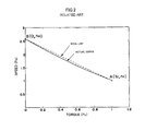
- the T-n characteristic in FIG. 2 represents the performance limit of the motor. Within the range below the T-n characteristic curve in FIG. 2 , the motor starts from a stopped condition and runs up to the maximum angular speed to produce the maximum torque possible without exceeding thermal and electrical limits.
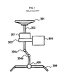
- the motor 308 is controlled by the vector control on the basis of a steering assist current command value Iref determined on the basis of steering torque (or vehicle speed and so on) detected by the torque sensor 307 .
- Iq Iref Id ⁇ 0 (Formula 9)
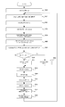
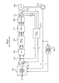
- FIG. 5 shows a control block diagram disclosed in Japanese Patent Application Laid-open No. 08-142886 A.
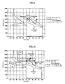
- FIG. 2 is a graph showing a T-n characteristic of a motor.
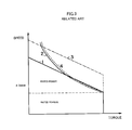
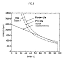
- FIG. 3 is a graph overlaying motor load characteristic curves on motor characteristic lines.
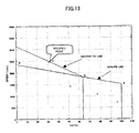
- FIG. 9 is a graph showing a d-axis current command value, a current command value and typical motor rotational speed characteristics (three zones).
- the above Formula 12 means that the point of the maximum output Pmax of the motor differs from the rated operation point of the motor. This difference also depends on the circuit configuration of the motor drive.
- the motor of the electric power steering system yields the maximum output Pmax in a higher rotational speed range than the rated angular speed ⁇ n .
- the present invention is essentially based on the maximum output Pmax, which is the rated output characteristic. This means that, under steady state conditions, the motor must not produce an output exceeding the maximum output Pmax. This requirement can be expressed by Formula 14 below: P ⁇ Pmax (Formula 14)
- the PVC control is a method wherein calculations using the d-axis and q-axis components continue up to the stage of calculating three phase current reference values Iavref, Ibvref and Icvref, and three-phase control is performed at the stage where the motor current is feedbacked for the PI-control.
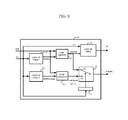
- the current command value calculator calculates a steering assist current command value Iref based on the steering torque T, the vehicle speed and so on.
- the steering assist current command value Iref is inputted to a converter 106 , a q-axis current reference value calculator 103 and a d-axis current reference value calculator 105 in a vector control phase command value calculating section 100 .
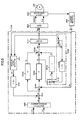
- a resolver 209 detects and sends the angle ⁇ e of a motor 208 as an input to a differentiation circuit 24 that determines an angular speed ⁇ e .
- a two phase-to-three phase converter 104 receives the d-axis current reference value Idref and the q-axis current reference value Iqref to determine the three phase current reference values Iavref, Ibvref and Icvref.
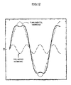
- the back EMF waveform and current waveform of a sinusoidal motor are sinusoidal.
- both the d-axis component (flux control component) and the q-axis component (torque component) will each have a direct current value (constant value).
- the back EMF waveform and current waveform are pseudo-rectangular, and the sinusoidal wave of the first order component is superposed with the sinusoidal waves of the third-, fifth-, seventh-, . . . , nth order waves.
- I ref ⁇ ⁇ l ⁇ ⁇ im [ - ⁇ e ⁇ R ⁇ ⁇ + ⁇ V m ⁇ ⁇ ax 2 ⁇ ( R 2 + ⁇ e 2 ⁇ L 2 ) - ⁇ e 4 ⁇ L 2 ⁇ ⁇ 2 ] ⁇ 1 R 2 + ⁇ e 2 ⁇ L 2 ( Formula ⁇ ⁇ 49 )
- the maximum d-axis current Idmax in the above Formula 55 is “Id ⁇ 0” and therefore an absolute value.
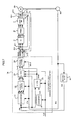
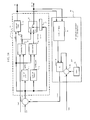
- the hardware implementation of the foregoing calculations is achieved by the configuration shown in FIG. 14 .
- This configuration includes a fit-change-to-battery-voltage section 60 and an adder 18 in addition to the current command value calculator in FIG. 8 .
- the fit-change-to-battery-voltage section 60 includes a setting section 62 outputting a parameter Vdcn, a subtractor 63 subtracting the parameter Vdcn from the battery voltage Vdc, a look-up table 61 receiving the d-axis current command value Id and the limit value Iref_lim of the current command value from the current command value calculator to output a best-fit value, and a multiplier 64 multiplying a voltage ⁇ V from the subtractor 63 with the best-fit value from the look-up table 61 to output the change amount ⁇ e of the angular speed.
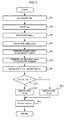
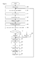
- the look-up table 11 is used to determine the limit value Ireflim of the current command value based on the calculated change amount “ ⁇ e + ⁇ e ” (Step S 22 ), and the look-up table 12 is used to determine the base limit value Iref_base of the current command value (Step S 23 ).
- the limit value Ireflim of the current command value is inputted to the comparator 13
- the base limit value Iref_base of the current command value is inputted to the comparator 14 .
- the order of calculation of the limit value Ireflim of the current command value and the base limit value Iref_base of the current command value is interchangeable.
- the look-up table 61 is used to calculate the best-fit value (Step S 37 ) and input the best-fit value to the multiplier 64 . Based on the best-fit value and the differential voltage ⁇ V, the multiplier 64 determines and inputs the change amount ⁇ e in the angular speed to the adder 18 (Step S 38 ).
Abstract
Description
v=EMF+R·i+L·di/dt (Formula 1)
-
- where “v” is the phase voltage of the motor, “i” the phase current of the motor, “EMF” the phase back EMF voltage, “R” the per-phase resistance, and “L” the per-phase inductance.
Vbat=EMF LL+2R·I (Formula 2)
-
- where “EMFLL” is the back EMF voltage measured between two phases, and “I” is the motor current.
EMF LL =Ke·ω (Formula 3)
-
- where “Ke” is the back EMF constant and “ω” is the angular speed (rotational speed).
T=Kt·I (Formula 4) - where “Kt” is the torque constant.
ω=ω0(1−(I/I 0))=ω0(1−(T/T 0)) [rad/s] (Formula 5) - where “ω0=Vbat/Ke” is the no-load angular speed (one under no-torque condition), “I0=Vbat/2R” the locked rotor current (i.e., stall current) (angular speed=0), and “T0=Kt·I0” the locked rotor torque (i.e., stall torque).
- where “Ke” is the back EMF constant and “ω” is the angular speed (rotational speed).
n=n 0(1−(I/I 0)=n(1−(T/T 0)) [rpm] (Formula 6)
The foregoing Formula 6 expresses a linear torque-speed characteristic (T-n characteristic).
n=n 0−(n 0 −n rated)·T/T rated (Formula 7)
-
- where “n0” is the no-load rotational speed, “nrated” the rated rotational speed, and “Trated” the rated torque.
Iq=Iref
Id=0 (Formula 8)
Iq=Iref
Id≠0 (Formula 9)
Is=√(Iq 2 +Id 2) (Formula 10)
Pn=Tn·ω n (Formula 11)
-
- where “Tn” is the rated torque and “ωn” the rated angular speed.
Pmax>Pn (Formula 12)
Pmax=Tn·(ωn+ωos) (Formula 13)
P<Pmax (Formula 14)
Tlim<Pmax/ωe (Formula 15)
-
- where “ωe” is a mechanical angular speed of the motor.
Tlim<Tn·(ωn+ωos)/ωe (Formula 16)
Ireflim=Tlim/Kt<(Tn·(ωn+ωos)/ωe)/Kt (Formula 17)
Ireflim<In·(ωn+ωos)/ωe (Formula 18)
-
- where “In” is a rated current value of the motor.
Idref=−|Iref|·sin(cos−1(ωb/ωe)) (Formula 19)
Iqref=⅔(Iref×ω m −ed×Idref)/eq (Formula 20)
V an =i a ·Ra+La·di a /dt+e a (Formula 21)
For a balanced motor, each phase of which exhibits identical electrical characteristics to the others, in the case of a single phase, the
v=i·R+L·di/dt+e (Formula 22)
-
- where “R=Ra=Rb=Rc” is the phase resistance of the motor, “L=La=Lb=Lc” the motor phase inductance, and “e” the phase back EMF.
The voltages vd and vq on the d-axis and the q-axis can be given respectively byFormulas 23 and 24:
v d =i d ·R+Ld·di d /dt−ω e ·Ld·i q (Formula 23)
vq=i q ·R+Lq·di q /dt+ω e ·Lq·id+ω e·ψ (Formula 24) - where “Ld” is the d-axis inductance of the motor, “Lq” the q-axis inductance of the motor. In an SPM (Surface PM) motor, “Ld=Lq=L” holds. Meanwhile, “ψ” is the magnetic flux on the d-axis. Generally, “ψ= 4/3·Ke/(2×p)” holds (“Ke” is the back EMF constant and “p” the number of polar pairs).
- where “R=Ra=Rb=Rc” is the phase resistance of the motor, “L=La=Lb=Lc” the motor phase inductance, and “e” the phase back EMF.
vd=id·R−ω e ·Ld·i q (Formula 25)
v q =i q ·R+ω e ·Lq·i d+ωe·ψ (Formula 26)
i q =Iref+Δi q (Formula 27)
-
- where “Iref” is the current command value, and “Δiq” the change amount of the q-axis current iq (Δiq=iq−Iref).
v d =i d ·R−ω e ·Ld·(Iref+Δi q) (Formula 28)
v q=(Iref+Δi q)·R+Lq·di q /dt+ω e ·Lq·i d+ωe·ψ (Formula 29)
Lq·diq/dt=Lq·di q /dθ·dθ/dt=Lq·di q /dθω e =k·ω e (Formula 30)
-
- where “k” is a coefficient for the linear relationship between the q-axis current iq and the differential of the angular speed ωe.
Therefore,Formulas 31 and 32 below hold:
v d =i d ·R−ω e ·Ld·Iref−ω e ·Ld·Δi q (Formula 31)
v q =i ref ·R+ω e ·Lq·i d+ωe ·ψ+k·ω e +Δi q ·R (Formula 32)
- where “k” is a coefficient for the linear relationship between the q-axis current iq and the differential of the angular speed ωe.
i q =Iref+Δi q (Formula 33)
i q =Iref+(i 3 +i 5)sin 6θ+(i 11 +i 13)sin 12θ+ (Formula 34)
√{square root over (v d 2 +v q 2)}≦V max=(V dc/2).k s (Formula 35)
or
v d 2 +v q 2 ≦Vmax2 (Formula 36)
-
- where “Vdc” is the battery voltage measured by the input to the controller, and “ks” the safety coefficient for the modulation technique.
(2) The current constant is given as below:
i d 2 +i q 2 ≦Imax2 (Formula 37) - where “Imax” is the maximum current of the motor or the inverter and is small under steady-state conditions.
Substitution ofFormulas 31 and 32 intoFormula 36yields Formula 38 below:
Vmax2=(i d ·R−ω e ·L·I reflim−ωe ·L·Δi q)2+(I reflim ·R+ω e ·L·I d+ωe ·ψ+k·ω e +Δi q ·R)2 (Formula 38)
- where “Vdc” is the battery voltage measured by the input to the controller, and “ks” the safety coefficient for the modulation technique.
-
- where A1 and B1 are given by
Formulas 40 and 41 below, respectively:
- where A1 and B1 are given by
This is the limit value of the current command value Iref. When the d-axis current command value Id is the value of the maximum current, Formula 43 will be used instead:
I d max=√{square root over (I max 2 −I ref lim 2)} (Formula 43)
Ireflim=f(ωe) (Formula 44)
Any change in the battery voltage Vdc will need to be taken into consideration. Hence:
Ireflim=f(ωe ,V dc) (Formula 45)
Iref=Ireflim and Id=Idmax.
Iref=Iref and Id=Id.
Vmax=Vdc/2×k×1.15 (Formula 46)
(i d ·R−ω e ·L·Iref)2+(Iref·R+ω e ·L·I·i d+ωe·ψ)2 =Vmax2 (Formula 47)
- (1) Case 1: Id=0→Ireflim=f(ω,Vmax)
- This is the base speed range.
- (2) Case 2: Id=Idmax→Ireflim=f(ω,Vmax,Imax)
- In
case 2, the limit current condition is “idmax 2+ireflim 2=Imax 2”.
- In
- (3) Case 3: Ireflim=Ireflim required by specifications→Id=f(ω,Vmax,Ireflim)
(ωe ·L·Iref)2+(Iref·R+ω e·ψ)2 =V max 2 (Formula 48)
i dmax 2 +i reflim 2 =I max 2 (Formula 50)
-
- where coefficients A and B are given by Formulas 52 and 53 below:
Solving the
The above Formula 54 is for the limit value of the current command value Iref in a case where the maximum value of the d-axis current command value Id is used. From
I d max=√{square root over (I max 2 −I ref lim 2)} (Formula 55)
The maximum d-axis current Idmax in the above Formula 55 is “Id<0” and therefore an absolute value.
Formula 56 as a solution is based on the above Formula 47 for the maximum voltage condition. The d-axis current command value Id given by Formula 56 is further limited, using a limit current condition, as in Formula 57 below:
|I d |≦|I d max|=√{square root over (I max 2 −I ref lim 2)} (Formula 57)
Iref=Ireflim, Id=Id.
(2) If Iref≦Ireflim,
Iref=Iref, Id=Id.
V d +ΔV d =i d ·R−(ωe+Δωe)Ld·i q (Formula 58)
v q +Δv q =i q ·R+(ωe+Δωe)Lq·i d+(ωe+Δωe)ψ (Formula 59)
Then, subtraction of the
Δv d=−ωe ·Ld·i q (Formula 60)
Δv q=Δωe ·Lq·i d+Δωe·ψ (Formula 61)
Δv d 2 +Δv q 2 =ΔV 2 (Formula 62)
where
Δv=(Vdc−Vdcn)/2 (Formula 63)
ΔV 2=(Δωe ·L·I q)2+(Δω·L·I d+Δωe·Ψ)2=Δωe 2 ·└L 2·(I d 2 +I q 2)+Ψ2+2·L·I d·Ψ┘ (Formula 64)
Formula 65 means that the change of the change amount Δω is calculated with a look-up table and multiplied by the change amount ΔV.
Claims (12)
Id=−|Iref|·sin(cos−1(ωb/ωe))
Id=−|Iref|·sin(cos−1(ωb/ωe))
Applications Claiming Priority (3)
| Application Number | Priority Date | Filing Date | Title |
|---|---|---|---|
| JP2005076537 | 2005-03-17 | ||
| JP2005-076537 | 2005-03-17 | ||
| PCT/JP2006/305887 WO2006098516A1 (en) | 2005-03-17 | 2006-03-17 | Electric power steering device control method and apparatus |
Publications (2)
| Publication Number | Publication Date |
|---|---|
| US20090234538A1 US20090234538A1 (en) | 2009-09-17 |
| US8285451B2 true US8285451B2 (en) | 2012-10-09 |
Family
ID=36991852
Family Applications (1)
| Application Number | Title | Priority Date | Filing Date |
|---|---|---|---|
| US11/908,887 Active 2029-05-03 US8285451B2 (en) | 2005-03-17 | 2006-03-17 | Method and apparatus for controlling electric power steering system |
Country Status (5)
| Country | Link |
|---|---|
| US (1) | US8285451B2 (en) |
| EP (1) | EP1860766B1 (en) |
| JP (1) | JP5024040B2 (en) |
| KR (1) | KR20070116629A (en) |
| WO (1) | WO2006098516A1 (en) |
Cited By (6)
| Publication number | Priority date | Publication date | Assignee | Title |
|---|---|---|---|---|
| US20110175556A1 (en) * | 2010-01-19 | 2011-07-21 | Kazuaki Tobari | Torque ripple suppression control device for permanent magnet motor and electric power steering system |
| US20120217911A1 (en) * | 2011-02-28 | 2012-08-30 | Deere & Company | Interior permanent magnet machine systems and methods for controlling interior permanent magnet machines |
| US20130211676A1 (en) * | 2010-09-23 | 2013-08-15 | Imre Benyo | Control in an electric steering system |
| US20150054433A1 (en) * | 2008-09-17 | 2015-02-26 | Ford Global Technologies, Llc | System and method for controlling an electric motor |
| US20160368388A1 (en) * | 2015-06-18 | 2016-12-22 | Hyundai Motor Company | Inverter control method for hybrid vehicle |
| US20170088169A1 (en) * | 2015-09-25 | 2017-03-30 | Fuji Jukogyo Kabushiki Kaisha | Steering assistance control apparatus |
Families Citing this family (43)
| Publication number | Priority date | Publication date | Assignee | Title |
|---|---|---|---|---|
| US7630807B2 (en) * | 2004-07-15 | 2009-12-08 | Hitachi, Ltd. | Vehicle control system |
| JP4527596B2 (en) * | 2005-05-12 | 2010-08-18 | シャープ株式会社 | MOTOR CONTROL DEVICE AND ELECTRIC DEVICE USING THE SAME |
| JP5034375B2 (en) * | 2006-08-25 | 2012-09-26 | 日本精工株式会社 | Electric power steering device |
| US8164289B2 (en) * | 2006-10-16 | 2012-04-24 | Mitsuba Corporation | Brushless motor and control method of brushless motor |
| FR2911698B1 (en) * | 2007-01-24 | 2009-07-10 | Airbus France Sas | DEVICE FOR CONTROLLING ELECTROMECHANICAL ACTUATOR. |
| JP4618614B2 (en) * | 2007-04-10 | 2011-01-26 | 三菱電機株式会社 | Electric power steering control device |
| JP5200460B2 (en) * | 2007-09-06 | 2013-06-05 | 日本精工株式会社 | Motor drive control device |
| JP4609515B2 (en) * | 2008-04-02 | 2011-01-12 | トヨタ自動車株式会社 | Vehicle steering control device |
| US9807849B2 (en) * | 2008-09-10 | 2017-10-31 | Enlighted, Inc. | Automatically commissioning lighting controls using sensing parameters of the lighting controls |
| JP5262931B2 (en) * | 2009-04-01 | 2013-08-14 | トヨタ自動車株式会社 | Electric power steering device |
| JP5327333B2 (en) * | 2009-10-30 | 2013-10-30 | トヨタ自動車株式会社 | Vehicle travel control device |
| JP5333422B2 (en) * | 2010-12-07 | 2013-11-06 | 株式会社デンソー | Power converter |
| US8410737B2 (en) * | 2011-02-28 | 2013-04-02 | Deere & Company | Device and method for generating an initial controller lookup table for an IPM machine |
| JP5897298B2 (en) * | 2011-10-12 | 2016-03-30 | 株式会社ミツバ | Brushless motor control method, brushless motor control device, brushless motor, and electric power steering device |
| US8896244B2 (en) * | 2011-12-15 | 2014-11-25 | Steering Solutions Ip Holding Corporation | Motor control system for limiting regenerative current |
| RU2491705C1 (en) * | 2012-01-10 | 2013-08-27 | Федеральное государственное бюджетное образовательное учреждение высшего профессионального образования "Владимирский государственный университет имени Александра Григорьевича и Николая Григорьевича Столетовых" (ВлГУ) | Electric drive |
| US8924082B2 (en) | 2012-03-30 | 2014-12-30 | Steering Solutions Ip Holding Corporation | System and method for controlling a motor |
| US9663139B2 (en) | 2013-02-26 | 2017-05-30 | Steering Solutions Ip Holding Corporation | Electric motor feedforward control utilizing dynamic motor model |
| GB201304156D0 (en) * | 2013-03-07 | 2013-04-24 | Trw Ltd | Motor Control |
| US9136785B2 (en) | 2013-03-12 | 2015-09-15 | Steering Solutions Ip Holding Corporation | Motor control system to compensate for torque ripple |
| US9143081B2 (en) | 2013-03-14 | 2015-09-22 | Steering Solutions Ip Holding Corporation | Motor control system having bandwidth compensation |
| JP6194466B2 (en) * | 2013-04-11 | 2017-09-13 | パナソニックIpマネジメント株式会社 | Motor drive device |
| US9199665B2 (en) * | 2013-05-15 | 2015-12-01 | Jtekt Corporation | Electric power steering system |
| DE102013217451A1 (en) * | 2013-09-02 | 2015-03-05 | Robert Bosch Gmbh | Method for data transmission in a battery management system |
| US10389289B2 (en) | 2014-02-06 | 2019-08-20 | Steering Solutions Ip Holding Corporation | Generating motor control reference signal with control voltage budget |
| US10003285B2 (en) | 2014-06-23 | 2018-06-19 | Steering Solutions Ip Holding Corporation | Decoupling current control utilizing direct plant modification in electric power steering system |
| WO2016007705A1 (en) * | 2014-07-10 | 2016-01-14 | Trw Automotive U.S.Llc | System and method for robust active disturbance rejection in electric power steering |
| KR102300785B1 (en) * | 2014-10-07 | 2021-09-13 | 현대모비스 주식회사 | Control apparatus and method for mdps drive motor |
| US9809247B2 (en) | 2015-01-30 | 2017-11-07 | Steering Solutions Ip Holding Corporation | Motor control current sensor loss of assist mitigation for electric power steering |
| JP7064880B2 (en) | 2015-04-01 | 2022-05-11 | イェール ユニバーシティー | Iron platinum particles for attachment of biologics on medical implants |
| JP6355835B2 (en) * | 2015-05-01 | 2018-07-11 | 三菱電機株式会社 | Electric power steering control device and electric power steering control method |
| JP6445937B2 (en) * | 2015-07-03 | 2018-12-26 | 日立オートモティブシステムズ株式会社 | Electric power steering device |
| US10618544B2 (en) | 2016-05-20 | 2020-04-14 | Steering Solutions Ip Holding Corporation | Radially preloaded rack bearing |
| US11290042B2 (en) * | 2016-05-25 | 2022-03-29 | Steering Solutions Ip Holding Corporation | Supply current limiting of DC machines |
| US10530282B2 (en) * | 2016-05-25 | 2020-01-07 | Steering Solutions Ip Holding Corporation | Current capability limiting of DC machines |
| US10135368B2 (en) | 2016-10-01 | 2018-11-20 | Steering Solutions Ip Holding Corporation | Torque ripple cancellation algorithm involving supply voltage limit constraint |
| JP6237938B1 (en) * | 2016-10-18 | 2017-11-29 | 株式会社安川電機 | Multi-axis motor control system, motor control device, and motor control method |
| DE102017210747A1 (en) | 2017-06-27 | 2018-12-27 | Bayerische Motoren Werke Aktiengesellschaft | A method for preheating a battery of an electrically operated motor vehicle and charging device |
| US11198466B2 (en) | 2017-11-03 | 2021-12-14 | Steering Solutions Ip Holding Corporation | Wedge adjuster plug |
| CN108749645B (en) * | 2018-04-21 | 2020-11-03 | 浙江合众新能源汽车有限公司 | Control protection method for electric vehicle during neutral sliding |
| US11177762B2 (en) * | 2019-02-20 | 2021-11-16 | Volvo Car Corporation | Electric motor control for preventing torque ripple |
| JP2021079893A (en) * | 2019-11-22 | 2021-05-27 | 株式会社ジェイテクト | Steering control device |
| US11926221B2 (en) * | 2020-09-24 | 2024-03-12 | GM Global Technology Operations LLC | Open-loop control for transient operation of a rotary electric machine |
Citations (26)
| Publication number | Priority date | Publication date | Assignee | Title |
|---|---|---|---|---|
| JPS60197183A (en) | 1984-03-19 | 1985-10-05 | Mitsubishi Electric Corp | Speed controller of induction motor |
| US5299648A (en) | 1991-07-22 | 1994-04-05 | Jidosha Kiki Co., Ltd. | Driver current limiting method in electric power steering apparatus |
| US5361210A (en) * | 1991-09-28 | 1994-11-01 | Koyo Seiko Co., Ltd. | Current control for electric power steering apparatus motor |
| EP0638457A2 (en) | 1993-08-10 | 1995-02-15 | Toyota Jidosha Kabushiki Kaisha | Method and apparatus for driving and controlling synchronous motor using permanent magnets as its field system |
| JPH07170800A (en) | 1993-09-17 | 1995-07-04 | Matsushita Electric Ind Co Ltd | Control method for motor |
| JPH089699A (en) | 1994-06-15 | 1996-01-12 | Matsushita Electric Ind Co Ltd | Control method of motor |
| JPH08108858A (en) | 1994-10-06 | 1996-04-30 | Nippon Seiko Kk | Control device of motor-driven power steering device |
| JPH08142886A (en) | 1994-11-24 | 1996-06-04 | Nippon Seiko Kk | Control device for motor-driven power steering |
| US5602735A (en) * | 1993-10-26 | 1997-02-11 | Mitsubishi Denki Kabushiki Kaisha | Control apparatus for motor-driven power steering system in which power suppy to an electric clutch is reduced upon detection of a malfunction |
| US5656911A (en) | 1994-12-27 | 1997-08-12 | Fuji Electric Company | Circuit for driving permanent-magnet synchronous motor using proportional controller |
| US5758741A (en) * | 1994-10-31 | 1998-06-02 | Jidosha Kiki Co., Ltd. | Vehicle power steering system |
| US6013994A (en) * | 1996-10-01 | 2000-01-11 | Nsk Ltd. | Controller of electric power-steering system |
| JP2001018822A (en) | 1999-07-08 | 2001-01-23 | Toyota Motor Corp | Electric power steering apparatus for vehicle |
| US6184637B1 (en) * | 1998-10-26 | 2001-02-06 | Honda Giken Kogyo Kabushiki Kaisha | Electric power steering apparatus |
| US20020125064A1 (en) * | 2001-03-12 | 2002-09-12 | Koyo Seiko Co., Ltd. | Electric power steering apparatus |
| US20020166716A1 (en) * | 2001-05-08 | 2002-11-14 | Honda Giken Kogyo Kabushiki Kaisha | Electric power steering apparatus |
| FR2825853A1 (en) | 2001-06-12 | 2002-12-13 | Siemens Automotive Sa | Method of control of synchronous electric motor, uses control of quadrature and direct axis current components to produce linear torque output till current threshold is released, then limits current |
| JP2003079181A (en) | 2001-09-04 | 2003-03-14 | Mitsubishi Electric Corp | Electric power steering control equipment and control method |
| DE10216104A1 (en) | 2002-04-12 | 2003-11-06 | Zf Lenksysteme Gmbh | Operating steering system for motor vehicle involves generating phase current as braking current and limiting to maximum value if defined threshold revolution rate exceeded by drive motor |
| JP2004040883A (en) | 2002-07-02 | 2004-02-05 | Honda Motor Co Ltd | Electric power steering arrangement |
| JP2004201487A (en) | 2002-11-28 | 2004-07-15 | Nsk Ltd | Motor and its drive controlling apparatus |
| US20040217729A1 (en) | 2003-04-30 | 2004-11-04 | Visteon Global Technologies, Inc. | Electric power assist steering system and method of operation |
| JP2005007991A (en) | 2003-06-18 | 2005-01-13 | Unisia Jkc Steering System Co Ltd | Electric power steering device |
| US20060001392A1 (en) * | 2004-06-30 | 2006-01-05 | Toshiyuki Ajima | Motor drive apparatus, electric actuator and electric power steering apparatus |
| EP1662650A1 (en) | 2004-11-25 | 2006-05-31 | Kawasaki Jukogyo Kabushiki Kaisha | Synchronous motor control method and synchronous motor control system |
| US20070158132A1 (en) * | 2004-01-13 | 2007-07-12 | Nsk Ltd. & Nsk Steering Systems Co., Ltd. | Control device for electric power steering apparatus |
-
2006
- 2006-03-17 US US11/908,887 patent/US8285451B2/en active Active
- 2006-03-17 KR KR1020077023059A patent/KR20070116629A/en not_active Application Discontinuation
- 2006-03-17 JP JP2007508261A patent/JP5024040B2/en not_active Expired - Fee Related
- 2006-03-17 EP EP06729835.6A patent/EP1860766B1/en not_active Expired - Fee Related
- 2006-03-17 WO PCT/JP2006/305887 patent/WO2006098516A1/en active Application Filing
Patent Citations (26)
| Publication number | Priority date | Publication date | Assignee | Title |
|---|---|---|---|---|
| JPS60197183A (en) | 1984-03-19 | 1985-10-05 | Mitsubishi Electric Corp | Speed controller of induction motor |
| US5299648A (en) | 1991-07-22 | 1994-04-05 | Jidosha Kiki Co., Ltd. | Driver current limiting method in electric power steering apparatus |
| US5361210A (en) * | 1991-09-28 | 1994-11-01 | Koyo Seiko Co., Ltd. | Current control for electric power steering apparatus motor |
| EP0638457A2 (en) | 1993-08-10 | 1995-02-15 | Toyota Jidosha Kabushiki Kaisha | Method and apparatus for driving and controlling synchronous motor using permanent magnets as its field system |
| JPH07170800A (en) | 1993-09-17 | 1995-07-04 | Matsushita Electric Ind Co Ltd | Control method for motor |
| US5602735A (en) * | 1993-10-26 | 1997-02-11 | Mitsubishi Denki Kabushiki Kaisha | Control apparatus for motor-driven power steering system in which power suppy to an electric clutch is reduced upon detection of a malfunction |
| JPH089699A (en) | 1994-06-15 | 1996-01-12 | Matsushita Electric Ind Co Ltd | Control method of motor |
| JPH08108858A (en) | 1994-10-06 | 1996-04-30 | Nippon Seiko Kk | Control device of motor-driven power steering device |
| US5758741A (en) * | 1994-10-31 | 1998-06-02 | Jidosha Kiki Co., Ltd. | Vehicle power steering system |
| JPH08142886A (en) | 1994-11-24 | 1996-06-04 | Nippon Seiko Kk | Control device for motor-driven power steering |
| US5656911A (en) | 1994-12-27 | 1997-08-12 | Fuji Electric Company | Circuit for driving permanent-magnet synchronous motor using proportional controller |
| US6013994A (en) * | 1996-10-01 | 2000-01-11 | Nsk Ltd. | Controller of electric power-steering system |
| US6184637B1 (en) * | 1998-10-26 | 2001-02-06 | Honda Giken Kogyo Kabushiki Kaisha | Electric power steering apparatus |
| JP2001018822A (en) | 1999-07-08 | 2001-01-23 | Toyota Motor Corp | Electric power steering apparatus for vehicle |
| US20020125064A1 (en) * | 2001-03-12 | 2002-09-12 | Koyo Seiko Co., Ltd. | Electric power steering apparatus |
| US20020166716A1 (en) * | 2001-05-08 | 2002-11-14 | Honda Giken Kogyo Kabushiki Kaisha | Electric power steering apparatus |
| FR2825853A1 (en) | 2001-06-12 | 2002-12-13 | Siemens Automotive Sa | Method of control of synchronous electric motor, uses control of quadrature and direct axis current components to produce linear torque output till current threshold is released, then limits current |
| JP2003079181A (en) | 2001-09-04 | 2003-03-14 | Mitsubishi Electric Corp | Electric power steering control equipment and control method |
| DE10216104A1 (en) | 2002-04-12 | 2003-11-06 | Zf Lenksysteme Gmbh | Operating steering system for motor vehicle involves generating phase current as braking current and limiting to maximum value if defined threshold revolution rate exceeded by drive motor |
| JP2004040883A (en) | 2002-07-02 | 2004-02-05 | Honda Motor Co Ltd | Electric power steering arrangement |
| JP2004201487A (en) | 2002-11-28 | 2004-07-15 | Nsk Ltd | Motor and its drive controlling apparatus |
| US20040217729A1 (en) | 2003-04-30 | 2004-11-04 | Visteon Global Technologies, Inc. | Electric power assist steering system and method of operation |
| JP2005007991A (en) | 2003-06-18 | 2005-01-13 | Unisia Jkc Steering System Co Ltd | Electric power steering device |
| US20070158132A1 (en) * | 2004-01-13 | 2007-07-12 | Nsk Ltd. & Nsk Steering Systems Co., Ltd. | Control device for electric power steering apparatus |
| US20060001392A1 (en) * | 2004-06-30 | 2006-01-05 | Toshiyuki Ajima | Motor drive apparatus, electric actuator and electric power steering apparatus |
| EP1662650A1 (en) | 2004-11-25 | 2006-05-31 | Kawasaki Jukogyo Kabushiki Kaisha | Synchronous motor control method and synchronous motor control system |
Non-Patent Citations (2)
| Title |
|---|
| Communication and Supplementary European Search Report dated May 12, 2011 in counterpart European Patent Application No. 06 72 9835. |
| Japanese Office Action dated Nov. 11, 2011, issued in counterpart Japanese Patent Application No. 2007-508261. |
Cited By (12)
| Publication number | Priority date | Publication date | Assignee | Title |
|---|---|---|---|---|
| US20150054433A1 (en) * | 2008-09-17 | 2015-02-26 | Ford Global Technologies, Llc | System and method for controlling an electric motor |
| US9917537B2 (en) * | 2008-09-17 | 2018-03-13 | Ford Global Technologies, Llc | System and method for controlling an electric motor |
| US20110175556A1 (en) * | 2010-01-19 | 2011-07-21 | Kazuaki Tobari | Torque ripple suppression control device for permanent magnet motor and electric power steering system |
| US8410735B2 (en) * | 2010-01-19 | 2013-04-02 | Kokusan Denki Co., Ltd. | Torque ripple suppression control device for permanent magnet motor and electric power steering system |
| US20130211676A1 (en) * | 2010-09-23 | 2013-08-15 | Imre Benyo | Control in an electric steering system |
| US9031747B2 (en) * | 2010-09-23 | 2015-05-12 | Thyssenkrupp Presta Ag | Control in an electric steering system |
| US20120217911A1 (en) * | 2011-02-28 | 2012-08-30 | Deere & Company | Interior permanent magnet machine systems and methods for controlling interior permanent magnet machines |
| US8552673B2 (en) * | 2011-02-28 | 2013-10-08 | Deere & Company | Interior permanent magnet machine systems and methods for controlling interior permanent magnet machines |
| US20160368388A1 (en) * | 2015-06-18 | 2016-12-22 | Hyundai Motor Company | Inverter control method for hybrid vehicle |
| US9796276B2 (en) * | 2015-06-18 | 2017-10-24 | Hyundai Motor Company | Inverter control method for hybrid vehicle |
| US20170088169A1 (en) * | 2015-09-25 | 2017-03-30 | Fuji Jukogyo Kabushiki Kaisha | Steering assistance control apparatus |
| US10023227B2 (en) * | 2015-09-25 | 2018-07-17 | Subaru Corporation | Steering assistance control apparatus |
Also Published As
| Publication number | Publication date |
|---|---|
| US20090234538A1 (en) | 2009-09-17 |
| EP1860766A1 (en) | 2007-11-28 |
| JP5024040B2 (en) | 2012-09-12 |
| EP1860766B1 (en) | 2015-10-28 |
| EP1860766A4 (en) | 2011-06-15 |
| KR20070116629A (en) | 2007-12-10 |
| JPWO2006098516A1 (en) | 2008-08-28 |
| WO2006098516A1 (en) | 2006-09-21 |
Similar Documents
| Publication | Publication Date | Title |
|---|---|---|
| US8285451B2 (en) | Method and apparatus for controlling electric power steering system | |
| US9136785B2 (en) | Motor control system to compensate for torque ripple | |
| US7969106B2 (en) | Vector controller for permanent-magnet synchronous electric motor | |
| US8686672B2 (en) | Motor control device and electric power steering device | |
| JP3559258B2 (en) | Steering control device | |
| EP1276225B1 (en) | Motor control apparatus for reducing higher harmonic current | |
| JP3396440B2 (en) | Control device for synchronous motor | |
| US9143081B2 (en) | Motor control system having bandwidth compensation | |
| US7474067B2 (en) | Electric power steering system | |
| WO2009123113A1 (en) | Motor control device and electric power steering device | |
| EP1672780A2 (en) | Lead-angle control method and device for operating permanent magnet synchronous motor in flux weakening regions | |
| JP2007159368A (en) | Control unit of motor drive system | |
| US8823300B2 (en) | Electric motor control device | |
| US20020171387A1 (en) | Apparatus and method for controlling permanent magnet electric machines | |
| JP4797565B2 (en) | Motor drive control device | |
| JP4650110B2 (en) | Electric motor control device | |
| JPH11299297A (en) | Controller for permanent magnet synchronous motor | |
| JP5397664B2 (en) | Motor control device | |
| EP2066018A2 (en) | Motor control device | |
| JP4299628B2 (en) | Control device for electric power steering device | |
| JP2008068666A (en) | Electric power steering device | |
| JP3323900B2 (en) | Control device for linear motor electric vehicle | |
| JP2012235556A (en) | Motor controller | |
| US20240063746A1 (en) | Controller for rotary machine | |
| JP2009081915A (en) | Motor controller |
Legal Events
| Date | Code | Title | Description |
|---|---|---|---|
| AS | Assignment |
Owner name: NSK LTD., JAPAN Free format text: ASSIGNMENT OF ASSIGNORS INTEREST;ASSIGNORS:TA, CAOMINH;JIANG, CHUNHAO;KOBAYASHI, HIDEYUKI;REEL/FRAME:019835/0899 Effective date: 20070910 |
|
| STCF | Information on status: patent grant |
Free format text: PATENTED CASE |
|
| FEPP | Fee payment procedure |
Free format text: PAYOR NUMBER ASSIGNED (ORIGINAL EVENT CODE: ASPN); ENTITY STATUS OF PATENT OWNER: LARGE ENTITY |
|
| FPAY | Fee payment |
Year of fee payment: 4 |
|
| MAFP | Maintenance fee payment |
Free format text: PAYMENT OF MAINTENANCE FEE, 8TH YEAR, LARGE ENTITY (ORIGINAL EVENT CODE: M1552); ENTITY STATUS OF PATENT OWNER: LARGE ENTITY Year of fee payment: 8 |