US8252081B2 - Water dissipation device and method - Google Patents
Water dissipation device and method Download PDFInfo
- Publication number
- US8252081B2 US8252081B2 US12/539,088 US53908809A US8252081B2 US 8252081 B2 US8252081 B2 US 8252081B2 US 53908809 A US53908809 A US 53908809A US 8252081 B2 US8252081 B2 US 8252081B2
- Authority
- US
- United States
- Prior art keywords
- water
- dissipation device
- outer cover
- cover structure
- flow
- Prior art date
- Legal status (The legal status is an assumption and is not a legal conclusion. Google has not performed a legal analysis and makes no representation as to the accuracy of the status listed.)
- Expired - Fee Related, expires
Links
- XLYOFNOQVPJJNP-UHFFFAOYSA-N water Substances O XLYOFNOQVPJJNP-UHFFFAOYSA-N 0.000 title claims abstract description 367
- 238000000034 method Methods 0.000 title description 2
- 230000029058 respiratory gaseous exchange Effects 0.000 claims abstract description 94
- 239000000463 material Substances 0.000 claims abstract description 48
- 239000012466 permeate Substances 0.000 claims abstract description 16
- 239000012530 fluid Substances 0.000 claims description 23
- 229920000728 polyester Polymers 0.000 claims description 12
- 239000004677 Nylon Substances 0.000 claims description 11
- 239000000853 adhesive Substances 0.000 claims description 11
- 230000001070 adhesive effect Effects 0.000 claims description 11
- 229920001778 nylon Polymers 0.000 claims description 11
- 230000037361 pathway Effects 0.000 claims description 11
- 230000000007 visual effect Effects 0.000 claims description 9
- 239000002131 composite material Substances 0.000 claims description 7
- 238000006073 displacement reaction Methods 0.000 claims description 6
- 238000004891 communication Methods 0.000 claims description 5
- 229920001169 thermoplastic Polymers 0.000 claims description 5
- 239000004416 thermosoftening plastic Substances 0.000 claims description 5
- 238000004026 adhesive bonding Methods 0.000 claims description 3
- 239000002648 laminated material Substances 0.000 claims description 3
- 239000007789 gas Substances 0.000 description 41
- 239000007788 liquid Substances 0.000 description 17
- 230000009471 action Effects 0.000 description 9
- 230000005494 condensation Effects 0.000 description 8
- 238000009833 condensation Methods 0.000 description 8
- 230000008878 coupling Effects 0.000 description 8
- 238000010168 coupling process Methods 0.000 description 8
- 238000005859 coupling reaction Methods 0.000 description 8
- 239000004744 fabric Substances 0.000 description 7
- 230000000241 respiratory effect Effects 0.000 description 7
- 238000012546 transfer Methods 0.000 description 7
- 230000005484 gravity Effects 0.000 description 6
- 239000012528 membrane Substances 0.000 description 6
- -1 polypropylene Polymers 0.000 description 6
- 241000894006 Bacteria Species 0.000 description 5
- 241000700605 Viruses Species 0.000 description 5
- 238000001816 cooling Methods 0.000 description 5
- 239000004743 Polypropylene Substances 0.000 description 4
- 230000008901 benefit Effects 0.000 description 4
- 229920001155 polypropylene Polymers 0.000 description 4
- 238000010521 absorption reaction Methods 0.000 description 3
- 238000010276 construction Methods 0.000 description 3
- 238000001179 sorption measurement Methods 0.000 description 3
- JOYRKODLDBILNP-UHFFFAOYSA-N Ethyl urethane Chemical compound CCOC(N)=O JOYRKODLDBILNP-UHFFFAOYSA-N 0.000 description 2
- 229920001410 Microfiber Polymers 0.000 description 2
- 239000004698 Polyethylene Substances 0.000 description 2
- XSTXAVWGXDQKEL-UHFFFAOYSA-N Trichloroethylene Chemical group ClC=C(Cl)Cl XSTXAVWGXDQKEL-UHFFFAOYSA-N 0.000 description 2
- 230000005540 biological transmission Effects 0.000 description 2
- 239000004020 conductor Substances 0.000 description 2
- 238000005516 engineering process Methods 0.000 description 2
- 238000003475 lamination Methods 0.000 description 2
- 239000003658 microfiber Substances 0.000 description 2
- 210000003632 microfilament Anatomy 0.000 description 2
- 239000000203 mixture Substances 0.000 description 2
- 238000012986 modification Methods 0.000 description 2
- 230000004048 modification Effects 0.000 description 2
- 238000012544 monitoring process Methods 0.000 description 2
- 239000000123 paper Substances 0.000 description 2
- 239000012071 phase Substances 0.000 description 2
- 229920000573 polyethylene Polymers 0.000 description 2
- 229920000642 polymer Polymers 0.000 description 2
- 238000011176 pooling Methods 0.000 description 2
- 239000002904 solvent Substances 0.000 description 2
- UBOXGVDOUJQMTN-UHFFFAOYSA-N trichloroethylene Natural products ClCC(Cl)Cl UBOXGVDOUJQMTN-UHFFFAOYSA-N 0.000 description 2
- 238000009825 accumulation Methods 0.000 description 1
- 230000000295 complement effect Effects 0.000 description 1
- 230000003247 decreasing effect Effects 0.000 description 1
- 238000009826 distribution Methods 0.000 description 1
- 230000000694 effects Effects 0.000 description 1
- 150000002148 esters Chemical class 0.000 description 1
- 238000010438 heat treatment Methods 0.000 description 1
- 208000015181 infectious disease Diseases 0.000 description 1
- 238000004519 manufacturing process Methods 0.000 description 1
- 230000013011 mating Effects 0.000 description 1
- 229940075473 medical gases Drugs 0.000 description 1
- 238000000465 moulding Methods 0.000 description 1
- 238000005192 partition Methods 0.000 description 1
Images


Classifications
-
- A—HUMAN NECESSITIES
- A61—MEDICAL OR VETERINARY SCIENCE; HYGIENE
- A61M—DEVICES FOR INTRODUCING MEDIA INTO, OR ONTO, THE BODY; DEVICES FOR TRANSDUCING BODY MEDIA OR FOR TAKING MEDIA FROM THE BODY; DEVICES FOR PRODUCING OR ENDING SLEEP OR STUPOR
- A61M16/00—Devices for influencing the respiratory system of patients by gas treatment, e.g. mouth-to-mouth respiration; Tracheal tubes
- A61M16/08—Bellows; Connecting tubes ; Water traps; Patient circuits
- A61M16/0808—Condensation traps
-
- A—HUMAN NECESSITIES
- A61—MEDICAL OR VETERINARY SCIENCE; HYGIENE
- A61M—DEVICES FOR INTRODUCING MEDIA INTO, OR ONTO, THE BODY; DEVICES FOR TRANSDUCING BODY MEDIA OR FOR TAKING MEDIA FROM THE BODY; DEVICES FOR PRODUCING OR ENDING SLEEP OR STUPOR
- A61M16/00—Devices for influencing the respiratory system of patients by gas treatment, e.g. mouth-to-mouth respiration; Tracheal tubes
- A61M16/0003—Accessories therefor, e.g. sensors, vibrators, negative pressure
- A61M2016/0027—Accessories therefor, e.g. sensors, vibrators, negative pressure pressure meter
Definitions
- the present invention relates generally to a medical device. More particularly, the present invention is related to a water dissipation device for placement with a breathing circuit.
- a breathing circuit delivers medical gas to a patient under pressure in a prescribed volume and breathing rate.
- the medical gas is often humidified by a humidifier located at or near the ventilator or respirator.
- the optimum respiratory circuit delivers 100% RH medical gases @ 35 to 39 degrees C. to the patient while reducing the amount of humidity and subsequent condensate delivered back to the ventilator through the expiratory limb. Therefore, the humidified gas has to travel through all or most of the tubing and has time to cool. Cooling of the gas leads to rainout or condensation in the breathing tube and collection of water within the breathing circuit.
- a heating wire provided along the length of the tube.
- the wire may be provided within the interior of the tubing or alternatively may be embedded along the interior of the tubing.
- the wire heats the humidified gas traveling through the tubing to prevent the gas from cooling, thus preventing the problem of water condensing out of the gas traveling through the breathing circuit.
- the manufacture of such heated wire respiratory circuits can be time consuming and costly.
- a water collection apparatus is typically placed in the expiratory limb of the respiratory circuit in front of the ventilator or respirator to collect and manually remove excessive condensation prior to the gases entering the ventilator or respirator. It is known that excessive condensate entering a ventilator or respirator from the expiratory limb of a respiratory circuit can harm the device.
- the water collection device is designed to trap the condensed water vapor in a removable container. When the container is removed, a valve can be actuated to create a gas tight seal for the breathing circuit.
- this type of water collection device has to be monitored and manually emptied, causing risk of patient or caregiver infection.
- the improved apparatus for removing or decreasing water vapor, moisture, or condensate in a breathing circuit reduce or eliminate the need to heat the exhalation limb of the breathing tube and the need to use currently known water collection or other dissipation devices.
- an apparatus in different embodiments provides an improved water dissipation device for placement with a breathing circuit where said water dissipation device will eliminate the need to use a secondary water collection device or manually remove the water condensate and will instead allow for removal of water vapor and/or moisture from the circuit from inside the device out to the surroundings through action of osmosis or permeation or dissipation of such water vapor and/or moisture automatically while the device is coupled to an active breathing circuit.
- the device includes in one embodiment a composite structure having walls made of different layers including a water or moisture wicking material and water vapor breathable medium, which structure at least partially bounds an inner flow space defined by the device providing an extended area and dwell time for moisture in humidified gases to travel through the composite structure and thereby be removed from the flow in a breathing circuit to which the device is coupled.
- a water dissipation device for removing water vapor or moisture from a breathing circuit.
- the device includes an upper lid portion, an entry port for receiving flow from the breathing circuit, and an exit port for flow exiting the device.
- An outer cover structure extends from the upper lid portion to define an enclosed volume and a depth between the upper lid portion and a bottom end portion of the device.
- An inner frame extends from the upper lid portion inside the outer cover structure.
- the device defines an inner flow space inside the enclosed volume at least for fluid flow from the entry point through the device to the exit port.
- the outer cover structure includes at least a first layer of water or moisture wicking material and a second layer of water vapor breathable medium over the first layer.
- the outer cover structure has an inner surface area bounding at least a portion of the inner flow space such that water vapor or moisture can permeate from the inner flow space through the outer cover structure out of device.
- the device can further include an inner cup structure extending from the upper lid portion into the enclosed volume.
- the inner cup structure can be enclosed by the inner frame and define and bound at least a portion of the inner flow space.
- a water dissipation device for removing water vapor or moisture from a breathing circuit.
- the device includes an upper lid portion, an entry port for receiving flow from the breathing circuit, and an exit port for flow exiting the device.
- An outer cover structure extends from the upper lid portion to define an enclosed volume and having a depth between the upper lid portion and a bottom end portion of the device.
- An inner frame extends from the upper lid portion inside the outer cover structure. The device defines an inner flow space inside the enclosed volume at least for fluid flow from the entry point through the device to the exit port.
- the inner frame includes a substantially cylindrical annular wall portion extending from the upper lid portion for at least one half of the depth of the device or outer cover structure.
- the outer cover structure includes at least a first layer of water or moisture wicking material and a second layer of water vapor breathable medium over the first layer.
- the outer cover structure has an inner surface area bounding at least a portion of the inner flow space such that water vapor or moisture can permeate from the inner flow space through the outer cover structure out of device.
- the outer cover structure narrowly surrounds the annular wall portion of the inner frame to define a narrow annular flow space therebetween, the annular flow space being a portion of the inner flow space and in fluid communication with the entry port.
- FIG. 1 is a schematic view illustrating a breathing circuit
- FIG. 2 is an exploded view illustrating a water dissipation device according to an embodiment of the invention
- FIG. 3 is a cross sectional view illustrating the embodiment of the water dissipation device illustrated in FIG. 2 ;
- FIG. 4 is a top view of the embodiment of the water dissipation device illustrated in FIGS. 2 and 3 ;
- FIG. 5 is a three-quarter view illustrating the water dissipation device according to another embodiment of the present invention.
- FIG. 6 is a top view of the embodiment illustrated in FIG. 5 ;
- FIG. 7 is an exploded view of the embodiment illustrated in FIGS. 5 and 6 ;
- FIG. 8 is a cross sectional view of the embodiment illustrated in FIGS. 5-7 ;
- FIG. 9 is a three-quarter view illustrating another embodiment of the present invention.
- FIG. 10 is a bottom view of the embodiment illustrated in FIG. 9 ;
- FIG. 11 is an exploded view of the embodiment illustrated in FIGS. 9 and 10 ;
- FIG. 12 is a side view illustrating another embodiment of the present invention.
- FIG. 13 is an exploded view of the embodiment illustrated in FIG. 12 .
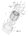
- FIG. 14 is an exploded view illustrating another embodiment of the present invention.
- FIG. 15 is a cross-sectional view of the embodiment illustrated in FIG. 14 .
- FIG. 16 is a three-quarter view illustrating another embodiment of the present invention.
- FIG. 17 is an exploded view of the embodiment illustrated in FIG. 16 .
- FIG. 18 is a cross-sectional view of the embodiment illustrated in FIGS. 16 and 17 .
- FIG. 19 is an exploded view of a water dissipation device in accordance with another embodiment of the invention.
- FIG. 20 is a cross-sectional view of the assembled water dissipation device shown in FIG. 19 , showing some of the flow paths for fluid flowing through the device.
- FIG. 20A is a transverse sectional view of the assembled water dissipation device shown in FIG. 19 , taken along section A-A in FIG. 20 .
- FIG. 20B is a transverse sectional view of the assembled water dissipation device shown in FIG. 19 , taken along section B-B in FIG. 20 .
- FIG. 20C is a schematic magnified view of a portion the assembled water dissipation device shown in FIG. 19 , taken from area C in FIG. 20 .
- FIG. 21 is an exterior view of the assembled water dissipation device in FIG. 19 .
- FIG. 22 is an illustration of a water dissipation device according to one or more embodiments of the invention.
- FIG. 23 is an exploded view illustrating a water dissipation device according to an embodiment of the invention.
- FIG. 24 is a view illustrating the water dissipation device of FIG. 23 , in assembled form but without an outer cover structure.
- FIG. 25 is a top view of the water dissipation device of FIG. 23 .
- FIG. 25A is a cross-sectional view of the water dissipation device of FIG. 23 taken along section A-A in FIG. 25 .
- FIG. 26 is an exploded view illustrating a water dissipation device according to another embodiment of the invention.
- FIG. 27 is a view illustrating the water dissipation device of FIG. 26 , in assembled form but without an outer cover structure.
- FIG. 28 is a view illustrating an inner frame structure of the water dissipation device of FIG. 26 .
- FIG. 29 is a top view of the water dissipation device of FIG. 26 .
- FIG. 30 is a cross-sectional view of the water dissipation device of FIG. 26 in assembled form taken along section X-X in FIG. 29 .
- FIG. 31A is a cross-sectional view of a portion of the water dissipation device taken along section A-A in FIG. 30 .
- FIG. 31B is a detailed view of a portion of the water dissipation device shown in FIG. 30 in region “B” therein.
- FIG. 31C is a detailed view of a portion of the water dissipation device shown in FIG. 30 in region “C” therein.
- FIGS. 32A-32C illustrate examples of connector ports or couplings for connecting or coupling the water dissipation device of various embodiments of the invention with a breathing circuit.
- An embodiment in accordance with the present invention provides a water dissipation device to rapidly remove water vapor or condensate from a humidified medical gas traveling through a breathing circuit between a ventilator and a patient or the patient and the ventilator.
- the present invention includes a water dissipation device having a housing defining entry and exit ports for coupling to the breathing circuit and a breathable medium permeable to water vapor and impermeable to liquid water, viruses and bacteria enclosed within said housing.
- FIG. 1 is a schematic view illustrating a breathing circuit 10 including a water dissipation device 12 .
- the water dissipation device 12 is placed in the breathing circuit 10 between a ventilator 14 and a breathing tube 17 from a patient.
- the breathing circuit 10 is completed by a second breathing tube 16 extending between the patient and the ventilator.
- the breathing circuit 10 is a closed system wherein liquid water and/or gases are not able to enter or leave the breathing circuit, except for the release of water vapor. Therefore, the breathing circuit 10 is a closed system except with regard to the passage of water vapor.
- FIG. 2 is an exploded view illustrating the water dissipation device 12 according to a preferred embodiment of the invention.
- the water dissipation device 12 includes a housing 18 having a cylindrical bottom container 20 .
- the cylindrical bottom container 20 has a side wall 22 that defines a top opening 24 and a bottom surface 26 .
- a lid 28 mounted over the top opening 24 .
- the housing 18 defines an entry port 30 and an exit port 32 , and more specifically the lid 28 defines the entry port 30 and the exit port 32 .
- the entry port 30 and the exit port 32 allow the water dissipation device 12 to be connected to a breathing circuit, such that the entry port 30 is connected to an expiratory limb of a breathing tube from the patient and the exit port 32 is connected to the rest of the same breathing tube directed toward a ventilator.
- water vapor vents 34 are defined by the housing 18 , and more specifically are defined along a periphery of the lid 28 .
- a plurality of the water vapor vents 34 are disposed around an outer edge of a top surface of the lid 28 .
- the lid 28 can also be manufactured from a thermally conductive material to facilitate the cooling of the respiratory gases and increase water condensation,
- An annular or tubular breathable medium 36 is enclosed in the housing 18 .
- the tubular breathable medium 36 may be pleated to increase the surface area of the breathable medium within the housing 18 .
- the breathable medium 36 may also line at least a portion of an inside surface 38 of the side wall 22 .
- a “breathable medium” is formed of a material that is permeable to water vapor and impermeable to liquid water and gases other than water vapor.
- the breathable medium 36 allows water vapor to exit the water dissipation device while eliminating the need to open the water dissipation device to empty a reservoir of water and, therefore, allows the system to remain closed.
- FIG. 3 is a cross sectional view that further illustrates the embodiment of the water dissipation device illustrated in FIG. 2 .
- the housing 18 defines a first flow path 40 of humidified gas between the entry port 30 and the exit port 32 .
- the humidified gas travels into the water dissipation device 12 via the entry port 30 , through the housing 18 and exits the water dissipation device 12 via the exit port 32 .
- the first flow path 40 therefore generally corresponds to the main flow path through the water dissipation device along the breathing circuit.
- the housing also defines a second flow path 42 for water vapor that extends from the entry port 30 through the tubular breathable medium 36 to at least one opening defined by the housing, other than the exit port 32 .
- this at least one opening includes the water vapor vents 34 defined by the lid of the housing 18 .
- water vapor in the humidified gas may permeate through breathable medium 36 and exit through the water vapor vents 34 .
- liquid water and other gases cannot permeate the breathable medium 36 and exit through the water vapor vents 34 .
- the bottom surface 26 of the outer housing 18 defines an orifice 44 to connect the water dissipation device 12 to an input air source.
- the housing 18 therefore, defines a third flow path 46 from the orifice 44 through the water dissipation device 12 and out through the water vapor vents 34 .
- the third flow path 46 provides a route for air introduced by the auxiliary compressed dry air input source to blow condensation off of the breathable medium to reduce liquid water collecting in the water dissipation device, and increase the efficiency of the breathable permeable medium.
- the annular or tubular breathable medium 36 defines a central channel 37 within which the second flow path 42 may follow.
- FIG. 4 is a top view of the lid 28 of the embodiment of the water dissipation device illustrated in FIGS. 2 and 3 .
- FIG. 4 illustrates the entry port 30 and exit port 32 and the water vapor vents 34 in more detail.
- the entry port 30 and the exit port 32 are disposed on a top surface of the lid 28 and the lid 28 defines a tubular connector portion 48 that couples the water dissipation device 12 to a breathing tube 16 .
- multiple water vapor vents 34 are disposed around the outer edge of the lid 28 .
- the number and placement of the water vapor vents 34 are not limited by this embodiment and there may be any number of water vapor vents 34 disposed in any position on the lid 28 or on the remainder of the housing 18 .
- FIG. 5 is a three-quarter view illustrating a water dissipation device 112 according to another embodiment of the present invention.
- the housing 118 includes a cylindrical bottom container 120 that has side wall 122 defining a top opening 124 .
- the housing also includes a lid 128 that is mounted on the top opening 124 .
- the housing 118 defines an entry port 130 and an exit port 132 .
- FIG. 6 is a top view of the embodiment illustrated in FIG. 5 .
- FIG. 6 illustrates in more detail the lid 128 and the entry port 130 and the exit port 132 .
- the lid 128 is the portion of the housing that defines the entry port 30 and the exit port 132 .
- the entry port 130 and the exit port 132 are disposed on the top surface 150 of the lid 128 and include a tubular connector portion 148 that couples the water dissipation device 112 to a breathing tube.
- FIG. 7 is an exploded view of the embodiment illustrated in FIGS. 5 and 6 .
- FIG. 7 illustrates in more detail the structure of the housing 118 and the tubular breathable medium 136 . Threads on the lid 128 as well as corresponding threads on the cylindrical bottom container 120 couple the lid 128 to the cylindrical bottom container 120 , such that there is an air tight seal between them.
- the lid 128 has a tubular cage 152 that extends into the cylindrical bottom container 20 of the housing 18 .
- the tubular cage 152 has fins 154 that extend along the span of the housing 118 .
- the fins 154 are separated by longitudinal openings or spaces that define water vapor vents 156 between the fins 154 .
- An annular or tubular breathable medium 136 is also disposed within the cylindrical bottom container 120 , and it is positioned between the tubular cage 152 and the sidewalls 122 of the cylindrical bottom container 120 of the outer housing 118 .
- FIG. 8 is a cross sectional view of the embodiment illustrated in FIGS. 5 through 7 .
- FIG. 8 illustrates the housing 118 and the breathable medium 136 in a fully assembled condition.
- the lid 128 and the cylindrical bottom container 120 couple together to form an air tight seal.
- the tubular cage 152 extends from a bottom surface of the lid 128 to the bottom surface 126 of the cylindrical bottom container 120 .
- the tubular breathable medium 136 is disposed around and supported by the tubular cage 152 .
- a first flow path 140 is defined by the housing 118 and extends through the water dissipation device 112 directly from the entry port 130 and through to the exit port 132 as shown in FIGS. 7 and 8 .
- the humidified gas generally flowing through the breathing circuit to which the device of the present invention is attached can therefore travel through the water dissipation device 112 via the first flow path 140 .
- a second flow path 142 is also defined by the housing 118 and extends from the entry port 130 through the tubular breathable medium 136 and out of the water dissipation device 112 via the water vapor vents 156 defined by the fins 154 of the tubular cage 152 .
- Water vapor in the humidified gas may permeate the breathable medium 136 to exit through the water vapor vents 156 , but liquid water, bacteria, viruses and other gases cannot permeate the breathable medium 136 .
- the second flow path provides for water vapor permeation from the outer surface to the inner surface of the tubular breathable medium 136 .
- Breathable medium 136 defines a central channel 137 through which the final portion of the second flow patent 142 flows.
- FIGS. 9 , 10 and 11 illustrate another embodiment of the water dissipation device of the present invention.
- the housing 218 defines the entry port 130 and exit port 132 for coupling a water dissipation device 212 to a breathing circuit.
- the housing 218 has a cylindrical bottom container 120 having a side wall 122 that defines a top opening 124 .
- the lid 128 is mounted on the top opening 124 and preferably defines the entry port 130 and the exit port 132 .
- the housing 218 also defines an opening 160 in a bottom surface 161 of the housing 218 .
- a flat disk breathable medium 262 is disposed in said housing 218 and covers the opening 160 in the bottom surface of the housing 218 .
- a first flow path 140 between the entry port 130 and the exit port 132 is defined by the housing 218 .
- the housing 218 also defines a second flow path 242 from the entry port 130 through the housing 218 and out through the opening 160 and flat disk breathable medium 262 on the bottom surface 161 of the cylindrical bottom container 120 . Only water vapor passes through the flat disk breathable medium 262 because it is permeable to water vapor but impermeable to liquid water, bacteria, viruses and other gases.
- FIG. 12 illustrates a side view of another embodiment of the water dissipation device of the present invention.
- FIG. 13 illustrates an exploded view of the embodiment illustrated in FIG. 12 .
- a water dissipation device 312 has a cylindrical caged body 364 that encloses an annular or tubular breathable medium 336 .
- the cylindrical caged body 364 is formed of two halves 368 and 372 , which can be separable.
- the water dissipation device 312 has a first end cap 366 defining the entry port 330 .
- a second end portion 370 defines the exit port 332 .
- the circular end caps 366 and 370 are held in place inside complementary grooves on the inside of portions of the caged body halves 368 and 372 .
- a plurality of windows 374 are defined by the cylindrical caged body 364 to allow for egress of water vapor from the water dissipation device 312 .
- the cylindrical caged body 364 encloses a tubular breathable medium 336 which lines at least a portion of an inside surface 376 of the cylindrical caged body 364 .
- the tubular breathable medium 336 is pleated and permeable to water vapor but impermeable to liquid water, bacteria, viruses and other gases.
- the breathable medium 36 should not be limited by this description and may take various forms or positions within the cylindrical caged body 364 .
- the cylindrical caged body 364 defines a first flow path 340 between the entry port 330 and the exit port 332 . Additionally, the cylindrical caged body 364 defines a second flow path 342 from the entry port 330 , through the breathable medium 336 and out of the water dissipation device 312 via the windows 374 in the cylindrical caged body 364 . Only water vapor passes through the tubular breathable medium 36 in the second flow path 342 .
- FIG. 14 is an exploded view illustrating the water dissipation device 412 according to a preferred embodiment of the invention.
- the water dissipation device 412 includes a housing 418 having a caged cylindrical bottom container 420 .
- the caged cylindrical bottom container 420 has a side wall 422 that defines a top opening 424 and a bottom surface 426 .
- Also included in the housing 418 is a lid 428 mounted over the top opening 424 .
- the housing 418 defines an entry port 430 and an exit port 432 , and more specifically the lid 428 defines the entry port 430 and the exit port 432 .
- the entry port 430 and the exit port 432 allow the water dissipation device 412 to be connected to a breathing circuit, such that the entry port 430 is connected to an expiratory limb of a breathing tube from the patient and the exit port 432 is connected to another tube directed toward a ventilator.
- water vapor vents 434 are defined by the housing 418 , and more specifically are defined along a periphery of the lid 428 .
- the cylindrical bottom container 420 and the lid 428 also define windows 435 which allow for egress of water vapor from the water dissipation device 412 .
- the lid 428 can also be manufactured from a thermally conductive material to facilitate the cooling of the respiratory gases and increase water condensation.
- a tubular breathable medium 436 is enclosed in the caged housing 418 .
- the tubular breathable medium 436 may be pleated to increase the surface area of the breathable medium within the housing 418 and may also be perforated.
- the breathable medium 436 may also line at least a portion of an inside surface 438 of the side wall 422 .
- the breathable medium 436 is formed of a material that is permeable to water vapor and impermeable to liquid water and other gases.
- the breathable medium 436 allows water vapor to exit the water dissipation device while eliminating the need to open the water dissipation device to empty a reservoir of water and, therefore, allows the system to remain closed.
- FIG. 15 is a cross sectional view that further illustrates the embodiment of the water dissipation device illustrated in FIG. 14 .
- the caged housing 418 defines a first flow path 440 of humidified gas between the entry port 430 and the exit port 432 .
- the humidified gas travels into the water dissipation device 412 via the entry port 430 , through the housing 418 and exits the water dissipation device 412 via the exit port 432 .
- the first flow path 440 therefore generally corresponds to the main flow path through the water dissipation device along the breathing circuit, except that in this embodiment, a partition or baffle element 433 extends in the housing 418 perpendicular to the axis through the entry and exit ports 430 and 432 , which causes to further define the first flow path 440 to extend farther into the housing 418 and nearer to the channel 437 formed inside the annular breathable medium 436 .
- the housing also defines a second vapor or flow path 442 that extends from the entry port 430 through the tubular breathable medium 436 , and then out to either the water vapor vents 434 defined by the housing 418 , or out of the housing 418 through the windows 435 .
- a second vapor or flow path 442 that extends from the entry port 430 through the tubular breathable medium 436 , and then out to either the water vapor vents 434 defined by the housing 418 , or out of the housing 418 through the windows 435 .
- liquid water and other gases cannot permeate the breathable medium 436 and exit through the windows 435 .
- the bottom surface 426 of the outer housing 418 defines an orifice 444 to connect the water dissipation device 412 to an input air source.
- the housing 418 therefore, defines a third flow path 446 from the orifice 444 through the water dissipation device 412 and out through the water vapor vents 434 , or out through the windows 435 .
- the third flow path 446 provides a route for air introduced by the auxiliary compressed dry air input source to blow condensation off of the breathable medium to reduce liquid water collecting in the water dissipation device, and increase the efficiency of the breathable permeable medium.
- FIG. 16 is a three-quarter view illustrating a water dissipation device 512 according to another embodiment of the present invention.
- the housing 518 includes a caged cylindrical bottom container 520 that has side wall 522 defining a top opening 524 .
- the housing also includes the lid 528 that is mounted on the top opening 524 .
- the housing 518 defines an entry port 130 and an exit port 532 .
- the side wall 522 of the caged cylindrical bottom container 520 defines a plurality of windows 535 .
- An annular or tubular breathable medium is encased inside the cage structure of the housing 518 against the sidewalls 522 .
- a first flow path 540 flows from the entry port 540 through to the exit port 532 , while a second water vapor flow path 542 flows from the entry port 540 down into the housing 518 though a central channel defined by the annular breathable medium 536 , and then out through the breathable medium 536 and the windows 535 .
- FIG. 17 is an exploded view of the embodiment illustrated in FIG. 16 .
- FIG. 17 illustrates in more detail the structure of the housing 518 and the tubular breathable medium 536 . Threads on the lid 528 as well as corresponding threads on the cylindrical bottom container 520 couple the lid 528 to the cylindrical bottom container 520 .
- the lid 528 has a tubular cage 552 that extends into the cylindrical bottom container 520 of housing 518 .
- the tubular cage 552 has fins 554 that extend along the span of the housing 518 .
- the fins 554 are separated by longitudinal openings or spaces that define water vapor vents 556 between the fins 554 .
- the tubular cage 552 has a flat disk 553 to form a bottom for the tubular cage 552 .
- a tubular breathable medium 536 is also disposed within the cylindrical bottom container 520 , and it is positioned between the tubular cage 552 and the cylindrical bottom container 520 of the outer housing 518 .
- FIG. 18 is a cross sectional view of the embodiment illustrated in FIGS. 16 and 17 .
- FIG. 18 illustrates the housing 518 and the breathable medium 536 in a fully assembled condition.
- the lid 528 and the cylindrical bottom container 520 couple together.
- the tubular cage 552 extends from a bottom surface of the lid 528 to the bottom surface 526 of the cylindrical bottom container 520 .
- the tubular breathable medium 536 is disposed around and supported by the tubular cage 552 .
- a first flow path 540 is defined by the housing 518 and extends through the entry port 530 , through the water dissipation device and through the exit port 532 .
- the humidified gas generally flowing through the breathing circuit to which the device of the present invention is attached can therefore travel through the water dissipation device 512 via the first flow path 540 .
- a second water vapor flow path 542 is also defined by housing 518 and extends from entry port 530 through tubular breathable medium 536 and out of the water dissipation device 512 via the water vapor vents 556 defined by the fins 554 of the tubular cage 552 and out through the windows 535 defined by the caged cylindrical bottom container 520 .
- Water vapor in the humidified gas may permeate the breathable medium 536 to exit through the water vapor vents 556 , but liquid water, bacteria, viruses and other gases cannot permeate the breathable medium 536 .
- An alternative embodiment of the device shown in FIGS. 17 and 18 could also omit the bottom caged cylindrical housing body 520 such that the second flow path 542 flowed directly through breathable medium 536 out to the surroundings.
- FIG. 19 is an exploded view of a water dissipation device in accordance with another embodiment of the invention.
- the inventive device is shown relative to a gravity vector “g” as shown, such that “upper” and “lower” portions of the device are construed relative to said vector, “upper” being in the opposite direction from vector g, and “lower” being in the direction of vector g.
- the invention includes a water dissipation device 600 having an upper lid structure 602 defining an entry port 604 and an exit port 606 for coupling the device to a breathing circuit.
- the water dissipation device 600 is preferably placed at the end of the expiratory limb of a breathing circuit before the ventilator, although the positioning can be anywhere along a breathing circuit.
- a cover or cover structure 610 is attached or coupled to the upper lid 602 via any means, but can include, in the embodiment shown in FIG. 19 , a pair of semi-circular securing ring clamps or arc structures 612 which matingly fit around the perimeter of upper lid 602 .
- the cover structure 610 is a cover element which can be described as a hollow, bag-shaped or bucket-shaped element defining a top opening 614 and closed bottom 616 .
- the walls of cover structure 610 can have any width or thickness, but are relatively thin and can be flexible, such as a membrane. Alternatively, the cover structure 610 can be rigid and relatively inflexible.
- the material of cover structure 610 has a first inner layer made of water or moisture wicking material, and a second outer layer surrounding the first inner layer, the second outer layer made of a water vapor breathable medium.
- the cover structure 610 is therefore a moisture accumulation and water vapor transfer means, providing a pathway for water vapor to exit a breathing circuit via flow into the water dissipation device 600 and through the cover structure 610 .
- the structural arrangement of the parts of the water dissipation device 610 are such that the device defines an inner flow space or series of flow spaces fluidly coupled to the entry port 604 and exit port 606 . Furthermore, because of the water vapor breathable medium in the cover element 610 , water vapor can also flow from inside of the device out to the environment surrounding the device, providing a flow path for water vapor to exit a breathing circuit to which the water dissipation device 610 is coupled. This provides a way to reduce the water vapor and moisture content which can build up in a breathing circuit when it is connected to a patient.
- FIG. 20 is a cross-sectional view of the assembled water dissipation device 600 , showing some of the flow paths for fluid flowing through the device.
- an inner frame element 620 is enclosed by the cover structure 610 .
- the shape of the cover structure 610 is such that it narrowly surrounds the inner frame 620 to define an inner flow space 625 which is at least partially disposed between the inner frame and cover structure.
- the inner frame 620 is large enough relative to the cover structure 610 that it encloses a majority of a volume enclosed by the cover structure. This provides a set of narrow and annular flow spaces in the inner flow space 625 between the walls of the inner frame 620 and cover structure 610 .
- the arrangement of the inner frame 620 inside of the cover structure 610 also reduces the overall volume or the inner flow space 625 and consequently the compliance of the device 600 when connected to a breathing circuit.
- the flow paths provided by the inner flow space 625 are at least partially bounded by the inner layer of water or moisture wicking material in the cover element 610 .
- humidified gases flow through the inner flow space 625 along arrows T as shown in FIG. 20 .
- the inner flow space 625 is tortuous and includes a number of different spaces and volumes all fluidly coupled together which wind around the inner frame 620 .
- An upper cap 630 is also included which is positioned within the volume created when the upper lid 602 and cover element 610 are attached together.
- the upper cap 630 is shaped to have a lower end with a perimeter 632 which mates to the upper opening or perimeter 622 of the inner frame 620 .
- the upper cap 630 is covered over its upper surface 634 by the upper lid 602 defining a volume or space 640 therebetween.
- Flow T from a breathing circuit coupled to the entry port 604 thereby flows through to the space 640 between the upper lid 602 and upper cap 630 and then impinges against upper surface 634 of the upper cap 630 and is radially distributed out from the central axis A to a plurality of holes 635 defined by a rim 636 on the perimeter of the upper cap 630 .
- the upper cap 630 can therefore be characterized as an inner flow dispersal lid element disposed between the inner frame 620 and upper lid 602 and adjacent an upper end of the annular volume 650 , the inner flow dispersal lid element 630 defining the plurality of openings 635 for dispersing flow received through the entry port 604 into the annular volume 650 of the inner flow space 625 of the device 600 .
- the cover structure 610 can have a substantially cylindrical portion 615 between its open top end 614 and closed bottom end 616 and the inner frame 620 can have a substantially cylindrical portion 621 enclosed by the substantially cylindrical portion 615 of the cover structure.
- substantially cylindrical it is understood that deviations from a cylindrical shape are possible, such that elliptical, oval, rectangular, square, or other cross-sectional shapes are possible for the cover structure 610 and inner frame 620 .
- the cover structure 610 and inner frame 620 are substantially cylindrical such that each element encloses a relatively large volume in relation to its outer surface area, in accordance with the geometric properties of a cylinder.
- FIG. 21 is an exterior view of the assembled water dissipation device 600 in FIG. 19 .
- the inner frame 620 also defines a lower opening 660 proximate the lower end 616 of the cover 610 . As best shown in FIG. 20 , the lower opening 660 is in fluid communication with the annular volume 650 and the exit port 606 defined by the upper lid 602 via a tube 670 which is surrounded by the inner frame 620 .
- the inner frame 620 can further include a plurality of longitudinal ribs 680 along an outside surface of its cylindrical portion 621 which can, in one embodiment, support the cover element 610 .
- the annular volume 650 can be separated into one or more longitudinal channels 685 defined between the inner frame 620 and cover element 610 , each channel being longitudinally bounded by two longitudinal ribs 680 . This is best shown in FIGS. 20A and 20B , which are transverse sectional views of the assembled water dissipation device shown in FIG. 19 , taken along sections A-A and B-B, respectively, in FIG. 20 .
- FIG. 20C is a schematic magnified view of a portion of the walls of cover structure 610 , taken from area C indicated in FIG. 20 , which shows inner layer 690 of water or moisture wicking material and outer layer 692 of water vapor breathable medium which make up cover structure 610 .
- Both inner layer 690 and outer layer 692 are water vapor breathable in that both allow passage of water vapor.
- inner layer 690 is made of wicking material which allows for adsorption and/or absorption of both moisture and water in any phase, gas or liquid, using a capillary action, while the water vapor breathable medium of outer layer 692 permits the passage of water vapor only and not liquid water.
- wicking material in inner layer 690 are a knit or non-woven cloth or fabric, made of polyester, polyester and polypropylene blends, nylon, polyethylene or paper, and can be microfilaments or microfiber material such as Evolon® brand fabric material made by Freudenberg & Co. KG.
- a particular example of wicking material would be a non-woven material of 70% polypropylene and 30% polyester.
- outer layer 692 of water vapor breathable medium are Sympatex®M brand water vapor permeable membranes made of polymers made by Sympatex Technologies.
- the wicking material can be laminated to the water vapor breathable medium to form a composite material.
- the arrangement of flow spaces which are bounded by the cover structure 610 provides a relatively large surface area of the inner layer of water wicking material in the cover structure 610 which bounds a substantial part of the inner flow space 625 .
- the surface area of the cover structure 610 can vary in a range from 120 to 160 square inches, but can also be at least 80 to 100 square inches. While the size of the cover structure 610 and overall device 600 is limited by the need for a reduced compliance when connected to a breathing circuit, it understood that the particular size of the present invention can be made to suit the needs of the patient.
- the arrangement of flow spaces in the present invention also provides a relatively long dwell time for fluid flow through the device 600 from the entry port 604 through to the exit port 606 , since the fluid flowing from the entry port 604 is directed furthest away from the entry port 604 to the lower end portion of the device 600 at the lower end 616 of the cover 610 , and then back through tube 670 to the exit port 606 to maximize the travel time of fluid flow through the device.
- the capillary action of the inner layer of water wicking material causes moisture or water vapor to be adsorbed on the inner surface of cover structure 610 and absorbed into the inner layer, which water vapor or moisture then enters the second outer layer of the cover structure 610 which is made of a water vapor breathable material which allows water vapor to flow from within the device 600 out to the surroundings.
- the present invention therefore provides a superior way of removal of moisture or water vapor from a breathing circuit, which is better than water traps or other fluid dissipation or moisture removal devices known in the prior art.
- the superior performance of the present invention is due to a number of factors, including one or more of: (i) the greater surface area of flow spaces 625 bounded by a water vapor breathable medium afforded by the arrangement of the structure of the device 600 ; (ii) the use of a water wicking material in the inner layer of the cover element 610 ; and/or (iii) the relatively long dwell times and flow paths through the device 600 from the entry port 604 to the exit port 606 .
- the result of the inventive apparatus disclosed is that when device 600 is connected to a breathing circuit, rainout or condensation in the breathing tube and collection of water within the breathing circuit is significantly reduced.
- FIG. 22 is an illustration of a water dissipation device according to one or more additional embodiments of the invention, as more fully explained below.
- the device 700 can include two ports 704 and 706 extending from an upper lid portion 702 .
- the ports 704 and 706 can be coupled to a breathing circuit and can be entry or exit ports for flow to enter and exit from the breathing circuit.
- An outer cover structure 710 extends from the upper lid structure and is generally bucket or cup shaped, as explained more fully herein. In the device shown in FIG. 22 , the device is fully assembled and can be representative of the basic features of the embodiments discussed further herein.
- the device 700 shows that the outer cover structure 710 extends for a depth 711 from the upper lid portion 702 , and has a bucket or cup-shaped configuration 705 that encloses a volume inside.
- the device 700 therefore provides in inner flow space between the entry and exit ports bounded and enclosed by combination of the outer cover structure 710 , upper lid portion 702 and its bucket of cup-shaped configuration extending into the volume enclosed by the outer cover structure.
- breathing gases containing water vapor or moisture can circulate and allow for such water vapor and moisture to collect inside in liquid form, similar to a water trap.
- the present invention provides an outer cover structure 710 which is made of at least two layers, including an first, inner layer made of water or moisture wicking material, and second, outer layer made of a water vapor breathable material.
- the first layer of wicking material adsorbs and/or absorbs water or moisture inside the device 700 which have circulated or condensed inside its inner flow space and in contact with the inner surface area of the outer cover structure 710 .
- the capillary action provided by the wicking material draws water or moisture from one region of the outer cover structure 710 to another region of the outer cover structure 710 and thus enables a greater surface area of the outer cover structure 710 to collect, absorb, and transfer water vapor or condensate.
- the water vapor or moisture can then diffuse or transfer by osmosis through the second layer of the outer cover structure 710 which is made of a material that transfers only water vapor, as is well known in the art, and explained in more detail herein.
- the device 700 provides an inner flow space and contact surface area bounded and enclosed by the outer cover structure 710 made of at least the two layers discussed herein, which enables water vapor or moisture to dissipate from the breathing circuit flow to which the device is connected out to the surroundings. This effectively and automatically removes water vapor and condensate from a breathing circuit which is novel and inventive over all known devices in this field.
- FIG. 23 is an exploded view illustrating a water dissipation device according to an exemplary embodiment of the invention.
- the device 800 shown in FIG. 23 can be a smaller version of the inventive device suited more particularly for application with pediatric patients, and is similar in assembled form in certain respects to the features of the device 700 shown in FIG. 22 .
- the device 800 has three main components which have been exploded in the view of FIG. 23 along a depth axis 801 extending along the center of the device from an upper end to a lower end of the device 800 .
- the device 800 is preferably oriented such that its depth axis 801 is aligned with the direction of gravity, shown by gravity vector “g” in FIG. 23 , although deviations from this orientation or different alignments are possible.
- the components of the device 800 include a lid and inner cup assembly 802 , an outer cover structure 810 , and an inner frame 820 .
- inner frame 820 fits inside outer cover structure 810 through a mouth or upper top opening 814 defined by the outer cover structure 810
- lid and inner cup assembly 802 fits on top of an upper mouth or top opening 822 of the inner frame 820 , with an inner cup structure portion 805 fitting through said opening 822 to be enclosed by the inner frame 820 when the device is fully assembled.
- the inner frame 820 can be a truss-like structure having a bucket-shaped or cup-shaped configuration and can be made up of a series of interconnected span or strut elements 827 which also define a plurality of windows, spaces or openings 823 between the various span or strut elements 827 .
- the lid and inner cup assembly includes at least an upper lid portion 803 , an entry port 804 and an exit port 806 as best shown in FIG. 23 .
- the inner cup structure 805 extends from the upper lid portion 803 as a bucket or cup-shaped structure into a volume circumscribed or enclosed by the inner frame and outer cover structure when the device 800 is in fully assembled form, described in more detail below.
- FIG. 24 is a view illustrating the water dissipation device 800 of FIG. 23 , in assembled form but without the outer cover structure 810 , showing how the lid and inner cup assembly 802 and in particular the inner cup structure 805 fits inside the inner frame 820 .
- the lid and inner cup assembly 802 thus has an upper lid portion 803 which is a kind of lid or cap having an outer rim 803 a which has a circumferential perimeter which envelops or fits around the upper circumferential edge or perimeter 820 a of the inner frame 820 as shown in FIGS. 23 and/or 24 .
- the center area 803 b enclosed by the inner cup structure 805 of the upper lid portion 803 is hollowed out defining a space or volume which extends downwards along axis 801 as an inner volume enclosed by the inner cup structure 805 having sidewalls 805 a which extend downwards from the outer rim 803 a .
- Outer rim 803 a further defines a lip or overhang which fits over the circumferential perimeter 820 a of inner frame 820 .
- FIG. 25 is a top view of the water dissipation device of FIG. 23 .
- FIG. 25 is a top view of the water dissipation device of FIG. 23 , showing the contours and features of parts of the inner cup structure 805 in outline.
- FIG. 25A is a cross-sectional view of the water dissipation device of FIG. 23 taken along section A-A in FIG. 25 . As shown in FIG.
- the cross-sectional shape of the inner cup structure 805 transverse to the depth axis of the device is not circular and instead includes at least two curved sidewalls 805 d and 805 e which partially define a channel or flow pathway directly below the entry and exit ports 804 and 806 respectively, which flow pathways extend through said ports through the upper lid portion 803 and into an inner flow space inside the device 800 bounded by the upper lid portion 803 , inner cup structure 805 , and outer cover structure 810 , when the device 800 is fully assembled as shown in FIG. 25A .
- the inner flow space is further bounded by the structure of the inner frame 820 in that any flow inside the flow space must flow around the spans and struts of the frame 820 .
- the device 800 defines a cross-sectional shape transverse to the depth that can be elliptical and non-circular.
- FIG. 23 there is shown two axes E 1 and E 2 , which span the width of the device 800 and its components along a plane transverse to and normal with depth axis 801 , shown as transverse plane “E” in FIG. 25A .
- axis E 1 and axis E 2 can be aligned with the major and minor axes, respectively, of the ellipse approximated by said cross-sectional shape.
- the width of the device 800 and its outer cover structure 810 can be approximated as a first width “W 1 ” along axis E 1 , and as a second width “W 2 ” along axis E 2 , which widths can be the widths of the elliptical span of the transverse cross-section of the top opening 814 of the outer cover structure 810 along the major and minor axes of said elliptical span. Furthermore, as shown in FIG.
- the depth of the device 800 and its outer cover structure 810 can be approximated as a depth “D 1 ” extending from transverse plane “E” along depth axis 801 , which transverse plane is coincident with the upper end and upper top opening 814 of the outer cover structure 810 as well as the approximate level where outer rim 820 a of inner frame 820 mates with the lip or outer rim 803 a of the upper lid portion 803 .
- the embodiment of the invention shown in FIGS. 23-25A includes a water dissipation device for removing water vapor or moisture from a breathing circuit.
- the device 800 includes an upper lid portion 803 , an entry port 804 for receiving flow from a breathing circuit, and an exit port 806 for flow exiting the device 800 .
- the outer cover structure 810 extends from the upper lid portion 803 to define an enclosed volume V 1 bounded by the surface area of the outer cover structure 810 and the elliptical span of the transverse cross-section of top opening 814 , as shown in FIG. 23 and having a depth D 1 as shown in FIG. 25A between the upper lid portion and a lower or bottom end portion 816 of the device 800 .
- V 1 enclosed volume
- the lower or bottom end portion 816 of the device also is the lower or bottom end of the outer cover structure 810 , since such outer cover structure is a bucket or cup-shaped structure which encloses and covers the lower or bottom end of the enclosed volume V 1 and inner frame 820 which fits inside said volume V 1 .
- Enclosed volume V 1 therefore is a space or volume bounded by an inner surface of the outer cover structure 820 and the upper transverse plane “E” proximate the upper lid portion 803 .
- the inner frame 820 extends from the upper lid portion 803 inside the outer cover structure 810 into enclosed volume V 1 , such that the device 800 defines a complex inner flow space inside the enclosed volume V 1 at least for fluid flow from the entry point 804 through the inside of the device 800 and eventually to the exit port 806 .
- the entry and exit ports could be reversed such that the entry port is 806 and the exit port is 804 , since flow inside the inner flow space in enclosed volume V 1 could easily flow either way between said ports, depending on which way the device 800 is coupled to a breathing circuit.
- the inner flow space defined inside device 800 is shown in FIG. 25A as a number of spaces 825 which are bounded by the configuration of the outer cover structure 810 , inner cup structure 805 and in particular its sidewalls 805 a , and the upper lid portion 803 and the span of entry and exit ports 804 and 806 along transverse plane E.
- the inner flow space 825 is further bounded by the structure of the inner frame 820 in that the inner frame 820 displaces some of the volume inside the enclosed volume inside the outer cover structure 810 and so any flow inside the flow space 825 must flow around the spans and struts of the frame 820 .
- FIG. 25A The inner flow space defined inside device 800 is shown in FIG. 25A as a number of spaces 825 which are bounded by the configuration of the outer cover structure 810 , inner cup structure 805 and in particular its sidewalls 805 a , and the upper lid portion 803 and the span of entry and exit ports 804 and 806 along transverse plane E.
- the flow of breathing gases or fluid from a breathing circuit coupled to entry port 804 is shown as directional pathways F 1 , which flow first enters the device 800 through the entry port 804 and then passes transverse top plane “E” and enters the enclosed volume inside the outer cover structure 810 and into the inner flow space 825 therein.
- inner cup structure 805 extends from the upper lid portion 803 into the enclosed volume, the flow along F 1 inside a portion of the inner flow space is bounded by the sidewalls 805 a of the inner cup structure 805 which displaces a significant portion of the enclosed volume, such that the flow is urged and directed to flow first towards the lower or bottom end 816 of the device 800 , into the portion 825 a of the inner flow space 825 proximate to bottom end 816 , before returning though another portion of the inner flow space 825 up past again the sidewalls 805 a of the inner cup 805 and to through to the exit port 806 .
- the device 800 directs the flow F 1 to tend to flow from the upper end of the device 800 near top plane “E” down to the lower end 816 first before exiting the device, such that the travel and dwell time of flow inside the device is lengthened or maximized.
- This causes the flow F 1 inside flow space 825 to have greater contact with the inner surface area of outer cover structure 810 .
- This lengthening of the travel and dwell time, and increase of contact with the inner surface area of the outer cover structure 810 enhances the water dissipation function of the device, as explained more fully below.
- the outer cover structure 810 of water dissipation device 800 includes at least a first layer of water or moisture wicking material and a second layer of water vapor breathable medium over the first layer.
- the first layer of water or moisture wicking material is what forms the inner surface area of the outer cover structure 810 which bounds at least a portion of the inner flow space 825 such that water vapor or moisture can permeate from the inner flow space 825 through the outer cover structure 810 and out of device 800 , as shown by a few exemplary directional flow indicators “F 2 ” as shown in FIG. 25A .
- the dissipation of water vapor or moisture can take place across the entire surface span of outer cover structure 810 which bounds the inner flow space 825 and is exposed on its outer surface to the atmosphere or surroundings. If the concentration of water vapor or moisture inside the inner flow space 825 and/or the breathing gases or fluids flowing therein is higher than the concentration of water vapor or moisture outside the device 800 , then water vapor or moisture will tend to travel through capillary action, osmosis, and/or other modes into first the first layer of water and/or moisture wicking material, and then through the second layer of water vapor breathable material, such that water vapor effectively exits the device 800 along a pathway other than through the exit port 806 .
- the present invention therefore allows for water vapor or moisture to be effectively and automatically removed from high humidity or water vapor or moisture containing breathing gases flowing from breathing circuits to which the device 800 is connected or coupled.
- the inner cup structure 805 extends into the enclosed volume to displace a displacement volume V 2 inside the enclosed volume to define a compressible volume defined by and within the inner flow space inside the device.
- a displacement volume V 2 inside the enclosed volume
- V 2 a displacement volume defined by and within the inner flow space inside the device.
- the inner cup structure 805 extends for a span “D 2 ” of at least half the depth “D 1 ” into the enclosed volume.
- the inner cup structure 805 extends significantly into the enclosed volume to create a compressible volume which is significantly less than it would otherwise be had the inner flow space taken up nearly the entire enclosed volume V 1 .
- the depth D 1 can be approximately four inches
- depth D 2 can be approximately three inches
- width W 1 can be approximately 3.5 inches
- width W 2 can be approximately 2.5 inches, such that the compressible volume inside the inner flow space can be up to approximately 50% less than the enclosed volume.
- the inner surface area of the outer cover structure can be approximately 45 square inches, such that the ratio of the inner surface area of the outer cover structure over the depth D 1 is about 11.25, but, given that the device can be made in varying dimensions and particular ranges of depths D 1 , D 2 and widths W 1 and W 2 , such ratio of the inner surface area of the outer cover structure over the depth can be in the range of 10 to 12.50.
- the inner cup structure 805 includes a sidewall 805 a providing a visual water level indicator 812 calibrated to indicate the maximum level of water condensate pooling inside the device for safe operation. As best shown in FIG.
- visual water level indicator is provided by the sidewall 805 a having a first upper sidewall portion 805 b having a lower end 812 b and a second lower sidewall portion 805 c having an upper end 812 c , the lower end 812 b of the upper portion 805 b having a first width and the upper end 812 c of the lower portion 805 c having a second width different from the first width.
- the sidewalls 805 a of the inner cup structure 805 have a stepped configuration where the width of the walls discontinuously changes at a certain level which is determined and/or calibrated to be a maximum level for safe operation of the device.
- the present invention as shown in the embodiment and examples with regard to FIGS. 23-25A is also advantageous over prior water traps known by those of skill in the art because the inner cup structure 805 extends into the enclosed volume V 1 , and flow through the device 800 is lengthened in dwell time inside the device and concurrently has increased contact with the inner surface area and inner wicking layer of outer cover structure 810 , such that the water vapor or moisture in the flow through the device is drawn by the increased surface area contact of the wicking layer, and the capillary action it enables, such that water vapor or moisture is absorbed and/or adsorbed to a greater extent across the full span and surface area of the wicking layer and thus transfers through the outer cover structure overall so that a greater amount of water vapor or moisture can be dissipated by the device.
- water condensed in a pool at the bottom end of the device 800 can be absorbed by the inner wicking layer in outer cover structure 810 and thus be drawn up into the portion of the outer cover structure 810 above water level WL, such that a greater amount of water vapor or moisture permeates through the outer cover structure 810 through the second, outer layer of water-vapor breathable medium in contact with the first layer of wicking material, and thus dissipates out of the device 800 and out of the breathing circuit to which the device is connected or coupled.
- FIG. 26 is an exploded view illustrating a water dissipation device according to another exemplary embodiment of the invention.
- the device 900 shown in FIG. 26 can be a larger version of the inventive device suited more particularly for application with adult patients, and is similar in assembled form in certain respects to the features of the device 700 shown in FIG. 22 .
- the device 900 has three main components which have been exploded in the view of FIG. 26 along a depth axis 901 extending along the center of the device from an upper end to a lower end of the device 900 .
- the device 900 is preferably oriented such that its depth axis 901 is aligned with the direction of gravity, shown by gravity vector “g” in FIG. 26 , although deviations from this orientation or different alignments are possible.
- the components of the device 900 include a lid and inner cup assembly 902 , an outer cover structure 910 , and an inner frame 920 which can have an upper frame portion 920 b and a lower frame portion 920 c .
- the upper frame portion 920 b can be integrally made with lower frame portion 920 c as a single piece or can be two pieces attached or bonded together.
- the exploded view of FIG. 26 shows the two pieces 920 b and 920 c as separate for ease of viewing and explanation herein. As shown in FIG.
- inner frame 920 fits inside outer cover structure 910 through a mouth or upper top opening 914 defined by the outer cover structure 910
- lid and inner cup assembly 902 fits on top of the upper mouth or top opening 922 of the inner frame, with an inner cup structure portion 905 fitting through said opening 922 to be enclosed by the inner frame 920 when the device is fully assembled.
- the lower inner frame portion 920 c can be a caged or truss-like structure having a bucket-shaped or cup-shaped configuration and can be made up of a series of interconnected span or strut elements 927 which also define a plurality of windows or openings 923 between the various span or strut elements 927 .
- the lid and inner cup assembly 902 includes at least an upper lid portion 903 , an entry port 904 and an exit port 906 as shown in FIG. 26 .
- the inner cup structure 905 extends from the upper lid portion 903 as a bucket or cup-shaped structure into a volume circumscribed or enclosed by the inner frame 920 and/or outer cover structure 910 when the device 900 is in fully assembled form, described in more detail below.
- FIG. 27 is a view illustrating the water dissipation device 900 of FIG. 26 , in assembled form but without an outer cover structure 910 , showing how the lid and inner cup assembly 902 and in particular the inner cup structure 905 fits inside the inner frame 920 .
- FIG. 28 is a view illustrating the inner frame structure 920 of the water dissipation device 900 of FIG. 26 .
- the lid and inner cup assembly 902 thus has an upper lid portion 903 which is a kind of lid or cap having an outer rim 903 a which has a circumferential perimeter which envelops or fits around the upper circumferential edge or perimeter 920 a of the inner frame 920 .
- the center area 903 b enclosed by inner cup structure 905 and bounded at its top end by the outer rim or perimeter 903 a of the upper lid portion 903 is hollowed out defining a space which extends downwards along axis 901 as an inner volume enclosed by the inner cup structure 905 having sidewalls 905 a which extend downwards from the outer rim 903 a .
- outer rim 903 a defines a lip or overhang which fits over the circumferential perimeter 920 a of inner frame 920 .
- the inner frame upper portion 920 b includes a substantially cylindrical annular wall portion 921 which extends from the upper lid portion 903 when the device 900 is fully assembled.
- the extent of the annular wall portion 921 is that it has a depth which is at least one half of the depth of the overall device 900 and the outer cover structure 910 as explained more fully herein.
- the annular wall portion 921 therefore defines a smooth cylindrical surface, which cylinder can have a non-circular cross-section, and which surface forms a substantial portion of the exterior surface of the upper portion 920 b of inner frame 920 .
- outer cover structure 910 narrowly surrounds the annular wall portion 921 of the inner frame to define a narrow annular flow space therebetween, the annular flow space being a portion of the inner flow space inside the device 900 and in fluid communication with the entry port 904 .
- FIG. 29 is a top view of the water dissipation device 900 of FIG. 26 , showing the contours and features of parts of the inner cup structure 905 in outline.
- FIG. 30 is a cross-sectional view of the water dissipation device 900 of FIGS. 26 and 29 in assembled form taken along section X-X in FIG. 29 . As shown in FIG.
- the cross-sectional shape of the inner cup structure 905 transverse to the depth axis is not circular and instead includes at least two curved sidewalls 905 d and 905 e which partially define a channel or flow pathway directly below the entry and exit ports 904 and 906 respectively, which flow pathways extend through said ports through the upper lid portion 903 and into an inner flow space inside the device 900 bounded by the upper lid portion 903 , inner cup structure 905 , and outer cover structure 910 , when the device 900 is fully assembled as shown in FIG. 30 .
- the inner flow space is further bounded by the structure of the inner frame 920 in that any flow inside the flow space must flow around the structure of the frame 920 .
- the device 800 defines a cross-sectional shape transverse to the depth that can be elliptical and non-circular.
- two axes E 1 ′ and E 2 ′ which span the width of the device 900 and its components along a plane transverse to and normal with depth axis 901 , shown as transverse plane “EE” in FIG. 30 .
- E 1 ′ and E 2 ′ which span the width of the device 900 and its components along a plane transverse to and normal with depth axis 901 , shown as transverse plane “EE” in FIG. 30 .
- axis E 1 ′ and axis E 2 ′ can be aligned with the major and minor axes, respectively, of the ellipse approximated by said cross-sectional shape.
- the width of the device 900 and its outer cover structure 910 can be approximated as a first width “W 1 a ” along axis E 1 , and as a second width “W 2 a ” along axis E 2 , which widths can be the widths of the elliptical span of the transverse cross-section of the top opening 914 of the outer cover structure 910 along the major and minor axes of said elliptical span. Furthermore, as shown in FIG.
- the depth of the device 900 and its outer cover structure 910 can be approximated as a depth “D 1 a ” extending from transverse plane “EE” along depth axis 901 , which transverse plane is coincident with the upper end and upper top opening 914 of the outer cover structure 910 as well as the approximate level where outer rim 920 a of inner frame 920 mates with the lip or outer rim 903 a of the upper lid portion 903 .
- the embodiment of the invention shown in FIGS. 26-30 includes a water dissipation device for removing water vapor or moisture from a breathing circuit.
- the device 900 includes an upper lid portion 903 , an entry port 904 for receiving flow from a breathing circuit, and an exit port 906 for flow exiting the device 800 .
- the outer cover structure 910 extends from the upper lid portion 903 to define an enclosed volume V 1 ′ bounded by the surface area of the outer cover structure 910 and the elliptical span of the transverse cross-section of top opening 914 as shown in FIG. 26 and having a depth D 1 a as shown in FIG. 30 between the upper lid portion 903 and a lower or bottom end portion 916 of the device 900 .
- V 1 ′ bounded by the surface area of the outer cover structure 910 and the elliptical span of the transverse cross-section of top opening 914 as shown in FIG. 26 and having a depth D 1 a as shown in FIG. 30 between the upper lid portion 903 and
- the lower or bottom end portion 916 of the device also is the lower or bottom end of the outer cover structure 910 , since such outer cover structure is a bucket or cup-shaped structure which encloses and covers the lower or bottom end of the enclosed volume V 1 ′ and inner frame 920 which fits inside said volume V 1 ′.
- Enclosed volume V 1 ′ therefore is a space or volume bounded by an inner surface of the outer cover structure 920 and the upper transverse plane “EE” proximate the upper lid portion 903 . As shown in FIG.
- the inner frame 920 having a substantially cylindrical annular wall portion 921 extends from the upper lid portion 903 inside the outer cover structure 910 into enclosed volume V 1 ′, such that the device 900 defines an inner flow space inside the enclosed volume V 1 ′ at least for fluid flow from the entry port 904 through the inside of the device 900 to the exit port 906 .
- the entry and exit ports could be reversed such that the entry port is 906 and the exit port is 904 , since flow inside the inner flow space in enclosed volume V 1 ′ could potentially flow either way between said ports, depending on which way the device 900 is coupled to a breathing circuit.
- the inner flow space defined inside device 900 is shown in FIG. 30 as a number of spaces 925 which includes flow spaces 925 a and 925 b , which overall are bounded by the configuration of the outer cover structure 910 , inner cup structure 905 and in particular its sidewalls 905 a , and the upper lid portion 903 and its entry and exit ports 904 and 906 spanning transverse plane EE.
- the inner flow space 925 is further bounded by the structure of the inner frame 920 in that the inner frame 920 displaces some of the volume inside the enclosed volume inside the outer cover structure 910 and so any flow inside the flow space 925 must flow around the spans and struts of the frame 920 .
- FIG. 30 The inner flow space defined inside device 900 is shown in FIG. 30 as a number of spaces 925 which includes flow spaces 925 a and 925 b , which overall are bounded by the configuration of the outer cover structure 910 , inner cup structure 905 and in particular its sidewalls 905 a ,
- the flow of breathing gases or fluid from a breathing circuit coupled to entry port 904 is shown as directional pathways F 1 ′, which flow first enters the device 900 through the entry port 904 and then passes transverse top plane “EE” and enters the enclosed volume inside the outer cover structure 910 and into the inner flow space 925 therein.
- the inner flow space 925 is also defined at least in part by the outer cover structure 910 which narrowly surrounds the annular wall portion 921 of the inner frame 920 to define a narrow annular flow space 925 a therebetween, the annular flow space 925 a being a portion of the inner flow space 925 and in fluid communication with the entry port 904 , which is between the outer cover structure 910 and the annular wall portion 921 of the inner frame 920 when the device 900 is fully assembled, as best shown in FIG. 30 .
- FIG. 31B is a detailed view of a portion of the water dissipation device shown 900 in FIG. 30 in region “B” therein, showing a portion of the narrow annular flow space 925 a between a portion of the outer cover structure 910 and annular wall portion 921 of inner frame 920 , with flow F 1 ′ flowing therethrough.
- the flow entering the device 900 from entry port 904 is evenly distributed into and around the circumference of the annular flow space 925 a by a circumferential array of flow vents 935 disposed along a circumference inside the outer rim of 920 a through the structure of the inner frame 920 .
- a circumferential array of flow vents 935 disposed along a circumference inside the outer rim of 920 a through the structure of the inner frame 920 .
- the inner cup structure 905 has a transverse cross-sectional shape that is non-circular and includes two curved sidewall portions 905 d and 905 e which mate with correspondingly curved flanges 941 and 942 , respectively, extending from the inner frame 920 inside an inner wall 945 of said upper portion of said frame 920 , radially just inside the array of flow vents 935 , as shown in FIG. 28 .
- FIG. 31C is a detailed view of a portion of the water dissipation device shown in FIG. 30 in region “C” therein, showing how the outer rim 903 a of the upper lid portion 903 mates over the upper rim 920 a of the inner frame 920 .
- Circumferential lip 903 a defines an inner annular space 903 b into which an upper flange of upper rim 920 a and the upper end of outer cover structure 910 are disposed.
- the mating of: (i) an upper portion of curved sidewall 905 d with curved flange 941 , and (ii) an upper portion of curved sidewall 905 e with curved flange 942 , and (iii) the upper portion of the rest of sidewall 905 a with inner wall 945 , and (iv) the upper lid 903 over the upper rim 920 a of inner frame 920 causes initial flow “F 0 ” entering the device through entry port 904 to be distributed to the array of flow vents 935 around the periphery of the inner frame upper portion radially just inside the outer rim 920 a , such as vent openings 935 a and 9
- the device 900 defines a plurality of flow paths from the entry port 904 to the annular flow space portion 925 a of the inner flow space 925 inside device 900 .
- the flow therefore proceeds along the relatively thin annular flow space 925 a which is bounded by the outer cover structure 910 and annular wall portion 921 and provides a significant surface area which is in direct contact with the flow inside a relatively small annular volume in flow space 925 a , which thereby enhances the effect of water vapor and moisture absorption and adsorption by the layers comprising the outer cover structure 910 as discussed more fully herein.
- the relatively thin annular flow space 925 a which is bounded by the outer cover structure 910 and annular wall portion 921 and provides a significant surface area which is in direct contact with the flow inside a relatively small annular volume in flow space 925 a , which thereby enhances the effect of water vapor and moisture absorption and adsorption by the layers comprising the outer cover structure 910 as discussed more fully herein.
- the annular flow space 925 a extends to the depth D 3 as shown, which depth D 3 is marked by the uppermost extent 923 a of windows or openings 923 defined by the lower portion 920 c of inner frame 920 , and which depth D 3 is at least half the depth D 1 a of the overall device 900 .
- the annular flow space 925 a can extend for a depth D 3 below the top transverse plane EE and entry port 904 , and because inner cup structure 905 extends from the upper lid portion 903 into the enclosed volume V 1 ′, the flow along F 1 inside the inner flow space of the device 900 is urged and directed to flow first through the annular flow space 925 a as discussed herein, which directs the flow thereafter towards the lower or bottom end 916 of the device 900 , into the portion 925 b of the inner flow space 925 proximate to the lower end 916 , before returning though a return flow path inside the inner flow space 925 and at least partially surrounded by the annular wall portion 921 , said return flow path providing a flow pathway from the annular flow space 925 a and out to the exit port 906 .
- the lower frame portion 920 c of the inner frame 920 extends below the annular wall portion 921 , and the outer cover structure 910 covers the lower frame portion to define a closed bottom end 916 of the device.
- the lower frame portion defines at least one opening 923 though which fluid may flow after exiting from the annular flow space 925 a to a return flow path, shown by arrows “R” which form a portion of the flow directions F 1 ′ in FIG. 30 , which return flow path is at least partially surrounded by the annular wall portion 921 .
- the lower frame portion 920 c is a caged structure defining a plurality of windows 923 each permitting flow from the annular flow space 925 a to the rest of the inner flow space 925 and thereby out through return flow path R and to the exit port 906 .
- windows 923 extend a level 923 a from the closed bottom end 916 of the device up a span equal to about one third of the depth D 1 a.
- FIG. 31A is a cross-sectional view of a portion of the water dissipation device 900 taken along section A-A in FIG. 30 .
- return inner flow path portions 925 c of the inner flow space 925 are defined between the walls of the inner cup structure 905 and the annular wall portion 921 of inner frame 920 .
- the return flow R labeled in FIG. 30 as part of the flow paths F 1 ′ inside the inner flow space 925 inside the device 900 flows through these spaces 925 c which are enclosed by the annular wall 920 .
- the upper portion 920 b of inner frame 920 further defines a baffle or upper wall portion 920 d , as shown in FIGS.
- the device 900 directs the flow therein to tend to flow from the upper end of the device 900 near top plane “EE” down to the lower end 916 first before exiting the device, such that the travel and dwell time of flow inside the device is lengthened. Furthermore, this causes the flow inside flow space 925 inside device 900 to have greater contact with the inner surface area of outer cover structure 910 . This lengthening of the travel and dwell time, and increase of contact with the inner surface area of the outer cover structure 910 enhances the water dissipation function of the device, as explained more fully below.
- the outer cover structure 910 of water dissipation device 900 includes at least a first layer of water or moisture wicking material and a second layer of water vapor breathable medium over the first layer.
- the first layer of water or moisture wicking material is what forms the inner surface area of the outer cover structure 910 which bounds at least a portion of the inner flow space 925 such that water vapor or moisture can permeate from the inner flow space 925 , including annular flow space 925 a , through the outer cover structure 910 and out of device 900 , as shown by a few exemplary directional flow indicators F 2 ′ as shown in FIG. 30 .
- the dissipation of water vapor or moisture can take place across the entire surface span of outer cover structure 910 which bounds the inner flow space 925 and is exposed on its outer surface to the atmosphere or surroundings. If the concentration of water vapor or moisture inside the inner flow space 925 a and 925 and/or the breathing gases or fluids flowing therein is higher than the concentration of water vapor or moisture outside the device 900 , then water vapor or moisture will tend to travel through capillary action, osmosis, and/or other modes into first the first layer of water vapor and/or moisture wicking material, and then through the second layer of water vapor breathable material, such that water vapor effectively exits the device 900 along a pathway other than through the exit port 906 .
- the present invention therefore allows for water vapor or moisture to be effectively and automatically removed from high humidity or water vapor or moisture containing breathing gases flowing from breathing circuits to which the device 900 is connected or coupled.
- the inner cup structure 905 extends into the enclosed volume to displace a displacement volume V 2 ′ inside the enclosed volume V 1 ′ to define a compressible volume defined by and within the inner flow space inside the device.
- the inner cup structure 905 extends for a span D 2 a of at least half the depth D 1 a into the enclosed volume of the outer cover structure 910 .
- the span D 2 a of the depth of the inner cup structure 905 is at least two-thirds of the depth D 1 a of the overall device.
- the inner cup structure 905 extends significantly into the enclosed volume V 1 ′ to create a compressible volume which is significantly less than it would otherwise be had the inner flow space taken up nearly the entire enclosed volume V 1 ′. Furthermore, the non-circular molding profile of the inner cup structure 905 allows for a greater amount of the enclosed volume to be displaced by the inner cup to thereby minimize the compressible volume inside the device.
- the depth D 1 a can be approximately eight inches
- depth D 2 a can be approximately six inches
- width W 1 a can be approximately 4.5 inches
- depth W 2 can be approximately 3.25 inches, such that the compressible volume inside the inner flow space can be up to approximately 67% less than the enclosed volume.
- the inner surface area of the outer cover structure 910 can be approximately 100 square inches, such that the ratio of the inner surface area of the outer cover structure over the depth D 1 is about 12.50, but, given that the device can be made in varying dimensions and particular ranges of depths D 1 a , D 2 a and widths W 1 a and Wa 2 , such ratio of the inner surface area of the outer cover structure over the depth can be in the range of 11 to 14.
- the inner cup structure 905 includes a sidewall 905 a providing a visual water level indicator 912 calibrated to indicate the maximum level of water condensate pooling inside the device for safe operation. As best shown in FIG.
- visual water level indicator is provided by the sidewall 905 a having a first upper sidewall portion 905 b having a lower end 912 b and a second lower sidewall portion 905 c having an upper end 912 c , the lower end 912 b of the upper portion 905 b having a first width and the upper end 912 c of the lower portion 905 c having a second width different from the first width.
- the sidewalls 905 a of the inner cup structure 905 have a stepped configuration where the width of the walls discontinuously changes at a certain level which is determined and/or calibrated to be a maximum level for safe operation of the device.
- the present invention as shown in the embodiment and examples with regard to FIGS. 26-30 is also advantageous over prior water traps known by those of skill in the art because the inner cup structure 905 extends into the enclosed volume V 1 ′, and flow through the device 900 is lengthened in dwell time inside the device and concurrently has increased contact with the inner surface area and inner wicking layer of outer cover structure 910 , such that the water or moisture in the flow through the device is drawn by the increased surface area contact of the wicking layer, and the capillary action it enables, such that water or moisture is absorbed and/or adsorbed to a greater extent across the full span and surface area of the wicking layer and thus transfers through the outer cover structure overall so that a greater amount of water or moisture can be dissipated by the device.
- water condensed in a pool at the bottom end of the device 900 can be absorbed by the inner wicking layer in outer cover structure 910 and thus be drawn up into the portion of the outer cover structure 910 above water level WLa, such that a greater amount of water vapor or moisture permeates through the outer cover structure 910 through the second, outer layer of water-vapor breathable medium and thus dissipates out of the device 900 and out of the breathing circuit to which the device is connected or coupled.
- FIGS. 32A-32C illustrate examples of connector ports or couplings for connecting or coupling the water dissipation device of various embodiments of the invention with a breathing circuit.
- the connector ports can include vertically orientated 22 mm male and 22 mm female ports such that standard respiratory adaptors may be placed onto the 22 mm female port to adapt to a wide variety of ventilator configurations.
- the device of the present invention may be coupled to the connectors to allow for swiveling between the connectors and device to allow for greater options with device orientation during operation and/or to facilitate ancillary equipment movement, i.e. water reservoir changes, filter removal, etc.
- the connectors can include a 90 degree connector as shown in FIG.
- FIG. 32A for ventilators with a horizontal protruding connection or a 45 degree connector as shown in FIG. 32B .
- the connectors can allow the user to add a straight connector for situations when an extension to prevent interference is necessary.
- the connector can also be vertical as in FIG. 32C , which allows the user to directly attach an external ventilator circuit.
- a further feature of the invention as shown in the embodiment of FIGS. 26-30 is the provision of one or more safety openings 990 defined by the annular wall portion 921 of inner frame 920 , as shown in FIGS. 26-28 , which openings allow flow therethrough if the water level WLa within the device reaches the level 923 a at the bottom of the annular wall portion 921 . This prevents the almost complete occlusion of flow through the device.
- the openings 990 are sized small enough such that the majority of flow is directed through the inner flow space 925 as described, starting through the annular flow space 925 a and then towards the bottom 916 of the device.
- the openings 990 are large enough such that when the entire stream of flow inside the device 900 is directed through the openings 990 , the resistance to flow is still small.
- the total cross-sectional size of the openings can, in the example of the embodiment shown in FIG. 900 , be approximately equal to the flow cross-section defined by standard 22 mm diameter connector tubes for coupling with a breathing circuit. As shown in FIG.
- the location of the openings 990 on the annular wall portion 921 is on opposite sides of the annular wall 921 , and can be towards the upper portion of the device as to increase the time before the device's inner flow could be completely occluded.
- the materials comprising the outer cover structure 810 or 910 and its wicking layer and water vapor breathable layer are water vapor breathable in that both layers allow passage of water vapor.
- inner wicking layer is made of wicking material which allows for adsorption and/or absorption of both moisture and water in any phase, gas or liquid, using a capillary action, while the outer layer of water vapor breathable medium permits the passage of water vapor only and not liquid water.
- Examples of wicking material in the inner layer are a knit or non-woven cloth or fabric, and can be synthetic and made of polyester, polyester and polypropylene blends, nylon, polyethylene or paper, and can be microfilaments or microfiber material such as Evolon® brand fabric material made by Freudenberg & Co. KG.
- wicking material would be a non-woven material of 70% polypropylene and 30% polyester.
- Another example of the wicking material can be Evolon® brand fabric material having a weight of 60 or 80 grams per square meter.
- the outer layer of water vapor breathable medium are Sympatex® brand water vapor permeable membranes made of polymers made by Sympatex Technologies, including monolithic hydrophilic polyester ester membrane, including, as one example, a 12 micron thick membrane.
- the wicking material can be laminated to the water vapor breathable medium to form a composite laminate material. The lamination can be done using an adhesive, such as a trichloroethylene solvent based urethane adhesive.
- the adhesive can also be a thermoplastic polyester adhesive bonding at least the first layer and second layer of the outer cover structure, said adhesive being, in one exemplary embodiment of the invention, about 15 grams per square meter of the inner surface area of the outer cover structure.
- Using a controlled amount of adhesive has been found to be important in determining the optimal amount of water vapor and moisture transmission through the composite membrane of the outer cover structure and wicking layer and water vapor breathable layer.
- a minimal, controlled amount of thermoplastic polyester has been found to optimize the moisture vapor transfer rate as well as to enhance the wrinkling of the exterior surface of the water vapor breathable medium layer and the outer cover structure which is a visual indicator of water transmission functionality.
- an additional outer layer of nylon mesh can be added.
- the nylon mesh can be, in one example or embodiment of the invention, a 15 denier monofilament nylon tricot with a basis weight (nominal) of 0.8 oz. per square yard.
- the nylon mesh can be a woven nylon mesh layer that is laminated together with the inner wicking and water vapor breathable layers.
- the lamination can be done using an adhesive, such as a trichloroethylene solvent based urethane adhesive.
- the adhesive can also be a thermoplastic polyester adhesive.
Abstract
Description
Claims (35)
Priority Applications (3)
| Application Number | Priority Date | Filing Date | Title |
|---|---|---|---|
| US12/539,088 US8252081B2 (en) | 2007-07-17 | 2009-08-11 | Water dissipation device and method |
| EP10163810A EP2283888B1 (en) | 2009-08-11 | 2010-05-25 | Water dissipation device |
| AT10163810T ATE547140T1 (en) | 2009-08-11 | 2010-05-25 | DEVICE FOR WATER SEPARATION |
Applications Claiming Priority (3)
| Application Number | Priority Date | Filing Date | Title |
|---|---|---|---|
| US11/826,597 US8236081B2 (en) | 2007-07-17 | 2007-07-17 | Permeable membrane water dissipation device |
| US12/145,902 US8105410B2 (en) | 2007-07-17 | 2008-06-25 | Water dissipation device with capillary action |
| US12/539,088 US8252081B2 (en) | 2007-07-17 | 2009-08-11 | Water dissipation device and method |
Related Parent Applications (1)
| Application Number | Title | Priority Date | Filing Date |
|---|---|---|---|
| US12/145,902 Continuation-In-Part US8105410B2 (en) | 2007-07-17 | 2008-06-25 | Water dissipation device with capillary action |
Publications (2)
| Publication Number | Publication Date |
|---|---|
| US20100012127A1 US20100012127A1 (en) | 2010-01-21 |
| US8252081B2 true US8252081B2 (en) | 2012-08-28 |
Family
ID=42371524
Family Applications (1)
| Application Number | Title | Priority Date | Filing Date |
|---|---|---|---|
| US12/539,088 Expired - Fee Related US8252081B2 (en) | 2007-07-17 | 2009-08-11 | Water dissipation device and method |
Country Status (3)
| Country | Link |
|---|---|
| US (1) | US8252081B2 (en) |
| EP (1) | EP2283888B1 (en) |
| AT (1) | ATE547140T1 (en) |
Cited By (1)
| Publication number | Priority date | Publication date | Assignee | Title |
|---|---|---|---|---|
| US20130074689A1 (en) * | 2010-04-14 | 2013-03-28 | Clariant Produkte (Deutschland) Gmbh | Device for the adsorption treatment of a fluid or fluid stream |
Families Citing this family (9)
| Publication number | Priority date | Publication date | Assignee | Title |
|---|---|---|---|---|
| GB201020496D0 (en) * | 2010-12-03 | 2011-01-19 | Intersurgical Ag | Improvements relating to breathing systems |
| US20120266888A1 (en) | 2011-04-21 | 2012-10-25 | Teleflex Medical Incorporated | Automatic water removal device and method |
| US11471636B2 (en) | 2015-04-15 | 2022-10-18 | Medline Industries, Lp | Moisture removal and condensation and humidity management apparatus for a breathing circuit |
| CN204798549U (en) * | 2015-05-08 | 2015-11-25 | 深圳安维森实业有限公司 | Well minute pipe assembly that contains multi -functional adapter |
| WO2018075638A1 (en) | 2016-10-19 | 2018-04-26 | Teleflex Medical Incorporated | Moisture removal and condensation and humidity management apparatus for a breathing circuit |
| CN107233644B (en) * | 2017-06-30 | 2020-05-12 | 中国人民解放军第三军医大学第一附属医院 | Respirator pipeline and trachea cannula protection device |
| US20200016360A1 (en) * | 2018-07-11 | 2020-01-16 | Martin Allan Morris | Low flow adaptor to deliver aerosols via nasal cannula without crashout |
| CN109663170B (en) * | 2019-01-25 | 2023-09-15 | 上海华辉医用器材有限公司 | Diversion extension device and preparation method thereof |
| US11857728B1 (en) * | 2019-11-08 | 2024-01-02 | Joseph P. Schultz | Ventilator condensation trap |
Citations (21)
| Publication number | Priority date | Publication date | Assignee | Title |
|---|---|---|---|---|
| US3747598A (en) | 1970-05-04 | 1973-07-24 | K Cowans | Flow conditioner |
| US4172709A (en) | 1976-03-23 | 1979-10-30 | Becton, Dickinson And Company | Bacteria filters with transparent housings |
| US4200094A (en) | 1977-04-05 | 1980-04-29 | Siemens Aktiengesellschaft | Apparatus for warming and moistening a respiration gas |
| US4232667A (en) | 1978-09-05 | 1980-11-11 | Jack Chalon | Single limb breathing circuit assembly and absorber |
| US4548626A (en) | 1984-04-30 | 1985-10-22 | Figgie International Inc. | Particulate air filter assembly |
| US4771770A (en) | 1984-11-26 | 1988-09-20 | Vsesojuzny Nauchno-Issledovatelsky Institut Gornospasatelnogo Dela | Moisture and heat exchange device for an oxygen self-contained breathing apparatus |
| US5035236A (en) | 1989-07-18 | 1991-07-30 | Smiths Industries Public Limited Company | Filtration device for respiratory gasses with heat and moisture exchange |
| US5195527A (en) | 1989-05-19 | 1993-03-23 | Intersurgical Limited | Respiratory filters |
| US5230727A (en) | 1992-06-05 | 1993-07-27 | Cybermedic, Inc. | Air filter for medical ventilation equipment and the like |
| GB2267661A (en) | 1992-06-11 | 1993-12-15 | Pall Corp | Heat and moisture exchanging filters |
| US5460172A (en) | 1993-11-01 | 1995-10-24 | Artema Medical Ab | Moisture and heat exchanging unit for a respiration device |
| US5505768A (en) | 1994-10-11 | 1996-04-09 | Altadonna; Anthony J. | Humidity moisture exchanger |
| WO1999060954A1 (en) | 1998-05-14 | 1999-12-02 | Atos Medical Ab | Vocal valve with filter |
| US20010054422A1 (en) | 2000-05-10 | 2001-12-27 | Smith Daniel John | Components for breathing circuits |
| US20020002976A1 (en) | 2000-06-21 | 2002-01-10 | Smith Daniel John | Conduit with heated wick |
| US6415788B1 (en) | 1999-07-02 | 2002-07-09 | Enternet Medical, Inc. | Apparatus for treating respiratory gases including liquid trap |
| US6550476B1 (en) | 1998-05-21 | 2003-04-22 | Steven L. Ryder | Heat-moisture exchanger and nebulization device |
| US20040123974A1 (en) | 2002-09-16 | 2004-07-01 | Marler Gregory S. | Heat and moisture filter exchanger and method |
| US6792946B1 (en) | 2003-08-13 | 2004-09-21 | James V. Waldo, Jr. | Heat-moisture exchanger with aerosol by-pass |
| WO2005047797A2 (en) | 2003-11-10 | 2005-05-26 | Hudson Respiratory Care Inc. | Moisture-heat exchanger unit |
| US6976488B2 (en) | 2002-10-30 | 2005-12-20 | Allegiance Corporation | Medication bypass heat and moisture exchange unit |
Family Cites Families (1)
| Publication number | Priority date | Publication date | Assignee | Title |
|---|---|---|---|---|
| US8105410B2 (en) * | 2007-07-17 | 2012-01-31 | Teleflex Medical Incorporated | Water dissipation device with capillary action |
-
2009
- 2009-08-11 US US12/539,088 patent/US8252081B2/en not_active Expired - Fee Related
-
2010
- 2010-05-25 EP EP10163810A patent/EP2283888B1/en not_active Not-in-force
- 2010-05-25 AT AT10163810T patent/ATE547140T1/en active
Patent Citations (23)
| Publication number | Priority date | Publication date | Assignee | Title |
|---|---|---|---|---|
| US3747598A (en) | 1970-05-04 | 1973-07-24 | K Cowans | Flow conditioner |
| US4172709A (en) | 1976-03-23 | 1979-10-30 | Becton, Dickinson And Company | Bacteria filters with transparent housings |
| US4200094A (en) | 1977-04-05 | 1980-04-29 | Siemens Aktiengesellschaft | Apparatus for warming and moistening a respiration gas |
| US4232667A (en) | 1978-09-05 | 1980-11-11 | Jack Chalon | Single limb breathing circuit assembly and absorber |
| US4548626A (en) | 1984-04-30 | 1985-10-22 | Figgie International Inc. | Particulate air filter assembly |
| US4771770A (en) | 1984-11-26 | 1988-09-20 | Vsesojuzny Nauchno-Issledovatelsky Institut Gornospasatelnogo Dela | Moisture and heat exchange device for an oxygen self-contained breathing apparatus |
| US5195527A (en) | 1989-05-19 | 1993-03-23 | Intersurgical Limited | Respiratory filters |
| US5035236A (en) | 1989-07-18 | 1991-07-30 | Smiths Industries Public Limited Company | Filtration device for respiratory gasses with heat and moisture exchange |
| US5230727A (en) | 1992-06-05 | 1993-07-27 | Cybermedic, Inc. | Air filter for medical ventilation equipment and the like |
| FR2692153A1 (en) | 1992-06-11 | 1993-12-17 | Pall Corp | Heat and humidity exchanger filter. |
| GB2267661A (en) | 1992-06-11 | 1993-12-15 | Pall Corp | Heat and moisture exchanging filters |
| US5460172A (en) | 1993-11-01 | 1995-10-24 | Artema Medical Ab | Moisture and heat exchanging unit for a respiration device |
| US5505768A (en) | 1994-10-11 | 1996-04-09 | Altadonna; Anthony J. | Humidity moisture exchanger |
| WO1999060954A1 (en) | 1998-05-14 | 1999-12-02 | Atos Medical Ab | Vocal valve with filter |
| US6550476B1 (en) | 1998-05-21 | 2003-04-22 | Steven L. Ryder | Heat-moisture exchanger and nebulization device |
| US6415788B1 (en) | 1999-07-02 | 2002-07-09 | Enternet Medical, Inc. | Apparatus for treating respiratory gases including liquid trap |
| US20010054422A1 (en) | 2000-05-10 | 2001-12-27 | Smith Daniel John | Components for breathing circuits |
| US7140366B2 (en) | 2000-05-10 | 2006-11-28 | Fisher & Payke Healthcare Limited | Expiratory limb for a breathing circuit |
| US20020002976A1 (en) | 2000-06-21 | 2002-01-10 | Smith Daniel John | Conduit with heated wick |
| US20040123974A1 (en) | 2002-09-16 | 2004-07-01 | Marler Gregory S. | Heat and moisture filter exchanger and method |
| US6976488B2 (en) | 2002-10-30 | 2005-12-20 | Allegiance Corporation | Medication bypass heat and moisture exchange unit |
| US6792946B1 (en) | 2003-08-13 | 2004-09-21 | James V. Waldo, Jr. | Heat-moisture exchanger with aerosol by-pass |
| WO2005047797A2 (en) | 2003-11-10 | 2005-05-26 | Hudson Respiratory Care Inc. | Moisture-heat exchanger unit |
Non-Patent Citations (1)
| Title |
|---|
| Extended European Search Report of EP 08 77 2247 dated Jun. 18, 2012. |
Cited By (2)
| Publication number | Priority date | Publication date | Assignee | Title |
|---|---|---|---|---|
| US20130074689A1 (en) * | 2010-04-14 | 2013-03-28 | Clariant Produkte (Deutschland) Gmbh | Device for the adsorption treatment of a fluid or fluid stream |
| US9149756B2 (en) * | 2010-04-14 | 2015-10-06 | Clariant Produkte (Deutschland) Gmbh | Device for the adsorption treatment of a fluid or fluid stream |
Also Published As
| Publication number | Publication date |
|---|---|
| ATE547140T1 (en) | 2012-03-15 |
| EP2283888B1 (en) | 2012-02-29 |
| EP2283888A1 (en) | 2011-02-16 |
| US20100012127A1 (en) | 2010-01-21 |
Similar Documents
| Publication | Publication Date | Title |
|---|---|---|
| US8252081B2 (en) | Water dissipation device and method | |
| US8236081B2 (en) | Permeable membrane water dissipation device | |
| US8105410B2 (en) | Water dissipation device with capillary action | |
| US20230030671A1 (en) | Moisture Removal and Condensation and Humidity Management Apparatus for a Breathing Circuit | |
| JP2012223586A (en) | Automatic water removal device and method | |
| JP2000501954A (en) | Blood oxygenator and heat exchanger | |
| WO2001037912A1 (en) | Antibacterial/antiviral filtering device for ventilation systems | |
| JP2011509796A (en) | filter | |
| JPH0686816A (en) | Connecting device for connecting patient to artificial respiratory apparatus | |
| US11865264B2 (en) | Moisture removal and condensation and humidity management apparatus for a breathing circuit | |
| AU2487401A (en) | Filter | |
| EP3651843B1 (en) | Moisture removal and condensation and humidity management apparatus for a breathing circuit | |
| US8147753B2 (en) | Heat exchanger for medical use and artificial heart-lung machine | |
| WO2011013075A1 (en) | Oxygenator device | |
| CN213048842U (en) | Liquid filtering device, respiratory mask, respiratory tube and respiratory support equipment | |
| CN111529879A (en) | Ventilation and volatilization device, breathing mask, breathing tube and breathing support equipment | |
| CN214467814U (en) | Water absorption type external carbon dioxide absorption tank with adjustable joint position | |
| CN104740800A (en) | Breathing filter |
Legal Events
| Date | Code | Title | Description |
|---|---|---|---|
| AS | Assignment |
Owner name: TELEFLEX MEDICAL INCORPORATED,NORTH CAROLINA Free format text: ASSIGNMENT OF ASSIGNORS INTEREST;ASSIGNORS:ROTH, GARY JAMES;DWYER, DANIEL PATRICK;PEREZ, JORGE JIMENEZ;AND OTHERS;REEL/FRAME:023078/0082 Effective date: 20090810 Owner name: TELEFLEX MEDICAL INCORPORATED, NORTH CAROLINA Free format text: ASSIGNMENT OF ASSIGNORS INTEREST;ASSIGNORS:ROTH, GARY JAMES;DWYER, DANIEL PATRICK;PEREZ, JORGE JIMENEZ;AND OTHERS;REEL/FRAME:023078/0082 Effective date: 20090810 |
|
| STCF | Information on status: patent grant |
Free format text: PATENTED CASE |
|
| FPAY | Fee payment |
Year of fee payment: 4 |
|
| AS | Assignment |
Owner name: JPMORGAN CHASE BANK, N.A., AS ADMINISTRATIVE AGENT, ILLINOIS Free format text: SECURITY INTEREST;ASSIGNOR:TELEFLEX MEDICAL INCORPORATED;REEL/FRAME:041761/0470 Effective date: 20170217 Owner name: JPMORGAN CHASE BANK, N.A., AS ADMINISTRATIVE AGENT Free format text: SECURITY INTEREST;ASSIGNOR:TELEFLEX MEDICAL INCORPORATED;REEL/FRAME:041761/0470 Effective date: 20170217 |
|
| AS | Assignment |
Owner name: JPMORGAN CHASE BANK, N.A., AS ADMINISTRATIVE AGENT Free format text: SECURITY INTEREST;ASSIGNOR:TELEFLEX MEDICAL INCORPORATED;REEL/FRAME:050620/0904 Effective date: 20190925 Owner name: JPMORGAN CHASE BANK, N.A., AS ADMINISTRATIVE AGENT, ILLINOIS Free format text: SECURITY INTEREST;ASSIGNOR:TELEFLEX MEDICAL INCORPORATED;REEL/FRAME:050620/0904 Effective date: 20190925 |
|
| FEPP | Fee payment procedure |
Free format text: MAINTENANCE FEE REMINDER MAILED (ORIGINAL EVENT CODE: REM.); ENTITY STATUS OF PATENT OWNER: LARGE ENTITY |
|
| LAPS | Lapse for failure to pay maintenance fees |
Free format text: PATENT EXPIRED FOR FAILURE TO PAY MAINTENANCE FEES (ORIGINAL EVENT CODE: EXP.); ENTITY STATUS OF PATENT OWNER: LARGE ENTITY |
|
| STCH | Information on status: patent discontinuation |
Free format text: PATENT EXPIRED DUE TO NONPAYMENT OF MAINTENANCE FEES UNDER 37 CFR 1.362 |
|
| FP | Lapsed due to failure to pay maintenance fee |
Effective date: 20200828 |