US8215955B2 - Endodontic instrument for root canal filling and heating tip adapted to the same - Google Patents

Endodontic instrument for root canal filling and heating tip adapted to the same Download PDF

Info

Publication number
US8215955B2
US8215955B2 US12/446,301 US44630107A US8215955B2 US 8215955 B2 US8215955 B2 US 8215955B2 US 44630107 A US44630107 A US 44630107A US 8215955 B2 US8215955 B2 US 8215955B2
Authority
US
United States
Prior art keywords
metal part
thermocouple
heating tip
terminal
disposed inside
Prior art date
Legal status (The legal status is an assumption and is not a legal conclusion. Google has not performed a legal analysis and makes no representation as to the accuracy of the status listed.)
Active, expires
Application number
US12/446,301
Other versions
US20100297571A1 (en
Inventor
In-Whan Lee
Current Assignee (The listed assignees may be inaccurate. Google has not performed a legal analysis and makes no representation or warranty as to the accuracy of the list.)
BNL Biotech Co Ltd
Original Assignee
BNL Biotech Co Ltd
Priority date (The priority date is an assumption and is not a legal conclusion. Google has not performed a legal analysis and makes no representation as to the accuracy of the date listed.)
Filing date
Publication date
Application filed by BNL Biotech Co Ltd filed Critical BNL Biotech Co Ltd
Assigned to BNL BIOTECH CO., LTD. reassignment BNL BIOTECH CO., LTD. ASSIGNMENT OF ASSIGNORS INTEREST (SEE DOCUMENT FOR DETAILS). Assignors: LEE, IN-WHAN
Publication of US20100297571A1 publication Critical patent/US20100297571A1/en
Application granted granted Critical
Publication of US8215955B2 publication Critical patent/US8215955B2/en
Active legal-status Critical Current
Adjusted expiration legal-status Critical

Links

Images

Classifications

    • AHUMAN NECESSITIES
    • A61MEDICAL OR VETERINARY SCIENCE; HYGIENE
    • A61CDENTISTRY; APPARATUS OR METHODS FOR ORAL OR DENTAL HYGIENE
    • A61C5/00Filling or capping teeth
    • A61C5/50Implements for filling root canals; Methods or instruments for medication of tooth nerve channels
    • AHUMAN NECESSITIES
    • A61MEDICAL OR VETERINARY SCIENCE; HYGIENE
    • A61CDENTISTRY; APPARATUS OR METHODS FOR ORAL OR DENTAL HYGIENE
    • A61C5/00Filling or capping teeth
    • A61C5/50Implements for filling root canals; Methods or instruments for medication of tooth nerve channels
    • A61C5/55Implements for filling root canals; Methods or instruments for medication of tooth nerve channels with heating means, e.g. for heating gutta percha

Definitions

  • the present invention relates to an endodontic instrument for root canal filling and a heating tip adapted to the same.
  • the endodontic instrument for root canal filling includes: a body having a direct current (DC) power source and a printed circuit board; a heating tip connected to the body and including a first metal part serving as a resistant tube, a second metal part and a third metal part forming a thermocouple, and an insulator enclosing the second metal part and the third metal part; a switch for operating the heating tip; and a control circuit for switching on/off the power supply applied to the heating tip.
  • DC direct current
  • a decayed portion of a tooth is first removed with drilling.
  • the pulp of the tooth is injured, the injured or affected pulp is also removed using an endodontic file.
  • the root canal is sealed with root canal filling materials.
  • a prosthetic treatment is carried out on the tooth.
  • gutta-percha cones are used as a permanent filling material having an auxiliary function for enabling the filler, which is endodontic cement or a sealer, to penetrate into the root canal and thus to seal up the root canal.
  • Gutta-percha which is a natural vegetable extract, has a solid phase at room temperature, but has the form of a semisolid gum when it is compressed or heated.
  • gutta-percha cones are prepared by adding zinc oxide, barium sulfate, wax, and pigment to gutta-percha, kneading them into a paste in a mixer, extruding the paste in the form of a sheet using rollers, cutting the sheet into pieces, and shaping the pieces into a conical structure.
  • gutta-percha cones having various sizes can be formed.
  • the gutta-percha cone is widely used as a material for endodontic treatment because it is known to be most biologically compatible with living bodies and it is harmless to the root apexes of teeth.
  • Gutta-percha cones which are currently commercially available, are classified into a standardized cone and an accessory cone. The standardized cone has a shape identical to that of a dental file.
  • the affected pulp of the tooth is first drilled to remove affected nerve tissues.
  • the root canal is sealed with root canal filling materials.
  • a gutta-percha cone having a suitable size is then inserted into the root canal to fix with the filler, which is endodontic cement or a sealer, to the main and accessory portions of the root canal.
  • a filler is coated on the root canal wall. In this case, it is important to bring the gutta-percha cone into complete contact with the root canal wall and apical area of the tooth in order to prevent the root canal from being further affected by a source of infected area.
  • the filling state in the root canal is confirmed using X-ray photography.
  • the gutta-percha cone is then removed.
  • an excavator, an endodontic plugger, or a spreader is used in a state of being heated in flame.
  • the endodontic instrument for root canal filling includes a handpiece, and a control box which includes a power source for supplying electric power to the handpiece, and a controller for controlling the handpiece.
  • the handpiece which is grasped by a doctor for endodontic treatment, is separate from the control box and it is electrically connected with the control box by a cable.
  • FIG. 1 is a perspective view of a conventional endodontic instrument for root canal filling
  • FIG. 2 is a sectional view of a heating tip in the conventional endodontic instrument for root canal filling illustrated in FIG. 1
  • the conventional endodontic filling instrument 100 includes a heating tip 110 , a handpiece 120 , a cable 130 , and a control box 140 .
  • the control box 140 includes a power switch 142 , a control panel 141 , and a display (not shown) for displaying an operation state of the filling instrument 100 .
  • the handpiece 120 is connected to the heating tip 110 for supplying heat to gutta-percha to melt or cut the gutta-percha.
  • the handpiece 120 and the control box 140 are connected to each other by the cable 130 . Electric power required by the handpiece 120 is supplied from the control box 140 via the cable 30 .
  • the heating tip 110 includes a heat generating core 114 , an insulating film 112 enclosing the heat generating core 114 , and a conical resistant heat generating layer 111 having a cross-sectional area gradually reduced toward a front end 113 of the heat generating core 114 .
  • the front end 113 of the heat generating core 114 is connected to the resistant heat generating layer 111 because it is not enclosed by the insulating film 112 .
  • the above-mentioned conventional filling instrument has a problem in that there is inconvenience in carrying the filling instrument because the control box and the handpiece are separate from each other. Further, the heating tip has poor heating efficiency.
  • the endodontic instrument for root canal filling includes a heating tip having a first metal part, a second metal part, and a third metal part.
  • the first metal part is a resistant tube.
  • the second metal part supplies electric power, checks a thermoelectric power (+) terminal, and serves as a (+) terminal of the thermocouple.
  • the third metal part supplies electric power and serves as a ( ⁇ ) terminal of the thermocouple.
  • the second metal part and the third metal part contact each other at a position spaced apart from an end of the heating tip by a predetermined distance.
  • a thermoelectric power is generated at the contact part. Accordingly, endodontic filling instrument can detect temperature using the thermoelectric power of the thermocouple of the second and third metal parts.
  • an endodontic instrument for root canal filling which includes: a body including a DC power source and a printed circuit board; a heating tip connected to the body, the heating tip including a first metal part serving as a resistant tube, a second metal part and a third metal part forming a thermocouple, and an insulator enclosing the second metal part and the third metal part; a switch for operating the heating tip; and a control circuit for switching on/off the supply of a voltage applied to the heating tip.
  • a heating tip of an endodontic instrument for root canal filling which includes: a first metal part serving as a resistant tube; a second metal part disposed inside the first metal part, formed of a material having a small electric resistance, and configured to supply electric power, check a thermoelectric power (+) terminal, and serve as a (+) terminal of a thermocouple; a third metal part disposed inside the first metal part, and configured to supply electric power and serve as a ( ⁇ ) terminal of the thermocouple; a contact part in which one end of the second metal part and the third metal part contact each other; an insulator disposed inside the first metal part and enclosing surfaces of the second metal part and the third metal part; a first conductive tube contacting the other end of the second metal part; a second conductive tube contacting the other end of the third metal part; and an insulator connected and fixed to the first and second conductive tubes, whereby temperature is detected using the thermoelectric power of the thermocouple of the
  • the embodiments of the present invention provide an endodontic instrument for root canal filling, which has excellent heat generation, and a heating tip adapted to the same.
  • the endodontic instrument for root canal filling includes: a heating tip having a first metal part serving as a resistant tube, a second metal part and a third metal part forming a thermocouple, and an insulator enclosing the second metal part and the third metal part; and a control circuit for switching on/off the power supply applied to the heating tip.
  • a heating tip of an endodontic instrument for root canal filling includes: a first metal part serving as a resistant tube; a second metal part disposed inside the first metal part, formed of a metal having low electric resistance, and configured to supply electric power, check a thermoelectric power (+) terminal, and serve as a (+) terminal of a thermocouple; a third metal part disposed inside the first metal part, and configured to supply electric power and serve as a ( ⁇ ) terminal of the thermocouple; a contact part in which one end of the second metal part and the third metal part contact each other; an insulator disposed inside the first metal part and enclosing surfaces of the second metal part and the third metal part; a first conductive tube contacting the other end of the second metal part; a second conductive tube contacting the other end of the third metal part; and an insulator connected and fixed to the first and second conductive tubes. Accordingly, the heating tip can detect temperature using a thermoelectric power of the thermocouple of the second and third metal parts.
  • FIG. 1 is a perspective view of a conventional endodontic instrument for root canal filling.
  • FIG. 2 is a sectional view of a heating tip in the conventional endodontic instrument for root canal filling illustrated in FIG. 1 .
  • FIG. 3 is a perspective view of an endodontic instrument for root canal filling in accordance with an embodiment of the present invention.
  • FIG. 4 is a partial sectional view illustrating a front end of a heating tip in FIG. 3 in accordance with an embodiment of the present invention.
  • FIG. 5 is a partial sectional view illustrating a front end of a heating tip in FIG. 3 in accordance with another embodiment of the present invention.
  • FIG. 6 is a sectional view illustrating a rear end of a heating tip in FIG. 3 .
  • FIG. 7 is a sectional view taken along line A-A′ of FIG. 4 in accordance with an embodiment of the present invention.
  • FIG. 8 is a sectional view taken along line A-A′ of FIG. 4 in accordance with another embodiment of the present invention.
  • FIG. 9 is a sectional view of an endodontic instrument for root canal filling in accordance with another embodiment of the present invention.
  • FIG. 10 is a detailed sectional view of an end portion (B) of a heating tip illustrated in FIG. 9 .
  • FIG. 11 is a sectional view of the heating tip, taken along line A-A′ of FIG. 10 .
  • FIG. 12 is a circuit diagram of a control circuit for controlling heating and temperature measurement in a heating tip of the endodontic instrument for root canal filling.
  • FIG. 3 is a perspective view of an endodontic instrument for root canal filling in accordance with an embodiment of the present invention.
  • the endodontic filling instrument 200 has a pen-shaped body 220 so that an operator can easily grasp it.
  • the endodontic filling instrument 200 includes a heating tip 210 , a switch 230 , a display 240 , and a light emitter 250 .
  • the body 220 includes a DC power source and a main printed circuit board arranged therein.
  • the heating tip 210 extends forwardly from the body 220 and generates heat to melt gutta-percha disposed at a desired position and thus fill a root canal with the melt gutta-percha.
  • the display 240 displays an operation state of the heating tip 210 and is manipulated using an operation condition setting button 241 , e.g., a power switch or temperature control switch.
  • the heating tip 210 is operated using the switches 230 and 231 . Further, the light emitter 250 may be installed on a front end portion of the body 220 to illuminate an affected part to be treated.
  • a battery charging terminal 242 is formed in the body 220 .
  • FIG. 4 is a sectional view illustrating the front end of the heating tip in FIG. 3 in accordance with an embodiment of the present invention.
  • FIG. 5 is a sectional view illustrating the front end of the heating tip in FIG. 3 in accordance with another embodiment of the present invention.
  • FIG. 6 is a sectional view illustrating the rear end of the heating tip in FIG. 3 .
  • FIG. 7 is a sectional view taken along line A-A′ of FIG. 4 in accordance with an embodiment of the present invention.
  • FIG. 8 is a sectional view taken along line A-A′ of FIG. 4 in accordance with another embodiment of the present invention.
  • the heating tip 210 includes a first metal part 211 a , a second metal part 212 , a third metal part 213 , and an insulator 214 .
  • the first metal part 211 a is a resistant tube and is formed of any one selected from the group consisting of nickel, nickel alloy, titanium alloy and a combination thereof.
  • the second metal part 212 is disposed inside the first metal part 211 a .
  • the second metal part 212 supplies electric power, checks a thermoelectric power (+) terminal, serves as a (+) terminal of a thermocouple, and is formed of a metal having low electric resistance, e.g., copper, copper alloy, silver alloy or a combination thereof.
  • the third metal part 213 is disposed inside the first metal part 211 a .
  • the third metal part 213 supplies electric power and serves as a ( ⁇ ) terminal of the thermocouple.
  • the third metal part 213 is formed of nickel or nickel alloy.
  • the resistance is small and the second metal part 212 and the third metal part 213 generate low heat. Further, high heat is generated from the surface of the first metal part 211 a and a coating of the insulator is protected.
  • the insulator 214 a is disposed inside the first metal part 211 a and encloses the second metal part 212 and the third metal part 213 .
  • the insulator 214 a is formed of ceramic epoxy or enamel.
  • the second metal part 212 and the third metal part 213 may form a contact part 215 , i.e., a thermocouple junction, at a position spaced apart from the end 216 of the heating tip 210 by a predetermined distance.
  • the contact part 215 i.e., the thermocouple junction, may be formed at the end 216 of the heating tip 210 to generate a thermoelectric power.
  • the contact part 215 may be formed at a position located 0.5-1.0 mm inwardly from the end of the heating tip by a spot or the like.
  • the first metal part 211 a may have a tapered shape with a thickness of 0.5 to 1.0 mm. Further, the third metal part 213 and the first metal part 211 a contact each other at the end of the heating tip 210 .
  • the second metal part 212 and the third metal part 213 may contact each other at the end of the heating tip 210 .
  • first and second conductive tubes 218 a and 218 b are disposed at a rear end of the heating tip 210 .
  • the second metal part 212 contacts the first conductive tube 218 a to form a thermocouple terminal 217 a .
  • the thermocouple terminal 217 a may be formed by a spot or soldering.
  • the third metal part 213 contacts the second conductive tube 218 b to form a thermocouple terminal 217 b .
  • the thermocouple terminal 217 b may be formed by a spot or soldering.
  • the first and second conductive tubes 218 a and 218 b are connected and fixed to the insulator 214 b in a straight line.
  • the first metal part 211 b may be further provided at the rear end of the heating tip 210 in order to generate heat at a portion where a large amount of electric power is supplied.
  • the second metal part 212 and the third metal part 213 disposed inside the first metal part 211 may have cross-sections of semicircular or circular shapes facing each other.
  • the insulator 214 a insulates the first metal part 211 a , the second metal part 212 , and the third metal part 213 from contacting one another.
  • FIG. 9 is a sectional view of an endodontic instrument for root canal filling in accordance with another embodiment of the present invention
  • FIG. 10 is a detailed sectional view of an end portion (B) of a heating tip illustrated in FIG. 9
  • the heating tip 310 includes first metal parts 311 a and 311 b , a second metal part 312 , a third metal part 313 , a thermocouple junction 315 , first and second conductive tubes 318 a and 318 b , and insulators 314 a , 314 b , 319 a and 319 b.
  • the first metal parts 311 a and 311 b are resistant tubes.
  • the first metal part 311 a may be formed of nickel alloy.
  • the third metal part 313 is provided in a tube type and disposed inside the first metal part.
  • the third metal part 313 supplies electric power and serves a ( ⁇ ) terminal of a thermocouple.
  • the third metal part 313 may be formed of nickel or nickel alloy.
  • the second metal part 312 is provided in a wire type and disposed inside the third metal part 313 .
  • the second metal part 312 supplies electric power, checks a thermoelectric power (+) terminal, and serves as a (+) terminal of the thermocouple.
  • the second metal part 312 may be formed of copper or copper alloy.
  • FIG. 11 is a sectional view of the heating tip, taken along line A-A′ of FIG. 10 .
  • an insulator 319 a which is a ceramic epoxy, is disposed around a periphery of the wire-type second metal part 312
  • a insulator 319 b is disposed around a periphery of the third metal part 313 .
  • thermocouple junction where the end of the second metal part 312 and the end of the third metal part 313 contact each other is formed in an end portion 320 of the heating tip. A heating power is checked through the thermocouple junction.
  • first conductive tube 318 a serves as a terminal contacting the second metal part 312 .
  • the first conductive tube 318 a and the second metal part 312 contact each other by the thermocouple terminal 317 .
  • the second conductive tube 318 b serves as a terminal contacting the third metal part 313 .
  • the heating tips 210 and 310 in accordance with the embodiments of the present invention may be formed in a curved shape, such as an L-shape, as illustrated in FIGS. 3 and 9 .
  • FIG. 12 is a circuit diagram of a control circuit for controlling the heating and the temperature measurement in the heating tip of the endodontic instrument for root canal filling.
  • the control circuit includes a heater, a switch SW, a heater driver 400 , an amplifier 600 , and a comparator 500 .
  • the heater includes a resistant tube wire 1 (S) serving as the first metal part of the heating tip, a thermocouple wire 3 (A) serving as the second metal part, and a conductive wire 2 (C) serving as the third metal part.
  • the switch SW switches on/off the electric power supply to the heating tip.
  • the heater driver 400 supplies the electric power to the heating tip.
  • the amplifier 600 amplifies a slight voltage generated from the contact part of the heating tip.
  • the comparator 500 compares the amplified voltage with a set temperature.
  • the heating of the heating tip is performed by switching off the switch SW and applying an alternating current (AC) voltage to one terminal comprised of the thermocouple wire 3 (A) and the conductive wire 2 (C), and another terminal comprised of the resistant tube wire 1 (S). In this case, heat is generated at the contact part 215 of the heating tip and the end of the first metal part. After a predetermined time elapses, the supply of the voltage applied to the heater driver 400 is stopped and the switch SW is then turned on.
  • AC alternating current
  • the temperature around the end of the heating tip is increased.
  • a small voltage is generated from the contact part 215 by the thermoelectric power.
  • the small voltage is transferred through the amplifier 600 to the comparator 500 and is compared with the set temperature.
  • a voltage is applied to the heater driver 400 and the temperature is again measured. By repeating these procedures, the current is adjusted such that the heating tip reaches the set temperature.
  • the present application contains subject matter related to Korean Patent Application Nos. 10-2006-0101541 and 10-2006-0111242, filed in the Korean Intellectual Property Office on Oct. 18, 2006, and Nov. 10, 2006, the entire contents of which is incorporated herein by reference.

Abstract

An endodontic instrument for root canal filling includes a body having DC power source and printed circuit board, a heating tip connected to the body, a switch, and a control circuit for switching on/off power supply to the heating tip. The heating tip includes a first metal part serving as a resistant tube, a second metal part disposed inside the first metal part and configured to supply power, check a thermoelectric power (+) terminal, a third metal part disposed inside the first metal part and configured to supply power, a contact part, an insulator disposed inside the first metal part and enclosing surfaces of the second and third metal parts, first conductive tube, a second conductive tube; and an insulator connected and fixed to the first and second conductive tubes, where temperature is detected using thermoelectric power of the thermocouple.

Description

This application is a national stage application of PCT/KR2007/005103 filed on Oct. 18, 2007, which claims priority of Korean patent application number 10-2006-0101541 filed on Oct. 18, 2006 and Korean patent application number 10-2006-0111242 filed on Nov. 10, 2006. The disclosure of each of the foregoing applications is incorporated herein by reference in its entirety.
TECHNICAL FIELD
The present invention relates to an endodontic instrument for root canal filling and a heating tip adapted to the same. In particular, the endodontic instrument for root canal filling includes: a body having a direct current (DC) power source and a printed circuit board; a heating tip connected to the body and including a first metal part serving as a resistant tube, a second metal part and a third metal part forming a thermocouple, and an insulator enclosing the second metal part and the third metal part; a switch for operating the heating tip; and a control circuit for switching on/off the power supply applied to the heating tip.
BACKGROUND ART
In a decayed tooth treating method, which is generally used in a dental clinic, a decayed portion of a tooth is first removed with drilling. When the pulp of the tooth is injured, the injured or affected pulp is also removed using an endodontic file. After the root canal has been prepared, the root canal is sealed with root canal filling materials. Finally, a prosthetic treatment is carried out on the tooth. In the root canal filling procedure, gutta-percha cones are used as a permanent filling material having an auxiliary function for enabling the filler, which is endodontic cement or a sealer, to penetrate into the root canal and thus to seal up the root canal. Gutta-percha, which is a natural vegetable extract, has a solid phase at room temperature, but has the form of a semisolid gum when it is compressed or heated. The gutta-percha having the form of such a solid gum for the root canal filling, is called “gutta-percha cone”.
Generally, gutta-percha cones are prepared by adding zinc oxide, barium sulfate, wax, and pigment to gutta-percha, kneading them into a paste in a mixer, extruding the paste in the form of a sheet using rollers, cutting the sheet into pieces, and shaping the pieces into a conical structure. Thus, gutta-percha cones having various sizes can be formed. The gutta-percha cone is widely used as a material for endodontic treatment because it is known to be most biologically compatible with living bodies and it is harmless to the root apexes of teeth. Gutta-percha cones, which are currently commercially available, are classified into a standardized cone and an accessory cone. The standardized cone has a shape identical to that of a dental file.
In endodontic treatment for a decayed tooth, the affected pulp of the tooth is first drilled to remove affected nerve tissues. After the root canal has been prepared, the root canal is sealed with root canal filling materials. For the root canal filling, a gutta-percha cone having a suitable size is then inserted into the root canal to fix with the filler, which is endodontic cement or a sealer, to the main and accessory portions of the root canal. Thereafter, a filler is coated on the root canal wall. In this case, it is important to bring the gutta-percha cone into complete contact with the root canal wall and apical area of the tooth in order to prevent the root canal from being further affected by a source of infected area.
After completion of the root canal filling procedure, the filling state in the root canal is confirmed using X-ray photography. The gutta-percha cone is then removed. For the removal of the gutta-percha cone, an excavator, an endodontic plugger, or a spreader is used in a state of being heated in flame.
Generally, the endodontic instrument for root canal filling includes a handpiece, and a control box which includes a power source for supplying electric power to the handpiece, and a controller for controlling the handpiece. The handpiece, which is grasped by a doctor for endodontic treatment, is separate from the control box and it is electrically connected with the control box by a cable.
Hereinafter, a conventional endodontic instrument for root canal filling will be described with reference to FIGS. 1 and 2.
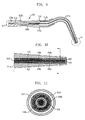
FIG. 1 is a perspective view of a conventional endodontic instrument for root canal filling, and FIG. 2 is a sectional view of a heating tip in the conventional endodontic instrument for root canal filling illustrated in FIG. 1. Referring to FIGS. 1 and 2, the conventional endodontic filling instrument 100 includes a heating tip 110, a handpiece 120, a cable 130, and a control box 140. The control box 140 includes a power switch 142, a control panel 141, and a display (not shown) for displaying an operation state of the filling instrument 100. The handpiece 120 is connected to the heating tip 110 for supplying heat to gutta-percha to melt or cut the gutta-percha. The handpiece 120 and the control box 140 are connected to each other by the cable 130. Electric power required by the handpiece 120 is supplied from the control box 140 via the cable 30.
The heating tip 110 includes a heat generating core 114, an insulating film 112 enclosing the heat generating core 114, and a conical resistant heat generating layer 111 having a cross-sectional area gradually reduced toward a front end 113 of the heat generating core 114. The front end 113 of the heat generating core 114 is connected to the resistant heat generating layer 111 because it is not enclosed by the insulating film 112.
Accordingly, when a current flows through the resistant heat generating layer 111 and the heat generating core 114, a current density increases at the front end 113 where the heat generating core 114 and the resistant heat generating layer 111 are connected to each other, thus generating more heat than any portion.
However, the above-mentioned conventional filling instrument has a problem in that there is inconvenience in carrying the filling instrument because the control box and the handpiece are separate from each other. Further, the heating tip has poor heating efficiency.
DISCLOSURE Technical Problem
An embodiment of the present invention is directed to providing an endodontic filling instrument having excellent heat generation efficiency. Specifically, the endodontic instrument for root canal filling includes a heating tip having a first metal part, a second metal part, and a third metal part. The first metal part is a resistant tube. The second metal part supplies electric power, checks a thermoelectric power (+) terminal, and serves as a (+) terminal of the thermocouple. The third metal part supplies electric power and serves as a (−) terminal of the thermocouple. The second metal part and the third metal part contact each other at a position spaced apart from an end of the heating tip by a predetermined distance. A thermoelectric power is generated at the contact part. Accordingly, endodontic filling instrument can detect temperature using the thermoelectric power of the thermocouple of the second and third metal parts.
Other objects and advantages of the present invention can be understood by the following description, and become apparent with reference to the embodiments of the present invention. Also, it is obvious to those skilled in the art of the present invention that the objects and advantages of the present invention can be realized by the means as claimed and combinations thereof.
Technical Solution
In accordance with an aspect of the present invention, there is provided an endodontic instrument for root canal filling, which includes: a body including a DC power source and a printed circuit board; a heating tip connected to the body, the heating tip including a first metal part serving as a resistant tube, a second metal part and a third metal part forming a thermocouple, and an insulator enclosing the second metal part and the third metal part; a switch for operating the heating tip; and a control circuit for switching on/off the supply of a voltage applied to the heating tip.
In accordance with another aspect of the present invention, there is provided a heating tip of an endodontic instrument for root canal filling, which includes: a first metal part serving as a resistant tube; a second metal part disposed inside the first metal part, formed of a material having a small electric resistance, and configured to supply electric power, check a thermoelectric power (+) terminal, and serve as a (+) terminal of a thermocouple; a third metal part disposed inside the first metal part, and configured to supply electric power and serve as a (−) terminal of the thermocouple; a contact part in which one end of the second metal part and the third metal part contact each other; an insulator disposed inside the first metal part and enclosing surfaces of the second metal part and the third metal part; a first conductive tube contacting the other end of the second metal part; a second conductive tube contacting the other end of the third metal part; and an insulator connected and fixed to the first and second conductive tubes, whereby temperature is detected using the thermoelectric power of the thermocouple of the second and third metal parts.
Advantageous Effects
The embodiments of the present invention provide an endodontic instrument for root canal filling, which has excellent heat generation, and a heating tip adapted to the same. The endodontic instrument for root canal filling includes: a heating tip having a first metal part serving as a resistant tube, a second metal part and a third metal part forming a thermocouple, and an insulator enclosing the second metal part and the third metal part; and a control circuit for switching on/off the power supply applied to the heating tip. Further, a heating tip of an endodontic instrument for root canal filling includes: a first metal part serving as a resistant tube; a second metal part disposed inside the first metal part, formed of a metal having low electric resistance, and configured to supply electric power, check a thermoelectric power (+) terminal, and serve as a (+) terminal of a thermocouple; a third metal part disposed inside the first metal part, and configured to supply electric power and serve as a (−) terminal of the thermocouple; a contact part in which one end of the second metal part and the third metal part contact each other; an insulator disposed inside the first metal part and enclosing surfaces of the second metal part and the third metal part; a first conductive tube contacting the other end of the second metal part; a second conductive tube contacting the other end of the third metal part; and an insulator connected and fixed to the first and second conductive tubes. Accordingly, the heating tip can detect temperature using a thermoelectric power of the thermocouple of the second and third metal parts.
BRIEF DESCRIPTION OF THE DRAWINGS
FIG. 1 is a perspective view of a conventional endodontic instrument for root canal filling.
FIG. 2 is a sectional view of a heating tip in the conventional endodontic instrument for root canal filling illustrated in FIG. 1.
FIG. 3 is a perspective view of an endodontic instrument for root canal filling in accordance with an embodiment of the present invention.
FIG. 4 is a partial sectional view illustrating a front end of a heating tip in FIG. 3 in accordance with an embodiment of the present invention.
FIG. 5 is a partial sectional view illustrating a front end of a heating tip in FIG. 3 in accordance with another embodiment of the present invention.
FIG. 6 is a sectional view illustrating a rear end of a heating tip in FIG. 3.
FIG. 7 is a sectional view taken along line A-A′ of FIG. 4 in accordance with an embodiment of the present invention.
FIG. 8 is a sectional view taken along line A-A′ of FIG. 4 in accordance with another embodiment of the present invention.
FIG. 9 is a sectional view of an endodontic instrument for root canal filling in accordance with another embodiment of the present invention.
FIG. 10 is a detailed sectional view of an end portion (B) of a heating tip illustrated in FIG. 9.
FIG. 11 is a sectional view of the heating tip, taken along line A-A′ of FIG. 10.
FIG. 12 is a circuit diagram of a control circuit for controlling heating and temperature measurement in a heating tip of the endodontic instrument for root canal filling.
BEST MODE FOR THE INVENTION
The advantages, features and aspects of the invention will become apparent from the following description of the embodiments with reference to the accompanying drawings, which is set forth hereinafter.
Hereinafter, the configuration, function and effect of an endodontic instrument for root canal filling in accordance with the embodiments of the present invention will be described below with reference to FIGS. 3 to 5.
FIG. 3 is a perspective view of an endodontic instrument for root canal filling in accordance with an embodiment of the present invention. Referring to FIG. 3, the endodontic filling instrument 200 has a pen-shaped body 220 so that an operator can easily grasp it. In addition, the endodontic filling instrument 200 includes a heating tip 210, a switch 230, a display 240, and a light emitter 250. The body 220 includes a DC power source and a main printed circuit board arranged therein.
The heating tip 210 extends forwardly from the body 220 and generates heat to melt gutta-percha disposed at a desired position and thus fill a root canal with the melt gutta-percha. The display 240 displays an operation state of the heating tip 210 and is manipulated using an operation condition setting button 241, e.g., a power switch or temperature control switch.
The heating tip 210 is operated using the switches 230 and 231. Further, the light emitter 250 may be installed on a front end portion of the body 220 to illuminate an affected part to be treated. A battery charging terminal 242 is formed in the body 220.
FIG. 4 is a sectional view illustrating the front end of the heating tip in FIG. 3 in accordance with an embodiment of the present invention. FIG. 5 is a sectional view illustrating the front end of the heating tip in FIG. 3 in accordance with another embodiment of the present invention. FIG. 6 is a sectional view illustrating the rear end of the heating tip in FIG. 3. FIG. 7 is a sectional view taken along line A-A′ of FIG. 4 in accordance with an embodiment of the present invention. FIG. 8 is a sectional view taken along line A-A′ of FIG. 4 in accordance with another embodiment of the present invention.
Referring to FIG. 4, the heating tip 210 includes a first metal part 211 a, a second metal part 212, a third metal part 213, and an insulator 214.
The first metal part 211 a is a resistant tube and is formed of any one selected from the group consisting of nickel, nickel alloy, titanium alloy and a combination thereof. The second metal part 212 is disposed inside the first metal part 211 a. The second metal part 212 supplies electric power, checks a thermoelectric power (+) terminal, serves as a (+) terminal of a thermocouple, and is formed of a metal having low electric resistance, e.g., copper, copper alloy, silver alloy or a combination thereof. The third metal part 213 is disposed inside the first metal part 211 a. The third metal part 213 supplies electric power and serves as a (−) terminal of the thermocouple. The third metal part 213 is formed of nickel or nickel alloy.
When the sectional areas of the second metal part 212 and the third metal part 213 increase and electric power is supplied thereto, the resistance is small and the second metal part 212 and the third metal part 213 generate low heat. Further, high heat is generated from the surface of the first metal part 211 a and a coating of the insulator is protected.
The insulator 214 a is disposed inside the first metal part 211 a and encloses the second metal part 212 and the third metal part 213. The insulator 214 a is formed of ceramic epoxy or enamel. The second metal part 212 and the third metal part 213 may form a contact part 215, i.e., a thermocouple junction, at a position spaced apart from the end 216 of the heating tip 210 by a predetermined distance. The contact part 215, i.e., the thermocouple junction, may be formed at the end 216 of the heating tip 210 to generate a thermoelectric power. Further, the contact part 215 may be formed at a position located 0.5-1.0 mm inwardly from the end of the heating tip by a spot or the like. The first metal part 211 a may have a tapered shape with a thickness of 0.5 to 1.0 mm. Further, the third metal part 213 and the first metal part 211 a contact each other at the end of the heating tip 210.
Referring to FIG. 5, the second metal part 212 and the third metal part 213 may contact each other at the end of the heating tip 210.
Referring to FIG. 6, first and second conductive tubes 218 a and 218 b are disposed at a rear end of the heating tip 210. The second metal part 212 contacts the first conductive tube 218 a to form a thermocouple terminal 217 a. The thermocouple terminal 217 a may be formed by a spot or soldering.
The third metal part 213 contacts the second conductive tube 218 b to form a thermocouple terminal 217 b. The thermocouple terminal 217 b may be formed by a spot or soldering. The first and second conductive tubes 218 a and 218 b are connected and fixed to the insulator 214 b in a straight line. The first metal part 211 b may be further provided at the rear end of the heating tip 210 in order to generate heat at a portion where a large amount of electric power is supplied.
Referring to FIGS. 7 and 8, the second metal part 212 and the third metal part 213 disposed inside the first metal part 211 may have cross-sections of semicircular or circular shapes facing each other. The insulator 214 a insulates the first metal part 211 a, the second metal part 212, and the third metal part 213 from contacting one another.
FIG. 9 is a sectional view of an endodontic instrument for root canal filling in accordance with another embodiment of the present invention, and FIG. 10 is a detailed sectional view of an end portion (B) of a heating tip illustrated in FIG. 9. Referring to FIGS. 5 and 10, the heating tip 310 includes first metal parts 311 a and 311 b, a second metal part 312, a third metal part 313, a thermocouple junction 315, first and second conductive tubes 318 a and 318 b, and insulators 314 a, 314 b, 319 a and 319 b.
The first metal parts 311 a and 311 b are resistant tubes. The first metal part 311 a may be formed of nickel alloy. The third metal part 313 is provided in a tube type and disposed inside the first metal part. The third metal part 313 supplies electric power and serves a (−) terminal of a thermocouple.
The third metal part 313 may be formed of nickel or nickel alloy. The second metal part 312 is provided in a wire type and disposed inside the third metal part 313. The second metal part 312 supplies electric power, checks a thermoelectric power (+) terminal, and serves as a (+) terminal of the thermocouple. The second metal part 312 may be formed of copper or copper alloy.
FIG. 11 is a sectional view of the heating tip, taken along line A-A′ of FIG. 10. Referring to FIG. 11, an insulator 319 a, which is a ceramic epoxy, is disposed around a periphery of the wire-type second metal part 312, and a insulator 319 b is disposed around a periphery of the third metal part 313.
A thermocouple junction where the end of the second metal part 312 and the end of the third metal part 313 contact each other is formed in an end portion 320 of the heating tip. A heating power is checked through the thermocouple junction.
In addition, the first conductive tube 318 a serves as a terminal contacting the second metal part 312. The first conductive tube 318 a and the second metal part 312 contact each other by the thermocouple terminal 317. The second conductive tube 318 b serves as a terminal contacting the third metal part 313.
The heating tips 210 and 310 in accordance with the embodiments of the present invention may be formed in a curved shape, such as an L-shape, as illustrated in FIGS. 3 and 9.
FIG. 12 is a circuit diagram of a control circuit for controlling the heating and the temperature measurement in the heating tip of the endodontic instrument for root canal filling. Referring to FIG. 12, the control circuit includes a heater, a switch SW, a heater driver 400, an amplifier 600, and a comparator 500. The heater includes a resistant tube wire 1(S) serving as the first metal part of the heating tip, a thermocouple wire 3(A) serving as the second metal part, and a conductive wire 2(C) serving as the third metal part.
The switch SW switches on/off the electric power supply to the heating tip. The heater driver 400 supplies the electric power to the heating tip. The amplifier 600 amplifies a slight voltage generated from the contact part of the heating tip. The comparator 500 compares the amplified voltage with a set temperature.
The heating of the heating tip is performed by switching off the switch SW and applying an alternating current (AC) voltage to one terminal comprised of the thermocouple wire 3(A) and the conductive wire 2(C), and another terminal comprised of the resistant tube wire 1(S). In this case, heat is generated at the contact part 215 of the heating tip and the end of the first metal part. After a predetermined time elapses, the supply of the voltage applied to the heater driver 400 is stopped and the switch SW is then turned on.
Due to the voltage that has been already applied, the temperature around the end of the heating tip is increased. A small voltage is generated from the contact part 215 by the thermoelectric power. The small voltage is transferred through the amplifier 600 to the comparator 500 and is compared with the set temperature. A voltage is applied to the heater driver 400 and the temperature is again measured. By repeating these procedures, the current is adjusted such that the heating tip reaches the set temperature.
The present application contains subject matter related to Korean Patent Application Nos. 10-2006-0101541 and 10-2006-0111242, filed in the Korean Intellectual Property Office on Oct. 18, 2006, and Nov. 10, 2006, the entire contents of which is incorporated herein by reference.
While the present invention has been described with respect to the specific embodiments, it will be apparent to those skilled in the art that various changes and modifications may be made without departing from the spirit and scope of the invention as defined in the following claims.

Claims (6)

1. An endodontic instrument for root canal filling, comprising:
a body including a direct current (DC) power source and a printed circuit board;
a heating tip connected to the body;
a switch for operating the heating tip; and
a control circuit for switching on/off power supply applied to the heating tip,
wherein the heating tip includes:
a first metal part serving as a resistant tube;
a third metal part provided in a tube type and disposed inside the first metal part and configured to supply thermoelectric power and serve as a (−) terminal of a thermocouple;
a second metal part disposed inside the third metal part in a form of wire and configured to supply the thermoelectric power, check a thermoelectric power (+) terminal, and serve as a (+) terminal of the thermocouple;
a thermocouple junction in which one end of the second metal part and one end of the third metal part contact each other;
a first insulator disposed inside the first metal part and enclosing a surface of the third metal part;
a second insulator disposed inside the third metal part and enclosing a surface of the second metal part;
a first conductive tube contacting the other end of the second metal part;
a second conductive tube contacting the other end of the third metal part; and
a third insulator connected and fixed to the first and second conductive tubes, wherein temperature is detected using the thermoelectric power of the thermocouple of the second and third metal parts.
2. The endodontic filling instrument of claim 1, wherein the second metal part supplies electric power, checks a thermoelectric power (+) terminal, and serves as a (+) terminal of the thermocouple, and the third metal part supplies electric power, and serves as a (−) terminal of the thermocouple.
3. The endodontic filling instrument of claim 1, wherein the first metal part is formed of any one selected from the group consisting of nickel, nickel alloy, titanium alloy and a combination thereof;
the second metal part is formed of any one selected from the group consisting of copper, copper alloy, silver alloy and a combination thereof;
the third metal part is formed of nickel or nickel alloy; and
the insulator is formed of ceramic epoxy, enamel, or a combination thereof.
4. The endodontic filling instrument of claim 2, wherein the thermocouple of the second metal part and the third metal part is at an end of the heating tip.
5. The endodontic filling instrument of claim 1, wherein the control circuit includes:
a heater including a resistant tube wire serving as the first metal part of the heating tip, a conductive wire serving as the third metal part, and a thermocouple wire serving as the second metal part;
a switch for switching power supply applied to the heating tip;
a heater driver for supplying electric power to the heating tip;
an amplifier for amplifying a small voltage generated from the thermocouple; and
a comparator for comparing the amplified voltage with a set temperature.
6. A heating tip of an endodontic instrument for root canal filling, comprising:
a first metal part serving as a resistant tube;
a third metal part provided in a tube type and disposed inside the first metal part and configured to supply thermoelectric power and serve as a (−) terminal of a thermocouple;
a second metal part disposed inside the third metal part in a form of wire and configured to supply the thermoelectric power, check a thermoelectric power (+) terminal, and serve as a (+) terminal of the thermocouple;
a thermocouple junction in which one end of the second metal part and one end of the third metal part contact each other;
a first insulator disposed inside the first metal part and enclosing a surface of the third metal part;
a second insulator disposed inside the third metal part and enclosing a surface of the second metal part;
a first conductive tube contacting the other end of the second metal part;
a second conductive tube contacting the other end of the third metal part; and
a third insulator connected and fixed to the first and second conductive tubes, wherein temperature is detected using the thermoelectric power of the thermocouple of the second and third metal parts.
US12/446,301 2006-10-18 2007-10-18 Endodontic instrument for root canal filling and heating tip adapted to the same Active 2028-04-21 US8215955B2 (en)

Applications Claiming Priority (5)

Application Number Priority Date Filing Date Title
KR20060101541 2006-10-18
KR10-2006-0101541 2006-10-18
KR20060111242 2006-11-10
KR10-2006-0111242 2006-11-10
PCT/KR2007/005103 WO2008048054A1 (en) 2006-10-18 2007-10-18 Endodontic instrument for root canal filling and heating tip adapted to the same

Publications (2)

Publication Number Publication Date
US20100297571A1 US20100297571A1 (en) 2010-11-25
US8215955B2 true US8215955B2 (en) 2012-07-10

Family

ID=39314232

Family Applications (1)

Application Number Title Priority Date Filing Date
US12/446,301 Active 2028-04-21 US8215955B2 (en) 2006-10-18 2007-10-18 Endodontic instrument for root canal filling and heating tip adapted to the same

Country Status (7)

Country Link
US (1) US8215955B2 (en)
EP (1) EP2073741A4 (en)
JP (1) JP4921559B2 (en)
KR (1) KR100959404B1 (en)
CN (1) CN101563045B (en)
CA (1) CA2667054C (en)
WO (1) WO2008048054A1 (en)

Cited By (4)

* Cited by examiner, † Cited by third party
Publication number Priority date Publication date Assignee Title
USD842474S1 (en) 2017-10-20 2019-03-05 Ormco Corporation Endodontic file
US10285754B2 (en) 2015-05-18 2019-05-14 Biosense Webster (Israel) Ltd. Catheter with coaxial thermocouple
US10543060B2 (en) 2015-12-03 2020-01-28 Ormco Corporation Fluted endodontic file
US11033357B1 (en) 2020-11-12 2021-06-15 King Abdulaziz University Methods for tooth extraction using a thermoelectric device

Families Citing this family (7)

* Cited by examiner, † Cited by third party
Publication number Priority date Publication date Assignee Title
KR101196446B1 (en) * 2010-04-16 2012-11-01 비엔엘바이오테크 주식회사 Thermal tester for dental clinic
WO2012142231A2 (en) 2011-04-15 2012-10-18 Endodontic Specialist's Advocate, Llc Endodontic obturation system and method
KR101912850B1 (en) 2011-06-19 2018-10-30 비아멧 파마슈티컬즈(엔씨), 인코포레이티드 Metalloenzyme inhibitor compounds
US10221160B2 (en) 2012-01-20 2019-03-05 Mycovia Pharmaceuticals, Inc. Metalloenzyme inhibitor compounds
CN104173113A (en) * 2014-09-18 2014-12-03 张晓飞 Pulp vitality temperature detector
WO2019076330A1 (en) * 2017-10-19 2019-04-25 上海交通大学医学院附属第九人民医院 Digitized evaluation method and system for quality of in-vitro root canal preparation
KR102404233B1 (en) * 2019-11-28 2022-06-02 (주)디엑스엠 Ball heating tip for dental treatment instrument

Citations (10)

* Cited by examiner, † Cited by third party
Publication number Priority date Publication date Assignee Title
US3919775A (en) 1971-12-30 1975-11-18 Oscar Malmin Endodontic sealing system and apparatus
US4353698A (en) * 1979-12-20 1982-10-12 Inventive Technology International, Inc. Dental tool
US5393350A (en) * 1993-10-08 1995-02-28 Schroeder; Jon M. Thermoelectric generator and magnetic energy storage unit
US5495093A (en) * 1993-02-05 1996-02-27 Edsyn, Inc. Soldering apparatus processor having temperature selection, calibration and heating control of tip
US5752825A (en) 1994-04-28 1998-05-19 Buchanan; Leonard Stephen Endodontic treatment system
US5893713A (en) * 1997-12-04 1999-04-13 Kerr Manufacturing Company Dental probe having superelastic plugger element and method of use thereof
US6285010B1 (en) * 1999-03-26 2001-09-04 Kabushiki Kaisha Kobe Seiko Sho (Kobe Steel, Ltd.) Method and device for high-temperature, high-pressure treatment of semiconductor wafer
KR20040006371A (en) 2002-07-12 2004-01-24 주식회사 메타바이오메드 Complex root canal plugger for dental clinic
US6910887B2 (en) * 2000-02-24 2005-06-28 Megadent Endo Products, B.V. Device for performing an endodontic treatment
US6981868B2 (en) * 2000-11-09 2006-01-03 J. Morita Manufacturing Corporation Dental filling instrument and attachment therefor

Family Cites Families (12)

* Cited by examiner, † Cited by third party
Publication number Priority date Publication date Assignee Title
US5043560A (en) * 1989-09-29 1991-08-27 Masreliez C Johan Temperature control of a heated probe
JPH10216149A (en) * 1997-02-06 1998-08-18 Kanetoshi Fukuda High frequency hair-removing needle and its contamination removing method
JP3124506B2 (en) * 1997-03-14 2001-01-15 白光株式会社 Heater / sensor complex
US5935124A (en) * 1997-12-02 1999-08-10 Cordis Webster, Inc. Tip electrode with multiple temperature sensors
US6312254B1 (en) * 2000-09-22 2001-11-06 Joshua Friedman Dispenser for heating and extruding dental material
JP2003323219A (en) * 2002-01-22 2003-11-14 Thermo Solution:Kk Temperature regulator
JP2004065529A (en) * 2002-08-06 2004-03-04 Takayuki Sato Blood pressure controlling apparatus
US7008222B2 (en) * 2003-06-24 2006-03-07 Suk Song Oh Root canal plugging apparatus for dental work
KR200350517Y1 (en) 2004-02-12 2004-05-17 비엔엘바이오테크 주식회사 Wireless type device for dental treatment of root canal obturation
KR200382194Y1 (en) 2004-12-29 2005-04-19 대륭전자(주) A endodontic treatment gutta percha cutter for dental
EP1863397A4 (en) * 2005-03-28 2010-11-03 Bnl Biotech Co Ltd Wireless recharger of complete melting type for endodontic treatment
KR100617897B1 (en) 2006-05-11 2006-09-06 이광석 Filled injection tip for teeth treatment

Patent Citations (10)

* Cited by examiner, † Cited by third party
Publication number Priority date Publication date Assignee Title
US3919775A (en) 1971-12-30 1975-11-18 Oscar Malmin Endodontic sealing system and apparatus
US4353698A (en) * 1979-12-20 1982-10-12 Inventive Technology International, Inc. Dental tool
US5495093A (en) * 1993-02-05 1996-02-27 Edsyn, Inc. Soldering apparatus processor having temperature selection, calibration and heating control of tip
US5393350A (en) * 1993-10-08 1995-02-28 Schroeder; Jon M. Thermoelectric generator and magnetic energy storage unit
US5752825A (en) 1994-04-28 1998-05-19 Buchanan; Leonard Stephen Endodontic treatment system
US5893713A (en) * 1997-12-04 1999-04-13 Kerr Manufacturing Company Dental probe having superelastic plugger element and method of use thereof
US6285010B1 (en) * 1999-03-26 2001-09-04 Kabushiki Kaisha Kobe Seiko Sho (Kobe Steel, Ltd.) Method and device for high-temperature, high-pressure treatment of semiconductor wafer
US6910887B2 (en) * 2000-02-24 2005-06-28 Megadent Endo Products, B.V. Device for performing an endodontic treatment
US6981868B2 (en) * 2000-11-09 2006-01-03 J. Morita Manufacturing Corporation Dental filling instrument and attachment therefor
KR20040006371A (en) 2002-07-12 2004-01-24 주식회사 메타바이오메드 Complex root canal plugger for dental clinic

Cited By (5)

* Cited by examiner, † Cited by third party
Publication number Priority date Publication date Assignee Title
US10285754B2 (en) 2015-05-18 2019-05-14 Biosense Webster (Israel) Ltd. Catheter with coaxial thermocouple
US10918437B2 (en) 2015-05-18 2021-02-16 Biosense Webster (Israel) Ltd. Catheter with coaxial thermocouple
US10543060B2 (en) 2015-12-03 2020-01-28 Ormco Corporation Fluted endodontic file
USD842474S1 (en) 2017-10-20 2019-03-05 Ormco Corporation Endodontic file
US11033357B1 (en) 2020-11-12 2021-06-15 King Abdulaziz University Methods for tooth extraction using a thermoelectric device

Also Published As

Publication number Publication date
KR20080035490A (en) 2008-04-23
CA2667054A1 (en) 2008-04-24
JP2010506652A (en) 2010-03-04
JP4921559B2 (en) 2012-04-25
EP2073741A4 (en) 2013-07-24
CA2667054C (en) 2011-05-10
EP2073741A1 (en) 2009-07-01
WO2008048054A1 (en) 2008-04-24
KR100959404B1 (en) 2010-05-25
CN101563045A (en) 2009-10-21
CN101563045B (en) 2012-07-04
US20100297571A1 (en) 2010-11-25

Similar Documents

Publication Publication Date Title
US8215955B2 (en) Endodontic instrument for root canal filling and heating tip adapted to the same
US7677892B2 (en) Method and extractor for removing a tool fragment from a tooth root canal
US9033706B2 (en) Wireless recharger of complete melting type for endodontic treatment
US20110165537A1 (en) Dental obturation system
US20040009452A1 (en) Complex root canal plugging apparatus for dental work
US20100087834A1 (en) Bipolar instrument and method for endoscopic controlled shortening and/or fragmentation of stents arranged in gastrointestinal tract in the tracheobronchial system or in other hollow organs
US11779436B2 (en) Plasma jet device
US20080193895A1 (en) Wireless Recharger For Back Filler On Endodontic Treatment
US20070218420A1 (en) Endodontic instrument with non-conductive coating and method for locating the apex of a tooth
US7008222B2 (en) Root canal plugging apparatus for dental work
KR20060122195A (en) Complete melting type wireless charger for endodontic treatment
KR100317420B1 (en) Gutta percha point-cutting apparatus
KR200350517Y1 (en) Wireless type device for dental treatment of root canal obturation
CN209864101U (en) Single-handle hot gutta-percha filling instrument
KR102631436B1 (en) Handpiece with root canal length measurement function
JPH1132990A (en) Dental mirror
JPWO2008047490A1 (en) Dental equipment
Kimura et al. Histopathological study of the effects of Er: YAG laser irradiation on root canals in rats
WO2005067809A1 (en) Complex root canal plugger for dental clinic
RU99100329A (en) HIGH FREQUENCY ELECTRIC CURRENT DEVICE FOR TEETH DEVITALIZATION

Legal Events

Date Code Title Description
AS Assignment

Owner name: BNL BIOTECH CO., LTD., KOREA, REPUBLIC OF

Free format text: ASSIGNMENT OF ASSIGNORS INTEREST;ASSIGNOR:LEE, IN-WHAN;REEL/FRAME:023268/0083

Effective date: 20090417

STCF Information on status: patent grant

Free format text: PATENTED CASE

FPAY Fee payment

Year of fee payment: 4

MAFP Maintenance fee payment

Free format text: PAYMENT OF MAINTENANCE FEE, 8TH YR, SMALL ENTITY (ORIGINAL EVENT CODE: M2552); ENTITY STATUS OF PATENT OWNER: SMALL ENTITY

Year of fee payment: 8

MAFP Maintenance fee payment

Free format text: PAYMENT OF MAINTENANCE FEE, 12TH YR, SMALL ENTITY (ORIGINAL EVENT CODE: M2553); ENTITY STATUS OF PATENT OWNER: SMALL ENTITY

Year of fee payment: 12