US8211593B2 - Low platinum fuel cells, catalysts, and method for preparing the same - Google Patents
Low platinum fuel cells, catalysts, and method for preparing the same Download PDFInfo
- Publication number
- US8211593B2 US8211593B2 US11/303,476 US30347605A US8211593B2 US 8211593 B2 US8211593 B2 US 8211593B2 US 30347605 A US30347605 A US 30347605A US 8211593 B2 US8211593 B2 US 8211593B2
- Authority
- US
- United States
- Prior art keywords
- nanoparticles
- composition
- thin film
- carbon
- catalyst
- Prior art date
- Legal status (The legal status is an assumption and is not a legal conclusion. Google has not performed a legal analysis and makes no representation as to the accuracy of the status listed.)
- Expired - Fee Related, expires
Links
Images


Classifications
-
- H—ELECTRICITY
- H01—ELECTRIC ELEMENTS
- H01B—CABLES; CONDUCTORS; INSULATORS; SELECTION OF MATERIALS FOR THEIR CONDUCTIVE, INSULATING OR DIELECTRIC PROPERTIES
- H01B1/00—Conductors or conductive bodies characterised by the conductive materials; Selection of materials as conductors
- H01B1/06—Conductors or conductive bodies characterised by the conductive materials; Selection of materials as conductors mainly consisting of other non-metallic substances
- H01B1/12—Conductors or conductive bodies characterised by the conductive materials; Selection of materials as conductors mainly consisting of other non-metallic substances organic substances
- H01B1/122—Ionic conductors
-
- B—PERFORMING OPERATIONS; TRANSPORTING
- B82—NANOTECHNOLOGY
- B82Y—SPECIFIC USES OR APPLICATIONS OF NANOSTRUCTURES; MEASUREMENT OR ANALYSIS OF NANOSTRUCTURES; MANUFACTURE OR TREATMENT OF NANOSTRUCTURES
- B82Y30/00—Nanotechnology for materials or surface science, e.g. nanocomposites
-
- H—ELECTRICITY
- H01—ELECTRIC ELEMENTS
- H01B—CABLES; CONDUCTORS; INSULATORS; SELECTION OF MATERIALS FOR THEIR CONDUCTIVE, INSULATING OR DIELECTRIC PROPERTIES
- H01B1/00—Conductors or conductive bodies characterised by the conductive materials; Selection of materials as conductors
- H01B1/04—Conductors or conductive bodies characterised by the conductive materials; Selection of materials as conductors mainly consisting of carbon-silicon compounds, carbon or silicon
-
- H—ELECTRICITY
- H01—ELECTRIC ELEMENTS
- H01M—PROCESSES OR MEANS, e.g. BATTERIES, FOR THE DIRECT CONVERSION OF CHEMICAL ENERGY INTO ELECTRICAL ENERGY
- H01M4/00—Electrodes
- H01M4/86—Inert electrodes with catalytic activity, e.g. for fuel cells
- H01M4/88—Processes of manufacture
- H01M4/8825—Methods for deposition of the catalytic active composition
-
- H—ELECTRICITY
- H01—ELECTRIC ELEMENTS
- H01M—PROCESSES OR MEANS, e.g. BATTERIES, FOR THE DIRECT CONVERSION OF CHEMICAL ENERGY INTO ELECTRICAL ENERGY
- H01M4/00—Electrodes
- H01M4/86—Inert electrodes with catalytic activity, e.g. for fuel cells
- H01M4/88—Processes of manufacture
- H01M4/8878—Treatment steps after deposition of the catalytic active composition or after shaping of the electrode being free-standing body
- H01M4/8892—Impregnation or coating of the catalyst layer, e.g. by an ionomer
-
- H—ELECTRICITY
- H01—ELECTRIC ELEMENTS
- H01M—PROCESSES OR MEANS, e.g. BATTERIES, FOR THE DIRECT CONVERSION OF CHEMICAL ENERGY INTO ELECTRICAL ENERGY
- H01M4/00—Electrodes
- H01M4/86—Inert electrodes with catalytic activity, e.g. for fuel cells
- H01M4/90—Selection of catalytic material
-
- H—ELECTRICITY
- H01—ELECTRIC ELEMENTS
- H01M—PROCESSES OR MEANS, e.g. BATTERIES, FOR THE DIRECT CONVERSION OF CHEMICAL ENERGY INTO ELECTRICAL ENERGY
- H01M4/00—Electrodes
- H01M4/86—Inert electrodes with catalytic activity, e.g. for fuel cells
- H01M4/90—Selection of catalytic material
- H01M4/9075—Catalytic material supported on carriers, e.g. powder carriers
- H01M4/9083—Catalytic material supported on carriers, e.g. powder carriers on carbon or graphite
-
- H—ELECTRICITY
- H01—ELECTRIC ELEMENTS
- H01M—PROCESSES OR MEANS, e.g. BATTERIES, FOR THE DIRECT CONVERSION OF CHEMICAL ENERGY INTO ELECTRICAL ENERGY
- H01M4/00—Electrodes
- H01M4/86—Inert electrodes with catalytic activity, e.g. for fuel cells
- H01M4/90—Selection of catalytic material
- H01M4/92—Metals of platinum group
- H01M4/921—Alloys or mixtures with metallic elements
-
- H—ELECTRICITY
- H01—ELECTRIC ELEMENTS
- H01M—PROCESSES OR MEANS, e.g. BATTERIES, FOR THE DIRECT CONVERSION OF CHEMICAL ENERGY INTO ELECTRICAL ENERGY
- H01M4/00—Electrodes
- H01M4/86—Inert electrodes with catalytic activity, e.g. for fuel cells
- H01M4/90—Selection of catalytic material
- H01M4/92—Metals of platinum group
- H01M4/925—Metals of platinum group supported on carriers, e.g. powder carriers
- H01M4/926—Metals of platinum group supported on carriers, e.g. powder carriers on carbon or graphite
-
- H—ELECTRICITY
- H01—ELECTRIC ELEMENTS
- H01M—PROCESSES OR MEANS, e.g. BATTERIES, FOR THE DIRECT CONVERSION OF CHEMICAL ENERGY INTO ELECTRICAL ENERGY
- H01M8/00—Fuel cells; Manufacture thereof
- H01M8/10—Fuel cells with solid electrolytes
- H01M2008/1095—Fuel cells with polymeric electrolytes
-
- Y—GENERAL TAGGING OF NEW TECHNOLOGICAL DEVELOPMENTS; GENERAL TAGGING OF CROSS-SECTIONAL TECHNOLOGIES SPANNING OVER SEVERAL SECTIONS OF THE IPC; TECHNICAL SUBJECTS COVERED BY FORMER USPC CROSS-REFERENCE ART COLLECTIONS [XRACs] AND DIGESTS
- Y02—TECHNOLOGIES OR APPLICATIONS FOR MITIGATION OR ADAPTATION AGAINST CLIMATE CHANGE
- Y02E—REDUCTION OF GREENHOUSE GAS [GHG] EMISSIONS, RELATED TO ENERGY GENERATION, TRANSMISSION OR DISTRIBUTION
- Y02E60/00—Enabling technologies; Technologies with a potential or indirect contribution to GHG emissions mitigation
- Y02E60/30—Hydrogen technology
- Y02E60/50—Fuel cells
Definitions
- This invention is in the field of electrochemical catalysts used in fuel cells (e.g., in polymer electrolyte membrane (PEM) fuel cells).
- the invention is related to the reduction of the platinum contents and the improvement of the catalytic efficiency by innovative catalyst compositions and nanostructures at the interfaces, or inside a gas micro distribution (microdiffusion) layer, between the electrodes and the polymer electrolyte (PEM) comprising the fuel cell.
- PEM polymer electrolyte membrane
- Fuel cells combine hydrogen and oxygen without combustion to form water and to produce direct electric current. The process can be described as electrolysis in reverse. Fuel cells have potential for stationary and portable power applications; however, the commercial viability of fuel cells for power generation in stationary and portable applications depends upon solving a number of manufacturing, cost, and durability problems.
- Electrochemical fuel cells convert fuel and an oxidant into electricity and a reaction product.
- a typical fuel cell consists of a membrane and two electrodes,—a cathode and an anode. The membrane is sandwiched between the cathode and anode.
- Fuel in the form of hydrogen, is supplied to the anode, where a catalyst, such as platinum and its alloys, catalyzes the following reaction: 2H 2 ⁇ 4H + +4e ⁇ .
- Polymer electrolyte fuel cells have improved significantly in the past few years both with respect to efficiency and with respect to practical fuel cell design. Some prototypes of fuel-cell replacements for portable batteries and for automobile batteries have been demonstrated. However, problems associated with the cost, activity, and stability of the electrocatalysts are major concerns in the development of the polymer electrolyte fuel cell. For example, platinum (Pt)-based catalysts are the most successful catalysts for fuel cell and other catalytic applications. Unfortunately, the high cost and scarcity of platinum has limited the use of this material in large-scale applications.
- noble metals and non-noble metals can be used as catalysts in the form of Pt alloys.
- the noble metals such as Pd, Rh, Ir, Ru, Os, Au, etc have been investigated.
- the non-noble metals including Sn, W, Cr, Mn, Fe, Co, Ni, Cu, etc (U.S. Pat. No. 6,562,499) has also been tried.
- Different Pt-alloys were disclosed as catalysts for fuel cell applications.
- Binary Alloys useful as catalysts include Pt—Cr (U.S. Pat. No. 4,316,944), Pt—V (U.S. Pat. No. 4,202,934), Pt—Ta (U.S. Pat.
- Pt—Cu U.S. Pat. No. 4,716,087
- Pt—Ru U.S. Pat. No. 6,007,934
- Pt—Y U.S. Pat. No. 4,031,291
- Ternary alloys useful as catalysts include Pt—Ru—Os (U.S. Pat. No. 5,856,036), Pt—Ni—Co, Pt—Cr—C, Pt—Cr—Ce (U.S. Pat. No. 5,079,107), Pt—Co—Cr (U.S. Pat. No. 4,711,829), Pt—Fe—Co (U.S. Pat. No.
- Pt—Ru—Ni U.S. Pat. No. 6,517,965
- Pt—Ga—Cr Co, Ni (U.S. Pat. No. 4,880,711)
- Pt—Co—Cr U.S. Pat. No. 4,447,506
- Quaternary Alloys useful as catalysts includes Pt—Ni—Co—Mn (U.S. Pat. No. 5,225,391), Pt—Fe—Co—Cu (U.S. Pat. No. 5,024,905), etc.
- Ru can play an important role in reducing the poison problem (Journal of The Electrochemical Society, (149 (7) A862-A867, 2002) (U.S. Pat. No. 6,339,038). Ru has the ability to form OHads from water. This allows the catalytic desorption of CO as Co 2 .
- non-noble metal complex catalysts such as Fe, Co, and Ni porphyrins have been utilized ( Solid State Ionics 148 (2002) 591-599).
- 3M Company U.S. Pat. Nos. 5,879,827 and 6,040,077
- 3M Company U.S. Pat. Nos. 5,879,827 and 6,040,077
- a nanostructure electrode used a nanostructure electrode.
- an acircular nano-polymer whisker supports deposited acircular nanoscopic catalytic particles.
- an organic material is deposited on a substrate.
- the deposited layer is annealed in vacuum, and forms a dense array of acircular nano polymer whiskers.
- the preferred length of the whiskers is equal or less than 1 micrometer.
- catalyst thin film is deposited on the supporting whiskers.
- the diameter of catalyst particle film constituents is less than 10 nm, and the length is less than 50 nm.
- Gore Enterprise Holdings (U.S. Pat. Nos. 6,287,717 and 6,300,000) used a direct catalyst thin film coating on carbon electrodes or on Pt mixed carbon ink layers.
- the catalyst thin film played an important role as an interface layer which could have a different platinum concentration than the rest of catalyst layers. This structure effectively reduced the platinum contents of the catalyst used in the fuel cells.
- a catalyst loading less than 0.1 mg/cm 2 was claimed.
- the invention provides novel fuel cell catalysts comprising new series of thin-film metal alloy catalysts with low platinum concentration supported on nanostructured materials (nanoparticles).
- the integrated gas-diffusion/electrode/catalysts layer can be prepared by processing catalyst thin films and nanoparticles into gas-diffusion media such as Toray or SGL carbon fiber papers, carbon fiber cloths, porous electrodes, and the like.
- the catalysts can be placed in contact with an electrolyte membrane for PEM fuel cell applications.
- the migration of protons through the integrated catalyst-electrode layers can be facilitated by coating the catalyst layer on nanoparticles with an ionic polymer.
- the layered structures of CNT catalysts, CNT, and Pt or Pt alloys can be efficiently processed at high throughput using vapor deposition systems with multiple deposition chambers and capable of processing multiple targets without breaking system vacuum.
- one embodiment of this invention provides a composition
- a composition comprising a substrate comprising a plurality of conductive fibers (e.g., carbon fibers, metal fibers, porous electrodes, etc.) bearing nanoparticles (e.g., nanotubes, nanofibers, nanohoms, nanopowders, nanospheres, quantum dots, etc.).
- the conductive fibers are not themselves nanoparticles or nanofibers.
- the plurality of fibers can comprise a porous electrode and/or a carbon paper, carbon cloth, carbon impregnated polymer, a porous conductive polymer, a porous metal conductor, etc.
- the nanoparticles comprise carbon nanotubes and the nanotubes are seeded with one or more nanotube growth catalysts selected from the group consisting of Fe x Ni y Co 1-x-y where 0 ⁇ x ⁇ 1 and 0 ⁇ y ⁇ 1, Co 1-x Mo x where 0 ⁇ x ⁇ 0.3, Co 1-x-y Ni x Mo y where 0.1 ⁇ x ⁇ 0.7 and 0 ⁇ y ⁇ 0.3, Co 1-x-y-z Ni x V y Cr z where 0 ⁇ x ⁇ 0.7 and 0 ⁇ y ⁇ 0.2, 0 ⁇ z ⁇ 0.2, Ni 1-x-y Mo x Al y where 0 ⁇ x ⁇ 0.2 and 0 ⁇ y ⁇ 0.2, and Co 1-x-y Ni x Al y where 0 ⁇ x ⁇ 0.7 and 0 ⁇ y ⁇ 0.2.
- one or more nanotube growth catalysts selected from the group consisting of Fe x Ni y Co 1-x-y where 0 ⁇ x ⁇ 1 and 0 ⁇ y ⁇ 1, Co 1-x Mo x where 0 ⁇ x ⁇ 0.3, Co 1-x-y Ni
- Certain preferred nanotube growth catalysts include, but are not limited to Co 8.8 Mo 1.2 , Co 2.2 Ni 5.6 Mo 2.2 , Co 5.7 Ni 2.1 V 1.1 Cr 1.1 , Ni 8.0 Mo 1.0 Al 1.0 , and Co 6.4 Ni 2.4 Al 1.2 .
- the nanoparticles are nanotubes having a length less than 500 ⁇ m and/or a width/diameter less than about 100 nm or less than about 50 nm.
- the nanoparticles are typically coated with a substantially continuous thin film, preferably a catalytically active thin film, e.g., a film comprising platinum or a platinum alloy.
- the thin film can partially or completely cover the nanoparticles and, in certain embodiments, ranges in thickness from about 1 to about 1000 angstroms, more typically from about 5 to about 500 or 100 angstroms.
- the substrate gas diffusion layer can be beneficial to coat with a hydrophobic material, such as Teflon®.
- This coating can help wick away water generated during the operation of a fuel cell.
- the adjacent (typically substrate bound) nanoparticle catalyst support layer remain hydrophilic and electrically conductive. Therefore, it can be desirable to control the depth of hydrophobic coatings or depth of nanostructure hydrophilic character during processing or for improved operation of the electrodes of the invention.
- the Teflon coating on nanostructures are controllably etched with a plasma, e.g., to clear a nanostructure surface or improve interaction with polar solvents.
- an electrode comprising a substrate layer bearing nanostructures can be coated throughout with a hydrophobic material, e.g. Teflon or Aluminum Oxide, to help shed water from the electrode.
- a region of the electrode can then be selectively etched (plasma or wet etch) so as to allow the deposition of platinum/alloy directly on the conductive carbon, bound nanoparticles, or metal matrix substrate rather than on the hydrophobic coating. In this manner the platinum/alloy can be formed in intimate electrical contact with the electrode while the bulk on the electrode is coated with a non-conducting hydrophobic material.
- Plasma etching can be used in methods of the invention in a variety of ways to select electrode surfaces for treatments that affect the character of the surfaces.
- the etching plasma is an argon ion plasma.
- the depth of etching into an electrode layer can be used to select surfaces for modification.
- the depth of etching can be controlled by adjusting the time and/or intensity of a plasma etching treatment.
- Nanostructure surfaces treated by plasma etching can receive coatings that are rejected by untreated surfaces.
- etched nanostructures can receive a coat of an ionomer, e.g., under high pressure, that would be rejected by untreated nanostructures.
- plasma etched nanostructures can have enhanced wettability for electroplating solutions so that metals can be more extensively, more uniformly, and/or more efficiently electrodeposited onto the nanostructures.
- the porous substrate can include any of a variety of porous materials, such as, e.g., carbon fiber papers, carbon fiber cloths, metal matrices, and porous electrodes.
- the preferred coating material is an emulsion of a polytetrafluoroethylene.
- the substrate can be contacted with the coating material, e.g., by dipping, spraying or brushing.
- the nanoparticle catalyst support layer is formed from carbon nanoparticles (CNTs) and the polar liquid is an aqueous solution.
- the support layer can be contacted with the polar liquid, e.g., by dipping, spraying or brushing.
- the polar liquid can be removed from the support layer, e.g., by heating or drying.
- the electrode is heated after coating the substrate with the hydrophobic material.
- the heating can sinter the electrode, spread and fuse the hydrophobic material coating on substrate surfaces, and/or remove residual hydrophobic media from the support layer.
- the heating can include exposure of the electrode to temperatures ranging, e.g., from about 100° C. to about 25,000° C., from about 150° C. to about 1,000° C. or about 300° C.
- the heating can be continued until hydrophobic media residue is removed from the support layer or the support layer is converted to a more hydrophilic form.
- hydrophobic coatings can be utilized.
- aluminum oxide can be deposited using atomic layer deposition (ALD) and optionally treated with perfluoroalkylsilanes.
- ALD atomic layer deposition
- Aluminum oxide coating by ALD can provide a hydrophobic region resistant to the higher temperatures associated with nanoparticle/nanotube deposition.
- the very thin, conformal aluminum oxide film is also easier to sputter away from the surface prior to the deposition of the nickel, iron, or cobalt based catalyst used for nanotube growth.
- ALD aluminum oxide can be deposited after nanotube growth and etched away from the top surface of the nanotubes for deposition of the platinum/platinum alloy catalyst.
- Perfluoroalkylsilanes can be attached to the ALD aluminum oxide by vapor or liquid exposure.
- the porous substrate can include any of a variety of porous materials, such as, e.g., carbon fiber papers, carbon fiber cloths, and porous electrodes.
- the preferred coating material is an emulsion of a polytetrafluoroethylene.
- the substrate can be contacted with the coating material, e.g., by dipping, spraying or brushing.
- Catalyst metals can be coated onto nanostructures (e.g., catalyst support layers) of an electrode by an electro-deposition processes.
- a method of preparing an electrode can include, e.g., forming a plurality of nanotubes on a substrate and electrodepositing a catalytic metal onto the nanotubes.
- the nanotubes can comprise carbon nanotubes.
- the substrate can comprise a plurality of conductive fibers, e.g., a plurality of carbon fibers forming a porous electrode. These electrodes are well adapted for use as fuel cell electrodes.
- Electrodeposition of catalytic metals onto electrode nanostructures can include, e.g., exposure of the nanotubes to electric current while in contact with an electrolyte solution of the metals. We find a pulsed voltage or pulsed current in a solution of the metals can provide improved coating in many such processes. Electrodeposition onto nanostructures of the electrodes can be improved by first forming a metallic seed layer on the nanostructures before the electrodeposition. The seed layer can be formed, e.g., by sputtering or vapor deposition of the seed layer onto the nanostructures (e.g., nanotubes). A seed layer with a thickness of about 25 ⁇ or less typically proves adequate, e.g., to help direct and accelerate the catalyst metal deposition process.
- the penetration depth of electrodeposition onto a nanostructure layer can be controlled in many cases, e.g., by controlling the electric current magnitude, e.g., by adjusting the conductivity of the plating solution.
- electrodeposition depth can be decreased by exposing the nanotubes to the deposition current in a lower conductivity solution of the desired metal to obtain a shallower deposition of the metal onto the nanotubes.
- exposing the nanotubes to a deposition current in a higher conductivity solution of the metal can increase the depth of electrodeposition.
- the plating solution conductivity can be controlled, e.g., by adjusting the pH of the solution, adjusting the concentration of supporting electrolyte, adjusting the concentration of the metal salt, adjusting proportions of non-aqueous solvents, and/or the like.
- the depth of electrodeposition can be affected by saturating the support layer nanotubes with a low ionic strength solution before placing the nanotubes in an electrolyte comprising the metal.
- the delay time between placing the nanotube layer in contact with the plating solution and initiating electrodepositing currents can affect the depth of metal deposition. For example, a short delay can result in a shallow penetration of metal deposition and a longer delay can result in a deeper penetration of metal deposition within the nanostructure layer of an electrode.
- electrodeposition can be improved by modifying the wetting properties of the plating solution.
- the plating solution can include additives, such as, e.g., non-ionic detergents, amphiphilic molecules, or organic compounds with polar groups to improve functional contact between the nanostructure and plating solution.
- additives such as, e.g., non-ionic detergents, amphiphilic molecules, or organic compounds with polar groups to improve functional contact between the nanostructure and plating solution.
- we have found that the wettability of nanotube layers, and electrodeposition onto the nanotubes can be significantly improved by adding isopropanol to the plating solution.
- the catalysts coated nanoparticles of the electrode layer can be coated with an ionomer, such as a perfluorocarbonsulfonic acid ionomer (e.g., a Nafion®).
- an ionomer such as a perfluorocarbonsulfonic acid ionomer (e.g., a Nafion®).
- the membrane/electrode can optionally have a substrate (porous membrane) coated with a Teflon (a polytetrafluoroethylene) or aluminum oxide, as described above.
- the nanoparticle supported catalysts are contacted with the ionomer before or after being placed in a pressure vessel.
- the ionomer contacted nanoparticles are exposed to high pressures in the pressure vessel.
- the pressurization can, e.g., provide a more uniformly dispersed coating of the nanoparticles than is typically provided by contact without exposure to high pressure.
- fuel cells are provided with electrodes having a porous conductive substrate bearing a plurality of nanoparticles pressure coated with an ionomer.
- the electrode substrates generally described herein can be coated as described above. Because the electrodes must be conductive, it is preferred that the substrate possess significant conductivity.
- preferred substrates for coating are made up of conductive materials, such as, e.g., carbon paper, carbon cloth, carbon-impregnated polymers, and the like. It is preferred that the conductive fibers be porous to gasses, even after the coating process. Alternately, the plurality of substrate conductive fibers subject to coating can comprise a porous metal sheet.
- nanoparticles (nanostructures) of coated electrodes are typically those generally described, herein.
- nanoparticles can be nanotubes, nanofibers, nanohorns, nanopowders, nanospheres, quantum dots, nanotubes, and/or the like.
- the nanoparticles include carbon nanotubes.
- the nanotubes in the electrodes typically have a length ranging from about 0.5 ⁇ m to about 200 ⁇ m or from about 1 ⁇ m to about 20 ⁇ m or about 10 ⁇ m.
- the nanotubes in the electrodes typically have a diameter ranging from about 1 nm to about 500 nm, from about 5 nm to about 100 nm, or about 10 nm.
- a preferred ionomer for coating the nanoparticles is a perfluorocarbonsulfonic acid ionomer.
- the nanoparticles e.g., in fuel cell applications, can be coated with a substantially or partially continuous thin film comprising a platinum alloy.
- the proton conductive coatings on the nanoparticle supported catalysts can include any of a variety of polyion materials.
- the ionomer can be, e.g., a polymer or copolymer having substantial ionic character.
- a preferred ionomer is perfluorocarbonsulfonic acid ionomer.
- the ionomer can coat the nanoparticles of the electrode in the thin film that partially or fully covers the nanoparticles.
- the ionomer film coating of nanoparticles can range in thickness, e.g., from about 1 ⁇ to about 1000 ⁇ , from about 5 ⁇ to about 500 ⁇ , from about 10 ⁇ to about 100 ⁇ , or about 25 ⁇ .
- the coating can cover from about 100% to less than about 10% of the nanoparticle surface, from about 95% to about 25%, from about 90% to about 50%, from about 80% to about 75%.
- the methods include a pressure treatment that we have found improves the efficiency, extent, and/or quality of ionomer coating onto nanoparticles.
- the ionomer coating can include pressure treatment before or after the initial contact between the nanoparticles and the ionomer.
- the initial contacting can take place within the pressure vessel or occur before introduction of the nanoparticles into the pressure vessel.
- the pressure can range, e.g., between about 100 psi to about 20,000 psi, from about 200 psi to about 10,000 psi, from about 500 psi to about 7,500 psi, or about 5,000 psi.
- the pressure vessel can be pressurized, e.g., by introducing a pressurized gas, by applying force to a liquid with a mechanically driven piston, by an impact or explosive shock transferred through an interior wall of the vessel, or the like.
- the nanoparticles can be washed and/or dried before a repeated cycle of contacting with ionomer and pressurization.
- Further rounds of pressure coating can accumulate an ionomer coating on the nanoparticles until a desired surface coverage, thickness, or weight percentage of ionomer is attained.
- Improved ionomer coating can be provided in many cases by pretreating the nanoparticles by exposure to a vacuum or by sonication before the pressure treatment step.
- ionomer coating on a nanoparticle layer can be controlled.
- an ionomer solution or emulsion can come into directed contact with a nanoparticle layer, e.g., in a desired pattern, by spraying or brushing the ionomer onto the nanoparticles.
- the pattern can be directed by the use of masking techniques.
- the localized contact can be, e.g., dispersed to deeper zones of the nanoparticle layer, by pressure treatment.
- a pattern of Nafion emulsion sprayed onto outer zones of a nanotube layer diffused to coat lower zones of the nanotubes (but not substantially coating nanotubes on the layer outside the pattern) during a pressure treatment that included further contacting the nanoparticles with isopropyl alcohol.
- a coat of catalytic metal or alloy is provided on the nanoparticles.
- a composition of a substrate bearing nanoparticles (coated with an ionomer, or not) can be coated with a thin film (continuous, or not) comprising a platinum alloy.
- the thin film can include non-continuous islands (isolated thin film surfaces) ranging in thickness from about 5 ⁇ to about 100 ⁇ and/or ranging in area from about 1 nm 2 to about 10 4 nm 2 .
- the film can be Pt or include an alloy of one or more metals, such as, e.g., Co, Ni, Mo, Ta, Ru, W, Zr, and/or the like, described herein with regard to other electrodes of the invention.
- the present invention includes vapor deposition systems (physical or chemical) for efficiently preparing, e.g., fuel cell electrodes of the invention.
- a multi-chamber system sometimes called a linear or cluster system, can be assembled for producing multiple targets in a single run.
- Such a vapor deposition system can include a plurality of substrates and a plurality of vapor deposition chambers.
- a drive mechanism can be provided to transport one or more of the substrates between two or more of the vapor deposition chambers so that at least one substrate can experience more than one vapor deposition treatment in the same system without breaking the system vacuum or having to manually transfer the substrate between deposition chambers.
- one or more materials can be deposited on the one or more substrates in each of the two or more deposition chambers.
- the multi-chamber vapor deposition system can include two or more vapor deposition chambers.
- the multi-chamber vapor deposition system can include three or more, four or more, or five or more vapor deposition chambers.
- the system includes three vapor deposition chambers, e.g., a first physical vapor deposition (PVD) chamber to deposit metal onto a substrate to act as “seed” sites for subsequent carbon nanotube growth, a chemical vapor deposition (CVD) chamber configured for growth of carbon nanotubes, and a second PVD chamber for deposition of metal catalyst material onto the nanotubes, e.g., thus, forming a fuel cell electrode.
- PVD physical vapor deposition
- CVD chemical vapor deposition
- the system can include a PVD chamber comprising a Ni target, a CVD chamber configured to grow carbon nanotubes, and a PVD chamber comprising a Pt target.
- a PVD chamber comprising a Ni target
- a CVD chamber configured to grow carbon nanotubes
- a PVD chamber comprising a Pt target.
- the valves can be simply movable shields to prevent over spray of deposition materials between chambers or can be hermetically sealable to allow individual chambers to have different desired conditions of temperature, pressure, gas composition, etc.
- the multi-chambered system can be capable of serial and/or parallel processing of electrodes.
- the systems can include heaters or cooling systems to control temperatures of the substrates within the chambers.
- a chamber for deposition of Ni nanotube seed material onto a substrate can include a heater capable of heating the substrate to a temperature ranging from about 50° C. to about 800° C., from about 100° C. to about 300° C., or about 200° C.
- a heater can be, e.g., a radiant heater or an ohmic heater that provides electric current to generate resistive heat directly within a substrate.
- the multi-chamber vapor deposition system can include one or more substrate loadlock stations, e.g., to hold unprocessed substrates, to hold partially processed substrates, and/or to hold completed electrodes.
- the load stations can be multi-pallet loadlock stations with holding locations for two or more substrates.
- the system includes at least two multi-pallet loadlock stations: one capable of holding two or more unprocessed substrates and one for receiving the product of two or more vapor deposition processes.
- the loadlock stations typically interact with a drive mechanism that can move substrates to and/or from the stations and among vapor deposition chambers for processing, as desired.
- Typical drive mechanisms include, robotic arms, conveyor belts, moving rods, carousels, and the like.
- At least one deposition chamber of the system includes two or more deposition source targets.
- a chamber of the system can have two metal ion (plasma) source targets, e.g., to allow a choice of metal depositions in the chamber, deposition of metal alloy combinations, or deposition material gradients.
- plasma metal ion
- Such systems can be provided with a transfer belt that can move a substrate for sequential exposure to plasma from the two or more electrodes in turn or to promote even deposition of the two materials across the substrate surface.
- the catalytic metal on the electrode comprises an alloy.
- the alloy can be a combination of platinum (Pt), vanadium (V), and one or more metals selected from the group consisting of Co, Ni, Mo, Ta, W, and Zr, more typically selected from the group consisting of Co, and Ni.
- platinum comprises up to about 12%, 25%, or 50% (mole ratio or atomic percentage) of the alloy.
- the alloy contains platinum, vanadium, nickel, and copper.
- x is 0.12.
- x is 0.12
- y is 0.07
- z is 0.56
- w is 0.25.
- a fuel cell catalyst comprising a plurality of nanoparticles where the nanoparticles are coated with a substantially continuous catalytically active thin film, e.g., a thin film comprising platinum or a platinum alloy.
- the nanoparticles are nanotubes.
- the nanotubes can be seeded with one or more nanotube growth catalysts selected from the group consisting of Fe x Ni y Co 1-x-y where 0 ⁇ x ⁇ 1 and 0 ⁇ y ⁇ 1, Co 1-x Mo x where 0 ⁇ x ⁇ 0.3, Co 1-x-y Ni x Mo y where 0.1 ⁇ x ⁇ 0.7 and 0 ⁇ y ⁇ 0.3, Co 1-x-y-z Ni x V y Cr z where 0 ⁇ x ⁇ 0.7 and 0 ⁇ y ⁇ 0.2, 0 ⁇ z ⁇ 0.2, Ni 1-x-y Mo x Al y where 0 ⁇ x ⁇ 0.2 and 0 ⁇ y ⁇ 0.2, and Co 1-x-y Ni x Al y where 0 ⁇ x ⁇ 0.7 and 0 ⁇ y ⁇ 0.2.
- nanotube growth catalysts include, but are not limited to Co 8.8 Mo 1.2 , Co 2.2 Ni 5.6 Mo 2.2 , Co 5.7 Ni 2.1 Cr 1.1 , Ni 8.0 Mo 1.0 Al 1.0 , and Co 6.4 Ni 2.4 Al 1.2 .
- the nanotubes have a length less than 50 ⁇ m and/or a width/diameter less than about 100 nm or less than about 50 nm.
- the thin film can partially or completely cover the nanoparticles and, in certain embodiments, ranges in thickness from about 1 to about 1000 angstroms, more typically from about 5 to about 100 or 500 angstroms.
- the thin film comprises an alloy comprising platinum (Pt), vanadium (V), and one or more metals selected from the group consisting of Co, Ni, Mo, Ta, W, and Zr, more typically selected from the group consisting of Co, and Ni.
- platinum comprises up to about 12%, 25%, or 50% (mole ratio or atomic percentage) of the alloy.
- the alloy contains platinum, vanadium, nickel, and copper.
- x is 0.12. In certain embodiments, x is 0.12, y is 0.07, z is 0.56, and w is 0.25.
- the nanoparticles are attached, or incorporated into, a substrate (e.g., a porous carbon substrate, a polymer substrate, carbon paper, etc.). The nanoparticles can be electrically coupled to an electrode. In certain embodiments, the nanoparticles are selected from the group consisting of nanotubes, nanofibers, nanohorns, nanopowders, nanospheres, and quantum dots.
- the nanoparticles are carbon nanotubes seeded with one or more catalysts selected from the group consisting of Fe x Ni y Co 1-x-y where 0 ⁇ x ⁇ 1 and 0 ⁇ y ⁇ 1, Co 1-x Mo x where 0 ⁇ x ⁇ 0.3, Co 1-x-y Ni x Mo y where 0.1 ⁇ x ⁇ 0.7 and 0 ⁇ y ⁇ 0.3, Co 1-x-y-z Ni x V y Cr z where 0 ⁇ x ⁇ 0.7 and 0 ⁇ y ⁇ 0.2, 0 ⁇ z ⁇ 0.2, Ni 1-x-y Mo x Al y where 0 ⁇ x ⁇ 0.2 and 0 ⁇ y ⁇ 0.2, and Co 1-x-y Ni x Al y where 0 ⁇ x ⁇ 0.7 and 0 ⁇ y ⁇ 0.2.
- one or more catalysts selected from the group consisting of Fe x Ni y Co 1-x-y where 0 ⁇ x ⁇ 1 and 0 ⁇ y ⁇ 1, Co 1-x Mo x where 0 ⁇ x ⁇ 0.3, Co 1-x-y Ni x Mo y where 0.1 ⁇ x ⁇ 0.7 and
- the nanoparticles are carbon nanotubes seeded with one or more catalysts selected from the group consisting of Co 8.8 Mo 1.2 , Co 2.2 Ni 5.6 Mo 2.2 , Co 5.7 Ni 2.1 V 1.1 Cr 1.1 , Ni 8.0 Mo 1.0 Al 1.0 , and Co 6.4 Ni 2.4 Al 1.2 .
- the nanoparticles are nanotubes having a length less than about 500 ⁇ m and a width less than about 100 nm.
- the nanoparticles are nanotubes having a diameter of about 10 nm to about 100 nm.
- this invention provides an electrode-membrane combination comprising: at least a first conductive electrode comprising a first fuel cell catalyst; at least a second conductive electrode comprising a second fuel cell catalyst; and a proton exchange membrane separating the first conductive electrode and the second conductive electrode; where the first fuel cell catalyst and the second fuel cell catalyst are independently selected catalysts as described herein (e.g. a plurality of nanoparticles where the nanoparticles are coated with a substantially continuous catalytically active thin film, e.g., a substantially contiguous thin film comprising platinum or a platinum alloy).
- the first fuel cell catalyst and the second fuel cell catalyst can comprise the same or different nanoparticles and/or the same or different catalytically active thin films.
- the proton exchange membrane has a thickness ranging from about 2 ⁇ m to about 100 ⁇ m.
- Suitable proton exchange membranes include, but are not limited to Nafion®, silicon oxide/Nafion composite, polyphosphazenes, sulfonated poly(2,6-dimethyl-1,4-phenylene oxide) (PPO), silica-polymer composites, and the like.
- the first conductive electrode and the first fuel cell catalyst form separate layers.
- the first conductive layer and first fuel cell catalyst further include a microdiffusion layer between the electrode and the catalyst.
- the first conductive electrode and the first fuel cell catalyst form an integral single layer (e.g., an IGEC).
- the first fuel cell catalyst can additionally act as a microdiffusion layer.
- the second conductive layer and second fuel cell catalyst further include a microdiffusion layer between the electrode and the catalyst.
- the second conductive electrode and the second fuel cell catalyst form an integral single layer (e.g., an IGEC).
- the second fuel cell catalyst can additionally act as a microdiffusion layer.
- This invention also provides a fuel cell stack comprising a plurality of electrically connected electrode membrane combinations (membrane electrode assembly (MEAs) as described herein. Also included are electrical devices comprising one or more such fuel cell stacks.
- this invention provides a battery replacement where the battery replacement comprises a container containing a fuel cell stack as described herein, and where the container provides a positive electrode terminal and a negative electrode terminal for contacting to a device requiring electricity.
- the battery replacement powers a home, a vehicle, a cell phone, a lighting system, a computer, and/or an appliance.
- this invention provides methods of fabricating a fuel catalyst.
- the methods typically involve providing a plurality of nanoparticles; and depositing on the nanoparticles a substantially continuous catalytically active thin film, e.g. a thin film comprising platinum or a platinum alloy.
- the depositing can be by any suitable method including but not limited to sputtering deposition, chemical vapor deposition (CVD), molecular beam epitaxy (MBE), plasma-assisted vapor deposition, electroplating, electroless plating, and electron beam evaporation deposition.
- the film can partially or fully cover the nanoparticles; the film can be contiguous, or not.
- the nanoparticles are nanotubes comprising a nanotube growth catalyst as described herein.
- the thin film typically includes any of the metals or metal alloys described herein and typically ranges in thickness as described herein.
- the nanoparticles can be provided attached to a substrate (e.g., one or more carbon fibers, a porous carbon substrate, a porous electrode, etc.). Suitable nanoparticles, include, but are not limited to nanotubes, nanofibers, nanohorns, nanopowders, nanospheres, and quantum dots.
- the nanoparticles are carbon nanotubes as described herein.
- This invention also provides methods of preparing a fuel cell element.
- the method typically involves providing a plurality of fibers and/or a porous electrode material; depositing a nanoparticle catalyst on the plurality of fibers and/or porous electrode material; forming nanoparticles on the plurality of fibers and/or porous electrode material using the nanoparticles catalyst; and forming a catalytically active layer comprising a substantially continuous thin film on the nanoparticles, thereby forming a fuel cell element comprising a plurality of fibers bearing nanoparticles partially or fully coated with a catalytically active thin film.
- the plurality of fibers comprises a plurality of carbon fibers (e.g., a carbon fiber paper or other porous carbon electrode).
- the nanoparticle catalyst is a carbon nanotube catalyst, e.g. as described herein, and/or the nanoparticles are carbon nanotubes, e.g., as described herein and/or the substantially continuous thin film is a catalytically active thin film, e.g., as described herein.
- the nanoparticles are formed by chemical vapor deposition (CVD).
- the depositing a nanoparticle catalyst comprises depositing the catalyst on fibers by chemical vapor deposition (CVD).
- the nanotube growth catalyst is a catalyst selected from the group consisting of Co 1-x Mo x where 0 ⁇ x ⁇ 0.3, Co 1-x-y Ni x Mo y where 0.1 ⁇ x ⁇ 0.7 and 0 ⁇ y ⁇ 0.3, Co 1-x-y-z Ni x V y Cr z where 0 ⁇ x ⁇ 0.7 and 0 ⁇ y ⁇ 0.2, 0 ⁇ z ⁇ 0.2, Ni 1-x-y Mo x Al y where 0 ⁇ x ⁇ 0.2 and 0 ⁇ y ⁇ 0.2, and Co 1-x-y Ni x Al y where 0 ⁇ x ⁇ 0.7 and 0 ⁇ y ⁇ 0.2.
- Certain suitable catalysts include, but are not limited to Co 8.8 Mo 1.2 , Co 2.2 Ni 5.6 Mo 2.2 , Co 5.7 Ni 2.1 V 1.1 Cr 1.1 , Ni 8.0 Mo 1.0 Al 1.0 , and Co 6.4 Ni 2.4 Al 1.2 .
- depositing a nanoparticle catalyst comprises depositing said catalyst by chemical vapor deposition; forming nanoparticles comprises forming carbon nanotubes; and forming a catalytically active layer comprising depositing a substantially continuous thin film comprising platinum or a platinum alloy.
- This invention also provides a method of making a carbon nanotube for use in a fuel cell.
- the method typically involves providing a nanotube growth catalyst selected from the group consisting of Fe x Ni y Co 1-x-y where 0 ⁇ x ⁇ 1 and 0 ⁇ y ⁇ 1, Co 1-x Mo x where 0 ⁇ x ⁇ 0.3, Co 1-x-y Ni x Mo y where 0.1 ⁇ x ⁇ 0.7 and 0 ⁇ y ⁇ 0.3, Co 1-x-y-z Ni x V y Cr z where 0 ⁇ x ⁇ 0.7 and 0 ⁇ y ⁇ 0.2, 0 ⁇ z ⁇ 0.2, Ni 1-x-y Mo x Al y where 0 ⁇ x ⁇ 0.2 and 0 ⁇ y ⁇ 0.2, and Co 1-x-y Ni x Al y where 0 ⁇ x ⁇ 0.7 and 0 ⁇ y ⁇ 0.2; and forming a carbon nanotube on said catalyst (e.g.
- the catalyst is a catalyst selected from the group consisting of Co 8.8 Mo 1.2 , Co 2.2 Ni 5.6 Mo 2.2 , Co 5.7 Ni 2.1 V 1.1 Cr 1.1 , Ni 8.0 Mo 1.0 Al 1.0 , and Co 6.4 Ni 2.4 Al 1.2 .
- the carbon nanotubes are grown on a porous conductive substrate (e.g., ultimately a gas diffusion membrane).
- a carbon nanotube comprising a nanotube growth catalyst selected from the group consisting of Fe x Ni y Co 1-x-y where 0 ⁇ x ⁇ 1 and 0 ⁇ y ⁇ 1, Co 1-x Mo x where 0 ⁇ x ⁇ 0.3, Co 1-x-y Ni x Mo y where 0.1 ⁇ x ⁇ 0.7 and 0 ⁇ y ⁇ 0.3, Co 1-x-y-z Ni x V y Cr z where 0 ⁇ x ⁇ 0.7 and 0 ⁇ y ⁇ 0.2, 0 ⁇ z ⁇ 0.2, Ni 1-x-y Mo x Al y where 0 ⁇ x ⁇ 0.2 and 0 ⁇ y ⁇ 0.2, and Co 1-x-y Ni x Al y where 0 ⁇ x ⁇ 0.7 and 0 ⁇ y ⁇ 0.2.
- the catalyst is a catalyst selected from the group consisting of Co 8.8 Mo 1.2 , Co 2.2 Ni 5.6 Mo 2.2 , Co 5.7 Ni 2.1 V 1.1 Cr 1.1 , Ni 8.0 Mo 1.0 Al 1.0 , and Co 6.4 Ni 2.4 Al 1.2 .
- Carbon nanotube growth catalysts (e.g., for growing carbon nanotubes for use in a fuel cell) are also provided.
- Preferred catalysts include catalysts selected from the group consisting of Fe x Ni y Co 1-x-y where 0 ⁇ x ⁇ 1 and 0 ⁇ y ⁇ 1, Co 1-x Mo x where 0 ⁇ x ⁇ 0.3, Co 1-x-y Ni x Mo y where 0.1 ⁇ x ⁇ 0.7 and 0 ⁇ y ⁇ 0.3, Co 1-x-y-z Ni x V y Cr z where 0 ⁇ x ⁇ 0.7 and 0 ⁇ y ⁇ 0.2, Ni 1-x-y Mo x Al y where 0 ⁇ x ⁇ 0.2 and 0 ⁇ y ⁇ 0.2, and Co 1-x-y Ni x Al y where 0 ⁇ x ⁇ 0.7 and 0 ⁇ y ⁇ 0.2.
- the catalyst is selected from the group consisting of Co 8.8 Mo 1.2 , Co 2.2 Ni 5.6 Mo 2.2 , Co 5.7 Ni 2.1 V 1.1 Cr 1.1 , Ni 8.0 Mo 1.0 Al 1.0 , and Co 6.4 Ni 2.4 Al 1.2 .
- nanoparticles refers to a particle having at least one dimension equal to or smaller than about 500 nm, preferably equal to or smaller than about 100 nm, more preferably equal to or smaller than about 50 or 20 nm, or having a crystallite size of about 10 nm or less, as measured from electron microscope images and/or diffraction peak half widths of standard 2-theta x-ray diffraction scans.
- membrane electrode assembly and “membrane electrode combination” are used interchangeably and typically refer at least two electrodes separated by a PEM.
- electrically coupled when referring to nanoparticles and an electrode refers to a coupling by which electrons or protons are capable of passing from the nanoparticles to the electrode or vice versa.
- the electrical coupling need not require actual physical contact between the nanoparticles and electrode.
- electrical coupling includes, but is not limited to direct electron conduction, electron tunneling, inductive coupling, and the like.
- substantially continuous when used with respect to “nanoparticles coated with a substantially continuous thin film” refers to a film that forms a substantially contiguous coating where formed on the nanoparticles. This is in contrast to a film that appears clumped or globular. The coating does not appear patchy or variegated.
- the film is substantially continuous over at least 20%, preferably substantially continuous over at least 30% or 40%, more preferably substantially continuous over at least 50% or 60% and most preferably substantially continuous over at least 70% or 80% of the surface of the nanoparticles.
- bearing when used with reference to a substrate bearing nanoparticles, refers to nanoparticles adsorbed to the substrate, and/or chemically bonded (e.g., ionically, hydrophobically, covalently) to the substrate, and/or interleaved in interstices within or between fibers of the substrate.
- IGEC integrated gas-diffusion/electrode/catalyst
- a porous (gas diffusion electrode) comprising nanoparticles partially or fully covered with a substantially continuous catalytically active thin film (e.g. a platinum or platinum alloy thin film).
- a substantially continuous catalytically active thin film e.g. a platinum or platinum alloy thin film.
- the IGEC also acts as an integral microdiffusion device.
- the term fuel-cell element refers to an integral element comprising an electrode that can be used in the construction of a fuel cell.
- the fuel-cell element is an IGEC.
- fuel cell catalyst can refer to a catalytically active material (e.g. platinum or platinum alloy) for use in a fuel cell or to nanoparticles coated with a thin film of the catalytically active material.
- the fuel cell catalyst comprises a plurality of nanoparticles said nanoparticles coated with a substantially continuous thin film comprising platinum or a platinum alloy.
- nanoparticles catalyst refers to a material that acts as a catalyst and/or nucleation point, and/or “seed” for starting and/or guiding the formation of a nanoparticles.
- a “catalytically active thin film” refers to a thin film capable of catalyzing one or more of the chemical reactions that occur in a fuel cell.
- the catalytically active thin film comprises platinum or a platinum alloy.
- an “ionomer” refers to a polymer with covalently bound ionic groups.
- the ionomer can be a synthetic polymer, such as a poly(ethylene-co-methacrylic acid) or a perfluorosulfonate.
- the ionomer can be a polymer of ionic subunits; a copolymer of ionic subunits or mixed ionic and nonionic subunits; a block polymer; or a block copolymer.
- the ionomer can be a biological polymer, such as a nucleic acid or a peptide. In many cases, the ionomer of the invention is not a biological polymer.
- FIG. 1 shows a schematic diagram of a catalyst thin-film/carbon-nanotubes layer/carbon-fiber-sheet detailed structure.
- FIG. 2 shows the load current of micro fuel cells as a function of composition of four continuous ternary catalysts of Ni—Co, Ni—Mo, Ni—V, Co—Mo, Co—V and Mo—V at fixed 40% Pt in each alloy system on cathode side.
- the micro fuel cells were fabricated by thermal pressing three layers of Pt—Ru commercial electrode (from ElectroChem), Nafion 117, and catalyst libraries deposited on TORAY carbon fiber paper. Each test was performed on 0.785 mm 2 area.
- FIGS. 3A and 3B show an example of a micro fuel cell the load current as a function of Pt concentration (proportion) in various platinum alloy catalysts.
- FIG. 3A shows the load current of micro fuel cells as a function of Pt concentration in alloy catalysts of Pt x V 1-x .
- the oxidation effect of Pt x V 1-x catalysts identified as V/Pt—O is compared for its stability. The tests were performed for catalysts on both cathode and anode sides.
- the micro fuel cells were fabricated by thermal pressing three layers of PtRu commercial electrode (from ElectroChem), Nafion 117, and Pt—V catalyst deposited on TORAY® carbon paper. Each test was performed on 0.785 mm 2 area.
- FIG. 1 shows the load current of micro fuel cells as a function of Pt concentration in alloy catalysts of Pt x V 1-x .
- the oxidation effect of Pt x V 1-x catalysts identified as V/Pt—O is compared for its stability
- 3B shows the load current of micro fuel cells as a function of Pt concentration in alloy catalysts of Pt x Co 1-x .
- the oxidation effect of Pt x Co 1-x catalysts identified as Co/Pt—O is compared for its stability. The tests were performed for catalysts on both cathode and anode sides.
- FIG. 4 shows the load voltage of micro fuel cells as a function of composition of four continuous ternary catalysts of Ni—Co, Ni—V, Co—V and quaternary catalyst of Ni0.5(Co 1-x V x ) 0.5 at fixed 20% Pt in each alloy system on cathode side.
- the micro fuel cells were fabricated by thermal pressing three layers of Pt—Ru commercial electrode (from ElectroChem), Nafion 117, and catalyst libraries deposited on TORAY carbon fiber paper. Each test was performed on 0.785 mm 2 area.
- FIG. 5 shows the load current of micro fuel cells as a function of catalyst thickness layer on both cathode and anode sides.
- the micro fuel cells were fabricated by thermal pressing three layers of Pt—Ru commercial electrode (from ElectroChem), Nafion 117, and catalyst libraries deposited on TORAY carbon fiber paper. Each test was performed on 0.785 mm 2 area.
- FIGS. 6A and 6B show the effect of nanostructures on the output current of fuel cells.
- FIG. 6A shows fuel cell voltage plotted as a function of output current per mg Pt content in the catalysts.
- Three samples compared are (1) a standard assembled three-layer fuel cell purchased from ElectroChem with 1 mg/cm 2 Pt catalysts, (2) Pt 0.12 Co 0.88 thin film catalyst directly coated on carbon fiber paper, and (3) Pt 0.12 Co 0.88 thin film catalyst coated on carbon nanotubes which are directly grown on carbon fiber paper.
- FIG. 6B shows fuel cell power per mg Pt content in the catalysts plots as a function of output current.
- Three samples compared are (1) a standard assembled three-layer fuel cell purchased from ElectroChem with 1 mg/cm 2 Pt catalysts, (2) Pt 0.12 Co 0.88 thin film catalyst directly coated on carbon fiber paper, and (3) Pt 0.12 Co 0.88 thin film catalyst coated on carbon nanotubes which is directly grown on carbon fiber paper.
- FIGS. 7A and 7B show the effect of platinum content on the power output of fuel cells.
- FIG. 7A shows fuel cell cell voltage plotted as a function of output current per mg Pt content in the catalysts.
- Three samples compared are (1) a standard assembled three-layer fuel cell purchased from ElectroChem with 1 mg/cm 2 Pt catalysts, (2) Pt 0.12 Co 0.88 thin film catalyst coated on carbon nanotubes which is directly grown on carbon fiber paper, and (3) Pt 0.24 Co 0.76 thin film catalyst coated on carbon nanotubes which is directly grown on carbon fiber paper.
- FIG. 7B shows fuel cell power per mg Pt content in the catalysts plots as a function of output current.
- Three samples compared are (1) a standard assembled three-layer fuel cell purchased from ElectroChem with 1 mg/cm 2 Pt catalysts, (2) Pt 0.12 Co 0.88 thin film catalyst coated on carbon nanotubes which is directly grown on carbon fiber paper, and (3) Pt0.24Co0.76 thin film catalyst coated on carbon nanotubes which are directly grown on carbon fiber paper.
- FIGS. 8A and 8B show power output of fuel cells.
- FIG. 8A shows fuel cell voltage plots as a function of output current per mg Pt content in the catalysts.
- Three samples compared are (1) a standard assembled three-layer fuel cell purchased from ElectroChem with 1 mg/cm2 Pt catalysts, (2) Pt 0.12 Co 0.88 thin film catalyst coated on carbon nanotubes which is directly grown on carbon fiber paper with 200 ⁇ Ni catalyst, and (3) Pt 0.12 Co 0.88 thin film catalyst coated on carbon nanotubes which is directly grown on carbon fiber paper with 400 ⁇ catalyst.
- FIG. 8B shows fuel cell power per mg Pt content in the catalysts plots as a function of output current.
- Three samples compared are (1) a standard assembled three-layer fuel cell purchased from ElectroChem with 1 mg/cm 2 Pt catalysts, (2) Pt 0.12 Co 0.88 thin film catalyst coated on carbon nanotubes which is directly grown on carbon fiber paper with 200 ⁇ Ni catalyst, and (3) Pt 0.12 Co 0.88 thin film catalyst coated on carbon nanotubes which is directly grown on carbon fiber paper with 400 ⁇ Ni catalyst.
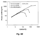
- FIGS. 9A 9 B show the effect of nanostructures on fuel cell output.
- FIG. 9A shows fuel cell voltage plots as a function of output current per mg Pt content in the catalysts.
- Three samples compared are (1) a standard assembled three-layer fuel cell purchased from ElectroChem with 1 mg/cm 2 Pt catalysts, (2) Pt 0.12 Co 0.88 thin film catalyst coated on carbon nanotubes which is directly grown on carbon fiber paper with 200 ⁇ Co catalyst, and (3) Pt 0.12 Co 0.88 thin film catalyst coated on carbon nanotubes which is directly grown on carbon fiber paper with 200 ⁇ Ni catalyst.
- FIG. 9B shows fuel cell power per mg Pt content in the catalysts plots as a function of output current.
- FIG. 10 illustrates nanoparticles (e.g., carbon nanotubes) grown on fibers (e.g., carbon fibers).
- the nanoparticles are coated with a catalytically active substantially continuous thin film or Pt (see inset).
- FIG. 11 shows SEM photographs of three samples: (1) Pt 0.12 Co 0.88 thin film catalyst directly coated on carbon fiber paper, (2) Pt 0.12 Co 0.88 thin film catalyst coated onto carbon nanotubes which were directly grown on carbon fiber paper using 200 ⁇ Co nanoparticles catalyst, and (3) Pt 0.12 Co 0.88 thin film catalyst coated on carbon nanotubes which are directly grown on carbon fiber paper with 200 ⁇ Ni nanoparticles catalyst.
- FIG. 12 illustrates a structure of three-layer electrical conducting materials with optimized porosity and thickness for each layer.
- FIG. 13A panels A through F, show SEM photographs of carbon nanotubes directly grown on carbon fibers of Toray Carbon Paper and thin films on carbon nanotubes.
- Panel A An SEM photograph at 45 ⁇ magnification of a sample of Pt thin film (250 ⁇ ) ion-beam sputtered onto carbon nanotubes which were directly grown on a carbon fiber paper substrate by chemical vapor deposition with Ni as the nanoparticles catalyst. The lighter area on the left corner shows the Pt coating.
- Panel B An SEM photograph at 300 ⁇ magnification of a sample of Pt thin film (250 ⁇ ) ionbeam sputtered on carbon nanotubes which were directly grown on a carbon fiber paper substrate by chemical vapor deposition with Ni as catalyst.
- Panel C An SEM photograph at 3000 ⁇ magnification of a sample of Pt thin film (250 ⁇ ) ion-beam sputtered on to carbon nanotubes which were directly grown on a carbon fiber paper substrate by chemical vapor deposition with Ni as catalyst. It shows uniform carbon nanotube networks on the carbon fibers.
- Panel D An SEM photograph at 20,000 ⁇ magnification of a sample of Pt thin film (250 ⁇ ) ion-beam sputtered on carbon nanotubes which were directly grown on a carbon fiber paper substrate by chemical vapor deposition with Ni as catalyst. It shows uniform carbon nanotube networks on carbon fiber.
- Panel E An SEM photograph at 100,000 ⁇ magnification of a sample of Pt thin film (250 ⁇ ) ion-beam sputtered on carbon nanotubes which were directly grown on a carbon fiber paper substrate by chemical vapor deposition with Ni as catalyst. It shows uniform size Pt coated of carbon nanotubes in order of 100 nm.
- Panel F An SEM photograph at 200,000 ⁇ magnification of a sample of Pt thin film (250 ⁇ ) ion-beam sputtered on carbon nanotubes which were directly grown on a carbon fiber paper substrate by chemical vapor deposition with Ni as catalyst. It shows a substantially continuous Pt thin film coating on individual carbon nanotubes.
- FIGS. 14A and B illustrates an advantage of the fuel catalysts and nanoparticles of this invention.
- the fuel cell catalysts can be incorporated into the porous electrodes (illustrated by embodiment 14 A right) thereby eliminating the separate catalyst layers and microdiffusion layers present in a more traditional configuration (illustrated by embodiment 14 A left).
- An SEM micrograph of the actual structure is shown in FIG. 14B with the carbon paper support being on the bottom and CNT layers being shown on the top and bottom of the polymer membrane.
- An actual MEA fabricated as per this invention ( 14 A right) is shown in an SEM image in FIG. 14B .
- FIGS. 15A and B are electron micrographs showing relatively dispersed and uniform ionomer coating achievable using high pressure contacting of nanotubes with an ionomer solution.
- FIG. 16 is a chart showing improved current density in an electrode ionomer coated at a high pressure.
- the Y-axis represents voltage and the X-axis represents current induced by the corresponding voltage.
- FIG. 17 is a schematic diagram of a system using a high pressure pump to coat nanostructures with an ionomer.
- FIG. 18 shows a schematic diagram of a pressure cell designed to be compressed with a hydraulic press. It consists of a top piston which compresses the fluid and pressurizes the samples held on the sample holder.
- FIG. 19 is a schematic diagram of a system for electrodeposition of metals onto a nanostructure electrode.
- FIG. 20 shows a comparative SEM of carbon nanotubes with platinum electroplated on them (top) and with subsequent nafion coating (bottom).
- FIG. 21 shows a comparison in fuel cell performance between MEA's fabricated using sputtered platinum and electroplated platinum.
- FIG. 22 shows a comparison in fuel cell performance between a commercial MEA fuel cell with high platinum loading (0.5 mg Pt/cm 2 ) and a nanotube based MEA (0.05 mg Pt/cm 2 ) with low platinum loading.
- This invention pertains to the development of improved catalysts and integrated gas-diffusion/electrode/catalysts (IGEC) for use in fuel cells. Also provided are fuel cells, fuel cell electrode combinations that utilize the improved catalysts.
- IGEC integrated gas-diffusion/electrode/catalysts
- the catalysts of this invention comprise nanoparticles coated with a substantially continuous thin film comprising a catalytically active metal (e.g. platinum, platinum alloys, etc.).
- a catalytically active metal e.g. platinum, platinum alloys, etc.
- the catalytic efficiency of the thin film is increased by increasing the effective reactive surface area by depositing the thin film comprising a catalytically active metal or alloy onto nanoparticles.
- the nanoparticles can be partially coated with the substantially continuous thin film or completely covered with the substantially continuous thin film.
- the thin film ranges in thickness from about 1 nm to about 500 nm, preferably from about 2 nm to about 300 nm, more preferably from about 5 nm to about 100 nm and most preferably from about 10 nm to about 50 nm.
- the coated areas catalytic material thickness is substantially uniform, e.g., with the thickness varying less than 50%, less than 25%, less than 10%, or less than 5%.
- the nanoparticles can include any of a wide range of nanoparticle types. Typical nanoparticles have at least one dimension smaller than about 500 nm, more preferably at least two dimensions or three dimensions each less than about 500 nm. In certain embodiments, the nanoparticles are characterized by at least one dimension smaller than about 100 nm, or 50 nm, or about 10 nm.
- Suitable nanoparticles include, but are not limited to various fullerenes, carbon nanotubes, carbon nanohorns, carbon (and other) nanofibers, nano sphere/powder, quantum dots, metal encapsulated fullerenes, and the like.
- the nanoparticles incorporate carbon.
- carbon-based nanoparticles including, but not limited to carbon nanotubes, carbon nanohorns, carbon nanofibers, nano sphere/powder, and the like are particularly well suited for use in the catalysts of this invention.
- nanoparticles can take any of a number of possible morphologies and still be suitable for use in the present invention.
- this invention contemplates using nanotubes of the following kinds: single-walled, double-walled, multi-walled, with zig-zag chirality, or a mixture of chiralities, twisted, straight, bent, kinked, curled, flattened, and/or round; ropes of nanotubes, twisted nanotubes, braided nanotubes; small bundles of nanotubes (e.g., in certain embodiments, with a number of tubes less than about ten), medium bundles of nanotubes (e.g., in certain embodiments, with a number of tubes in the hundreds), large bundles of nanotubes (e.g.
- nanostructures can assume heterogeneous forms.
- heterogeneous forms include, but are not limited to structures, where one part of the structure has a certain chemical composition, while another part of the structure has a different chemical composition.
- An example is a multi walled nanotube, where the chemical composition of the different walls can be different from each other.
- Heterogeneous forms also include different forms of nanostructured material, where more than one of the above listed forms are joined into a larger irregular structure.
- any of the above materials can have cracks, dislocations, branches or other impurities and/or imperfections.
- the nanoparticles are partially or completely covered with a substantially continuous thin film comprising a catalytically active metal or alloy.
- the catalytically active metal or alloy comprises platinum (Pt).
- Suitable alloys include, but are not limited to binary alloys such as Pt—Cr, Pt—V, Pt—Ta, Pt—Cu, Pt—Ru, Pt—Y, etc., and/or ternary alloys including but not limited to Pt—Ru—Os, Pt—Ni—Co, Pt—Cr—C, Pt—Cr—Ce, Pt—Co—Cr, Pt—Fe—Co, Pt—Ru—Ni, Pt—Ga—Cr—Co, Pt—Ga—Cr—Ni, Pt—Co—Cr, etc., and/or quaternary alloys including, but not limited to Pt—Ni—Co—Mn, Pt—Fe—Co—Cu, etc.
- Platinum content per unit area is one of the most important cost criteria for practical PEM fuel cell applications.
- binary, ternary and quaternary composition of Pt alloys that contains Co, Ni, Mo and V are optimized e.g. as illustrated in FIG. 2 . Vanadium was found to significantly enhance catalyst oxidation resistance as shown in FIG. 3 .
- the thin film comprises an alloy comprising platinum (Pt) and vanadium (V) and, optionally, one or more additional metals (e.g. Co, Ni, Mo, Ta, W, Zr, etc.).
- a PtNiCoV alloy is a preferred Pt alloy catalyst system for both anode and cathode of PEM fuel cells as shown in FIG. 4 .
- Platinum (Pt) concentration was also optimized in a platinum alloy system.
- FIGS. 3A and 3B show that the output current of fuel cell increase quickly as Pt concentrations increase, but the output current saturates at about 12% Pt in both Pt—V and Pt—Co alloy systems. Therefore, in certain embodiments, a preferred platinum concentration in a platinum catalyst alloy is 12% or less for both cathodes and/or anodes of PEM fuel cells.
- the thin film comprises an alloy having the formula:
- the catalyst layer thickness was also optimized in certain embodiments so as to minimize platinum content.
- FIG. 5 shows that the current output saturates at a thin film thickness about 100 ⁇ for a catalyst Pt 0.12 Co 0.88 alloy. Consequently, in certain preferred embodiments, the thickness of thin film Pt alloy catalysts is 200 ⁇ or less in cathodes and/or anodes of PEM fuel cells.
- the thin film is not substantially continuous, but rather non-continuous, e.g., non-contiguous or “variegated” to form a plurality of islands/islets on the underlying nanoparticles.
- the film thickness of the islets ranges from about 5 to about 100 angstroms, while the area ranges from about 1 to about 10 4 nm 2 .
- the thin films can be applied to the nanoparticles by any of a number of convenient methods.
- the thin films can be applied by simple chemical methods.
- the thin film can be applied to the nanoparticles by direct spraying or by exposing the nanoparticles to a solvent containing the thin film materials and allowing the solvent to evaporate away.
- the thin film can be electro-deposited (e.g. electroplated) onto the nanoparticles.
- the thin film is applied to the nanoparticles by conventional semiconductor processing methods, e.g.
- the catalytic efficacy of the thin film is increased by providing the thin film as a substantially continuous thin film on nanoparticles (e.g., carbon nanotubes).
- nanoparticles e.g., carbon nanotubes.
- FIG. 6A shows that the carbon nanotube supported Pt 0.12 Co 0.88 catalysts can increase the output current per mg Pt by one order of magnitude under the same operation voltage.
- FIG. 6B shows that the carbon nanotube supported Pt 0.12 Co 0.88 catalysts can increase the output power per mg Pt by one order of magnitude within the entire current operation range.
- FIGS. 7A and 7B again confirms that 12% Pt is sufficient for carbon nanotube supported Pt alloy catalysts.
- FIGS. 8A and 8B indicate that the density and size of carbon nanotubes, which are controlled by catalyst thickness, growth time and catalyst material effect catalyst performance.
- preferred carbon nanotubes are few to 100 nanometers with optimized density.
- FIG. 13 shows structures of thin-film catalyst coated on carbon nanotubes which are directly grown on carbon fibers in the top layer of Toray carbon paper at magnifications from 45 to 200,000 times by scanning electron microscope. The carbon nanotubes were uniformly grown on individual fibers as shown in FIG. 13 (panel B). The carbon nanotube layer is about 10 ⁇ m thick with uniform networks as shown in FIG. 13 , panels C, D, and E.
- FIG. 13 , panel F shows substantially continuous Pt thin films (catalysts) on the carbon nanotubes.
- the nanoparticles used in the catalysts of this invention can be provided in various forms, e.g. in solution, as a dried powder, and/or grown on porous substrates.
- the nanoparticles are grown and retained on a porous substrate.
- this porous substrate can itself act as an electrode.
- this invention pertains to the optimization of catalysts for the growing of nanoparticles, more preferably for the growing of carbon nanotubes.
- nanoparticles e.g. carbon nanotubes
- supports e.g. carbon fibers
- a substantially continuous thin film e.g., a catalytically active thin film
- the nanoparticle catalyst (“seed”) often remain exposed on the surface of the nanoparticle (e.g. at the end of a carbon nanotube). Consequently, when a thin film is applied to the nanoparticles comprising the catalyst (seed), the catalyst (seed) particles mix with material forming the thin film and can alter the catalytic activity of the thin film. Thus, it is desirable to grow the nanoparticles using nanoparticles catalyst materials that are compatible with growth of the nanoparticles and that either enhance, or do not substantially adversely affect the catalytic activity of the applied thin film.
- nanoparticles catalysts are good for both nanoparticles growth and fuel cell operation.
- iron is a good for growing carbon nanotubes, but can interfere with the catalytic activity of the applied thin film.
- Some elements or their alloys are good for both nanoparticles (e.g., carbon nanotube) growth and fuel cell operation.
- These “optimal” seed materials include, but are not limited to Co, Ni, V, and Mo.
- alloys listed below are particularly well suited for carbon nanotube growth and also fuel cell operation. They can enhance the fuel cell catalytic properties greatly in many cases.
- the catalysts for growing the nanoparticles include, one or more of the following: Co 8.8 Mo 1.2 , Co 2.2 Ni 5.6 Mo 2.2 , Co 5.7 Ni 2.1 V 1.1 Cr 1.1 , Ni 8.0 Mo 1.0 Al 1.0 and Co 6.4 Ni 2.4 Al 1.2 .
- the fuel cell catalysts of this invention are fabricated into electrode/membrane combinations.
- One typical electrode/membrane combination includes at least a first conductive electrode comprising a first fuel cell catalyst (nanoparticles partially or completely coated with a substantially continuous catalytic thin film); at least a second conductive electrode comprising a second fuel cell catalyst; and a proton exchange membrane separating the first conductive electrode and the second conductive electrode.
- the catalyst in a more traditional configuration (see, e.g., ′′ii) in FIG. 14A ), the catalyst (nanoparticles coated with a thin film) forms a separate layer on the electrode or on a polymer membrane.
- a microdiffusion layer can optionally be present.
- Such a configuration thus comprises seven discrete layers (two electrodes, two catalyst layers, two microdiffusion layers, and a PEM). It is a surprising discovery and advantage of the present invention however, that the nanoparticles can interleave with the fibers comprising a gas-diffusable electrode (e.g. a carbon fiber sheet) and thus the fuel cell catalyst (thin-film coated nanoparticles) can be fabricated so that they are integral with the electrode.
- a gas-diffusable electrode e.g. a carbon fiber sheet
- this invention contemplates an integrated gas-diffusion/electrode/catalyst (IGEC) and membrane combination comprising only three layers; e.g., two IGEC layers separated by a proton exchange membrane (see, e.g., “ii)” in FIG. 14A ).
- IGEC gas-diffusion/electrode/catalyst
- Such an integrated microdiffusion layer and catalyst/carbon layer can be readily fabricated.
- carbon nanotubes CNT can be directly grown on carbon fibers on the surface layer (1-5 fiber diameter) carbon fiber sheet (see, e.g., FIG. 10 ).
- the bare carbon fiber diameter is about 10 ⁇ m (see, e.g., FIG. 11 , panel 1 ) and the CNT covered carbon diameter is about 50 ⁇ m (see, e.g., FIG. 13B ).
- the large pores of the gas diffusion electrode are thus converted into small pores and the CNT covered top carbon fiber layer can act as a microdiffusion layer enhancing the dispersion of gas (e.g. hydrogen) to the catalyst.
- the platinum or alloy thin film coating on top of the carbon nanotubes acts as an efficient catalyst structure with large surface area.
- nanoparticles e.g., CNTs, CNHs, or other nanopowders
- carbon fiber sheet or other gas diffusion electrodes
- An intermediate microdiffusion layer can, optionally, be used between the nanoparticle/catalyst layer and carbon fiber sheet (gas diffusion electrode), e.g. as shown in FIG. 12 .
- fibers or whiskers made of carbon, and/or other electrical conducting materials are grown up on porous electrical conducting substrates. They can be used as a support for the catalytic thin film.
- carbon nanotubes are grown directly on a commercial carbon fiber paper; then a thin layer of catalyst, e.g., Pt, Ni, Co, Fe and their alloys, is deposited by chemical vapor deposition on the carbon nanotubes as shown schematically in FIG. 1 .
- catalyst e.g., Pt, Ni, Co, Fe and their alloys
- Carbon nanotubes or other similar electrical conducting nanostructured materials can also be sprayed or brushed on carbon fiber paper (gas diffusion) electrodes.
- Platinum alloy thin film catalysts can then be deposited on these carbon nanotube layers which directly contact a proton exchange membrane (PEM).
- PEM proton exchange membrane
- carbon nanotubes or other similar electrical conducting nanostructured materials can also be prepared as a thin sheet with an optimized porosity and preferred thickness e.g., of a few nanometers to tens of micrometers.
- the thin sheet is then placed or pressed on carbon fiber paper.
- the thin film catalysts can then be deposited on the carbon nanotube sheet which directly contacts the proton exchange membrane.
- the carbon nanoparticles are coated with the thin film catalysts first.
- electroplating can be used to fabricate such catalyst-coated carbon nanotubes or other similar electrical conducting nanostructured materials.
- These catalyst-coated electrical conducting nanostructured materials can then be sprayed, brushed or painted on the carbon paper electrodes or on fuel cell membrane layer.
- these catalyst coated electrical conducting nanostructured materials can also be prepared as a thin sheet with an optimized porosity and preferred thickness of few to tens of micrometers. Such sheet will then placed or pressed on carbon fiber paper.
- the top layer can be made of catalytic thin film catalyst coated carbon nanotubes having diameters ranging from a few nanometers to 100 nanometers with, e.g., high aspect ratios to provide as large surface as possible for catalysis and a uniform micro or nano-porous distributed layer.
- the thickness of this layer can be precisely controlled (e.g., to a few tens of nanotube layers since these are expensive materials).
- the intermediate layer is made of carbon fibers or powders with a fiber or a carbon sphere diameter of sub-micrometer to a few micrometers, and a layer thickness about ten to a few tens of micrometers.
- the commercial Toray carbon fiber paper with a fiber diameter ranging from a few to a few tens (e.g., 3 to 100) of micrometers, and a paper thickness of few hundreds of micrometers, is well suited for this application.
- Such structures can have an average pore size and pore density gradually changing from bottom layer to the top layer.
- Suitable proton exchange membrane materials include, but are not limited to Nafion brand ionomer, silicon oxide Nafion composite (see, e.g., Adjemian et al. (2002) J. Electrochem. Soc., 149(3): A256-A261), polyphosphazenes (a hybrid inorganic/organic polymer with a —P ⁇ N— backbone) for high temperature PEMFCs (see, e.g., Fedkin et al. (2002) Materials Letters, 52: 192-196; Chalkova et al.
- the porous gas diffusion layer can have a hydrophobic surface.
- hydrophobicity and removal of water can be enhanced by coating the substrate with a hydrophobic polymer, such as Teflon brand polytetrafluoroethylenes, or aluminum oxide treated, e.g., with fluoroalkylsilanes.
- a hydrophobic polymer such as Teflon brand polytetrafluoroethylenes, or aluminum oxide treated, e.g., with fluoroalkylsilanes.
- the following strategy can be useful to selectively coat a substrate that is initially relatively hydrophilic compared to the electrode layer.
- the hydrophobic layer can be coated onto the electrode, then the surface can be etched, either by plasma or by liquid, in order to allow for the deposition of metal directly on the carbon nanostructures.
- This method provides for an intimate electrical contact between the platinum/alloy and the electrode without interference from the insulating hydrophobic layer.
- AlOx aluminum oxide
- only the carbon paper support would be coated with AlOx, the surface etched for nickel/alloy deposition, the nanotubes grown by CVD, platinum/alloy deposited, and then finally the entire electrode treated with fluoroalkylsilane.
- Electroplating catalyst metals onto nanostructures of electrodes in the invention is an option that has certain advantages over methods in many cases.
- catalyst metals such as platinum
- these techniques lead to inefficient use of the catalyst, reduced porosity and sub-optimal catalyst surface area.
- electrodeposition procedures can be practiced on some nanostructures to apply catalytic metals in a uniform, well dispersed and controlled fashion.
- carbon nanotube (CNT) electrodes e.g., having a porous conductive substrate bearing a layer of carbon nanotubes
- a thin layer of catalyst can be controllably deposited on the nanostructures by electrolysis.
- the electrode nanotube surface can be sometimes hydrophobic, as initially prepared.
- the electrodes can be made hydrophilic, e.g., by heated up at 350° C. in air.
- wetting agents such as surfactants, ampholytes, and water soluble organic compounds
- nanotubes can be better wetted and more affectively coated with catalyst using a plating solution containing isopropyl alcohol.
- a thin electrode seed layer can be applied to the nanotubes before the electroplating step, e.g., to direct and accelerate later electrodeposition of metals onto the nanotubes.
- a 25 ⁇ coat of platinum can be sputtered onto the electrode as a seed layer for latter electroplating.
- the seed coat can be other metals such as, e.g., Co, Ni, V, Cr, Pt, Ru, Mo, W, Ta, Zr, and the like.
- the electroplating solution typically contains soluble salts of the desired metals, e.g., along with additives for control of pH, wetting, plating morphology, and such.
- a preferred electroplating solution contains H 2 PtCl 6 , HCl, and lead acetate (to improve deposition surface morphology).
- the plating solution can contain combinations of metals, resulting in uniform alloy coatings or coatings with alloy compositions changing through the thickness of the coat. In a typical embodiment, the plating solution contains about 10 g/L platinum and about 60 g/L HCl.
- FIG. 19 A typical system for electroplating metals onto CNT electrodes is shown in FIG. 19 .
- CNT electrode 216 is mounted onto a cathode with the nanotube layer facing out and the conductive substrate layer in electrical contact with the cathode.
- Uniform current flow through the CNT electrode can be provided by placing a layer of copper tape 215 between the CNT electrode and graphite block 212 .
- the graphite block can be pivotably mounted on a ball joint 211 so that the CNT electrode can be placed precisely flat onto the top surface (in the same plane) of plating solution 217 held in container 214 .
- Power supply 220 can be in electrical contact with the cathode through cathode connection 213 and with anode 218 (immersed in the plating solution) through anode connection 219 .
- direct current from the power supply provides electrons at the cathode, attracting positively charged metal ions to the CNT electrode surface where they are converted to metallic form by receipt of electrons. Counter ions of the metals migrate to the anode where they give up electrons, e.g., to form elemental gasses.
- the power source provides a pulsed net DC current. In a typical plating operation of Pt onto a CNT electrode, the power source provides a 40 Hz current pulse with a 20% duty cycle. Plating can continue, e.g., with a current density of about 200 mA/cm 2 for about 15 sec to complete the plating (electrodeposition) of about 0.5 mg/cm 2 platinum loading onto the nanotubes. After plating, the sample is washed thoroughly to remove the residual plating solution.
- the conductivity of the plating solution can affect the depth of metal electrodeposition within a nanostructure layer. Without being bound to a particular theory, a lower current flow experienced in low conductivity solutions can cause available metal ions to be scavenged at the outer tips of the nanostructures without significant plating at the nanostructure surfaces closer to the electrode substrate. A higher current flow can result in an abundant metal ion flux that penetrates deeper into the carbon nanotube layer.
- the conductivity of the plating solution can be adjusted, e.g., by controlling the solution pH, the amount of metal salts, and/or the concentration of other electrolytes in the solution.
- the depth of electrodeposition can be affected by controlling the amount of time electrolyte has to migrate into the nanostructure layer.
- a CNT electrode can be saturated with a low conductivity solution without significant concentrations of metal ions.
- the CNT electrode can be placed in contact with the plating solution to allow diffusion of the catalyst metal ions into CNT layer.
- the metal ions penetrate different distances into the CNT layer.
- the amount of catalyst metal plated through the depth of the CNT layer can depend on how long the ions were allowed to diffuse into the layer.
- diffusion speed of typical ions in aqueous solution was in the order of 0.1 ⁇ m per second, so a 5 ⁇ m thick catalyst layer could be formed, e.g., after a diffusion waiting time of about 50 sec.
- the electrode nanostructure have some surface ionic character to facilitate the conduction of electrons and/or to facilitate transit of protons in fuel cell applications.
- the nanotubes in the case of carbon nanotubes grown on a substrate layer, it can be difficult, to coat the nanotubes with conductive materials using standard methods. Methods, such as dipping, spraying and brushing coating materials typically fail to provide a uniform coat, a thick coat, or a coat that penetrates adequately into the CNT layer.
- FIG. 15A is a scanning electron microscope image showing how sprayed perfluorocarbonsulfonic acid ionomer (Nafion®) forms an occlusive top layer.
- Nafion® perfluorocarbonsulfonic acid ionomer
- hydrostatic pressure can greatly improve coating of nanostructures with ionic polymers.
- Contact and coating of nanostructures with polyions (ionomers), such as a Nafion solution can be greatly improved by contacting at high pressures ranging, e.g., from about 100 psi to about 10000 psi, or about 5000 psi.
- Contact and coating of nanostructures under high hydrostatic pressures can give a more uniform and complete coating, as shown in FIG. 15B .
- the improved coating can significantly improve the capacity and current density for electrode layers coated with using the high hydrostatic pressure technique, as shown in FIG. 16 .
- the nanostructures can be contacted with the ionomer solution under pressure in a pressure vessel.
- the nanostructures can be premixed with the ionomer solution before introduction to the vessel or they can be mixed in the vessel.
- the ionomer solution is combined with the nanostructures by flowing the solution through a bed of the structures.
- the vessel can be a chromatography column and the solution can be pumped through the nanostructures using a high pressure liquid chromatography (HPLC) pump.
- Nanostructures can be contacted with the solutions at high pressures in batch or continuous processing modes. For example, as shown in FIG.
- a system for coating of nanostructures can include a high pressure pump to introduce an ionomer solution to at high pressure to a pressure vessel containing the nanostructures.
- the system can include a drain and vacuum pump to recover unused solution.
- the pressure can be generated by any appropriate technique known in the art.
- the pressure can be from, e.g., pressurized gasses, explosive chemical reactions, piston pumps, mechanical compression of chambers, and/or the like.
- high pressure can be generated manually for batch processing of the coating step.
- the nanostructures, free or bound to a substrate can be placed in the pressure vessel chamber along with the ionomer solution.
- the pressure vessel cap can be threaded onto the top of the chamber to form a seal. Additional turning of the cap can result in very high chamber internal hydrostatic pressures that increase the efficiency of nanostructure/solution contact and coating processes.
- pretreatment of the nanostructure in the ionomer solution can further enhance the efficiency of coating.
- the combined nanostructure and polyion solution can be pretreated by exposure to a vacuum pressure (environmental pressure less than one atmosphere).
- Vacuum pretreatment can include exposure of the nanostructures in the solution to a pressure less than 300 torr, less than 100 torr, less than 5 torr or less than 1 torr.
- the vacuum treatment expands gasses trapped between the nanostructures, allowing them to escape; the solution replacing the gasses on return to ambient pressure.
- Pretreatment can include sonication of the nanostructure/solution combination. Again, it is believed the sonication aids in removal of gasses on the macroscopic and microscopic scale, so the solution can gain better access to nanostructure surfaces.
- repeated high pressure processing cycles can be used to control or increase coating thickness.
- the nanostructures can be taken out of the pressure vessel and dried, e.g., in ambient air for 15 minutes. Then, the nanostructures can be combined with additional ionomer solution before exposure to high pressure followed by drying. A thin film of solidified polyion can be formed on the nanostructure surface, after each drying, that accumulates with each processing cycle.
- the cycles of combination, pressurization and drying can be repeated until the desired coating thickness and/or percent surface coverage is obtained. We have found that washing the nanostructures with ethanol and removal by application of vacuum can help avoid too much polyion accumulation in undesired places, such as gas diffusion channels.
- a thin film of an ionomer such as Nafion
- a thin film of an ionomer can be applied by brushing or spraying onto the nanostructure before drying.
- the nanostructure can then be put into a solvent, such as isopropanol before application of hydrostatic pressure in a pressure vessel.
- the ionomer can migrate to coat nanostructures beneath to zone of application. This technique has the benefit of providing control over the loading and location of polyion coating.
- Plasma etching can be used in various processes, described herein, for preparation of electrodes comprising porous substrates bearing nanostructures.
- Plasma etching can controllably treat a substrate surface or nanostructure surface, resulting in, e.g., removal of a layer from the surface and/or a change in certain qualities of the surface.
- Plasma etching can be used in conjunction with other methods to facilitate processing steps and/or to control properties of electrode final products.
- Plasma etching typically takes place with an electrode on a stage in a vacuum chamber.
- the chamber has an ion or electron (plasma) source that can inject a stream of charged particles into the chamber.
- the electrode is typically a planar or membranous layered structure and usually rests on the stage with the side to be etched facing the plasma source.
- the interaction of the electrode surface with the plasma can result in material being removed from the surface and/or changes in the surface chemistry.
- the extent of material removal or other surface changes can be influenced to the intensity of the plasma and/or the time of surface exposure to the plasma.
- the intensity of the plasma can be adjusted in many ways, known in the art, e.g., by adjusting the voltage of the plasma source, adjusting the flow rate of gasses fed into the plasma source, adjusting the pressure within the chamber, adjusting the focus of a plasma beam, and/or the like.
- the voltage of the plasma source can be adjusted in a range from about 100 V to about 3000 V, from 500 V to about 2000 V, or about 1000V.
- the chamber pressure can be adjusted, e.g., in the range from less than about 0.1 torr to about 500 torr, from about 1 torr to about 100 torr, or about 10 torr.
- plasma etching can be used to increase the hydrophilicity of a nanostructure layer.
- the charged particles can interact with nanostructure surface in chemistries that produce polar or charged chemical structures.
- Such chemical structures can have an affinity for polar solvents, such as aqueous solutions, thus improving chemical and/or physical interactions between the nanostructures and certain solutions.
- an electrode comprising a layer of carbon nanotubes bound to a porous substrate layer of carbon fibers is etched by exposure to a plasma to improve subsequent coating with an ionomer.
- the nanotubes are substantially hydrophobic and not very receptive to processing by aqueous chemistries.
- the electrode can be placed in a vacuum chamber on a stage with the nanotube layer facing the chamber cavity. The chamber can be partially evacuated and an argon ion plasma injected from a plasma source. With time and intensity of plasma exposure, the nanotubes can become less hydrophobic.
- nanotubes thus treated can be contacted with an aqueous emulsion or solution of an ionomer to receive an ionomer coating with improved quantity, dispersion and/or uniformity.
- This technique can be used in conjunction with the high pressure coating techniques described above.
- a layer of carbon nanotubes bound to a porous substrate layer of carbon fibers is etched with a plasma to improve wettability of the nanotube layer in preparation for subsequent processing by an electrodeposition method.
- a carbon nanotube layer of an electrode can be exposed to a plasma that converts the relatively hydrophobic CNT surface into a relatively hydrophilic surface.
- electroplating solutions will realize more thorough contact with the nanotubes. The extent of conversion can influence the depth and quantity of the subsequent electrodeposition.
- plasma etching of electrode layers can be used to remove undesired materials from surfaces of the layers.
- plasma etching can be used to remove undesired substrate coating material or wax masking material from nanostructures.
- the coating material i.e. Teflon or treated Aluminum Oxide
- plasma etching can be used to remove the coating material from the contacted nanotubes. The etching can remove the coating material (and possibly increase the nanotube hydrophilicity) without removing the desired coating from the substrate layer.
- the nanotubes can be made accessible for subsequent processing, such as, e.g., contacting and ionomer coating of the nanotubes, electrodeposition of metals onto the nanotubes, etc.
- the depth of the subsequent processing can be influenced by the depth of the etching, as described above.
- the membrane electrode combinations (membrane electrode assemblies) of this invention can be stacked (assembled) to increase the voltage and hence, the current and/or power output.
- Fuel cells can be configured to deliver desired levels of power for the particular application(s) for which the fuel cell is intended.
- adjacent single cells are typically electrically connected by means of bipolar plates (BPP) positioned between the surfaces of the electrodes opposite to those contacted with the electrolyte membrane.
- BPPs bipolar plates
- BPPs or separators are often made of metals, particulate carbon and graphite materials, impregnated graphite, or molding compounds consisting of graphite and a polymer binder (see, e.g., U.S. Pat. No. 4,214,969).
- Flow channels or grooves on the surfaces of the BPP provide access for the fuel to the adjacent anode and for the oxidant to the adjacent cathode and removal of the reaction products and the unreacted remnants of fuel and oxidant. These flow channels reduce the useful surface of the BPP, as the electrical contact area is limited to the part of the surface between the channels.
- the electrodes typically comprise a porous structure referred to as gas diffusion layer (GDL).
- GDL gas diffusion layer
- the GDL(s) provide an efficient entry passage for both fuel and oxidant, respectively, to the catalyst layer as well as an exit for the reaction products away from the catalyst layer into the flow channel of the adjacent BPP.
- the GDL surface area exposed to the channels is typically as large as possible. It is preferred, therefore, that a large portion of the BPP surface is consumed by the flow channels with only a small portion remaining for the electrical contact. Reduction of the electrical contact area is limited, however, by the high contact resistance between BPP and GDL.
- the contact area between these two is desirably sufficiently large to avoid local overheating at high current densities which would finally lead to destruction of the assembly.
- Fuel cells fabricated according to this invention are can configured as a suitable energy source for virtually any application. Such applications include, but are not limited to electric vehicles, computers, cell phones, and other electronic devices, home electrical power generation systems, and the like. Fuel cells are particularly desirable since they have been shown to exhibit high energy conversion efficiency, high power density and negligible pollution.
- one convenient source of hydrogen gas can be from steam reformation of methanol, since methanol can be stored more easily in a vehicle than hydrogen.
- Pt alloy thin film catalysts were processed through multiplayer depositions and post diffusion annealing.
- the thickness ratio calculated from atomic weight of the selected elements will be used to control a desired composition.
- the thickness gradient profiles were generated during the deposition process.
- the ion beam sputtering depositions were carried out under a typical condition of 10 4 torr and room temperature with pure metal targets. Typical total thickness of multilayers was about 100 ⁇ .
- Post annealing for inter-diffusion were carried out at 700° C. for 12 hours under 10 ⁇ 8 torr vacuum.
- the commercial carbon fiber papers were used as substrates for most of the composition studies.
- the carbon nanotubes deposited on the carbon fiber papers were used for enhancing the catalyst surface area and providing a micro gas-diffusion structure.
- the growth procedures for carbon nanotubes on carbon fiber of Toray carbon paper were:
- Nanotubes were ground in an agate ball miller with ethanol. The suspension produced was smeared or sprayed on the Toray carbon paper. Pt was Ion-Beam deposited on the top surface of the smeared nanotubes. The measured catalytic effectiveness reached the level of that on grown nanotubes.
- a Toray® carbon paper substrate was sputtered with 400 ⁇ of nickel.
- the substrate was then put in a furnace and CNT grown onto it by a CVD method. It is preferable that the CNT layer thickness is around 30 ⁇ m.
- the substrate can be treated with heat and/or chemicals to modify the hydrophobicity of the CNT layer.
- Platinum was added to the CNT layer by sputtering and/or electrodeposition.
- the sample was put under high hydrostatic pressure in a Nafion® solution. The pressure is preferably around 5000 psi.
- the sample was taken out and the substrate side without CNT was washed with ethanol.
- the sample was then air dried for 15 minutes at ambient temperature.
- the sample was again put into the Nafion solution under high pressure.
- the cycle was repeated 5 times.
- the finished electrode was then baked on a hotplate to remove residual solvent and hot pressed to produce an anode electrode with a Nafion® film on one side.
- a Toray® carbon paper substrate was sputtered with 400 ⁇ of nickel. The substrate was then put into a chamber to grow CNT by CVD method. It is preferable that the CNT layer thickness is around 30 ⁇ m.
- the substrate can be treated with heat and/or chemicals to modify the hydrophobicity of the CNT substrate. Platinum was added to the CNT layer by sputtering and/or electrodeposition. Then a thin film of Nafion® was applied onto the CNT layer by spraying and drying. The Nafion® coated sample was put into an iso-propanol solvent and hydrostatic pressures applied for 5 minutes. The sample was then taken out of the pressure vessel and dried. The finished electrode was baked on a hotplate to remove solvent and hot pressed to produce an anode electrode with a Nafion® film with on one side.
- hydrophobic gas diffusion layer and micro-diffusion layer on an electrode in order to get better water management in a PEM fuel cell.
- hydrophilic electrode surface e.g., to facilitate processing steps, such as ionomer coating or Pt electroplating.
- the following embodiment describes how an electroplated on one side following application of a hydrophobic coating.
- the procedure includes the following steps:
- the total Teflon loading is preferably to be 20% by weight.
- the depth of electroplating down into CNT surfaces can be controlled by, e.g., the electroplating solution conductivity, diffusion time of plating solution into the CNT layer, etc., as described herein.
- ionomer coatings can be applied to the CNT layer after the plasma etching treatment.
- perfluoroalkylsilane treated Aluminum Oxide could be used in place of Teflon in the example above.
Abstract
Description
-
- PtxVyCozNiw, where x is greater than 0.06 and less than 1; y, z, and w are independently greater than zero and less than 1; and x+y+z+w=1.
-
- 1. Co1-xMox where 0≦x≦0.3;
- 2. Co1-x-yNixMoy where 0.1≦x≦0.7 and 0≦y≦0.3;
- 3. Co1-x-y-zNixVyCrz where 0≦x≦0.7, 0≦y≦0.2, and 0≦z≦0.2;
- 4. Ni1-x-yMoxAly where 0≦x≦0.2, 0≦y≦0.2;
- 5. Co1-x-yNixAly where 0≦x≦0.7, and 0≦y≦0.2; and
- 6. FexNiyCo1-x-y where 0≦x≦1 and 0≦y≦1.
-
- (1) Depositing 200 Å thick Ni on carbon fiber paper as catalysts;
- (2) Putting carbon fiber paper into a tube-furnace (6′ long and 2″ in diameter) which connected with Ar, H2 and C2H4 gas lines;
- (3) Flowing Ar at 100 ml/min to push air away for 30 minutes;
- (4) Flowing a mixture of Ar (50 ml/min) and H2 (10 ml/min) into tube furnace and increasing the temperature to 700° C. at 20° C./min;
- (5) At 700° C., changing the mixture of gas flow to Ar (15 ml/min), H2 (15 ml/min) and C2H4(50 ml/min) in tube for 10 minutes; and
- (6) Cooling down the temperature to 20° C. at 20° C./min.
Claims (27)
PtxVyCozNiw
Priority Applications (3)
| Application Number | Priority Date | Filing Date | Title |
|---|---|---|---|
| US11/303,476 US8211593B2 (en) | 2003-09-08 | 2005-12-15 | Low platinum fuel cells, catalysts, and method for preparing the same |
| PCT/US2006/047947 WO2007075437A2 (en) | 2005-12-15 | 2006-12-15 | Low platinum fuel cells, catalysts, and method for preparing the same |
| US13/483,783 US20120238440A1 (en) | 2004-03-02 | 2012-05-30 | Low Platinum Fuel Cells, Catalysts, and Method for Preparing the Same |
Applications Claiming Priority (5)
| Application Number | Priority Date | Filing Date | Title |
|---|---|---|---|
| US50115803P | 2003-09-08 | 2003-09-08 | |
| US54971204P | 2004-03-02 | 2004-03-02 | |
| US10/823,088 US7351444B2 (en) | 2003-09-08 | 2004-04-12 | Low platinum fuel cell catalysts and method for preparing the same |
| US10/898,669 US20050112450A1 (en) | 2003-09-08 | 2004-07-23 | Low platinum fuel cell catalysts and method for preparing the same |
| US11/303,476 US8211593B2 (en) | 2003-09-08 | 2005-12-15 | Low platinum fuel cells, catalysts, and method for preparing the same |
Related Parent Applications (1)
| Application Number | Title | Priority Date | Filing Date |
|---|---|---|---|
| US10/898,669 Continuation-In-Part US20050112450A1 (en) | 2003-09-08 | 2004-07-23 | Low platinum fuel cell catalysts and method for preparing the same |
Related Child Applications (1)
| Application Number | Title | Priority Date | Filing Date |
|---|---|---|---|
| US13/483,783 Division US20120238440A1 (en) | 2004-03-02 | 2012-05-30 | Low Platinum Fuel Cells, Catalysts, and Method for Preparing the Same |
Publications (2)
| Publication Number | Publication Date |
|---|---|
| US20060172179A1 US20060172179A1 (en) | 2006-08-03 |
| US8211593B2 true US8211593B2 (en) | 2012-07-03 |
Family
ID=38218465
Family Applications (2)
| Application Number | Title | Priority Date | Filing Date |
|---|---|---|---|
| US11/303,476 Expired - Fee Related US8211593B2 (en) | 2003-09-08 | 2005-12-15 | Low platinum fuel cells, catalysts, and method for preparing the same |
| US13/483,783 Abandoned US20120238440A1 (en) | 2004-03-02 | 2012-05-30 | Low Platinum Fuel Cells, Catalysts, and Method for Preparing the Same |
Family Applications After (1)
| Application Number | Title | Priority Date | Filing Date |
|---|---|---|---|
| US13/483,783 Abandoned US20120238440A1 (en) | 2004-03-02 | 2012-05-30 | Low Platinum Fuel Cells, Catalysts, and Method for Preparing the Same |
Country Status (2)
| Country | Link |
|---|---|
| US (2) | US8211593B2 (en) |
| WO (1) | WO2007075437A2 (en) |
Cited By (3)
| Publication number | Priority date | Publication date | Assignee | Title |
|---|---|---|---|---|
| US20110003683A1 (en) * | 2009-07-01 | 2011-01-06 | California Institute Of Technology | Nanostructured platinum alloys for use as catalyst materials |
| US10519555B2 (en) * | 2014-08-11 | 2019-12-31 | Newsouth Innovation Pty Limited | Catalytic assembly |
| US20210005902A1 (en) * | 2020-04-23 | 2021-01-07 | Thu Ha Thi Vu | Method of preparing catalyst containing platinum dispersed on graphene quantum dot containing carrier for direct alcohol fuel cell and catalyst obtained by this method |
Families Citing this family (74)
| Publication number | Priority date | Publication date | Assignee | Title |
|---|---|---|---|---|
| US9346673B2 (en) * | 2004-06-23 | 2016-05-24 | Samsung Sdi Co., Ltd. | Electrode for fuel cell, membrane-electrode assembly for fuel cell comprising the same, fuel cell system comprising the same, and method for preparing the electrode |
| KR100578981B1 (en) * | 2004-09-08 | 2006-05-12 | 삼성에스디아이 주식회사 | Electrode for fuel cell and the fuel cell system comprising the same |
| GB0420245D0 (en) * | 2004-09-13 | 2004-10-13 | Johnson Matthey Plc | Improvements in catalyst coatings |
| KR100658675B1 (en) * | 2004-11-26 | 2006-12-15 | 삼성에스디아이 주식회사 | Electrode for fuel cell, fuel cell comprising the same, and method for preparing the smme |
| KR100669456B1 (en) * | 2004-11-26 | 2007-01-15 | 삼성에스디아이 주식회사 | Electrode for fuel cell, fuel cell comprising the same, and method for preparing the smme |
| KR100684797B1 (en) * | 2005-07-29 | 2007-02-20 | 삼성에스디아이 주식회사 | Electrode for fuel cell, membrane-electrode assembly comprising same and fuel cell system comprising same |
| KR100723385B1 (en) * | 2005-09-23 | 2007-05-30 | 삼성에스디아이 주식회사 | Membrane electrode assembly and fuel cell system adopting the same |
| US7935655B2 (en) * | 2005-11-04 | 2011-05-03 | Kent State University | Nanostructured core-shell electrocatalysts for fuel cells |
| JP2007268692A (en) * | 2006-03-31 | 2007-10-18 | Fujitsu Ltd | Carbon nanotube connected body, its manufacturing method, and element and method for detecting target |
| JP5294235B2 (en) * | 2006-05-25 | 2013-09-18 | 日産自動車株式会社 | Electrode material |
| US20080076005A1 (en) * | 2006-09-22 | 2008-03-27 | Michel Bitton | Fuel cell fluid distribution system |
| US7820316B2 (en) * | 2006-10-23 | 2010-10-26 | Toyota Jidosha Kabushiki Kaisha | Membrane electrode assembly and fuel cell |
| KR100932980B1 (en) * | 2006-10-26 | 2009-12-21 | 삼성에스디아이 주식회사 | Cathode catalyst for fuel cell, manufacturing method and immobilization method thereof, and fuel cell |
| US9005755B2 (en) * | 2007-01-03 | 2015-04-14 | Applied Nanostructured Solutions, Llc | CNS-infused carbon nanomaterials and process therefor |
| US8951631B2 (en) | 2007-01-03 | 2015-02-10 | Applied Nanostructured Solutions, Llc | CNT-infused metal fiber materials and process therefor |
| US8951632B2 (en) | 2007-01-03 | 2015-02-10 | Applied Nanostructured Solutions, Llc | CNT-infused carbon fiber materials and process therefor |
| WO2008140845A1 (en) * | 2007-02-15 | 2008-11-20 | The Regents Of The University Of California | Molecular heterostructures for energy conversion and storage |
| KR100801470B1 (en) * | 2007-02-15 | 2008-02-12 | 한국에너지기술연구원 | Direct synthesis of carbon nanotubes on graphite paper and manufacturing method of platinum nano catalyst supported on carbon nanotube by chemical vapor deposition and its platinum nano catalyst |
| WO2008118794A2 (en) | 2007-03-23 | 2008-10-02 | Lydall, Inc. | Substrate for carrying catalytic particles |
| US20080280164A1 (en) * | 2007-05-11 | 2008-11-13 | 3M Innovative Properties Company | Microporous carbon catalyst support material |
| WO2008141444A1 (en) * | 2007-05-18 | 2008-11-27 | Sim Composites Inc. | Catalyst-coated proton exchange membrane and process of producing same |
| US9293778B2 (en) * | 2007-06-11 | 2016-03-22 | Emergent Power Inc. | Proton exchange membrane fuel cell |
| US7905992B1 (en) * | 2007-07-13 | 2011-03-15 | Brunswick Corporation | Submerged surface with conductive nanoparticles |
| US20090050258A1 (en) * | 2007-08-22 | 2009-02-26 | University Of South Carolina | Development of pem fuel cell electrodes using pulse electrodeposition |
| CN101970104B (en) * | 2007-11-09 | 2013-11-06 | 华盛顿州立大学研究基金会 | Catalysts and related methods |
| US7709413B2 (en) * | 2007-11-26 | 2010-05-04 | Kabuhsiki Kaisha Toshiba | Solid catalysts and fuel cell employing the solid catalysts |
| US8551670B2 (en) * | 2007-12-17 | 2013-10-08 | Giner Electrochemical Systems, Llc | Electrochemical device comprising composite bipolar plate and method of using the same |
| US20100123993A1 (en) * | 2008-02-13 | 2010-05-20 | Herzel Laor | Atomic layer deposition process for manufacture of battery electrodes, capacitors, resistors, and catalyzers |
| US8071066B1 (en) | 2008-02-13 | 2011-12-06 | Laor Consulting, LLC | Method and apparatus for improving the quality of diamonds and other gemstones |
| WO2010036448A2 (en) * | 2008-07-24 | 2010-04-01 | California Institute Of Technology | Carbon cathodes for fluoride ion storage |
| US20100126849A1 (en) * | 2008-11-24 | 2010-05-27 | Applied Materials, Inc. | Apparatus and method for forming 3d nanostructure electrode for electrochemical battery and capacitor |
| US20100227134A1 (en) | 2009-03-03 | 2010-09-09 | Lockheed Martin Corporation | Method for the prevention of nanoparticle agglomeration at high temperatures |
| AU2010241865B2 (en) | 2009-04-30 | 2014-07-10 | University Of Florida Research Foundation Inc. | Single wall carbon nanotube based air cathodes |
| CA2706703C (en) * | 2009-06-10 | 2019-01-08 | Friedrich W. Wieland | Improved electrocatalyst, fuel cell cathode and fuel cell |
| BR112012002216A2 (en) | 2009-08-03 | 2016-05-31 | Applied Nanostructured Sols | method of incorporating nanoparticles into composite fibers, fiberglass and chopped or composite fiber mat |
| EP2564456B1 (en) * | 2010-04-26 | 2021-05-26 | 3M Innovative Properties Company | Platinum nickel catalyst alloy |
| WO2012026916A1 (en) * | 2010-08-23 | 2012-03-01 | Utc Power Corporation | Mixed-ionomer electrode |
| CA2808242A1 (en) | 2010-09-14 | 2012-03-22 | Applied Nanostructured Solutions, Llc | Glass substrates having carbon nanotubes grown thereon and methods for production thereof |
| US8815341B2 (en) | 2010-09-22 | 2014-08-26 | Applied Nanostructured Solutions, Llc | Carbon fiber substrates having carbon nanotubes grown thereon and processes for production thereof |
| WO2012067650A1 (en) * | 2010-11-16 | 2012-05-24 | Giner Electrochemical Systems, Llc | Electrochemical device comprising an electrically-conductive, selectively-permeable membrane |
| SG191163A1 (en) | 2010-12-17 | 2013-07-31 | Univ Florida | Hydrogen oxidation and generation over carbon films |
| AU2012240367A1 (en) | 2011-04-04 | 2013-11-07 | University Of Florida Research Foundation, Inc. | Nanotube dispersants and dispersant free nanotube films therefrom |
| JP5724834B2 (en) | 2011-11-07 | 2015-05-27 | トヨタ自動車株式会社 | Method for producing catalyst-supported carbon nanotubes coated with ionomer |
| CN104488115B (en) * | 2012-05-31 | 2018-04-10 | 龙腾能源公司 | For the process for the conducting particles film for manufacturing lithium ion battery |
| US9373846B2 (en) * | 2012-06-06 | 2016-06-21 | Nec Coporation | Negative electrode active material and method for producing the same |
| DE102013014841A1 (en) * | 2012-09-15 | 2014-03-20 | Daimler Ag | On a conductive grid supported electrode for fuel cells |
| US8865604B2 (en) | 2012-09-17 | 2014-10-21 | The Boeing Company | Bulk carbon nanotube and metallic composites and method of fabricating |
| US9528192B1 (en) * | 2013-01-16 | 2016-12-27 | The United States Of America As Represented By The Administrator Of The National Aeronautics And Space Administration | Solar powered CO2 conversion |
| GB201302016D0 (en) | 2013-02-05 | 2013-03-20 | Johnson Matthey Fuel Cells Ltd | Catalyst |
| GB201302014D0 (en) * | 2013-02-05 | 2013-03-20 | Johnson Matthey Fuel Cells Ltd | Use of an anode catalyst layer |
| CN103157494A (en) * | 2013-04-01 | 2013-06-19 | 河北师范大学 | Method of synthesizing Pt-Ni catalyst material by hydrothermal method |
| US9269966B2 (en) * | 2013-10-04 | 2016-02-23 | National Tsing Hua University | Method and device for preparing platinum catalyst |
| US10815576B2 (en) | 2013-11-20 | 2020-10-27 | University Of Florida Research Foundation, Incorporated | Carbon dioxide reduction over carbon-containing materials |
| DE102014109071A1 (en) | 2014-06-27 | 2015-12-31 | Inp Greifswald E.V. | Process for the production of gas diffusion electrodes for fuel cells, as well as gas diffusion electrode and fuel cell |
| US10897037B2 (en) * | 2014-10-27 | 2021-01-19 | Dragonfly Energy Corp. | Processes for the manufacture of conductive particle films for lithium ion batteries and lithium ion batteries |
| US10066160B2 (en) | 2015-05-01 | 2018-09-04 | Intematix Corporation | Solid-state white light generating lighting arrangements including photoluminescence wavelength conversion components |
| GB2541878A (en) * | 2015-08-27 | 2017-03-08 | Surrey Nanosystems Ltd | Low reflectivity coating and method and system for coating a substrate |
| US10876201B2 (en) * | 2016-06-27 | 2020-12-29 | Ironwood 12 Llc | Broadband fluorescence amplification assembly |
| US11186732B2 (en) * | 2016-06-27 | 2021-11-30 | Ironwood 12 Llc | Vertically-aligned carbon nanotube substrate having increased surface area |
| JP6741545B2 (en) * | 2016-10-10 | 2020-08-19 | 田中貴金属工業株式会社 | Catalyst for polymer electrolyte fuel cell and method for producing the same |
| DE102016013185B4 (en) | 2016-11-04 | 2021-07-15 | Gustav Sievers | Process for the production of catalytic layers for electrochemical systems |
| US10264627B2 (en) * | 2016-12-08 | 2019-04-16 | Goodrich Corporation | Adjusting CNT resistance using perforated CNT sheets |
| US20200176785A1 (en) * | 2017-07-19 | 2020-06-04 | Korea Institute Of Energy Research | Electrode manufacturing method to suppress rearrangement of ionomers due to elution of platinum of polymer electrolyte membrane fuel cell |
| CN109806861B (en) * | 2017-11-20 | 2020-06-23 | 中国科学院大连化学物理研究所 | Preparation of nano-sandwich structure noble metal catalyst and application of nano-sandwich structure noble metal catalyst in hydrogen and oxygen direct synthesis of hydrogen peroxide |
| CN109494346B (en) * | 2018-10-25 | 2021-09-24 | 电子科技大学 | Preparation method of carbon quantum dot modified lithium-sulfur battery positive electrode material |
| DE102019001615A1 (en) | 2019-01-21 | 2020-07-23 | Horst Wochnowski | Explosion-based deposition of super-thin layers of hard material within a closed interior |
| CN109860631B (en) * | 2019-01-23 | 2021-02-12 | 成都新柯力化工科技有限公司 | Flexible aerogel-based fuel cell carbon paper and preparation method thereof |
| DE102019200964A1 (en) * | 2019-01-25 | 2020-07-30 | Audi Ag | Method of manufacturing an electrode and electrode for a fuel cell |
| CN110201541B (en) * | 2019-07-11 | 2021-10-12 | 江苏天雅环保科技有限公司 | Method and device for loading catalyst on ceramic fiber filter element |
| CN110981651B (en) * | 2019-12-02 | 2021-11-23 | 西安近代化学研究所 | graphene-Schiff base nickel compound for solid propellant and preparation method thereof |
| CN111135873A (en) * | 2019-12-24 | 2020-05-12 | 郑州大学 | Device and method for continuously preparing carbon nanotube fiber composite electrolysis water hydrogen evolution catalyst |
| CN111540912A (en) * | 2020-04-02 | 2020-08-14 | 天津大学 | Fixing layer and membrane electrode for improving stability of fuel cell and preparation method thereof |
| DE102021002633A1 (en) | 2021-03-01 | 2022-09-15 | Horst Wochnowski | Explosion-based deposition of super-thin hard material layers within a closed interior using a piston-like, movable piston element |
| CN114345422B (en) * | 2021-12-14 | 2024-04-12 | 江苏大学 | Preparation method of active carbon fiber porous material with continuous gradient nanoparticle catalyst distribution |
Citations (101)
| Publication number | Priority date | Publication date | Assignee | Title |
|---|---|---|---|---|
| US4031291A (en) | 1976-04-05 | 1977-06-21 | Malcolm A. Fullenwider | Hydrogen-oxidizing catalyst, and fuel cell electrode using same |
| US4202934A (en) | 1978-07-03 | 1980-05-13 | United Technologies Corporation | Noble metal/vanadium alloy catalyst and method for making |
| US4214969A (en) | 1979-01-02 | 1980-07-29 | General Electric Company | Low cost bipolar current collector-separator for electrochemical cells |
| US4316944A (en) | 1980-06-18 | 1982-02-23 | United Technologies Corporation | Noble metal-chromium alloy catalysts and electrochemical cell |
| US4395322A (en) * | 1981-11-18 | 1983-07-26 | General Electric Company | Catalytic electrode |
| US4447506A (en) | 1983-01-17 | 1984-05-08 | United Technologies Corporation | Ternary fuel cell catalysts containing platinum, cobalt and chromium |
| US4613582A (en) * | 1983-01-17 | 1986-09-23 | United Technologies Corporation | Method for making ternary fuel cell catalysts containing platinum cobalt and chromium |
| US4637309A (en) | 1984-03-13 | 1987-01-20 | Terrance Cafferty | Method of stenciling using removable protective coat before applying stencil |
| US4711829A (en) | 1985-12-23 | 1987-12-08 | International Fuel Cells Corporation | Ordered ternary fuel cell catalysts containing platinum and cobalt |
| US4716087A (en) | 1986-05-16 | 1987-12-29 | Nippon Engelhard Ltd. | Platinum-copper alloy electrocatalyst and acid-electrolyte fuel cell electrode using the same |
| US4794054A (en) | 1986-01-13 | 1988-12-27 | Nippon Engelhard Ltd. | Platinum alloy electrocatalyst and acid-electrolyte fuel cell electrode using the same |
| US4812352A (en) | 1986-08-25 | 1989-03-14 | Minnesota Mining And Manufacturing Company | Article having surface layer of uniformly oriented, crystalline, organic microstructures |
| US4880711A (en) | 1987-11-16 | 1989-11-14 | International Fuel Cells Corporation | Ternary fuel cell catalyst containing platinum and gallium |
| US4916110A (en) | 1988-11-01 | 1990-04-10 | W. L. Gore & Associates, Inc. | Microporous catalytic material and support structure |
| US4956131A (en) | 1984-04-06 | 1990-09-11 | Kureha Kagaku Kogyo Kabushiki Kaisha | Fuel cell electrode substrate incorporating separator as an intercooler and process for preparation thereof |
| US5024905A (en) | 1989-03-09 | 1991-06-18 | N. E. Chemcat Corporation | Platinum alloy electrocatalyst |
| US5039561A (en) | 1986-08-25 | 1991-08-13 | Minnesota Mining And Manufacturing Company | Method for preparing an article having surface layer of uniformly oriented, crystalline, organic microstructures |
| US5079107A (en) | 1984-06-07 | 1992-01-07 | Giner, Inc. | Cathode alloy electrocatalysts |
| US5176786A (en) | 1988-07-13 | 1993-01-05 | Minnesota Mining And Manufacturing Company | Organic thin film controlled molecular epitaxy |
| US5183713A (en) | 1991-01-17 | 1993-02-02 | International Fuel Cells Corporation | Carbon monoxide tolerant platinum-tantalum alloyed catalyst |
| US5192641A (en) | 1990-12-19 | 1993-03-09 | Hoechst Celanese Corporation | Method of thermal wax transfer as a mask for digital color proofing |
| US5225391A (en) | 1991-02-23 | 1993-07-06 | Tanaka Kikinzoku Kogyo K.K. | Electrocatalyst for anode |
| US5238729A (en) | 1991-04-05 | 1993-08-24 | Minnesota Mining And Manufacturing Company | Sensors based on nanosstructured composite films |
| US5336558A (en) | 1991-06-24 | 1994-08-09 | Minnesota Mining And Manufacturing Company | Composite article comprising oriented microstructures |
| US5338430A (en) | 1992-12-23 | 1994-08-16 | Minnesota Mining And Manufacturing Company | Nanostructured electrode membranes |
| US5653951A (en) | 1995-01-17 | 1997-08-05 | Catalytic Materials Limited | Storage of hydrogen in layered nanostructures |
| US5856036A (en) | 1997-03-11 | 1999-01-05 | Illinois Institute Of Technology | Single phase ternary Pt-Ru-Os catalysts for direct oxidation fuel cells |
| US5879827A (en) | 1997-10-10 | 1999-03-09 | Minnesota Mining And Manufacturing Company | Catalyst for membrane electrode assembly and method of making |
| EP0933825A2 (en) | 1998-01-19 | 1999-08-04 | Toyota Jidosha Kabushiki Kaisha | Separator for fuel cell and manufacturing method for the same |
| EP0949704A1 (en) | 1998-04-10 | 1999-10-13 | Nisshinbo Industries, Inc. | Separator for polymer electrolyte fuel cell and process for production thereof |
| EP0955686A1 (en) | 1998-05-07 | 1999-11-10 | Toyota Jidosha Kabushiki Kaisha | Separator for fuel cell, fuel cell incorporating the same, and method of production of the same |
| US6007934A (en) | 1997-05-21 | 1999-12-28 | Degussa Aktiengesellschaft | Co-tolerant anode catalyst for PEM fuel cells and a process for its preparation |
| US6015635A (en) | 1997-10-23 | 2000-01-18 | Toyota Jidosha Kabushiki Kaisha | Electrode for fuel cell and method of manufacturing electrode for fuel cell |
| EP0975040A1 (en) | 1998-02-06 | 2000-01-26 | Nisshinbo Industries, Inc. | Separator for fuel cells and method of manufacturing the same |
| US6080357A (en) | 1997-03-11 | 2000-06-27 | Katayama Special Industries, Ltd. | Method of manufacturing porous sheet, porous metal sheet manufactured by method, and electrode for battery |
| US6099965A (en) * | 1996-05-15 | 2000-08-08 | Hyperion Catalysis International, Inc. | Rigid porous carbon structures, methods of making, methods of using and products containing same |
| EP1030393A1 (en) | 1997-10-14 | 2000-08-23 | Nisshin Steel Co., Ltd. | Separator for low temperature type fuel cell and method of production thereof |
| US6159538A (en) | 1999-06-15 | 2000-12-12 | Rodriguez; Nelly M. | Method for introducing hydrogen into layered nanostructures |
| US6287717B1 (en) | 1998-11-13 | 2001-09-11 | Gore Enterprise Holdings, Inc. | Fuel cell membrane electrode assemblies with improved power outputs |
| US6300000B1 (en) | 1999-06-18 | 2001-10-09 | Gore Enterprise Holdings | Fuel cell membrane electrode assemblies with improved power outputs and poison resistance |
| US6309772B1 (en) | 1998-03-23 | 2001-10-30 | Degussa Ag | Membrane-electrode unit for polymer electrolyte fuel cells and processes for their preparation |
| US20010036523A1 (en) | 2000-03-08 | 2001-11-01 | Sobolewski Zbigniew S. | Mirco-stud diffusion substrate for use in fuel cells |
| US20010041160A1 (en) * | 1998-09-18 | 2001-11-15 | Margrave John L. | Chemical derivatization of single-wall carbon nanotubes to facilitate solvation thereof; and use of derivatized nanotubes to form catalyst-containing seed materials for use in making carbon fibers |
| US6333016B1 (en) | 1999-06-02 | 2001-12-25 | The Board Of Regents Of The University Of Oklahoma | Method of producing carbon nanotubes |
| US6339038B1 (en) | 1998-06-16 | 2002-01-15 | Tanaka Kikinzoku Kogyo K. K. | Catalyst for a fuel cell containing polymer solid electrolyte and method for producing catalyst thereof |
| US6359288B1 (en) | 1997-04-24 | 2002-03-19 | Massachusetts Institute Of Technology | Nanowire arrays |
| US20020034675A1 (en) * | 2000-07-29 | 2002-03-21 | Karl-Anton Starz | Noble metal nanoparticles, a process for preparing these and their use |
| US6451175B1 (en) | 2000-08-15 | 2002-09-17 | Wisconsin Alumni Research Foundation | Method and apparatus for carbon nanotube production |
| US6454816B1 (en) | 2000-04-12 | 2002-09-24 | Iljin Nanotech Co., Ltd. | Supercapacitor using electrode of new material and method of manufacturing the same |
| US6458478B1 (en) | 2000-09-08 | 2002-10-01 | Chi S. Wang | Thermoelectric reformer fuel cell process and system |
| US6471936B1 (en) | 1999-06-04 | 2002-10-29 | National University Of Singapore | Method of reversibly storing H2 and H2 storage system based on metal-doper carbon-based materials |
| US6475249B1 (en) * | 2000-06-07 | 2002-11-05 | Industrial Technology Research Institute | Method for manufacturing membrane electrode assembly of fuel cell |
| US6485858B1 (en) | 1999-08-23 | 2002-11-26 | Catalytic Materials | Graphite nanofiber catalyst systems for use in fuel cell electrodes |
| US6517800B1 (en) * | 1999-06-16 | 2003-02-11 | Institute Of Metal Research Of The Chinese Academy Of Sciences | Production of single-walled carbon nanotubes by a hydrogen arc discharge method |
| US6517965B1 (en) | 1999-02-26 | 2003-02-11 | Symyx Technologies, Inc. | Platinum-ruthenium-nickel alloy for use as a fuel cell catalyst |
| US6531704B2 (en) | 1998-09-14 | 2003-03-11 | Nanoproducts Corporation | Nanotechnology for engineering the performance of substances |
| US6562499B1 (en) | 1999-11-26 | 2003-05-13 | Honda Giken Kogyo Kabushiki Kaisha | Catalyst and method for selectively oxidizing carbon monoxide in hydrogen-containing gas and solid polymer electrolyte-type fuel cell system using such catalyst |
| US6572997B1 (en) | 2000-05-12 | 2003-06-03 | Hybrid Power Generation Systems Llc | Nanocomposite for fuel cell bipolar plate |
| US6576358B2 (en) | 1998-09-30 | 2003-06-10 | Siemens Aktiengesellschaft | Method of discharging reaction water in PEM fuel cells and fuel cell for carrying out the method |
| US6581280B2 (en) | 1999-08-26 | 2003-06-24 | International Business Machines Corporation | Method for filling high aspect ratio via holes in electronic substrates |
| US6589682B1 (en) | 2000-01-27 | 2003-07-08 | Karen Fleckner | Fuel cells incorporating nanotubes in fuel feed |
| US6589312B1 (en) | 1999-09-01 | 2003-07-08 | David G. Snow | Nanoparticles for hydrogen storage, transportation, and distribution |
| US6591617B2 (en) | 2001-08-22 | 2003-07-15 | Lockheed Martin Corporation | Method and apparatus for hydrogen storage and retrieval |
| US6627689B2 (en) | 2000-06-05 | 2003-09-30 | Showa Denko K.K. | Electroconductive curable resin composition, cured product thereof and formed product using the composition |
| US20030203139A1 (en) * | 1998-06-19 | 2003-10-30 | Zhifeng Ren | Free-standing and aligned carbon nanotubes and synthesis thereof |
| US6645628B2 (en) | 2001-11-13 | 2003-11-11 | The United States Of America As Represented By The Secretary Of The Air Force | Carbon nanotube coated anode |
| US6654229B2 (en) | 2001-03-21 | 2003-11-25 | Gsi Creos Corporation | Electrode material for electric double layer capacitor and electric double layer capacitor using the same |
| US6660680B1 (en) | 1997-02-24 | 2003-12-09 | Superior Micropowders, Llc | Electrocatalyst powders, methods for producing powders and devices fabricated from same |
| US6667099B1 (en) | 1999-07-29 | 2003-12-23 | Creavis Gesellschaft Fuer Technologie Und Innovation Mbh | Meso-and nanotubes |
| US6672077B1 (en) | 2001-12-11 | 2004-01-06 | Nanomix, Inc. | Hydrogen storage in nanostructure with physisorption |
| US6679280B1 (en) | 2001-10-19 | 2004-01-20 | Metallic Power, Inc. | Manifold for fuel cell system |
| US6683783B1 (en) | 1997-03-07 | 2004-01-27 | William Marsh Rice University | Carbon fibers formed from single-wall carbon nanotubes |
| US20040018416A1 (en) | 2002-07-29 | 2004-01-29 | Samsung Sdi Co., Ltd. | Carbon nanotubes for fuel cells, method for manufacturing the same, and fuel cell using the same |
| US6689711B2 (en) | 2001-10-09 | 2004-02-10 | Metallic Power, Inc. | Methods of producing oxygen reduction catalyst |
| US6706431B2 (en) | 2000-11-14 | 2004-03-16 | Fullerene Usa, Inc. | Fuel cell |
| US6706437B2 (en) | 2001-01-10 | 2004-03-16 | Sgl Carbon Ag | Bipolar plates for fuel cell stacks |
| US6709560B2 (en) | 2001-04-18 | 2004-03-23 | Biosource, Inc. | Charge barrier flow-through capacitor |
| US6709471B2 (en) | 2000-07-11 | 2004-03-23 | Nec Corporation | Single layer carbon nanotube electrode battery |
| US6713519B2 (en) | 2001-12-21 | 2004-03-30 | Battelle Memorial Institute | Carbon nanotube-containing catalysts, methods of making, and reactions catalyzed over nanotube catalysts |
| US6712864B2 (en) | 2001-03-02 | 2004-03-30 | Fuji Xerox Co., Ltd. | Carbon nanotube structures and method for manufacturing the same |
| US6731022B2 (en) | 2001-10-11 | 2004-05-04 | Denovo Research, Llc | Digital battery |
| US6733828B2 (en) | 2002-01-29 | 2004-05-11 | Kuei-Jung Chao | Method of fabricating nanostructured materials |
| US6746790B2 (en) | 2001-08-15 | 2004-06-08 | Metallic Power, Inc. | Power system including heat removal unit for providing backup power to one or more loads |
| US6753108B1 (en) | 1998-02-24 | 2004-06-22 | Superior Micropowders, Llc | Energy devices and methods for the fabrication of energy devices |
| US6780388B2 (en) | 2000-05-31 | 2004-08-24 | Showa Denko K.K. | Electrically conducting fine carbon composite powder, catalyst for polymer electrolyte fuel battery and fuel battery |
| US6781817B2 (en) | 2000-10-02 | 2004-08-24 | Biosource, Inc. | Fringe-field capacitor electrode for electrochemical device |
| US20040167014A1 (en) * | 2002-11-13 | 2004-08-26 | The Regents Of The Univ. Of California, Office Of Technology Transfer, University Of California | Nanostructured proton exchange membrane fuel cells |
| US20040197638A1 (en) | 2002-10-31 | 2004-10-07 | Mcelrath Kenneth O | Fuel cell electrode comprising carbon nanotubes |
| US6821663B2 (en) | 2002-10-23 | 2004-11-23 | Ion America Corporation | Solid oxide regenerative fuel cell |
| US6824912B2 (en) | 2000-09-29 | 2004-11-30 | Sony Corporation | Fuel cell and method for preparation thereof |
| US6846345B1 (en) | 2001-12-10 | 2005-01-25 | The United States Of America As Represented By The Secretary Of The Navy | Synthesis of metal nanoparticle compositions from metallic and ethynyl compounds |
| US6854688B2 (en) | 2002-05-03 | 2005-02-15 | Ion America Corporation | Solid oxide regenerative fuel cell for airplane power generation and storage |
| US6858521B2 (en) | 2002-12-31 | 2005-02-22 | Samsung Electronics Co., Ltd. | Method for fabricating spaced-apart nanostructures |
| US20050053826A1 (en) * | 2003-09-08 | 2005-03-10 | Intematix Corporation | Low platinum fuel cell catalysts and method for preparing the same |
| US6869721B2 (en) | 2000-09-29 | 2005-03-22 | Sony Corporation | Process for producing gas diffusion electrode and electrochemical device |
| US6869583B2 (en) | 2001-04-12 | 2005-03-22 | The Penn State Research Foundation | Purification of carbon filaments and their use in storing hydrogen |
| US6872330B2 (en) | 2002-05-30 | 2005-03-29 | The Regents Of The University Of California | Chemical manufacture of nanostructured materials |
| US6884405B2 (en) | 1999-03-23 | 2005-04-26 | Rosseter Holdings Limited | Method and device for producing higher fullerenes and nanotubes |
| US6911260B2 (en) | 2002-01-11 | 2005-06-28 | Trustees Of Boston College | Reinforced carbon nanotubes |
| US6913075B1 (en) | 1999-06-14 | 2005-07-05 | Energy Science Laboratories, Inc. | Dendritic fiber material |
| US20050255236A1 (en) * | 2004-05-12 | 2005-11-17 | Tao Deng | Method for forming nanoparticle films and applications thereof |
Family Cites Families (8)
| Publication number | Priority date | Publication date | Assignee | Title |
|---|---|---|---|---|
| US4207154A (en) * | 1957-06-27 | 1980-06-10 | Lemelson Jerome H | Wave generating apparatus and method |
| US3702019A (en) * | 1971-04-13 | 1972-11-07 | Westinghouse Electric Corp | Method of making diffusion bonded battery plaques |
| US5271881A (en) * | 1987-09-28 | 1993-12-21 | Redding Bruce K | Apparatus and method for making microcapsules |
| GB8724446D0 (en) * | 1987-10-19 | 1987-11-25 | Cambridge Life Sciences | Immobilised enzyme electrodes |
| FI81180C (en) * | 1989-02-24 | 1990-09-10 | Erkki Rinne | Hydraulic or pneumatic power device |
| US5463005A (en) * | 1992-01-03 | 1995-10-31 | Gas Research Institute | Copolymers of tetrafluoroethylene and perfluorinated sulfonyl monomers and membranes made therefrom |
| US5766637A (en) * | 1996-10-08 | 1998-06-16 | University Of Delaware | Microencapsulation process using supercritical fluids |
| DE10158488A1 (en) * | 2001-11-28 | 2003-06-12 | Wolff Cellulosics Gmbh & Co Kg | Solution-delayed cellulose ethers and a process for their preparation |
-
2005
- 2005-12-15 US US11/303,476 patent/US8211593B2/en not_active Expired - Fee Related
-
2006
- 2006-12-15 WO PCT/US2006/047947 patent/WO2007075437A2/en active Application Filing
-
2012
- 2012-05-30 US US13/483,783 patent/US20120238440A1/en not_active Abandoned
Patent Citations (107)
| Publication number | Priority date | Publication date | Assignee | Title |
|---|---|---|---|---|
| US4031291A (en) | 1976-04-05 | 1977-06-21 | Malcolm A. Fullenwider | Hydrogen-oxidizing catalyst, and fuel cell electrode using same |
| US4202934A (en) | 1978-07-03 | 1980-05-13 | United Technologies Corporation | Noble metal/vanadium alloy catalyst and method for making |
| US4214969A (en) | 1979-01-02 | 1980-07-29 | General Electric Company | Low cost bipolar current collector-separator for electrochemical cells |
| US4316944A (en) | 1980-06-18 | 1982-02-23 | United Technologies Corporation | Noble metal-chromium alloy catalysts and electrochemical cell |
| US4395322A (en) * | 1981-11-18 | 1983-07-26 | General Electric Company | Catalytic electrode |
| US4447506A (en) | 1983-01-17 | 1984-05-08 | United Technologies Corporation | Ternary fuel cell catalysts containing platinum, cobalt and chromium |
| US4613582A (en) * | 1983-01-17 | 1986-09-23 | United Technologies Corporation | Method for making ternary fuel cell catalysts containing platinum cobalt and chromium |
| US4637309A (en) | 1984-03-13 | 1987-01-20 | Terrance Cafferty | Method of stenciling using removable protective coat before applying stencil |
| US4956131A (en) | 1984-04-06 | 1990-09-11 | Kureha Kagaku Kogyo Kabushiki Kaisha | Fuel cell electrode substrate incorporating separator as an intercooler and process for preparation thereof |
| US5079107A (en) | 1984-06-07 | 1992-01-07 | Giner, Inc. | Cathode alloy electrocatalysts |
| US4711829A (en) | 1985-12-23 | 1987-12-08 | International Fuel Cells Corporation | Ordered ternary fuel cell catalysts containing platinum and cobalt |
| US4794054A (en) | 1986-01-13 | 1988-12-27 | Nippon Engelhard Ltd. | Platinum alloy electrocatalyst and acid-electrolyte fuel cell electrode using the same |
| US4716087A (en) | 1986-05-16 | 1987-12-29 | Nippon Engelhard Ltd. | Platinum-copper alloy electrocatalyst and acid-electrolyte fuel cell electrode using the same |
| US4812352A (en) | 1986-08-25 | 1989-03-14 | Minnesota Mining And Manufacturing Company | Article having surface layer of uniformly oriented, crystalline, organic microstructures |
| US5039561A (en) | 1986-08-25 | 1991-08-13 | Minnesota Mining And Manufacturing Company | Method for preparing an article having surface layer of uniformly oriented, crystalline, organic microstructures |
| US4880711A (en) | 1987-11-16 | 1989-11-14 | International Fuel Cells Corporation | Ternary fuel cell catalyst containing platinum and gallium |
| US5176786A (en) | 1988-07-13 | 1993-01-05 | Minnesota Mining And Manufacturing Company | Organic thin film controlled molecular epitaxy |
| US4916110A (en) | 1988-11-01 | 1990-04-10 | W. L. Gore & Associates, Inc. | Microporous catalytic material and support structure |
| US5024905A (en) | 1989-03-09 | 1991-06-18 | N. E. Chemcat Corporation | Platinum alloy electrocatalyst |
| US5192641A (en) | 1990-12-19 | 1993-03-09 | Hoechst Celanese Corporation | Method of thermal wax transfer as a mask for digital color proofing |
| US5183713A (en) | 1991-01-17 | 1993-02-02 | International Fuel Cells Corporation | Carbon monoxide tolerant platinum-tantalum alloyed catalyst |
| US5225391A (en) | 1991-02-23 | 1993-07-06 | Tanaka Kikinzoku Kogyo K.K. | Electrocatalyst for anode |
| US5238729A (en) | 1991-04-05 | 1993-08-24 | Minnesota Mining And Manufacturing Company | Sensors based on nanosstructured composite films |
| US5336558A (en) | 1991-06-24 | 1994-08-09 | Minnesota Mining And Manufacturing Company | Composite article comprising oriented microstructures |
| US5338430A (en) | 1992-12-23 | 1994-08-16 | Minnesota Mining And Manufacturing Company | Nanostructured electrode membranes |
| US5653951A (en) | 1995-01-17 | 1997-08-05 | Catalytic Materials Limited | Storage of hydrogen in layered nanostructures |
| US6099965A (en) * | 1996-05-15 | 2000-08-08 | Hyperion Catalysis International, Inc. | Rigid porous carbon structures, methods of making, methods of using and products containing same |
| US6660680B1 (en) | 1997-02-24 | 2003-12-09 | Superior Micropowders, Llc | Electrocatalyst powders, methods for producing powders and devices fabricated from same |
| US6749827B2 (en) | 1997-03-07 | 2004-06-15 | William Marsh Rice University | Method for growing continuous fiber |
| US6683783B1 (en) | 1997-03-07 | 2004-01-27 | William Marsh Rice University | Carbon fibers formed from single-wall carbon nanotubes |
| US5856036A (en) | 1997-03-11 | 1999-01-05 | Illinois Institute Of Technology | Single phase ternary Pt-Ru-Os catalysts for direct oxidation fuel cells |
| US6080357A (en) | 1997-03-11 | 2000-06-27 | Katayama Special Industries, Ltd. | Method of manufacturing porous sheet, porous metal sheet manufactured by method, and electrode for battery |
| US6359288B1 (en) | 1997-04-24 | 2002-03-19 | Massachusetts Institute Of Technology | Nanowire arrays |
| US6007934A (en) | 1997-05-21 | 1999-12-28 | Degussa Aktiengesellschaft | Co-tolerant anode catalyst for PEM fuel cells and a process for its preparation |
| US6040077A (en) | 1997-10-10 | 2000-03-21 | 3M Innovative Properties Company | Catalyst for membrane electrode assembly and method of making |
| US5879827A (en) | 1997-10-10 | 1999-03-09 | Minnesota Mining And Manufacturing Company | Catalyst for membrane electrode assembly and method of making |
| EP1030393A1 (en) | 1997-10-14 | 2000-08-23 | Nisshin Steel Co., Ltd. | Separator for low temperature type fuel cell and method of production thereof |
| US6015635A (en) | 1997-10-23 | 2000-01-18 | Toyota Jidosha Kabushiki Kaisha | Electrode for fuel cell and method of manufacturing electrode for fuel cell |
| EP0933825A2 (en) | 1998-01-19 | 1999-08-04 | Toyota Jidosha Kabushiki Kaisha | Separator for fuel cell and manufacturing method for the same |
| EP0975040A1 (en) | 1998-02-06 | 2000-01-26 | Nisshinbo Industries, Inc. | Separator for fuel cells and method of manufacturing the same |
| US6753108B1 (en) | 1998-02-24 | 2004-06-22 | Superior Micropowders, Llc | Energy devices and methods for the fabrication of energy devices |
| US6309772B1 (en) | 1998-03-23 | 2001-10-30 | Degussa Ag | Membrane-electrode unit for polymer electrolyte fuel cells and processes for their preparation |
| EP0949704A1 (en) | 1998-04-10 | 1999-10-13 | Nisshinbo Industries, Inc. | Separator for polymer electrolyte fuel cell and process for production thereof |
| EP0955686A1 (en) | 1998-05-07 | 1999-11-10 | Toyota Jidosha Kabushiki Kaisha | Separator for fuel cell, fuel cell incorporating the same, and method of production of the same |
| US6339038B1 (en) | 1998-06-16 | 2002-01-15 | Tanaka Kikinzoku Kogyo K. K. | Catalyst for a fuel cell containing polymer solid electrolyte and method for producing catalyst thereof |
| US20030203139A1 (en) * | 1998-06-19 | 2003-10-30 | Zhifeng Ren | Free-standing and aligned carbon nanotubes and synthesis thereof |
| US6863942B2 (en) | 1998-06-19 | 2005-03-08 | The Research Foundation Of State University Of New York | Free-standing and aligned carbon nanotubes and synthesis thereof |
| US6531704B2 (en) | 1998-09-14 | 2003-03-11 | Nanoproducts Corporation | Nanotechnology for engineering the performance of substances |
| US20010041160A1 (en) * | 1998-09-18 | 2001-11-15 | Margrave John L. | Chemical derivatization of single-wall carbon nanotubes to facilitate solvation thereof; and use of derivatized nanotubes to form catalyst-containing seed materials for use in making carbon fibers |
| US6576358B2 (en) | 1998-09-30 | 2003-06-10 | Siemens Aktiengesellschaft | Method of discharging reaction water in PEM fuel cells and fuel cell for carrying out the method |
| US6287717B1 (en) | 1998-11-13 | 2001-09-11 | Gore Enterprise Holdings, Inc. | Fuel cell membrane electrode assemblies with improved power outputs |
| US6517965B1 (en) | 1999-02-26 | 2003-02-11 | Symyx Technologies, Inc. | Platinum-ruthenium-nickel alloy for use as a fuel cell catalyst |
| US6884405B2 (en) | 1999-03-23 | 2005-04-26 | Rosseter Holdings Limited | Method and device for producing higher fullerenes and nanotubes |
| US6333016B1 (en) | 1999-06-02 | 2001-12-25 | The Board Of Regents Of The University Of Oklahoma | Method of producing carbon nanotubes |
| US6471936B1 (en) | 1999-06-04 | 2002-10-29 | National University Of Singapore | Method of reversibly storing H2 and H2 storage system based on metal-doper carbon-based materials |
| US6913075B1 (en) | 1999-06-14 | 2005-07-05 | Energy Science Laboratories, Inc. | Dendritic fiber material |
| US6159538A (en) | 1999-06-15 | 2000-12-12 | Rodriguez; Nelly M. | Method for introducing hydrogen into layered nanostructures |
| US6517800B1 (en) * | 1999-06-16 | 2003-02-11 | Institute Of Metal Research Of The Chinese Academy Of Sciences | Production of single-walled carbon nanotubes by a hydrogen arc discharge method |
| US6300000B1 (en) | 1999-06-18 | 2001-10-09 | Gore Enterprise Holdings | Fuel cell membrane electrode assemblies with improved power outputs and poison resistance |
| US6667099B1 (en) | 1999-07-29 | 2003-12-23 | Creavis Gesellschaft Fuer Technologie Und Innovation Mbh | Meso-and nanotubes |
| US6485858B1 (en) | 1999-08-23 | 2002-11-26 | Catalytic Materials | Graphite nanofiber catalyst systems for use in fuel cell electrodes |
| US6581280B2 (en) | 1999-08-26 | 2003-06-24 | International Business Machines Corporation | Method for filling high aspect ratio via holes in electronic substrates |
| US6589312B1 (en) | 1999-09-01 | 2003-07-08 | David G. Snow | Nanoparticles for hydrogen storage, transportation, and distribution |
| US6562499B1 (en) | 1999-11-26 | 2003-05-13 | Honda Giken Kogyo Kabushiki Kaisha | Catalyst and method for selectively oxidizing carbon monoxide in hydrogen-containing gas and solid polymer electrolyte-type fuel cell system using such catalyst |
| US6589682B1 (en) | 2000-01-27 | 2003-07-08 | Karen Fleckner | Fuel cells incorporating nanotubes in fuel feed |
| US20010036523A1 (en) | 2000-03-08 | 2001-11-01 | Sobolewski Zbigniew S. | Mirco-stud diffusion substrate for use in fuel cells |
| US6689439B2 (en) | 2000-03-08 | 2004-02-10 | Zbigniew S. Sobolewski | Micro-stud diffusion substrate for use in fuel cells |
| US6454816B1 (en) | 2000-04-12 | 2002-09-24 | Iljin Nanotech Co., Ltd. | Supercapacitor using electrode of new material and method of manufacturing the same |
| US6572997B1 (en) | 2000-05-12 | 2003-06-03 | Hybrid Power Generation Systems Llc | Nanocomposite for fuel cell bipolar plate |
| US6780388B2 (en) | 2000-05-31 | 2004-08-24 | Showa Denko K.K. | Electrically conducting fine carbon composite powder, catalyst for polymer electrolyte fuel battery and fuel battery |
| US6627689B2 (en) | 2000-06-05 | 2003-09-30 | Showa Denko K.K. | Electroconductive curable resin composition, cured product thereof and formed product using the composition |
| US6475249B1 (en) * | 2000-06-07 | 2002-11-05 | Industrial Technology Research Institute | Method for manufacturing membrane electrode assembly of fuel cell |
| US6709471B2 (en) | 2000-07-11 | 2004-03-23 | Nec Corporation | Single layer carbon nanotube electrode battery |
| US20020034675A1 (en) * | 2000-07-29 | 2002-03-21 | Karl-Anton Starz | Noble metal nanoparticles, a process for preparing these and their use |
| US6451175B1 (en) | 2000-08-15 | 2002-09-17 | Wisconsin Alumni Research Foundation | Method and apparatus for carbon nanotube production |
| US6458478B1 (en) | 2000-09-08 | 2002-10-01 | Chi S. Wang | Thermoelectric reformer fuel cell process and system |
| US6824912B2 (en) | 2000-09-29 | 2004-11-30 | Sony Corporation | Fuel cell and method for preparation thereof |
| US6869721B2 (en) | 2000-09-29 | 2005-03-22 | Sony Corporation | Process for producing gas diffusion electrode and electrochemical device |
| US6781817B2 (en) | 2000-10-02 | 2004-08-24 | Biosource, Inc. | Fringe-field capacitor electrode for electrochemical device |
| US6706431B2 (en) | 2000-11-14 | 2004-03-16 | Fullerene Usa, Inc. | Fuel cell |
| US6706437B2 (en) | 2001-01-10 | 2004-03-16 | Sgl Carbon Ag | Bipolar plates for fuel cell stacks |
| US6712864B2 (en) | 2001-03-02 | 2004-03-30 | Fuji Xerox Co., Ltd. | Carbon nanotube structures and method for manufacturing the same |
| US6654229B2 (en) | 2001-03-21 | 2003-11-25 | Gsi Creos Corporation | Electrode material for electric double layer capacitor and electric double layer capacitor using the same |
| US6869583B2 (en) | 2001-04-12 | 2005-03-22 | The Penn State Research Foundation | Purification of carbon filaments and their use in storing hydrogen |
| US6709560B2 (en) | 2001-04-18 | 2004-03-23 | Biosource, Inc. | Charge barrier flow-through capacitor |
| US6746790B2 (en) | 2001-08-15 | 2004-06-08 | Metallic Power, Inc. | Power system including heat removal unit for providing backup power to one or more loads |
| US6764785B2 (en) | 2001-08-15 | 2004-07-20 | Metallic Power, Inc. | Methods of using fuel cell system configured to provide power to one or more loads |
| US6591617B2 (en) | 2001-08-22 | 2003-07-15 | Lockheed Martin Corporation | Method and apparatus for hydrogen storage and retrieval |
| US6689711B2 (en) | 2001-10-09 | 2004-02-10 | Metallic Power, Inc. | Methods of producing oxygen reduction catalyst |
| US6731022B2 (en) | 2001-10-11 | 2004-05-04 | Denovo Research, Llc | Digital battery |
| US6679280B1 (en) | 2001-10-19 | 2004-01-20 | Metallic Power, Inc. | Manifold for fuel cell system |
| US6645628B2 (en) | 2001-11-13 | 2003-11-11 | The United States Of America As Represented By The Secretary Of The Air Force | Carbon nanotube coated anode |
| US6846345B1 (en) | 2001-12-10 | 2005-01-25 | The United States Of America As Represented By The Secretary Of The Navy | Synthesis of metal nanoparticle compositions from metallic and ethynyl compounds |
| US6672077B1 (en) | 2001-12-11 | 2004-01-06 | Nanomix, Inc. | Hydrogen storage in nanostructure with physisorption |
| US6713519B2 (en) | 2001-12-21 | 2004-03-30 | Battelle Memorial Institute | Carbon nanotube-containing catalysts, methods of making, and reactions catalyzed over nanotube catalysts |
| US6911260B2 (en) | 2002-01-11 | 2005-06-28 | Trustees Of Boston College | Reinforced carbon nanotubes |
| US6733828B2 (en) | 2002-01-29 | 2004-05-11 | Kuei-Jung Chao | Method of fabricating nanostructured materials |
| US6854688B2 (en) | 2002-05-03 | 2005-02-15 | Ion America Corporation | Solid oxide regenerative fuel cell for airplane power generation and storage |
| US6872330B2 (en) | 2002-05-30 | 2005-03-29 | The Regents Of The University Of California | Chemical manufacture of nanostructured materials |
| US20040018416A1 (en) | 2002-07-29 | 2004-01-29 | Samsung Sdi Co., Ltd. | Carbon nanotubes for fuel cells, method for manufacturing the same, and fuel cell using the same |
| US6821663B2 (en) | 2002-10-23 | 2004-11-23 | Ion America Corporation | Solid oxide regenerative fuel cell |
| US20040197638A1 (en) | 2002-10-31 | 2004-10-07 | Mcelrath Kenneth O | Fuel cell electrode comprising carbon nanotubes |
| US20040167014A1 (en) * | 2002-11-13 | 2004-08-26 | The Regents Of The Univ. Of California, Office Of Technology Transfer, University Of California | Nanostructured proton exchange membrane fuel cells |
| US6858521B2 (en) | 2002-12-31 | 2005-02-22 | Samsung Electronics Co., Ltd. | Method for fabricating spaced-apart nanostructures |
| US20050053826A1 (en) * | 2003-09-08 | 2005-03-10 | Intematix Corporation | Low platinum fuel cell catalysts and method for preparing the same |
| US7351444B2 (en) * | 2003-09-08 | 2008-04-01 | Intematix Corporation | Low platinum fuel cell catalysts and method for preparing the same |
| US20050255236A1 (en) * | 2004-05-12 | 2005-11-17 | Tao Deng | Method for forming nanoparticle films and applications thereof |
Non-Patent Citations (7)
| Title |
|---|
| Bekyarova, et al. (2002) Oxidation and Porosity Evaluation of Budlike Single-Wall Carbon Nanohorn Aggregates. American Chemical Society, 18(10): 4138-4141. |
| Che et al. (1998) Carbon Nanotubule Membranes for Electrochemical Energy Storage and Production,Nature, 393: 346-349. |
| Chu and Jiang (2002) "Novel electrocatalysts for direct methanol fuel cells." Solid State Ionics, 148(3-4): 591-599. |
| EP Search Report from EP Application No. 05730186.3. |
| Haug et al. (2002) "Development of a Novel CO Tolerant Proton Exchange Membrane Fuel Cell Anode." Journal of the Electrochemical Society, 149 (7) A862-A867. |
| Sun et al. (2003) "Composite electrodes made of Pt nanoparticles deposited on carbon nanotubes grown on fuel cell backings." Chemical Physica Letters, 379: 99-104. |
| Wang et al. (2004) "Proton Exchange Membrane Fuel Cells with Carbon Nanotube Based Electrodes." Nano Letters, 4(2): 345-348. |
Cited By (7)
| Publication number | Priority date | Publication date | Assignee | Title |
|---|---|---|---|---|
| US20110003683A1 (en) * | 2009-07-01 | 2011-01-06 | California Institute Of Technology | Nanostructured platinum alloys for use as catalyst materials |
| US8603400B2 (en) * | 2009-07-01 | 2013-12-10 | California Institute Of Technology | Nanostructured platinum alloys for use as catalyst materials |
| US20140080700A1 (en) * | 2009-07-01 | 2014-03-20 | California Institute Of Technology | Nanostructured platinum alloys for use as catalyst materials |
| US9099751B2 (en) * | 2009-07-01 | 2015-08-04 | California Institute Of Technology | Nanostructured platinum alloys for use as catalyst materials |
| US10519555B2 (en) * | 2014-08-11 | 2019-12-31 | Newsouth Innovation Pty Limited | Catalytic assembly |
| US20210005902A1 (en) * | 2020-04-23 | 2021-01-07 | Thu Ha Thi Vu | Method of preparing catalyst containing platinum dispersed on graphene quantum dot containing carrier for direct alcohol fuel cell and catalyst obtained by this method |
| US11870081B2 (en) * | 2020-04-23 | 2024-01-09 | Thu Ha Thi Vu | Method of preparing catalyst containing platinum dispersed on graphene quantum dot containing carrier for direct alcohol fuel cell and catalyst obtained by this method |
Also Published As
| Publication number | Publication date |
|---|---|
| WO2007075437A2 (en) | 2007-07-05 |
| US20120238440A1 (en) | 2012-09-20 |
| US20060172179A1 (en) | 2006-08-03 |
| WO2007075437A3 (en) | 2008-08-07 |
Similar Documents
| Publication | Publication Date | Title |
|---|---|---|
| US8211593B2 (en) | Low platinum fuel cells, catalysts, and method for preparing the same | |
| US7351444B2 (en) | Low platinum fuel cell catalysts and method for preparing the same | |
| KR101240144B1 (en) | Low platinum fuel cells, catalysts, and method for preparing the same | |
| EP2432058B1 (en) | Nanowire-based membrane electrode assemblies for fuel cells | |
| US7842432B2 (en) | Nanowire structures comprising carbon | |
| US8409659B2 (en) | Nanowire supported catalysts for fuel cell electrodes | |
| KR100831659B1 (en) | Carbon nanotube for fuel cell, nanocompisite comprising the same, method for making the same, and fuel cell using the same | |
| KR100778628B1 (en) | Catalyst layer for solid polymer electrolyte fuel cell and method of producing the same | |
| JP5055788B2 (en) | Electrocatalyst | |
| US20100035124A1 (en) | Hybrid particle and core-shell electrode structure | |
| US20090311578A1 (en) | Water repellent catalyst layer for polymer electrolyte fuel cell and manufacturing method for the same | |
| JP2013219010A (en) | Nanowire structures including carbon | |
| JP2009009815A (en) | Electrode catalyst substrate, its manufacturing method, and solid polymer fuel cell | |
| KR20080091490A (en) | Dli-mocvd process for making electrodes for electrochemical reactors | |
| CA2526743A1 (en) | Catalyst for fuel cell oxygen electrodes | |
| DE102016013185A1 (en) | Process for the preparation of catalytic layers for electrochemical systems | |
| CN115799543A (en) | Ordered integrated electrode with ultralow Pt loading and preparation method thereof |
Legal Events
| Date | Code | Title | Description |
|---|---|---|---|
| AS | Assignment |
Owner name: INTEMATIX CORPORATION, CALIFORNIA Free format text: ASSIGNMENT OF ASSIGNORS INTEREST;ASSIGNORS:GU, TAO;OMSTEAD, THOMAS R.;WANG, NING;AND OTHERS;SIGNING DATES FROM 20050315 TO 20060323;REEL/FRAME:017385/0809 Owner name: INTEMATIX CORPORATION, CALIFORNIA Free format text: ASSIGNMENT OF ASSIGNORS INTEREST;ASSIGNORS:GU, TAO;OMSTEAD, THOMAS R.;WANG, NING;AND OTHERS;REEL/FRAME:017385/0809;SIGNING DATES FROM 20050315 TO 20060323 |
|
| STCF | Information on status: patent grant |
Free format text: PATENTED CASE |
|
| AS | Assignment |
Owner name: EAST WEST BANK, CALIFORNIA Free format text: SECURITY INTEREST;ASSIGNORS:INTEMATIX HONG KONG CO. LIMITED;INTEMATIX CORPORATION;REEL/FRAME:036967/0623 Effective date: 20151022 |
|
| FPAY | Fee payment |
Year of fee payment: 4 |
|
| FEPP | Fee payment procedure |
Free format text: MAINTENANCE FEE REMINDER MAILED (ORIGINAL EVENT CODE: REM.); ENTITY STATUS OF PATENT OWNER: SMALL ENTITY |
|
| LAPS | Lapse for failure to pay maintenance fees |
Free format text: PATENT EXPIRED FOR FAILURE TO PAY MAINTENANCE FEES (ORIGINAL EVENT CODE: EXP.); ENTITY STATUS OF PATENT OWNER: SMALL ENTITY |
|
| STCH | Information on status: patent discontinuation |
Free format text: PATENT EXPIRED DUE TO NONPAYMENT OF MAINTENANCE FEES UNDER 37 CFR 1.362 |
|
| AS | Assignment |
Owner name: INTEMATIX CORPORATION, CALIFORNIA Free format text: RELEASE BY SECURED PARTY;ASSIGNOR:EAST WEST BANK;REEL/FRAME:059910/0304 Effective date: 20220414 Owner name: INTEMATIX HONG KONG CO. LIMITED, CALIFORNIA Free format text: RELEASE BY SECURED PARTY;ASSIGNOR:EAST WEST BANK;REEL/FRAME:059910/0304 Effective date: 20220414 |