US8074668B2 - Pressure washer with diagnostic indicators - Google Patents
Pressure washer with diagnostic indicators Download PDFInfo
- Publication number
- US8074668B2 US8074668B2 US10/790,527 US79052704A US8074668B2 US 8074668 B2 US8074668 B2 US 8074668B2 US 79052704 A US79052704 A US 79052704A US 8074668 B2 US8074668 B2 US 8074668B2
- Authority
- US
- United States
- Prior art keywords
- pressure washer
- water
- electrical
- plug
- circuit
- Prior art date
- Legal status (The legal status is an assumption and is not a legal conclusion. Google has not performed a legal analysis and makes no representation as to the accuracy of the status listed.)
- Expired - Fee Related, expires
Links
- 238000013021 overheating Methods 0.000 claims abstract description 4
- XLYOFNOQVPJJNP-UHFFFAOYSA-N water Substances O XLYOFNOQVPJJNP-UHFFFAOYSA-N 0.000 claims description 68
- 239000000126 substance Substances 0.000 claims description 18
- 238000004891 communication Methods 0.000 claims description 13
- 239000003599 detergent Substances 0.000 claims description 12
- 239000003990 capacitor Substances 0.000 claims description 11
- 239000007788 liquid Substances 0.000 claims description 7
- 230000003287 optical effect Effects 0.000 claims description 3
- 238000005086 pumping Methods 0.000 claims description 3
- 239000012530 fluid Substances 0.000 claims 2
- 230000005540 biological transmission Effects 0.000 description 9
- 238000010586 diagram Methods 0.000 description 7
- 238000012806 monitoring device Methods 0.000 description 3
- 230000009471 action Effects 0.000 description 2
- 230000002950 deficient Effects 0.000 description 2
- 238000001514 detection method Methods 0.000 description 2
- 230000007257 malfunction Effects 0.000 description 2
- 238000011144 upstream manufacturing Methods 0.000 description 2
- 230000001413 cellular effect Effects 0.000 description 1
- 230000008859 change Effects 0.000 description 1
- 238000004140 cleaning Methods 0.000 description 1
- 239000004020 conductor Substances 0.000 description 1
- 230000008878 coupling Effects 0.000 description 1
- 238000010168 coupling process Methods 0.000 description 1
- 238000005859 coupling reaction Methods 0.000 description 1
- 230000005611 electricity Effects 0.000 description 1
- 238000005265 energy consumption Methods 0.000 description 1
- 238000012544 monitoring process Methods 0.000 description 1
- 230000007935 neutral effect Effects 0.000 description 1
- 230000008439 repair process Effects 0.000 description 1
- 230000004044 response Effects 0.000 description 1
- 230000035939 shock Effects 0.000 description 1
- 239000007921 spray Substances 0.000 description 1
- -1 tile Substances 0.000 description 1
- 230000001960 triggered effect Effects 0.000 description 1
- 238000013024 troubleshooting Methods 0.000 description 1
- 238000004804 winding Methods 0.000 description 1
- 239000002023 wood Substances 0.000 description 1
Images


Classifications
-
- B—PERFORMING OPERATIONS; TRANSPORTING
- B08—CLEANING
- B08B—CLEANING IN GENERAL; PREVENTION OF FOULING IN GENERAL
- B08B3/00—Cleaning by methods involving the use or presence of liquid or steam
- B08B3/02—Cleaning by the force of jets or sprays
- B08B3/026—Cleaning by making use of hand-held spray guns; Fluid preparations therefor
-
- B—PERFORMING OPERATIONS; TRANSPORTING
- B08—CLEANING
- B08B—CLEANING IN GENERAL; PREVENTION OF FOULING IN GENERAL
- B08B2203/00—Details of cleaning machines or methods involving the use or presence of liquid or steam
- B08B2203/02—Details of machines or methods for cleaning by the force of jets or sprays
- B08B2203/0217—Use of a detergent in high pressure cleaners; arrangements for supplying the same
-
- B—PERFORMING OPERATIONS; TRANSPORTING
- B08—CLEANING
- B08B—CLEANING IN GENERAL; PREVENTION OF FOULING IN GENERAL
- B08B2203/00—Details of cleaning machines or methods involving the use or presence of liquid or steam
- B08B2203/02—Details of machines or methods for cleaning by the force of jets or sprays
- B08B2203/0258—Multiple lance high pressure cleaning station
-
- B—PERFORMING OPERATIONS; TRANSPORTING
- B08—CLEANING
- B08B—CLEANING IN GENERAL; PREVENTION OF FOULING IN GENERAL
- B08B2203/00—Details of cleaning machines or methods involving the use or presence of liquid or steam
- B08B2203/02—Details of machines or methods for cleaning by the force of jets or sprays
- B08B2203/0282—Safety devices
Definitions
- This invention relates generally to pressure washers, and more particularly to a pressure washer that has indicators for indicating operating conditions of the pressure washer to provide diagnostic information to a user.
- a pressure washer is a device that outputs a high-pressure jet of water that can be used to wash surfaces such as wood, tile, concrete, etc. Many pressure washers are powered by electricity and designed for household and light commercial use.
- Such an electrical pressure washer typically includes an electrical motor for pressurizing water from a low-pressure source (e.g., a garden hose) to a much higher pressure. The pressurized water then goes through a flexible hose to an application wand (or lance), which is fitted with a nozzle with a fixed or variable aperture and has a trigger for turning high-pressure water jet on or off.
- a low-pressure source e.g., a garden hose
- the pressurized water goes through a flexible hose to an application wand (or lance), which is fitted with a nozzle with a fixed or variable aperture and has a trigger for turning high-pressure water jet on or off.
- some pressure washers have a chemical tank for storing a liquid detergent and have an operation mode in which the detergent is extracted
- an electrical pressure washer is a relatively simple device, its operation may be affected by various conditions and may appear to an inexperienced user to be malfunctioning even if the machine is actually in good shape.
- an electrical pressure washer may be required by safety code or regulations to be equipped with a ground fault circuit interrupter (GFCI) for protecting a user from electrical shocks.
- GFCI ground fault circuit interrupter
- a GFCI may sometimes be accidentally tripped, and the AC power to the motor will be cut off as a result. In such a situation, the pressure washer can be put back in operation by simply resetting the GFCI. Nevertheless, an inexperienced user who is unaware of the existence and/or function of the GFCI may think that pressure washer is broken.
- the pressure washer when the pressure washer is put in the chemical suction mode, the pressure of the water jet is significantly lower than that in the normal operation mode. A user, however, may not know or remember to check that the pressure washer is in the chemical suction mode and may jump to the conclusion that the pressure washer is defective. Also, the pressure washer will not work properly if the AC voltage supplied to it is low, which may happen if the user plugs the pressure washer into a long extension cord, which introduces a substance voltage drop due to the large amount of current drawn by the pressure washer.
- the invention provides an electrical pressure washer that has a diagnostic circuit for detecting operation conditions that may affect the normal operation of the pressure washer, and has indicators for indicating the operation conditions to the user to assist the user in diagnosing potential problems when the pressure washer is not operating normally.
- the operation condition indicators the user may be able to identify the condition that causes the apparent malfunction of the pressure washer, and correct the problem by himself.
- the user may contact the technical service of the manufacturer/seller of the pressure washer and identify the operation conditions as indicated by the indicators on the pressure washer, and receive instructions to correct the problem if the problem can be easily corrected by the user.
- FIG. 1 is a perspective view of an electrical pressure washer that implements an embodiment of the invention for detecting operation conditions of the pressure washer and indicating the detected conditions to a user for diagnostic/problem-shooting purposes;
- FIG. 2 is a schematic functional diagram that identifies components of the electrical pressure washer
- FIG. 3 is a schematic diagram depicting a user of the electrical pressure washer contacting a remote service center for reporting problems and diagnostic information provided by indicators on the pressure washer;
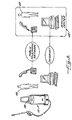
- FIG. 4 is a schematic diagram showing a power cord of an embodiment of the pressure washer with a plug having a built-in ground fault circuit interrupter (GFCI) and wiring for markets where GFCI is not required;
- GFCI ground fault circuit interrupter
- FIG. 5 is a schematic diagram showing an optically coupled sensing circuit over a breaker of the GFCI for sensing whether AC power is present at the plug;
- FIG. 6 is an electronic circuit schematic diagram showing a diagnostic circuit in the pressure washer for detecting operation conditions of the pressure washer and operating light-emitting diodes to indicate the detected operation conditions;
- FIG. 7 is a schematic diagram showing a pressure washer of an embodiment that transmits RF signals for wireless communication with a monitoring device.
- FIG. 8 is a schematic diagram showing a pressure washer of another embodiment that has a global positioning system module.
- an electrical pressure washer 10 in an embodiment of the invention includes a housing 11 that contains an electrical motor 12 ( FIG. 2 ) for pressurizing water received from a low-pressure water source through a water inlet 13 ( FIG. 2 ) to provide an output high-pressure water stream.
- a power cord 14 of a pre-selected length connects the pressure washer to an AC outlet 16 from which the pressure washer draws the power needed for operating the motor.
- An on/off switch 17 on the housing 11 of the pressure washer is used to turn the pressure washer on or off by connecting or breaking the AC power to the motor.
- On the distal end of the power cord 14 is an AC plug 18 to be plugged into a receptacle of the AC outlet 16 .
- the power cord includes a ground fault circuit interrupter (GFCI) 20 that is integrated with the AC plug 18 .
- the GFCI is not required, however, in regions where the electrical safety code does not call for such a device.
- the pressure washer 10 further includes a flexible high-pressure hose 21 .
- One end of the pressure hose has a connector 22 that can be connected to a fitting 24 on the housing to form a leak-proof connection.
- the other end of the hose 21 is connected to an application wand 25 with a trigger 26 for opening or closing a valve in the wand to control the water flow.
- the pressure washer further includes a nozzle 28 that can be connected to the wand 25 such that pressurized water is ejected through an output opening 29 of the nozzle when the user pulls the trigger 26 on the wand 25 .
- the size of the output opening 29 of the nozzle 28 is preferably adjustable to allow the pressurized water stream coming out of the nozzle to be adjusted from a wide “fan” spray to a focused pencil-thin stream.
- the pressure washer includes a chemical tank 31 for containing the liquid detergent 32 .
- a vacuum generated by the pressurized water pumped out through the nozzle 28 is used to provide suction of the detergent from the chemical tank.
- the detergent extracted by the vacuum from the chemical tank is mixed with the water stream and ejected through the nozzle 28 .
- the operation of the pressure washer 10 is affected by various factors, and there are multiple conditions that will make the pressure washer appear that it is not function properly. Such conditions are often difficult to understand or identify by an inexperienced user who has not read the manual for the pressure washer or cannot comprehend the explanations and instructions in the manual. As a result, the user tends to assume that the pressure washer is broken or faulty, even though some of the conditions affecting the performance of the machine can be easily corrected. For instance, if the GFCI 20 on the plug 18 of the power cord is tripped, AC power is cut off at the plug end of the power cord, and the pressure washer 10 cannot be turned on by operating the on/off switch 17 on the housing.
- a diagnostic circuit 36 is provided in the electrical pressure washer 10 for detecting operating conditions of the pressure washer, and a diagnostic indication panel 38 is provided with indicator lights 39 to indicate the detected operation conditions for viewing by the user.
- the diagnostic indication panel 38 allows the user to see easily the operating conditions of the washer, so that the user can take proper corrective actions based on the diagnostic information shown by the indicator lights. For instance, if an indicator light shows that the GFCI 20 is tripped, the user can correct the problem easily by resetting the GFCI. Information about which action to take based on which indicator light is on or off may be provided in a trouble shooting chapter in the user's manual for the pressure washer.
- the indicator lights allows the user to report the problem to a remote service center, which can then identify the possible causes of the problem based on the status of the indicator lights. For instance, as shown in FIG. 3 , the user 40 can contact a service center 42 of the manufacturer via telephone and tells the service representative 43 the On/Off states of the indicator lights in the diagnostic indicator panel 38 of the pressure washer. Based on that information, the service representative 43 can make a decision or informed guess of what the cause of the problem may be, and give the user instructions over the telephone to try various corrective measures to change the operation conditions to put the pressure washer back in the normal operation mode.
- the user 40 can have the problem corrected easily and promptly. As a result, the user is much less likely to unnecessarily return the machine to the shop, send the machine in for repair, or call for a visit by a service person.
- the contacts between the user 40 and the service center 42 is, of course, not limited to a telephone conversation and can be made via, for example, e-mail or video conferencing over the Internet, or other forms of remote communications.
- the diagnostic circuit is mounted inside the housing 11 of the pressure washer.
- the diagnostic circuit 36 operates indicator lights 39 in the diagnostic indication panel 38 , which is mounted on the housing at a location that is easily viewable but well protected from accidental impact.
- the diagnostic indication panel 38 is located on the upper front surface of the housing adjacent a handle 15 of the pressure washer.
- the indicator panel 38 includes lights for indicating, for example, the presence of the AC power at the GFCI plug, the AC voltage seen by the motor, whether the over-temperature protection for the motor is on, whether the pressure washer is in the chemical suction mode, etc. Indicators for other types of operation conditions may also be included.
- the amount of electrical current drawn by the motor 12 of the pressure washer is detected and used to determine several operation conditions of the pressure washer.
- the amount of the electrical current is determined by detecting the voltage drop across one of the power conductors in the power cord 14 .
- the voltage drop is measured across the Return wire of the power cord.
- the plug 18 with integral GFCI receives the Hot, Return, and Ground components of the standard AC voltage (e.g., 120V) from a wall outlet or the like.
- the power cord 14 connecting the plug to the pressure washer main body includes a Hot wire 50 , a Return wire 51 , and a Ground wire 52 .
- the voltage drop across the Return wire 51 provides a useful indication of the current drawn by the motor 12 .
- a 36.5-foot Return wire of 16 AWG has a resistance of about 0.173 ohm. With a current draw of 9-17 Amps, a voltage drop of about 1.5-3 Vrms is created over the Return wire.
- the detected voltage drop over the Return wire 51 divided by the known resistance of the wire provides the amount of current flowing through the wire.
- a sensing wire 54 is added to the standard three wires 50 - 52 of the power cord 14 and runs along the three wires.
- the power cord 14 now contains four wires: Hot, Return, Neutral, and the sensing wire.
- the sensing wire 54 allows the diagnostic circuit 36 to detect the voltage on the Return wire at the remote plug end of the power cord.
- the sensing wire further allows the diagnostic circuit 18 to detect whether the AC power is present at the plug 18 before the GFCI breaker 56 . Since for safety reasons the sensing wire 54 should not have a direct electrical contact with the plug input upstream of the GFCI breaker 56 , an optical coupling assembly 57 is used to sense the presence of AC power. As shown in FIG. 5 , a light emitting circuit 56 comprising a simple power supply and a light-emitting diode (LED) 59 is connected across the Hot terminal 61 and Return terminal 62 at the input end of the plug 18 . When AC power is present at the plug upstream of the GFCI, the LED 59 is energized to emit light.
- a light emitting circuit 56 comprising a simple power supply and a light-emitting diode (LED) 59 is connected across the Hot terminal 61 and Return terminal 62 at the input end of the plug 18 .
- the sensing wire 54 is connected to a phototransistor 60 that is positioned to receive the light generated by the LED 59 . If the LED 59 is on, the phototransistor 60 is turned on by the light received from the LED. On the other hand, if the LED 59 is off due to the absence of an AC voltage between the Hot and Return terminals 61 and 62 , the phototransistor 60 is off. Based on the on/off state of the phototransistor 60 as sensed through the sensing wire 54 , the diagnostic circuit 18 can decide whether AC power is present at the plug input.
- the detection of the presence of AC power at the plug before the GFCI in turn allows the diagnostic circuit to determine whether the GFCI breaker 56 is open. If AC power is present at the plug but not at the motor, the diagnostic circuit 18 can deduce that the GFCI breaker 56 is open, and can indicate this condition by turning on an indicator light 70 marked “Check GFCI.” On the other hand, if no AC power is detected at the plug input, the diagnostic circuit turns on a “No AC” indicator light 71 to indicate that there is no AC power. This condition may occur if, for instance, the user forgets to connect the plug to a wall outlet or if a circuit breaker before the wall outlet is open.
- a backup capacitor 80 of a sufficiently large value (e.g., 0.1 farad) is used in the diagnostic circuit to store energy. If the On/Off switch 17 on the pressure washer is in the On position but the AC power to the pressure washer is cut off, the capacitor 80 is automatically switched in to power the components of the diagnostic circuit 36 .
- the diagnostic circuit includes LED's 70 - 77 that are marked respectively on the display panel ( FIG. 1 ) as “Check GFCI,” “No AC Power,” “AC OK,” “AC Low,” “Motor OK,” “Detergent ON,” “Low Water Flow,” and “Motor Over-temperature,” respectively.
- low-cost operational amplifies (OpAmp) 81 - 84 are used to detect the different operation conditions.
- the OpAmps 81 - 84 are of a low-power type to further reduce the power consumption of the diagnostic circuit.
- the OpAMps 81 - 84 are connected to respective indicator LED's 72 - 76 to selectively turn the LED's on or off depending on the operation conditions detected.
- the OpAmps 81 - 84 are used basically as voltage comparators.
- Each OpAmp compares an input voltage with a reference voltage (via appropriate voltage dividers), which is provided by a zener diode 88 (DIODE 16) in the circuit of FIG. 6 .
- the input voltage for each OpAmp is a voltage derived from voltages detected in the electrical system of the pressure washer. Such detected voltages include the AC power voltages and, as mentioned above, the voltage drop over the Return wire as detected through the sensing wire.
- the voltage detected through the sensing wire enables the determination of multiple operation conditions.
- the sensed voltage at the plug end of the power cord 14 is used together with the voltage detected at the motor to determine whether there is no AC power at the plug 18 or the GFCI breaker 56 may be open.
- the circuit of FIG. 1 In the circuit of FIG. 1
- the voltage drop over the Return wire is further used to determine whether the motor is in normal operation condition (i.e., “Motor OK”), whether the pressure washer is in the chemical suction mode (i.e., “Detergent On”), whether the inlet water pressure is low (i.e., “Low Water Flow”), or whether the thermal protection circuit for the motor is opened to prevent the motor from overheating (i.e., “Motor Over-temperature”).
- the voltage drop over the Return wire can be used to determine the root mean square (rms) value of the current following through the motor 12 of the pressure washer.
- the root mean square values of the current drawn by the motor 12 corresponding to these four operation conditions fall into four separate ranges.
- the motor current stays in a high-current range, and varies depending to different degrees on the AC rms voltage at the motor, the type of nozzle used, and the shape of the output water stream at the nozzle.
- the motor current is significantly lower than that of the normal operation.
- the inlet water pressure is low, the low water flow causes the motor current to fluctuate rapidly, but the averaged value of the motor current is fairly stable and stays below the motor current in the chemical suction mode, thus providing a good indication of the presence of the low inlet pressure condition.
- the thermal protection circuit in the motor winding is opened, the motor is not drawing any current. The lack of motor current together with the detection that the AC voltage is detected at the motor indicates that the thermal protection circuit in the motor may be opened.
- the LED's 72 - 77 are connected in series such that the same current (hereinafter “the indicator current”) can flow through selected LED's to turn those LED's on.
- the efficiency of power usage is further enhanced by using the indicator current 90 to charge the backup capacitor 80 by connecting the capacitor in series to the chain of LED's.
- the indicator current flows through one or more of the LED's 72 - 77 depending on the operation conditions detected by the OpAmps 81 - 84 , and flows into the backup capacitor 80 to charge the capacitor until the voltage across the capacitor reaches a value set by the zener diode 91 .
- the energy stored in the backup capacitor 80 is used to power the operation of the diagnostic circuit 36 to turn either of the LED's 70 and 71 on to indicate to the user that the GFCI should be checked or there is no AC power at the plug 18 .
- a plurality of bypass transistors 92 - 97 are provided such that each LED has a corresponding bypass transistor connected in parallel therewith.
- the bypass transistor When the bypass transistor is turned on, the indicator current will flow through the bypass transistor instead of the LED. As a result, the LED is turned off, i.e., it does not emit light.
- the On/Off state of the bypass transistor is controlled by an associated OpAmp depending on whether the operating condition monitored by that OpAmp is present. By way of example, if the pressure washer is being used and the motor 12 is running normally, the voltage drop over the Return wire is of a value indicating that the motor current is in the high range.
- the voltage drop is presented as one of the input voltages for the OpAmp 82 .
- the other input voltage is derived from the reference voltage via a voltage divider.
- the input voltages for the OpAmp 82 cause the output voltage of the OpAmp to be at a low value that turns the bypass transistor 94 off. With the bypass transistor 94 turned off, the indication current flows through the LED 74 . As a result, the LED 74 generates light to indicate that the motor is operating normally.
- a pressure washer 100 is equipped with a communication circuit 101 .
- the communication circuit controls a radio frequency (RF) transceiver 102 to send and receive radio frequency signals.
- the wireless communication capability of the pressure washer 100 can be used for various purposes.
- the RF communication circuit may serve the function of a tracking device.
- the communication circuit may be programmed to transmit the serial number of the pressure washer, and/or other information that may be used to identify the pressure washer.
- the RF transmission may be received by a receiver at a service center 103 , or by a mobile monitoring device 104 .
- the RF transmission may also include diagnostic data indicative of the operation conditions detected by the diagnostic circuit 36 . This enables the receiver of the RF transmission from the machine to determine the status of the pressure washer in the field and, if necessary, to contact the user of the pressure washer to correct the problem to restore the normal operation of the washer.
- the pressure washer may be equipped with a modem 105 .
- the communication circuit 101 is programmed such that it automatically dials up to a pre-programmed number of the service center 103 when the modem is plugged into a telephone line. Once the phone connection is made, the communication circuit 101 transmits information including the serial number of the pressure washer and the operation conditions. This enables a service technician 106 at the service center 103 to identify the potential problems of the unit without having to physically examine the machine.
- the pressure washer 110 is further equipped with a global positioning system (GPS) module 111 .
- the GPS module 111 receives radio signals from GPS satellites 112 . By triangulation of signals from three of the GPS satellites 112 the GPS module 111 can pinpoint its current location.
- the communication circuit 101 of the pressure washer 110 then transmits RF signals containing information of its current location, its identification, and its operational status as detected by the diagnostic circuit 36 .
- the transmission and reception of the RF signals may utilize the infrastructure provided by a cellular phone network.
- the service technician 106 can learn the identity of the pressure washer, where the machine is, and whether the machine is operating properly.
- the RF transmission sent by the communication circuit 101 of the pressure washer can be used to track the location of the pressure washer, and the identification information encoded in the transmission allows the receiver to identify the pressure washer.
- the identification information in the wireless transmission also allows the monitoring device to remotely monitor the inventory of pressure washers at a store.
- the GPS locator function of the machine may be activated at the time the pressure washer 110 is purchased by a customer at a store.
- the GPS locating transmission from the pressure washer 10 may also be triggered in response to commands sent remotely by the service center 103 over RF transmission.
Abstract
Description
Claims (21)
Priority Applications (5)
| Application Number | Priority Date | Filing Date | Title |
|---|---|---|---|
| US10/790,527 US8074668B2 (en) | 2004-03-01 | 2004-03-01 | Pressure washer with diagnostic indicators |
| CA002556637A CA2556637A1 (en) | 2004-03-01 | 2005-03-01 | Pressure washer with diagnostic indicators |
| PCT/US2005/006570 WO2005084302A2 (en) | 2004-03-01 | 2005-03-01 | Pressure washer with diagnostic indicators |
| CNA2005800064337A CN101102855A (en) | 2004-03-01 | 2005-03-01 | Pressure washer with diagnostic indicators |
| EP05724165A EP1735115A4 (en) | 2004-03-01 | 2005-03-01 | Pressure washer with diagnostic indicators |
Applications Claiming Priority (1)
| Application Number | Priority Date | Filing Date | Title |
|---|---|---|---|
| US10/790,527 US8074668B2 (en) | 2004-03-01 | 2004-03-01 | Pressure washer with diagnostic indicators |
Publications (2)
| Publication Number | Publication Date |
|---|---|
| US20050189437A1 US20050189437A1 (en) | 2005-09-01 |
| US8074668B2 true US8074668B2 (en) | 2011-12-13 |
Family
ID=34887500
Family Applications (1)
| Application Number | Title | Priority Date | Filing Date |
|---|---|---|---|
| US10/790,527 Expired - Fee Related US8074668B2 (en) | 2004-03-01 | 2004-03-01 | Pressure washer with diagnostic indicators |
Country Status (5)
| Country | Link |
|---|---|
| US (1) | US8074668B2 (en) |
| EP (1) | EP1735115A4 (en) |
| CN (1) | CN101102855A (en) |
| CA (1) | CA2556637A1 (en) |
| WO (1) | WO2005084302A2 (en) |
Cited By (5)
| Publication number | Priority date | Publication date | Assignee | Title |
|---|---|---|---|---|
| US8931513B1 (en) * | 2012-07-31 | 2015-01-13 | Ricky H Holley | Water supply shut-off system |
| US9283580B2 (en) | 2014-01-17 | 2016-03-15 | Calvin Ross ISLEY | Car wash wand with LED light |
| US11020767B2 (en) | 2016-03-28 | 2021-06-01 | Graco Minnesota Inc. | Operator interface device for a plural component dispensing system |
| US11750954B2 (en) | 2013-02-11 | 2023-09-05 | Graco Minnesota Inc. | Remote monitoring for fluid applicator system |
| US11815919B2 (en) | 2013-02-11 | 2023-11-14 | Graco Minnesota Inc. | Operator interface device and distributed control for fluid dispensing systems |
Families Citing this family (25)
| Publication number | Priority date | Publication date | Assignee | Title |
|---|---|---|---|---|
| ITRE20020023U1 (en) * | 2002-07-25 | 2004-01-26 | Annovi Reverberi Spa | DEVICE FOR THE PROCESSING OF THE PRESSURE OF THE FLUID DELIVERED BY A HIGH PRESSURE CLEANER |
| US7891036B2 (en) * | 2005-03-18 | 2011-02-22 | Techtronic Outdoor Products Technology Limited | Multi-function power washer |
| DE102005063294A1 (en) * | 2005-09-16 | 2007-06-06 | Büsselmann, Manfred | Water explosion engine procedure and device |
| RU2425986C2 (en) | 2005-11-30 | 2011-08-10 | Манфред БЮССЕЛЬМАНН | Drive and method to drive engine |
| US20090183689A1 (en) * | 2008-01-22 | 2009-07-23 | Gary Stephen Moore | Portable, rechargeable insect control apparatus and method of operation |
| WO2009132316A1 (en) * | 2008-04-24 | 2009-10-29 | Homelite Technologies Ltd. | Surface cleaner system |
| US8783587B2 (en) * | 2011-03-14 | 2014-07-22 | Karcher North America, Inc. | Mobile washer unit |
| US8602323B2 (en) | 2011-03-14 | 2013-12-10 | Karcher North America | Mobile washer unit |
| US20130025316A1 (en) * | 2011-07-29 | 2013-01-31 | Justin Wheeless | Ice Cooler With Power Wash |
| US9945616B1 (en) | 2013-05-28 | 2018-04-17 | Patrick G. Wingen | Waste heat recovery system for a fluid heater |
| USD749805S1 (en) | 2013-10-08 | 2016-02-16 | Briggs & Stratton Corporation | Pressure washer |
| USD742080S1 (en) | 2013-10-16 | 2015-10-27 | Briggs & Stratton Corporation | Pressure washer |
| US9254856B2 (en) * | 2014-01-24 | 2016-02-09 | Robert Bosch Gmbh | Quick service cart |
| US10549131B2 (en) | 2014-07-29 | 2020-02-04 | C.J. Spray, Inc. | Apparatus, components, methods and techniques for controlling equipment operation |
| JP6517334B2 (en) * | 2014-10-30 | 2019-05-22 | アルフレッド ケルヒャー エスエー ウント コンパニー カーゲー | High pressure cleaning system and method for operating high pressure cleaning system |
| USD781010S1 (en) * | 2015-04-09 | 2017-03-07 | Alfred Kaercher Gmbh & Co. Kg | High-pressure cleaner |
| USD781511S1 (en) * | 2015-04-09 | 2017-03-14 | Alfred Kaercher Gmbh & Co. Kg | High-pressure cleaner |
| JP1602829S (en) * | 2015-08-10 | 2018-04-23 | ||
| CN106914439B (en) * | 2015-12-28 | 2021-01-05 | 苏州宝时得电动工具有限公司 | Pressure cleaning machine |
| CN107872989B (en) * | 2015-12-28 | 2021-08-10 | 苏州宝时得电动工具有限公司 | Pressure cleaning machine and spray rod identification method thereof |
| US20190210074A1 (en) * | 2016-09-07 | 2019-07-11 | Sunrise Global Marketing | Pressure washer and method of operating a pressure washer with electronic pressure/flow control and display |
| USD894505S1 (en) * | 2017-10-18 | 2020-08-25 | Changzhou Globe Co., Ltd. | Pressure washer |
| USD918499S1 (en) * | 2019-01-30 | 2021-05-04 | Ningbo Yinzhou Jiasheng Pump Electric Machinery Factory | Pressure washer |
| USD931560S1 (en) * | 2019-01-30 | 2021-09-21 | Ningbo Yinzhou Jiasheng Pump Electric Machinery Factory | Pressure washer |
| US11697137B2 (en) | 2019-03-23 | 2023-07-11 | Tennant Company | Mobile surface maintenance machine with an onboard pressure washer |
Citations (10)
| Publication number | Priority date | Publication date | Assignee | Title |
|---|---|---|---|---|
| DE227568C (en) * | ||||
| US4697464A (en) * | 1986-04-16 | 1987-10-06 | Martin Thomas E | Pressure washer systems analyzer |
| US5040950A (en) * | 1989-08-07 | 1991-08-20 | Northland Aluminum Products, Inc. | Power washing apparatus |
| US5220935A (en) | 1990-12-28 | 1993-06-22 | Carolina Equipment & Supply Co., Inc. | Apparatus and method for cleaning with a focused fluid stream |
| US5381962A (en) * | 1992-12-10 | 1995-01-17 | Hydro-Chem Systems, Inc. | Remote controlled spraying device |
| US5661623A (en) | 1993-09-02 | 1997-08-26 | Hubbell Corporation | Ground fault circuit interrupter plug |
| US5745043A (en) * | 1996-10-15 | 1998-04-28 | Clarke Industries, Inc. | Indicator junction module for pressure washer |
| US5749526A (en) * | 1995-08-28 | 1998-05-12 | Gary R. Laabs | Centrally installed cleaning/washing system for buildings |
| US5757162A (en) * | 1996-02-28 | 1998-05-26 | Weber; Harold J. | Method and apparatus for operating an electric induction motor with a long and lossy extension cord |
| DE10029375A1 (en) | 2000-06-20 | 2002-03-14 | Hammelmann Paul Maschf | Control device for a high pressure cleaning device |
-
2004
- 2004-03-01 US US10/790,527 patent/US8074668B2/en not_active Expired - Fee Related
-
2005
- 2005-03-01 CN CNA2005800064337A patent/CN101102855A/en active Pending
- 2005-03-01 WO PCT/US2005/006570 patent/WO2005084302A2/en active Application Filing
- 2005-03-01 EP EP05724165A patent/EP1735115A4/en not_active Withdrawn
- 2005-03-01 CA CA002556637A patent/CA2556637A1/en not_active Abandoned
Patent Citations (10)
| Publication number | Priority date | Publication date | Assignee | Title |
|---|---|---|---|---|
| DE227568C (en) * | ||||
| US4697464A (en) * | 1986-04-16 | 1987-10-06 | Martin Thomas E | Pressure washer systems analyzer |
| US5040950A (en) * | 1989-08-07 | 1991-08-20 | Northland Aluminum Products, Inc. | Power washing apparatus |
| US5220935A (en) | 1990-12-28 | 1993-06-22 | Carolina Equipment & Supply Co., Inc. | Apparatus and method for cleaning with a focused fluid stream |
| US5381962A (en) * | 1992-12-10 | 1995-01-17 | Hydro-Chem Systems, Inc. | Remote controlled spraying device |
| US5661623A (en) | 1993-09-02 | 1997-08-26 | Hubbell Corporation | Ground fault circuit interrupter plug |
| US5749526A (en) * | 1995-08-28 | 1998-05-12 | Gary R. Laabs | Centrally installed cleaning/washing system for buildings |
| US5757162A (en) * | 1996-02-28 | 1998-05-26 | Weber; Harold J. | Method and apparatus for operating an electric induction motor with a long and lossy extension cord |
| US5745043A (en) * | 1996-10-15 | 1998-04-28 | Clarke Industries, Inc. | Indicator junction module for pressure washer |
| DE10029375A1 (en) | 2000-06-20 | 2002-03-14 | Hammelmann Paul Maschf | Control device for a high pressure cleaning device |
Non-Patent Citations (2)
| Title |
|---|
| EP Supplementary Search Report for EP Application No. EP 05724165 dated Jul. 15, 2011. |
| U.S. Patent & Trademark Office, International Search Report in International Patent Application No. PCT/US2005/006570 (Dec. 18, 2006). |
Cited By (5)
| Publication number | Priority date | Publication date | Assignee | Title |
|---|---|---|---|---|
| US8931513B1 (en) * | 2012-07-31 | 2015-01-13 | Ricky H Holley | Water supply shut-off system |
| US11750954B2 (en) | 2013-02-11 | 2023-09-05 | Graco Minnesota Inc. | Remote monitoring for fluid applicator system |
| US11815919B2 (en) | 2013-02-11 | 2023-11-14 | Graco Minnesota Inc. | Operator interface device and distributed control for fluid dispensing systems |
| US9283580B2 (en) | 2014-01-17 | 2016-03-15 | Calvin Ross ISLEY | Car wash wand with LED light |
| US11020767B2 (en) | 2016-03-28 | 2021-06-01 | Graco Minnesota Inc. | Operator interface device for a plural component dispensing system |
Also Published As
| Publication number | Publication date |
|---|---|
| CA2556637A1 (en) | 2005-09-15 |
| EP1735115A2 (en) | 2006-12-27 |
| CN101102855A (en) | 2008-01-09 |
| WO2005084302A2 (en) | 2005-09-15 |
| WO2005084302A3 (en) | 2007-03-22 |
| EP1735115A4 (en) | 2011-08-24 |
| US20050189437A1 (en) | 2005-09-01 |
Similar Documents
| Publication | Publication Date | Title |
|---|---|---|
| US8074668B2 (en) | Pressure washer with diagnostic indicators | |
| US6526807B1 (en) | Early warning water leak detection system | |
| US6147613A (en) | Early warning water leak detection system | |
| US7414818B2 (en) | Receptacle type ground-fault circuit interrupter | |
| KR100633779B1 (en) | Green consent | |
| US20120007621A1 (en) | Circuit interrupter device with self-test function | |
| KR20080103193A (en) | Multi-tab for cutting off the standby-power and method for cutting off the standby-power using the multi-tab | |
| CA2301867A1 (en) | Water leakage protector apparatus | |
| EA034860B1 (en) | Apparatuses and methods for controlling power to electronic devices | |
| WO2010080704A2 (en) | Washing machine flood prevention system | |
| US7246640B2 (en) | Fuel-discharge protection system for preventing electrostatic hazard | |
| US7103270B1 (en) | Steam cleaner with multiple protections | |
| TWI515988B (en) | Leakage protection circuit, socket using same, and electronic decive | |
| US6615056B1 (en) | Method and apparatus to protect fixed wireless terminal from foreign voltage at the tip and ring connection | |
| US4987408A (en) | Water sensor system | |
| WO2015032361A1 (en) | Handheld fuel distributor control device with current-limiting battery pack | |
| CN110473343A (en) | Self-service machine and its monitoring method out of stock | |
| JP2001137158A (en) | Central cleaner | |
| MXPA06010067A (en) | Pressure washer with diagnostic indicators | |
| JP2008102065A (en) | Gas shut-off device | |
| JP2930333B2 (en) | Power plug disconnection detection device | |
| JP2010249422A (en) | Gas appliance monitor | |
| CN110751813A (en) | Gas alarm system based on infrared imaging | |
| CN210534303U (en) | Grounding detection device of metal shell for equipment and outdoor unit | |
| JP2545607Y2 (en) | Gas leak alarm shutoff device |
Legal Events
| Date | Code | Title | Description |
|---|---|---|---|
| AS | Assignment |
Owner name: FAIP NORTH AMERICA, INC., ILLINOIS Free format text: ASSIGNMENT OF ASSIGNORS INTEREST;ASSIGNORS:ALEXANDER, GUS;HANSEN, MIKE C.;REEL/FRAME:015652/0938 Effective date: 20040301 |
|
| AS | Assignment |
Owner name: FNA IP HOLDINGS, INC., ILLINOIS Free format text: CHANGE OF NAME;ASSIGNOR:FAIP NORTH AMERICA, INC.;REEL/FRAME:022990/0516 Effective date: 20081031 Owner name: FNA IP HOLDINGS, INC.,ILLINOIS Free format text: CHANGE OF NAME;ASSIGNOR:FAIP NORTH AMERICA, INC.;REEL/FRAME:022990/0516 Effective date: 20081031 |
|
| AS | Assignment |
Owner name: HARRIS N.A., ILLINOIS Free format text: SECURITY AGREEMENT;ASSIGNOR:FNA IP HOLDINGS, INC.;REEL/FRAME:023032/0808 Effective date: 20090731 Owner name: HARRIS N.A.,ILLINOIS Free format text: SECURITY AGREEMENT;ASSIGNOR:FNA IP HOLDINGS, INC.;REEL/FRAME:023032/0808 Effective date: 20090731 |
|
| ZAAA | Notice of allowance and fees due |
Free format text: ORIGINAL CODE: NOA |
|
| ZAAB | Notice of allowance mailed |
Free format text: ORIGINAL CODE: MN/=. |
|
| STCF | Information on status: patent grant |
Free format text: PATENTED CASE |
|
| AS | Assignment |
Owner name: BANK OF AMERICA, N.A., ILLINOIS Free format text: SECURITY AGREEMENT;ASSIGNOR:FNA IP HOLDINGS, INC.;REEL/FRAME:030370/0366 Effective date: 20130430 Owner name: FNA IP HOLDINGS, INC., ILLINOIS Free format text: RELEASE BY SECURED PARTY;ASSIGNOR:BMO HARRIS BANK N.A., FORMERLY KNOWN AS HARRIS N.A.;REEL/FRAME:030366/0651 Effective date: 20130430 |
|
| FPAY | Fee payment |
Year of fee payment: 4 |
|
| AS | Assignment |
Owner name: FNA GROUP, INC., WISCONSIN Free format text: ASSIGNMENT OF ASSIGNORS INTEREST;ASSIGNOR:FNA IP HOLDINGS, INC.;REEL/FRAME:037223/0201 Effective date: 20151125 |
|
| MAFP | Maintenance fee payment |
Free format text: PAYMENT OF MAINTENANCE FEE, 8TH YR, SMALL ENTITY (ORIGINAL EVENT CODE: M2552); ENTITY STATUS OF PATENT OWNER: SMALL ENTITY Year of fee payment: 8 |
|
| FEPP | Fee payment procedure |
Free format text: MAINTENANCE FEE REMINDER MAILED (ORIGINAL EVENT CODE: REM.); ENTITY STATUS OF PATENT OWNER: SMALL ENTITY |
|
| LAPS | Lapse for failure to pay maintenance fees |
Free format text: PATENT EXPIRED FOR FAILURE TO PAY MAINTENANCE FEES (ORIGINAL EVENT CODE: EXP.); ENTITY STATUS OF PATENT OWNER: SMALL ENTITY |
|
| STCH | Information on status: patent discontinuation |
Free format text: PATENT EXPIRED DUE TO NONPAYMENT OF MAINTENANCE FEES UNDER 37 CFR 1.362 |
|
| FP | Lapsed due to failure to pay maintenance fee |
Effective date: 20231213 |