US8072996B2 - Multiple-buffer queueing of data packets with high throughput rate - Google Patents
Multiple-buffer queueing of data packets with high throughput rate Download PDFInfo
- Publication number
- US8072996B2 US8072996B2 US11/924,340 US92434007A US8072996B2 US 8072996 B2 US8072996 B2 US 8072996B2 US 92434007 A US92434007 A US 92434007A US 8072996 B2 US8072996 B2 US 8072996B2
- Authority
- US
- United States
- Prior art keywords
- chunk
- memory
- packet
- data
- buffer memory
- Prior art date
- Legal status (The legal status is an assumption and is not a legal conclusion. Google has not performed a legal analysis and makes no representation as to the accuracy of the status listed.)
- Expired - Fee Related, expires
Links
- 239000000872 buffer Substances 0.000 title claims abstract description 154
- 230000015654 memory Effects 0.000 claims abstract description 174
- 238000000034 method Methods 0.000 claims abstract description 11
- 230000001360 synchronised effect Effects 0.000 claims description 6
- 230000003068 static effect Effects 0.000 claims description 5
- 230000003139 buffering effect Effects 0.000 claims description 4
- 230000004044 response Effects 0.000 claims 9
- 238000010586 diagram Methods 0.000 description 27
- 230000005540 biological transmission Effects 0.000 description 6
- 239000004744 fabric Substances 0.000 description 6
- 230000008901 benefit Effects 0.000 description 3
- 230000001052 transient effect Effects 0.000 description 3
- 239000000284 extract Substances 0.000 description 2
- 239000000835 fiber Substances 0.000 description 2
- 238000005204 segregation Methods 0.000 description 2
- 238000013459 approach Methods 0.000 description 1
- 238000009432 framing Methods 0.000 description 1
- 238000012986 modification Methods 0.000 description 1
- 230000004048 modification Effects 0.000 description 1
- 230000003287 optical effect Effects 0.000 description 1
- 239000013307 optical fiber Substances 0.000 description 1
- 230000008520 organization Effects 0.000 description 1
- 239000004065 semiconductor Substances 0.000 description 1
Images


Classifications
-
- H—ELECTRICITY
- H04—ELECTRIC COMMUNICATION TECHNIQUE
- H04L—TRANSMISSION OF DIGITAL INFORMATION, e.g. TELEGRAPHIC COMMUNICATION
- H04L49/00—Packet switching elements
- H04L49/90—Buffering arrangements
- H04L49/901—Buffering arrangements using storage descriptor, e.g. read or write pointers
-
- H—ELECTRICITY
- H04—ELECTRIC COMMUNICATION TECHNIQUE
- H04L—TRANSMISSION OF DIGITAL INFORMATION, e.g. TELEGRAPHIC COMMUNICATION
- H04L49/00—Packet switching elements
- H04L49/90—Buffering arrangements
-
- H—ELECTRICITY
- H04—ELECTRIC COMMUNICATION TECHNIQUE
- H04L—TRANSMISSION OF DIGITAL INFORMATION, e.g. TELEGRAPHIC COMMUNICATION
- H04L49/00—Packet switching elements
- H04L49/90—Buffering arrangements
- H04L49/9021—Plurality of buffers per packet
-
- H—ELECTRICITY
- H04—ELECTRIC COMMUNICATION TECHNIQUE
- H04L—TRANSMISSION OF DIGITAL INFORMATION, e.g. TELEGRAPHIC COMMUNICATION
- H04L49/00—Packet switching elements
- H04L49/90—Buffering arrangements
- H04L49/9042—Separate storage for different parts of the packet, e.g. header and payload
-
- H—ELECTRICITY
- H04—ELECTRIC COMMUNICATION TECHNIQUE
- H04J—MULTIPLEX COMMUNICATION
- H04J2203/00—Aspects of optical multiplex systems other than those covered by H04J14/05 and H04J14/07
- H04J2203/0001—Provisions for broadband connections in integrated services digital network using frames of the Optical Transport Network [OTN] or using synchronous transfer mode [STM], e.g. SONET, SDH
- H04J2203/0073—Services, e.g. multimedia, GOS, QOS
- H04J2203/0082—Interaction of SDH with non-ATM protocols
Definitions
- This invention relates to computer networks.
- the invention relates to data buffering in computer networks.
- SONET Synchronous Optical Network
- WAN Wide Area Network
- Popular standards include OC-3c (155 Mbps), OC-12c (622 Mbps), OC-48c (2.5 Gbps), OC-192c (10 Gbps), OC-768c (40 Gbps), etc.
- the present invention is a method and apparatus to buffer data.
- a buffer memory of a first type stores data associated with a connection identifier corresponding to a channel in a network. The data is organized into at least one chunk based on a linked list.
- the connection identifier identifies a connection in the channel.
- the data is part of a data stream associated with the connection.
- a packet memory of a second type provides access to the stored data when a transfer condition occurs.
- FIG. 1 is a diagram illustrating a system in which one embodiment of the invention can be practiced.
- FIG. 2 is a diagram illustrating a data buffer circuit according to one embodiment of the invention.
- FIG. 3A is a diagram illustrating a linked list used in organizing the data according to one embodiment of the invention.
- FIG. 3B is a diagram illustrating a collapse operation on the chunks according to one embodiment of the invention.
- FIG. 3C is a diagram illustrating an expansion operation on the chunks according to one embodiment of the invention.
- FIG. 4 is a diagram illustrating an input buffer memory according to one embodiment of the invention.
- FIG. 5 is a diagram illustrating a controller according to one embodiment of the invention.
- FIG. 6 is a diagram illustrating a data transfer for long packets according to one embodiment of the invention.
- FIG. 7 is a diagram illustrating a data transfer for short packets according to one embodiment of the invention.
- FIG. 8A is a diagram illustrating a data transfer path to the input buffer memory for long packets according to one embodiment of the invention.
- FIG. 8B is a diagram illustrating a data transfer path to the packet memory and the output buffer memory for long packets according to one embodiment of the invention.
- FIG. 8C is a diagram illustrating a data transfer path for the data blocks to the output buffer memory for long packets according to one embodiment of the invention.
- FIG. 8D is a diagram illustrating a data transfer path to the controller for long packets according to one embodiment of the invention.
- the present invention is a method and apparatus to buffer data (e.g., transient network data).
- a buffer memory of a first type stores data associated with a connection identifier corresponding to a channel in a network. The data is organized into at least one chunk based on a linked list.
- the connection identifier identifies a connection in the channel.
- the data from the network connection is stored in a virtual queue implemented as a linked list of fixed sized data chunks.
- the data is part of a data stream associated with the connection.
- a packet memory of a second type provides access to the stored data when a transfer condition occurs.
- the apparatus includes a descriptor memory and a controller.
- the descriptor memory stores descriptor information corresponding to the chunks.
- the controller controls data transfer between the buffer memory and the packet memory using the descriptor information.
- the chunk includes a chunk header and a chunk data block.
- the chunk header stores chunk information associated with the linked list and the chunk data block stores the data.
- the chunk header information includes a pointer to point to one other chunk, a size specifier to specify size of the chunk, and a type specifier to specify type of the chunk.
- the chunk may be a head chunk corresponding to the beginning of a data stream, a linking chunk corresponding to an intermediate portion of the data stream, or a tail chunk corresponding to the end of a data stream.
- the descriptor information includes one head pointer and one tail pointer pointing to the head and tail chunks, respectively.
- the data transfer is performed by combining the data blocks of the chunks into a large data block.
- the large data block can then be burst written to or burst read from the pocket memory using the burst mode of the synchronous dynamic random access memory (SDRAM).
- SDRAM synchronous dynamic random access memory
- FIG. 1 is a diagram illustrating a system 100 in which one embodiment of the invention can be practiced.
- the system 100 includes a line card 110 and a switching fabric backplane 180 .
- the line card 110 plugs into the switching fabric backplane 180 to provide at least one pair of input/output line interfaces, usually laser interface, connected to an optical fiber.
- the line card 110 includes an electro-optical converter 120 , a deserializer 125 , a SONET framer 130 , an inbound traffic manager 135 , data buffer circuits 150 and 155 , an outbound traffic manager 160 , a SONET framer 165 , a serializer 170 , and an electro-optical converter 175 .
- the electro-optical converter 120 , the de-serializer 125 , the SONET framer 130 , the inbound traffic manager 135 , and the data buffer circuits 150 form the inbound flow to the switching fabric backplane 180 .
- the data buffer circuit 155 , the outbound traffic manager 160 , the SONET framer 165 , the serializer 170 , and the electro-optic converter 175 form an outbound flow from the switching fabric backplane 180 .
- the electro-optical converter 120 converts a light pulse train from the line side fiber into electrical pulse train at high data rates, e.g., 2.5 GHz to 10 GHz, resulting in a serial data stream.
- the de-serializer 125 converts the serial data stream at high speed into a parallel data path at lower speed according to the parallel word size, e.g., 16 bits at 155 MHz.
- the SONET framer 130 extracts payload data from SONET framing.
- the payload format may be ATM, Internet Protocol (IP), or Frame Relay.
- IP Internet Protocol
- the inbound traffic manager 135 manages, regulates and schedules the transmission of the payload data provided by the SONET framer 130 through the switching fabric backplane 180 to maximize bandwidth and minimize traffic congestion.
- the data buffer circuit 150 acts as a queuing subsystem to allow the segregation of payload data into a number of virtual queues, each being maintained individually in a common memory space.
- the outbound flow has similar elements.
- the traffic manager 160 manages, regulates, and schedules the transmission of data from the switching fabric backplane 180 to maximize bandwidth and minimize traffic congestion.
- the data buffer circuit 155 acts as a queuing subsystem to allow the segregation of payload data into a number of virtual queues, each being maintained individually in a common memory space.
- the SONET framer 165 constructs a SONET frame from payload data provided by the traffic manager 160 .
- the serializer 170 converts the parallel data from the SONET framer 165 into a serial data stream.
- the electro-optical converter 175 converts the electrical serial data stream into a light pulse train to the line side fiber interface.
- FIG. 2 is a diagram illustrating a data buffer circuit 150 according to one embodiment of the invention.
- the data buffer circuit 150 includes a buffer management controller 210 , an input buffer memory 220 , a packet memory 230 , an output buffer memory 240 , bus buffers (tristate bus drivers) 250 and 260 , buses 225 , 235 , and 245 , and a descriptor memory 270 .
- the buffer management controller 210 receives data from the ingress side and sends the received data to the egress side.
- the buffer management controller 210 coordinates the data transfers between the input buffer memory 220 , the packet memory 230 , and the output buffer memory 240 .
- the buffer management controller 210 also has temporary queues to buffer the data from the ingress and to the egress.
- the buffer management controller 210 is responsible for the organization of the data stream into chunks according to a linked list data structure to be described later in FIG. 3A . Each chunk contains a block of data of fixed size and other information.
- the input buffer memory 220 stores the data belonging to a network connection, in the form of a linked list, chunks from the buffer management controller 210 sent over the bus 225 .
- the input buffer memory 220 is of a memory type which is different than that of the packet memory 230 .
- the input buffer memory 220 is implemented using static random access memory (SRAM) devices.
- SRAM static random access memory
- the packet memory 230 receives data transferred from the input buffer memory 220 via the bus 235 and transmits data to the output buffer memory via the bus 245 .
- the packet memory 230 is typically implemented using inexpensive memory devices which can support burst mode read and write such as synchronous dynamic random access memory (SDRAM).
- SDRAM synchronous dynamic random access memory
- the output buffer memory 240 stores data transferred from the input buffer memory 220 and the packet memory 230 .
- the output buffer memory 230 is of a memory type which is different than that of the packet memory 230 .
- the output buffer memory 230 is implemented using static random access memory (SRAM) devices.
- SRAM static random access memory
- the sizes of the input and output buffer memories 220 and 230 may be the same or different.
- the descriptor memory 270 stores descriptor information regarding the chunks stored in the input buffer memory 220 , the packet memory 230 , and the output buffer memory 240 .
- Examples of the descriptor information include pointers to the head and tail chunks, described later, of the data stream.
- FIG. 3A is a diagram illustrating a linked list structure 300 used in organizing the data according to one embodiment of the invention.
- the linked list structure 300 includes a head chunk 310 , N linking chunks 320 1 to 320 N , a tail chunk 330 , a head pointer 350 , and a tail pointer 360 .
- the head chunk 310 , the linking chunks 320 1 to 320 N , and the tail chunk 330 store data at the beginning, in the middle, and at the end of a data stream. Each of the chunks stores a fixed-size block of data.
- the tail chunk 330 may contain no data or partially filled block of data depending on the size of the data stream and the size of each chunk.
- Each of the chunks has a chunk header and a chunk data block.
- the chunk header contains information about the corresponding chunk and the chunk data block contains the data in the data stream.
- the head chunk 310 has a chunk header 312 and a chunk data block 314 .
- the linking chunks have chunk headers 322 1 to 322 N and chunk data blocks 324 1 to 324 N .
- the tail chunk 330 has a chunk header 332 and a chunk data block 334 .
- the chunk-header 312 contains a chunk pointer 342 , a size specifier 344 , and a type specifier 346 .
- the chunk headers 322 1 to 322 N and 332 contain similar information.
- Each of the chunk pointers points to, or contains the address of, the next chunk in the linked list of chunks.
- the chunk pointer 342 points to the linking chunk 320 1
- the linking chunk 320 1 points to the linking chunk 320 2 , and so on.
- the chunk pointer in the chunk header 332 may be empty or points to the next data stream.
- the size specifier 344 specifies the size of the chunk data block.
- the type specifier 346 specifies the type of the chunk, whether it is of type data, tail or pointer.
- a chunk type is data
- the chunk-data block contains actual payload data. If a chunk type is pointer, then the chunk-data block contains pointers to payload data residing in the packet memory. If a chunk type is tail, then the chunk is the last chunk in the linked-list of chunks. Note that no head chunk type need be specified, and that both the data and pointer chunk types need be specified as tail or non-tail so that the hardware to traverse the linked list can terminate its access operation.
- the head and tail pointers 350 and 360 point to the head and tail chunks 310 and 330 of a linked list, respectively.
- the head and tail pointers 350 and 360 are typically stored in the buffer management controller 210 after they are retrieved from the descriptor memory 270 ( FIG. 2 ).
- the head and tail pointers 350 and 360 are in turn pointed to by the connection identifier 370 associated with a network connection.
- FIG. 3B is a diagram illustrating a collapse operation on the chunks according to one embodiment of the invention.
- the main objective of collapsing the chunks is to speed up data transfer from the input buffer memory 220 to the packet memory 230 ( FIG. 2 ).
- the individual data chunks 314 , 324 1 to 324 K are collapsed, or combined, into larger chunks with appropriate size for burst write to the packet memory 230 .
- the data transfer rate from the input buffer memory 220 to the packet memory 230 can be significantly improved using the burst write mode.
- chunk data blocks are collapsed into combined large chunks 380 1 to 380 p .
- chunk data block 314 , 324 1 to 324 K are combined into a combined large chunk 380 1
- chunk data blocks 324 M to 324 N-1 are combined into the combined large chunk 380 p.
- pointers for the combined large chunks 380 1 to 380 p are created and a pointer chunk 370 is formed.
- the pointer chunk 370 contains a chunk header 372 , and large chunk pointers 374 1 to 374 p .
- the chunk header 372 has a chunk pointer to point to the next linking chunk in the chain, namely the linking chunk 324 N .
- the large chunk pointers 374 1 to 374 p point to the combined large chunks 380 1 to 380 p , respectively.
- the pointer chunk 370 is stored in the output buffer memory 240 and the head pointer 350 points to the pointer chunk 370 .
- each of the large chunk pointers contains information on the individual chunk headers for the corresponding chunk data blocks in the combined large chunk.
- These chunk headers can be later extracted and re-assembled or combined with the corresponding chunk data block as will be explained in FIG. 3C .
- FIG. 3C is a diagram illustrating an expansion operation on the chunks according to one embodiment of the invention.
- the main objective of expanding the chunks is to re-organize the chunk data blocks into appropriate chunks as originally organized while taking advantage of the speed improvement of the burst read of the combined large chunks from the packet memory 230 to the output buffer memory 240 ( FIG. 2 ).
- an expansion operation follows a collapse operation.
- the combined large chunks 380 1 to 380 p are burst read from the packet memory 230 to the output buffer memory 240 .
- the individual chunk headers contained in the data structure within the corresponding large chunk pointer in the pointer chunk 370 are then extracted. Then, while in the output buffer memory 240 , the individual chunk data blocks are expanded, or extracted, and combined with the corresponding chunk headers to form the chain of chunks as in the original chain shown in FIG. 3A .
- the chunk data block 314 is combined with the chunk header 312 to form the head chunk 310 in FIG. 3A
- the chunk data block 324 1 is combined with the chunk header 322 1 to form the linking chunk 320 1 in FIG. 3A
- the header pointer 350 is now pointing to the chunk header 310 as before.
- FIG. 4 is a diagram illustrating the input buffer memory 220 shown in FIG. 2 according to one embodiment of the invention.
- the input buffer memory 220 includes K input buffer queues 410 1 to 410 K and corresponding K threshold detectors 420 1 to 420 K .
- Each of the K input buffer queues 410 1 to 410 K is associated with a connection identifier.
- There are K connection identifiers correspond to K input buffer queues 410 1 to 410 K .
- the input buffer queues 410 1 to 410 K contain fixed-size data blocks corresponding to the chunks in the linked list 300 as shown in FIG. 3 .
- a threshold can be set to determine if an overflow is going to occur so that data transfer can be initiated.
- Each of the overflow detectors 420 1 to 420 K detects if there is an overflow in the corresponding input buffer queues 410 1 to 410 K . Since each input buffer queue has a fixed size, whenever the number of data being transferred approaches the limit, the overflow detector generates an overflow indicator or flag, signifying a transfer condition for data transfer to the packet memory 230 . The transfer of data from each of the K input buffer queues 410 1 to 410 K to the packet memory 230 is performed by a burst write using the burst write mode of the SDRAM.
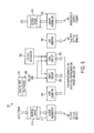
- FIG. 5 is a diagram illustrating a controller 210 according to one embodiment of the invention.
- the controller 210 includes the head and tail pointers 350 and 360 , an ingress queue 510 , a queue segmenter 515 , a data combiner 520 , a write circuit 530 , a read circuit 540 , a egress scheduler 550 , a list creator 560 , an egress queue 570 , and an egress queue assembler 575 .
- the head and tail pointers 350 and 360 are used to point to the head and tail chunks corresponding to the input buffer queues in the input buffer memory 220 according to the linked list 300 illustrate in FIG. 3A .
- the head and tail pointers 350 and 360 are updated each time data from the input buffer queue are burst written to the packet memory 230 .
- the ingress queue 510 buffers the data stream coming from the ingress of the channel on the input data path.
- the ingress queue 510 acts as a temporary storage for the data stream before being loaded into the input buffer memory 220 .
- the queue segmenter 515 slices the data from the ingress queue 510 into blocks of data of fixed size so that they can be transferred to the input buffer queues of the input buffer memory 220 .
- the data combiner 520 combines the chunk data blocks in the input buffer queues to form a contiguous data block to be burst written into the packet memory 230 when a transfer condition occurs such as a queue threshold overflow.
- a transfer condition occurs such as a queue threshold overflow.
- the write circuit 530 performs a burst write of the combined data block into the packet memory 230 .
- the write circuit 530 receives the packet size to determine what transfer mode to be performed. For a long packet, the write circuit 530 writes to the packet memory 230 and then to the output buffer memory 240 . For a short packet, the write circuit 530 writes directly to the output buffer memory 240 bypassing the packet memory 230 .
- the write circuit 530 receives a command signal from the egress scheduler 550 to perform the burst write.
- the read circuit 540 performs a burst read of the combined data block from the packet memory 230 to the output buffer memory 240 . This operation is the expansion operation as explained in FIG. 3C .
- the read circuit 540 receives the packet size to determine what transfer mode to be performed. For a long packet, the read circuit 540 read from the packet memory 230 . For a short packet, the read circuit 540 reads directly from the input buffer memory 220 bypassing the packet memory 230 . In addition, the read circuit 540 receives a command signal from the egress scheduler 550 to perform the burst read.
- the egress scheduler 550 schedules the egress data demand according to network traffic. When there is a demand for data transfer, the egress scheduler 550 generates a command signal to the read circuit 540 to initiate a data transfer to the egress.
- the list creator 560 creates an ordered list of pointers associated with the chunk headers of the chunks that are transferred from the input buffer memory 220 to the packet memory 230 .
- the ordered list of pointers are transferred to the output buffer memory 240 to form a pointer chunk as explained in FIG. 3C .
- the list creator 560 extracts the chunk pointers from the chunks when the chunks are transferred from the input buffer memory 210 to the packet memory 220 .
- the egress queue 570 buffers the data to be sent to the egress of the channel.
- the queue assembler 575 receives data from the output buffer memory 240 and assembles the data into proper format to be loaded into the egress queue 570 .
- FIG. 6 is a diagram illustrating a data transfer 600 for long packets according to one embodiment of the invention.
- the data transfer 600 includes transfer paths 610 , 620 , 630 and 640 , respectively.
- the data transfer for long packets takes place in four basic ordered steps: steps 1 , 2 , 3 , and 4 .
- the steps 1 , 2 , 3 , and 4 correspond to the transfer paths 610 , 620 , 630 , and 640 .
- step 1 data are transferred via the transfer path 610 from the buffer management controller 210 to the input buffer memory 220 .
- the data are organized according to the linked list structure into chunks by the queue segmenter 515 as shown in FIG. 5 . These data chunks are loaded into the input buffer queues 410 1 to 410 K according to the connection identifiers as shown in FIG. 4 .
- incoming data for each network connection may arrive a regular rate at any time.
- the buffer management controller 210 determines the connection identifier associated with the connection and transfers the data to the corresponding input buffer queue in the input buffer memory 220 .
- the amount of data loaded into the input buffer queue is determined to see if the queue threshold has been approached, or if overflow is going to occur.
- the buffer management controller 210 also determines if the packet is long or short so that the appropriate transfer mode can be used for efficient transfer. Since there is some overhead involved in transferring data via the packet memory 230 , it is more efficient to transfer data directly to the output buffer memory 240 for short packets.
- the data in the input buffer queue 220 are transferred to the packet memory 230 and/or the output buffer memory 240 via a transfer path 620 when a transfer condition occurs.
- This transfer condition may be a request for data from the egress scheduler 550 .
- the transfer path 620 includes transfer subpaths 622 and 624 .
- the transfer subpath 622 corresponds to data transfer from the input buffer memory 220 to the packet memory 230 .
- the transfer subpath 624 corresponds to data transfer from the input buffer memory 220 directly to the output buffer memory 240 .
- the data blocks of the chunks in the input buffer queue are combined by the data combiner 520 in the buffer management controller 210 as shown in FIG. 5 .
- the combined data block is then burst written into the packet memory 230 via the transfer subpath 622 when a transfer condition occurs.
- An ordered list of pointers is transferred to the output buffer memory 240 .
- This list contains pointers to the newly created large data chunks stored in the packet memory illustrated in FIG. 3 .
- the head pointer is now updated to point to the chunk pointer of the head chunk now located in the output buffer memory 240 . This step corresponds to the collapse operation as shown in FIG. 3B .
- step 3 the combined data block from the packet memory 230 is burst read to the output buffer memory 240 via transfer path 630 when a transfer condition occurs.
- This transfer condition may be provided by the egress scheduler. Again, this burst read provides efficient data transfer.
- the combined data block is now stored in the output buffer memory 240 according to its connection identifier.
- the individual chunk data blocks are extracted from the combined data block and prepended with the corresponding chunk headers to form a linked list of chunks as originally organized. This step corresponds to the expansion operation as shown in FIG. 3C .
- the data block is transferred to the buffer management controller 210 to be sent to the egress of the channel.
- the data block may be reorganized so that only actual data are sent. Chunk information such as header, size and type specifiers are not needed and removed.
- FIG. 7 is a diagram illustrating a data transfer 700 for short packets according to one embodiment of the invention.
- the data transfer 700 includes transfer paths 710 , 720 , and 730 .
- the data transfer for short packets takes place in three basic ordered steps: steps 1 , 2 , and 3 .
- the steps 1 , 2 , and 3 correspond to the transfer paths 710 , 720 , and 730 , respectively.
- step 1 data are transferred via the transfer path 710 from the buffer management controller 210 to the input buffer memory 220 in much the same way as shown in FIG. 6 .
- the data are transferred to the output buffer memory 240 via the transfer path 720 , bypassing the packet memory 230 when a transfer condition occurs.
- the head pointer is updated to point to the corresponding chunk located in the output buffer memory 240 . Since the packet size is small, the transfer rate can be fast without the need of going through the packet memory 230 .
- step 3 the data are transferred from the output buffer memory 240 to the buffer management controller 210 ( FIG. 1 ) via path 730 .
- This step is similar to the step illustrated in FIG. 6 .
- FIG. 8A is a diagram illustrating a data transfer path 801 to the input buffer memory for long packets according to one embodiment of the invention.
- the data transfer path 801 corresponds to step 1 as shown in FIG. 6 .
- the data organized into a linked list.
- there are four chunks A, B, C, and D ( 812 , 814 , 816 , and 818 ) where chunk A 812 is the head chunk, chunk D 818 is the tail chunk, and chunks C and D, 814 and 816 are linking chunks.
- the header and tail pointers point to the header chunk 812 and 818 , respectively.
- FIG. 8B is a diagram illustrating a data transfer path 802 to the packet memory and the output buffer memory for long packets according to one embodiment of the invention.
- the data transfer path 802 corresponds to step 2 as shown in FIG. 6 .
- Each of the chunks is split into a chunk header and a chunk data block.
- the data combiner 520 in the buffer management controller 210 combines the data blocks to form a large combined data block 810 including the chunk data blocks A and B.
- the list of pointers including chunk pointers a and b is sent to the output buffer memory 240 .
- the head and tail pointers are updated to point to the corresponding chunks now in the output buffer memory 240
- the chunk pointers a and b in the output buffer memory 240 point to the data blocks A and B in the packet memory 230 , respectively.
- the data transfer path 802 corresponds to the collapse operation shown in FIG. 3B .
- FIG. 8C is a diagram illustrating a data transfer path 803 for the data blocks to the output buffer memory for long packets according to one embodiment of the invention.
- the data transfer path 803 corresponds to step 3 as shown in FIG. 6 .
- the combined data block is burst read from the packet memory 230 to the output buffer memory 240 . Since a larger data block is read using the read burst mode, the data transfer can be made more efficient.
- the output buffer memory 240 the combined data blocks are split up to associate with the corresponding chunk pointers. For example, data block A is merged with chunk pointer a.
- the data transfer path 803 corresponds to the expansion operation shown in FIG. 3C .
- FIG. 8D is a diagram illustrating a data transfer path 804 to the controller for long packets according to one embodiment of the invention.
- the data transfer path 804 corresponds to step 4 as shown in FIG. 6 .
- the data blocks A and B are sent from the output buffer memory 240 to the buffer management controller 210 .
- the data blocks are assembled and organized into proper format by the queue assembler 575 before loading into the egress queue 570 as shown in FIG. 5 .
Abstract
Description
Claims (21)
Priority Applications (1)
| Application Number | Priority Date | Filing Date | Title |
|---|---|---|---|
| US11/924,340 US8072996B2 (en) | 1999-09-24 | 2007-10-25 | Multiple-buffer queueing of data packets with high throughput rate |
Applications Claiming Priority (3)
| Application Number | Priority Date | Filing Date | Title |
|---|---|---|---|
| US15609899P | 1999-09-24 | 1999-09-24 | |
| US09/668,407 US7301954B1 (en) | 1999-09-24 | 2000-09-22 | Multiple-buffer queueing of data packets with high throughput rate |
| US11/924,340 US8072996B2 (en) | 1999-09-24 | 2007-10-25 | Multiple-buffer queueing of data packets with high throughput rate |
Related Parent Applications (1)
| Application Number | Title | Priority Date | Filing Date |
|---|---|---|---|
| US09/668,407 Continuation US7301954B1 (en) | 1999-09-24 | 2000-09-22 | Multiple-buffer queueing of data packets with high throughput rate |
Publications (2)
| Publication Number | Publication Date |
|---|---|
| US20080104313A1 US20080104313A1 (en) | 2008-05-01 |
| US8072996B2 true US8072996B2 (en) | 2011-12-06 |
Family
ID=38722008
Family Applications (2)
| Application Number | Title | Priority Date | Filing Date |
|---|---|---|---|
| US09/668,407 Expired - Lifetime US7301954B1 (en) | 1999-09-24 | 2000-09-22 | Multiple-buffer queueing of data packets with high throughput rate |
| US11/924,340 Expired - Fee Related US8072996B2 (en) | 1999-09-24 | 2007-10-25 | Multiple-buffer queueing of data packets with high throughput rate |
Family Applications Before (1)
| Application Number | Title | Priority Date | Filing Date |
|---|---|---|---|
| US09/668,407 Expired - Lifetime US7301954B1 (en) | 1999-09-24 | 2000-09-22 | Multiple-buffer queueing of data packets with high throughput rate |
Country Status (1)
| Country | Link |
|---|---|
| US (2) | US7301954B1 (en) |
Cited By (1)
| Publication number | Priority date | Publication date | Assignee | Title |
|---|---|---|---|---|
| US20100332686A1 (en) * | 2004-04-20 | 2010-12-30 | Creta Kenneth C | Write combining protocol between processors and chipsets |
Families Citing this family (21)
| Publication number | Priority date | Publication date | Assignee | Title |
|---|---|---|---|---|
| US7301954B1 (en) * | 1999-09-24 | 2007-11-27 | United States Of America As Represented By The Secretary Of The Navy | Multiple-buffer queueing of data packets with high throughput rate |
| US7782778B2 (en) * | 2002-12-24 | 2010-08-24 | Samir Satish Sheth | Apparatus and method for fibre channel distance extension embedded within an optical transport system |
| US7656905B2 (en) * | 2002-12-24 | 2010-02-02 | Samir Sheth | Apparatus and method for aggregation and transportation of gigabit ethernet and other packet based data formats |
| EP1684164A1 (en) * | 2005-01-13 | 2006-07-26 | Thomson Licensing | Data transfer system |
| US7836107B2 (en) * | 2007-12-20 | 2010-11-16 | Microsoft Corporation | Disk seek optimized file system |
| US8447901B2 (en) | 2011-02-18 | 2013-05-21 | Ab Initio Technology Llc | Managing buffer conditions through sorting |
| US9003084B2 (en) * | 2011-02-18 | 2015-04-07 | Ab Initio Technology Llc | Sorting |
| US8949487B1 (en) * | 2013-07-29 | 2015-02-03 | Western Digital Technologies, Inc. | Data transmission from data storage device |
| US9712442B2 (en) * | 2013-09-24 | 2017-07-18 | Broadcom Corporation | Efficient memory bandwidth utilization in a network device |
| US9654849B2 (en) * | 2015-05-15 | 2017-05-16 | Huawei Technologies Co., Ltd. | System and method for photonic switching |
| CN106330741B (en) * | 2015-06-15 | 2020-04-24 | 深圳市中兴微电子技术有限公司 | Message transmission method and device |
| US11032257B1 (en) | 2017-12-08 | 2021-06-08 | Rankin Labs, Llc | Method for covertly delivering a packet of data over a network |
| US11861025B1 (en) | 2018-01-08 | 2024-01-02 | Rankin Labs, Llc | System and method for receiving and processing a signal within a TCP/IP protocol stack |
| US11689543B2 (en) | 2018-08-10 | 2023-06-27 | Rankin Labs, Llc | System and method for detecting transmission of a covert payload of data |
| WO2020132173A1 (en) | 2018-12-19 | 2020-06-25 | John Rankin | Hidden electronic file systems |
| US11108671B2 (en) | 2019-01-21 | 2021-08-31 | Rankin Labs, Llc | Systems and methods for processing network traffic using dynamic memory |
| US11487674B2 (en) | 2019-04-17 | 2022-11-01 | Rankin Labs, Llc | Virtual memory pool within a network which is accessible from multiple platforms |
| US11729184B2 (en) | 2019-05-28 | 2023-08-15 | Rankin Labs, Llc | Detecting covertly stored payloads of data within a network |
| WO2020243244A1 (en) | 2019-05-28 | 2020-12-03 | John Rankin | Supporting a virtual memory area at a remote computing machine |
| US11055166B2 (en) | 2019-05-28 | 2021-07-06 | Rankin Labs, Llc | Covertly storing a payload of data within a network |
| WO2021127320A1 (en) | 2019-12-18 | 2021-06-24 | John Rankin | Distribution of data over a network with interconnected rings |
Citations (27)
| Publication number | Priority date | Publication date | Assignee | Title |
|---|---|---|---|---|
| US5541922A (en) * | 1992-10-05 | 1996-07-30 | Nokia Telecommunications Oy | Method for assigning priority to traffic between local area networks interconnected via a backbone network |
| US5546391A (en) | 1993-03-04 | 1996-08-13 | International Business Machines Corporation | Central shared queue based time multiplexed packet switch with deadlock avoidance |
| US5875189A (en) | 1994-09-14 | 1999-02-23 | Fore Systems, Inc. | Method and apparatus for multicast of ATM cells |
| US5936956A (en) | 1995-08-11 | 1999-08-10 | Fujitsu Limited | Data receiving devices |
| US6011775A (en) | 1997-04-04 | 2000-01-04 | At & T Corp. | Method and apparatus for integrated traffic shaping in a packet-switched network |
| US6088745A (en) | 1998-03-17 | 2000-07-11 | Xylan Corporation | Logical output queues linking buffers allocated using free lists of pointer groups of multiple contiguous address space |
| US6128306A (en) | 1996-08-30 | 2000-10-03 | Sgs-Thomson Microelectronics Limited | Cell queue formation in an ATM switch |
| US20010009551A1 (en) | 1997-03-19 | 2001-07-26 | Norihiko Moriwaki | ATM switch |
| US6295295B1 (en) | 1995-11-27 | 2001-09-25 | Telefonaktiebolaget Lm Ericsson | Scheduler for an information packet switch |
| US6310884B1 (en) | 1998-05-21 | 2001-10-30 | Lsi Logic Corporation | Data transfer method and apparatus that allocate storage based upon a received relative offset |
| US6320865B1 (en) | 1996-06-10 | 2001-11-20 | University Of Maryland At College Park | Method and apparatus for implementing time-based data flow control and network implementation thereof |
| US6349089B1 (en) | 1997-11-24 | 2002-02-19 | Riverstone Networks, Inc. | Flexible scheduler in an asynchronous transfer mode (ATM) switch |
| US6366984B1 (en) | 1999-05-11 | 2002-04-02 | Intel Corporation | Write combining buffer that supports snoop request |
| US6377583B1 (en) | 1996-06-27 | 2002-04-23 | Xerox Corporation | Rate shaping in per-flow output queued routing mechanisms for unspecified bit rate service |
| US6401147B1 (en) | 1999-05-24 | 2002-06-04 | Advanced Micro Devices, Inc. | Split-queue architecture with a first queue area and a second queue area and queue overflow area having a trickle mode and an overflow mode based on prescribed threshold values |
| US6496478B1 (en) | 1999-04-10 | 2002-12-17 | 3Com Corporation | Method and apparatus for controlling traffic queues in network switches |
| US6523060B1 (en) | 1995-04-07 | 2003-02-18 | Cisco Technology, Inc. | Method and apparatus for the management of queue pointers by multiple processors in a digital communications network |
| US6539024B1 (en) | 1999-03-26 | 2003-03-25 | Alcatel Canada Inc. | Method and apparatus for data buffer management in a communications switch |
| US6542502B1 (en) | 1996-01-26 | 2003-04-01 | International Business Machines Corporation | Multicasting using a wormhole routing switching element |
| US6556579B1 (en) | 1999-09-21 | 2003-04-29 | 3Com Corporation | Method and apparatus for detecting duplicate buffers in a descriptor based multi-port queue |
| US6570876B1 (en) | 1998-04-01 | 2003-05-27 | Hitachi, Ltd. | Packet switch and switching method for switching variable length packets |
| US6594270B1 (en) | 1999-04-21 | 2003-07-15 | 3Com Corporation | Ageing of data packets using queue pointers |
| US6628652B1 (en) | 1998-09-18 | 2003-09-30 | Lucent Technologies Inc. | Flexible telecommunications switching network |
| US6631484B1 (en) * | 1998-03-31 | 2003-10-07 | Lsi Logic Corporation | System for packet communication where received packet is stored either in a FIFO or in buffer storage based on size of received packet |
| US6721796B1 (en) | 1999-07-22 | 2004-04-13 | Cisco Technology, Inc. | Hierarchical dynamic buffer management system and method |
| US6724767B1 (en) * | 1998-06-27 | 2004-04-20 | Intel Corporation | Two-dimensional queuing/de-queuing methods and systems for implementing the same |
| US7301954B1 (en) * | 1999-09-24 | 2007-11-27 | United States Of America As Represented By The Secretary Of The Navy | Multiple-buffer queueing of data packets with high throughput rate |
-
2000
- 2000-09-22 US US09/668,407 patent/US7301954B1/en not_active Expired - Lifetime
-
2007
- 2007-10-25 US US11/924,340 patent/US8072996B2/en not_active Expired - Fee Related
Patent Citations (28)
| Publication number | Priority date | Publication date | Assignee | Title |
|---|---|---|---|---|
| US5541922A (en) * | 1992-10-05 | 1996-07-30 | Nokia Telecommunications Oy | Method for assigning priority to traffic between local area networks interconnected via a backbone network |
| US5546391A (en) | 1993-03-04 | 1996-08-13 | International Business Machines Corporation | Central shared queue based time multiplexed packet switch with deadlock avoidance |
| US5875189A (en) | 1994-09-14 | 1999-02-23 | Fore Systems, Inc. | Method and apparatus for multicast of ATM cells |
| US6523060B1 (en) | 1995-04-07 | 2003-02-18 | Cisco Technology, Inc. | Method and apparatus for the management of queue pointers by multiple processors in a digital communications network |
| US5936956A (en) | 1995-08-11 | 1999-08-10 | Fujitsu Limited | Data receiving devices |
| US6295295B1 (en) | 1995-11-27 | 2001-09-25 | Telefonaktiebolaget Lm Ericsson | Scheduler for an information packet switch |
| US6542502B1 (en) | 1996-01-26 | 2003-04-01 | International Business Machines Corporation | Multicasting using a wormhole routing switching element |
| US6320865B1 (en) | 1996-06-10 | 2001-11-20 | University Of Maryland At College Park | Method and apparatus for implementing time-based data flow control and network implementation thereof |
| US6377583B1 (en) | 1996-06-27 | 2002-04-23 | Xerox Corporation | Rate shaping in per-flow output queued routing mechanisms for unspecified bit rate service |
| US6128306A (en) | 1996-08-30 | 2000-10-03 | Sgs-Thomson Microelectronics Limited | Cell queue formation in an ATM switch |
| US20010009551A1 (en) | 1997-03-19 | 2001-07-26 | Norihiko Moriwaki | ATM switch |
| US6011775A (en) | 1997-04-04 | 2000-01-04 | At & T Corp. | Method and apparatus for integrated traffic shaping in a packet-switched network |
| US6396834B1 (en) | 1997-11-24 | 2002-05-28 | Riverstone Networks, Inc. | Flexible scheduler in an asynchronous transfer mode (ATM) switch |
| US6349089B1 (en) | 1997-11-24 | 2002-02-19 | Riverstone Networks, Inc. | Flexible scheduler in an asynchronous transfer mode (ATM) switch |
| US6088745A (en) | 1998-03-17 | 2000-07-11 | Xylan Corporation | Logical output queues linking buffers allocated using free lists of pointer groups of multiple contiguous address space |
| US6631484B1 (en) * | 1998-03-31 | 2003-10-07 | Lsi Logic Corporation | System for packet communication where received packet is stored either in a FIFO or in buffer storage based on size of received packet |
| US6570876B1 (en) | 1998-04-01 | 2003-05-27 | Hitachi, Ltd. | Packet switch and switching method for switching variable length packets |
| US6310884B1 (en) | 1998-05-21 | 2001-10-30 | Lsi Logic Corporation | Data transfer method and apparatus that allocate storage based upon a received relative offset |
| US6724767B1 (en) * | 1998-06-27 | 2004-04-20 | Intel Corporation | Two-dimensional queuing/de-queuing methods and systems for implementing the same |
| US6628652B1 (en) | 1998-09-18 | 2003-09-30 | Lucent Technologies Inc. | Flexible telecommunications switching network |
| US6539024B1 (en) | 1999-03-26 | 2003-03-25 | Alcatel Canada Inc. | Method and apparatus for data buffer management in a communications switch |
| US6496478B1 (en) | 1999-04-10 | 2002-12-17 | 3Com Corporation | Method and apparatus for controlling traffic queues in network switches |
| US6594270B1 (en) | 1999-04-21 | 2003-07-15 | 3Com Corporation | Ageing of data packets using queue pointers |
| US6366984B1 (en) | 1999-05-11 | 2002-04-02 | Intel Corporation | Write combining buffer that supports snoop request |
| US6401147B1 (en) | 1999-05-24 | 2002-06-04 | Advanced Micro Devices, Inc. | Split-queue architecture with a first queue area and a second queue area and queue overflow area having a trickle mode and an overflow mode based on prescribed threshold values |
| US6721796B1 (en) | 1999-07-22 | 2004-04-13 | Cisco Technology, Inc. | Hierarchical dynamic buffer management system and method |
| US6556579B1 (en) | 1999-09-21 | 2003-04-29 | 3Com Corporation | Method and apparatus for detecting duplicate buffers in a descriptor based multi-port queue |
| US7301954B1 (en) * | 1999-09-24 | 2007-11-27 | United States Of America As Represented By The Secretary Of The Navy | Multiple-buffer queueing of data packets with high throughput rate |
Cited By (2)
| Publication number | Priority date | Publication date | Assignee | Title |
|---|---|---|---|---|
| US20100332686A1 (en) * | 2004-04-20 | 2010-12-30 | Creta Kenneth C | Write combining protocol between processors and chipsets |
| US8412855B2 (en) * | 2004-04-20 | 2013-04-02 | Intel Corporation | Write combining protocol between processors and chipsets |
Also Published As
| Publication number | Publication date |
|---|---|
| US7301954B1 (en) | 2007-11-27 |
| US20080104313A1 (en) | 2008-05-01 |
Similar Documents
| Publication | Publication Date | Title |
|---|---|---|
| US8072996B2 (en) | Multiple-buffer queueing of data packets with high throughput rate | |
| US5420858A (en) | Method and apparatus for communications from a non-ATM communication medium to an ATM communication medium | |
| US5459723A (en) | Packet management device for fast-packet network | |
| US7400638B2 (en) | Apparatus and methods for managing packets in a broadband data stream | |
| US6523060B1 (en) | Method and apparatus for the management of queue pointers by multiple processors in a digital communications network | |
| EP0459752B1 (en) | Network adapter using buffers and multiple descriptor rings | |
| US9276835B2 (en) | Packet segmentation with different segment sizes for a switch fabric | |
| US7411968B2 (en) | Two-dimensional queuing/de-queuing methods and systems for implementing the same | |
| CA2134017C (en) | Network bridge | |
| US20050265357A1 (en) | Memory caching | |
| US7606151B2 (en) | Power reduction in switch architectures | |
| JPH09224042A (en) | Device and method for packeting and segmenting mpeg packet | |
| US7675908B2 (en) | Parallel channel architecture | |
| US20050138238A1 (en) | Flow control interface | |
| US7272675B1 (en) | First-in-first-out (FIFO) memory for buffering packet fragments through use of read and write pointers incremented by a unit access and a fraction of the unit access | |
| US5940404A (en) | Method and apparatus for enhanced scatter mode allowing user data to be page aligned | |
| US6622183B1 (en) | Data transmission buffer having frame counter feedback for re-transmitting aborted data frames | |
| US7379467B1 (en) | Scheduling store-forwarding of back-to-back multi-channel packet fragments | |
| EP1508225B1 (en) | Method for data storage in external and on-chip memory in a packet switch | |
| US5903774A (en) | External network network interface device without interim storage connected to high-speed serial bus with low latency and high transmission rate | |
| JPH11234306A (en) | Data transferring device | |
| US20050243605A1 (en) | Apparatus and method for transmitting constant bit rate data cells, controlling transmission of data cells to prevent head data cells from being sent out through the continuous slots of the transmission cycle | |
| EP1326475A1 (en) | Method and apparatus using multiple packet reassembler and memories for performing multiple functions | |
| US7006509B1 (en) | Method and system for graceful slowlink deletion and subsequent fast link addition in an IMA group | |
| JPH10327175A (en) | Switch and switching method |
Legal Events
| Date | Code | Title | Description |
|---|---|---|---|
| AS | Assignment |
Owner name: GOVERNMENT OF THE UNITED STATES, AS REPRESENTED BY Free format text: ASSIGNMENT OF ASSIGNORS INTEREST;ASSIGNOR:ACORN NETWORKS, INC.;REEL/FRAME:020684/0808 Effective date: 20030826 Owner name: ACORN NETWORKS, INC., VIRGINIA Free format text: ASSIGNMENT OF ASSIGNORS INTEREST;ASSIGNOR:CHU, TAM-ANH;REEL/FRAME:020684/0422 Effective date: 20000919 |
|
| ZAAA | Notice of allowance and fees due |
Free format text: ORIGINAL CODE: NOA |
|
| ZAAB | Notice of allowance mailed |
Free format text: ORIGINAL CODE: MN/=. |
|
| ZAAA | Notice of allowance and fees due |
Free format text: ORIGINAL CODE: NOA |
|
| STCF | Information on status: patent grant |
Free format text: PATENTED CASE |
|
| FPAY | Fee payment |
Year of fee payment: 4 |
|
| MAFP | Maintenance fee payment |
Free format text: PAYMENT OF MAINTENANCE FEE, 8TH YEAR, LARGE ENTITY (ORIGINAL EVENT CODE: M1552); ENTITY STATUS OF PATENT OWNER: LARGE ENTITY Year of fee payment: 8 |
|
| FEPP | Fee payment procedure |
Free format text: MAINTENANCE FEE REMINDER MAILED (ORIGINAL EVENT CODE: REM.); ENTITY STATUS OF PATENT OWNER: LARGE ENTITY |
|
| LAPS | Lapse for failure to pay maintenance fees |
Free format text: PATENT EXPIRED FOR FAILURE TO PAY MAINTENANCE FEES (ORIGINAL EVENT CODE: EXP.); ENTITY STATUS OF PATENT OWNER: LARGE ENTITY |
|
| STCH | Information on status: patent discontinuation |
Free format text: PATENT EXPIRED DUE TO NONPAYMENT OF MAINTENANCE FEES UNDER 37 CFR 1.362 |
|
| FP | Lapsed due to failure to pay maintenance fee |
Effective date: 20231206 |