US8070341B2 - Light pipe with uniformly lit appearance - Google Patents
Light pipe with uniformly lit appearance Download PDFInfo
- Publication number
- US8070341B2 US8070341B2 US12/338,187 US33818708A US8070341B2 US 8070341 B2 US8070341 B2 US 8070341B2 US 33818708 A US33818708 A US 33818708A US 8070341 B2 US8070341 B2 US 8070341B2
- Authority
- US
- United States
- Prior art keywords
- light
- light pipe
- reflective elements
- light rays
- pipe
- Prior art date
- Legal status (The legal status is an assumption and is not a legal conclusion. Google has not performed a legal analysis and makes no representation as to the accuracy of the status listed.)
- Active, expires
Links
Images


Classifications
-
- G—PHYSICS
- G02—OPTICS
- G02B—OPTICAL ELEMENTS, SYSTEMS OR APPARATUS
- G02B6/00—Light guides; Structural details of arrangements comprising light guides and other optical elements, e.g. couplings
- G02B6/0001—Light guides; Structural details of arrangements comprising light guides and other optical elements, e.g. couplings specially adapted for lighting devices or systems
- G02B6/0005—Light guides; Structural details of arrangements comprising light guides and other optical elements, e.g. couplings specially adapted for lighting devices or systems the light guides being of the fibre type
- G02B6/001—Light guides; Structural details of arrangements comprising light guides and other optical elements, e.g. couplings specially adapted for lighting devices or systems the light guides being of the fibre type the light being emitted along at least a portion of the lateral surface of the fibre
-
- G—PHYSICS
- G02—OPTICS
- G02B—OPTICAL ELEMENTS, SYSTEMS OR APPARATUS
- G02B6/00—Light guides; Structural details of arrangements comprising light guides and other optical elements, e.g. couplings
- G02B6/24—Coupling light guides
- G02B6/42—Coupling light guides with opto-electronic elements
- G02B6/4298—Coupling light guides with opto-electronic elements coupling with non-coherent light sources and/or radiation detectors, e.g. lamps, incandescent bulbs, scintillation chambers
-
- G—PHYSICS
- G02—OPTICS
- G02B—OPTICAL ELEMENTS, SYSTEMS OR APPARATUS
- G02B6/00—Light guides; Structural details of arrangements comprising light guides and other optical elements, e.g. couplings
- G02B6/0001—Light guides; Structural details of arrangements comprising light guides and other optical elements, e.g. couplings specially adapted for lighting devices or systems
- G02B6/0011—Light guides; Structural details of arrangements comprising light guides and other optical elements, e.g. couplings specially adapted for lighting devices or systems the light guides being planar or of plate-like form
- G02B6/0033—Means for improving the coupling-out of light from the light guide
- G02B6/0035—Means for improving the coupling-out of light from the light guide provided on the surface of the light guide or in the bulk of it
- G02B6/0038—Linear indentations or grooves, e.g. arc-shaped grooves or meandering grooves, extending over the full length or width of the light guide
-
- G—PHYSICS
- G02—OPTICS
- G02B—OPTICAL ELEMENTS, SYSTEMS OR APPARATUS
- G02B6/00—Light guides; Structural details of arrangements comprising light guides and other optical elements, e.g. couplings
- G02B6/0001—Light guides; Structural details of arrangements comprising light guides and other optical elements, e.g. couplings specially adapted for lighting devices or systems
- G02B6/0011—Light guides; Structural details of arrangements comprising light guides and other optical elements, e.g. couplings specially adapted for lighting devices or systems the light guides being planar or of plate-like form
- G02B6/0033—Means for improving the coupling-out of light from the light guide
- G02B6/005—Means for improving the coupling-out of light from the light guide provided by one optical element, or plurality thereof, placed on the light output side of the light guide
- G02B6/0055—Reflecting element, sheet or layer
-
- G—PHYSICS
- G02—OPTICS
- G02B—OPTICAL ELEMENTS, SYSTEMS OR APPARATUS
- G02B6/00—Light guides; Structural details of arrangements comprising light guides and other optical elements, e.g. couplings
- G02B6/0001—Light guides; Structural details of arrangements comprising light guides and other optical elements, e.g. couplings specially adapted for lighting devices or systems
- G02B6/0011—Light guides; Structural details of arrangements comprising light guides and other optical elements, e.g. couplings specially adapted for lighting devices or systems the light guides being planar or of plate-like form
- G02B6/0033—Means for improving the coupling-out of light from the light guide
- G02B6/0058—Means for improving the coupling-out of light from the light guide varying in density, size, shape or depth along the light guide
- G02B6/0061—Means for improving the coupling-out of light from the light guide varying in density, size, shape or depth along the light guide to provide homogeneous light output intensity
Definitions
- the invention relates to lighting. More particularly, the invention is directed to a light pipe and a lighting system for providing a substantially uniform brightness along a length of the light pipe.
- Non-functional decorative light pipes are not commonly used in automotive applications.
- functional light pipes are optimized to produce a specific beam pattern to meet photometric requirements of functions such as parking lamp or tail Lamp, for example. The functional optimization typically overrides any consideration of uniform lit appearance of the light pipe.
- the new trend in automotive lighting is to add non-functional light pipes for vehicle aesthetics.
- ring-shaped light pipes inherently offer a uniform lit appearance
- long straight or curved light pipe designs are very challenging to create the uniform lit appearance throughout an entire length of the light pipe, especially when a light source is mounted at only one end of the light pipe.
- the lit appearance of the light pipe is typically very bright in the region nearest the light source, and dimmer towards the other end.
- Such noticeably varying brightness along the length of the pipe at any viewing angle is preferably avoided to provide an acceptable appearance for the light pipe, since the sole aim of the light pipe is illumination styling and not an optical function.
- a light system including a light pipe wherein the light system provides a substantially uniform lit appearance along a length of the light pipe, while minimizing “hot spots” and noticeably varying brightness at light-coupling ends and curved portions of the light pipe.
- a light system including a light pipe wherein the light system provides a substantially uniform lit appearance along a length of the light pipe, while minimizing “hot spots” and noticeably varying brightness at light-coupling ends and curved portions of the light pipe, has surprisingly been discovered.
- a light pipe having substantially uniform brightness along a length of the light pipe comprises: a first end for receiving a plurality of light rays; a reflective portion for directing the received light rays in a pre-determined internal light pattern, wherein the reflective portion includes a plurality of reflective elements; and an emitting portion for emitting the light rays in a pre-determined light distribution pattern.
- a light pipe having substantially uniform brightness along a length of the light pipe comprises: a first end for receiving a plurality of light rays; a reflective portion for directing the received light rays in a pre-determined internal light pattern, wherein the reflective portion includes a plurality of reflective elements, each of the reflective elements forming a protrusion; and an emitting portion for emitting the light rays in a pre-determined light distribution pattern.
- a lighting system comprises: a light source for emitting a plurality of light rays; a light pipe including: a first end for receiving the light rays; a reflective portion for directing the received light rays in a pre-determined internal light pattern, wherein the reflective portion includes a plurality of reflective elements; and an emitting portion for emitting the light rays in a pre-determined light distribution pattern; and an optics element for directing the light rays into the first end of the light pipe.
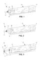
- FIG. 1 is a fragmentary perspective view of a lighting system according to an embodiment of the present invention
- FIG. 2 is a fragmentary perspective view of a lighting system according to another embodiment of the present invention.
- FIG. 3 is a fragmentary perspective view of a lighting system according to another embodiment of the present invention.
- FIG. 4 is a cross sectional view of a light pipe according to an embodiment of the present invention.
- FIG. 5 is a fragmentary bottom elevational view of the light pipe of FIG. 4 ;
- FIG. 6 is a bottom perspective view of a light pipe according to another embodiment of the present invention, shown in a straight formation;
- FIG. 7 is a fragmentary side elevational view of the light pipe of FIG. 6 ;
- FIG. 8 is a fragmentary perspective view of the light pipe of FIG. 6 , shown in a curved formation.
- FIG. 1 illustrates a lighting system 10 according to an embodiment of the present invention.
- the lighting system 10 includes a light source 12 , an optics element 14 , and a light pipe 16 . It is understood that the lighting system 10 may include additional components and features for securing the lighting system 10 to a vehicle, for example. Other components and features may be included, as desired.
- the light source 12 illustrated is a light emitting diode (LED). Any LED, now known or later developed, may be used, as desired. However, other light sources such as bulbs may be used, as desired. As shown, a single light source 12 is disposed adjacent a first end 18 of the light pipe 16 . It is understood that, in certain embodiments, an additional light source 12 may be disposed at a second end 19 of the light pipe 16 . As a non-limiting example, a plurality of light rays 20 emitted from the light source 12 may propagate directly into at least one of the first end 18 and the second end 19 of the light pipe 12 . However, it is understood that the light rays 20 emitted from the light source 12 may be directed and collimated by the optics element 14 before entering the light pipe 12 .
- LED light emitting diode
- the optics element 14 may be any optical device or system for at least one of directing, collimating, and refracting light rays. As such, the optics element 14 minimizes a “hot area” that typically appears near the in-coupling end of the light pipe 16 , shown as the first end 18 . In certain embodiments, the optics element 14 substantially collimates the light rays 20 and balances the distribution of the light rays 20 entering the light pipe 16 .
- the optics element 14 is a partial area lens disposed adjacent the first end 18 of the light pipe 16 , wherein at least a portion of the first end 18 is substantially planar.
- the partial area lens is at least one of a convex lens and a near field lens. It is understood that the optics element 14 may have pre-determined characteristics for directing and collimating the light rays 20 in a pre-determined light pattern.
- the light pipe 16 illustrated is formed from a substantially transparent and solid plastic or glass. However, other materials may be used, as desired. It is understood that the light pipe 16 may be formed from a flexible material. It is further understood that the light pipe 16 may be straight or curved. As such, the light pipe 16 is adapted to receive the light rays 20 from at least one of the first end 18 and the second end 19 . In certain embodiments, the light pipe 16 has a length greater than 400 millimeters. However, the light pipe 16 may have any length, as desired.
- FIG. 2 illustrates a lighting system 10 ′ according to another embodiment of the present invention similar to the lighting system 10 of FIG. 1 , except as described below. Structure repeated from the description of FIG. 1 includes the same reference numeral. Variations of structure shown in FIG. 1 include the same reference numeral and a prime (′) symbol.
- the optics element 14 ′ is a full area lens disposed adjacent the first end 18 of the light pipe 16 , wherein the first end 18 is substantially covered by the full area lens.
- the full area lens is at least one of a convex lens and a near field lens. It is understood that the optics element 14 ′ may have pre-determined characteristics for directing and collimating light rays in a pre-determined light pattern.
- FIG. 3 illustrates a lighting system 10 ′′ according to yet another embodiment of the present invention similar to the lighting system 10 of FIG. 1 , except as described below. Structure repeated from the description of FIG. 1 includes the same reference numeral. Variations of structure shown in FIG. 1 include the same reference numeral and a double-prime (′′) symbol.
- the optics element 14 ′′ is a concave reflecting device for directing and substantially collimating the light rays into the first end 18 of the light pipe 16 . It is understood that the optics element 14 ′′ may have pre-determined characteristics for directing and collimating light rays in a pre-determined light pattern. Other lenses and light directing devices may be used, as desired.
- FIGS. 4 and 5 illustrate the light pipe 16 according to another embodiment of the present invention.
- the light pipe 16 includes an emitting portion 22 and a reflective portion 24 .
- the emitting portion 22 is shown having a curved surface for directing the light rays emitted from the light pipe 16 in a pre-determined light pattern.
- the emitting portion 22 may have any shape and size, as desired.
- the emitting portion 22 includes a light control component 23 .
- the light control component 23 provides a means for bending and directing the light rays 20 into a desired light pattern or distribution.
- the light control component 23 may be a coating, a film, a paint, or an optics element.
- the reflective portion 24 includes a plurality of reflective elements 26 to reflect the light rays 20 in a pre-determined light pattern so the light rays 20 exit the light pipe 16 through the emitting portion 22 .
- the reflective elements 26 may be formed from at least one of a texture, an embedded material, and paint for diffusing and reflecting the light rays 20 .
- material characteristics such as texture density and reflectivity may be varied to achieve a substantial uniformity in the perceived brightness of the light emitted from the light pipe 16 along a length thereof.
- the reflective elements 26 are spaced apart in a pre-determined spacing pattern. Specifically, a spacing of the reflective elements 26 varies such that the spacing between two of the reflective elements 26 at a light entrance end is wider than the spacing between two of the reflective elements 26 at an opposite end of the light pipe 16 . Additionally, a width of the reflective elements 26 measured in a direction lateral to a longitudinal axis of the light pipe 16 varies such that the width of one of the reflective elements 26 at a light entrance end is narrower than the width of one of the reflective elements 26 at an opposite end of the light pipe 16 . It is understood that any spacing pattern may be used. It is further understood that each of the reflecting elements 26 may have any width and spacing including a constant width or spacing.
- FIGS. 6-8 illustrate a light pipe 16 ′ according to another embodiment of the invention similar to the lighting system 10 of FIGS. 4 and 5 , except as described below. Structure repeated from the description of FIGS. 4 and 5 includes the same reference numeral. Variations of structure shown in FIGS. 4 and 5 include the same reference numeral and a prime (′) symbol.
- each of the reflective elements 26 ′ is a protrusion having a substantially arcuate inner surface 27 for reflecting and directing the light rays 20 in a desired internal light pattern.
- each of the reflective elements 26 ′ form a semi- or partially-circular protrusion or “tooth” protruding outside the light pipe material.
- the shape and size of the reflective elements 26 ′ may be modified to obtain a desired lit appearance at various viewing angles relative to the emitting portion 22 of the light pipe 16 ′ such as a uniformly lit appearance.
- a depth of each of the reflective elements 26 ′ is progressively increased and the spacing between two neighboring reflective elements 26 ′ (pitch) is progressively decreased from an end where light enters the light pipe 16 to an opposite end.
- a width of each of the reflective elements 26 ′ along the circumference of the light pipe 16 may also vary. As a non-limiting example, the width of each of the reflective elements 26 ′ may be narrower at the light entrance end and wider at the opposite end.
- the light source 12 emits the light rays 20 .
- the optics element 14 , 14 ′ directs the light rays 20 into the light pipe 16 , 16 ′.
- the light rays 20 may enter the light pipe 16 , 16 ′ directly.
- the light rays 20 travel through the light pipe 16 , 16 ′ by the principle of total internal reflection.
- the reflective elements 26 , 26 ′ direct the light rays 20 in the pre-determined internal lighting pattern such that the light rays 20 propagate through the length of the light pipe 16 , 16 ′, while exiting only through the emitting portion 22 of the light pipe 16 , 16 ′.
- each of the reflective elements 26 , 26 ′ reflects the light rays 20 based upon a shape, a size, a curvature, and a surface area of the inner surface 27 . It is further understood that a spacing of each of the reflective elements 26 , 26 ′ relative to another of the reflective elements 26 , 26 ′ regulates the internal reflection of the light rays 20 along the length of the light pipe 16 , 16 ′.
- the light system 10 , 10 ′ including the light pipe 16 , 16 ′ of the present invention provides a substantially uniform lit appearance along a length of the light pipe 16 , 16 ′ while minimizing “hot spots” and noticeably varying brightness at light-coupling ends and curved portions of the light pipe 16 , 16 ′.
- the light system 10 , 10 ′ minimizes a package size and minimizes a complexity of thermal management in certain embodiments by using a single light source 12 .
- the invention focuses on automotive applications, this technology is also be applicable for other applications in other industries such as advertising, indications, signs, and so on.
Landscapes
- Physics & Mathematics (AREA)
- General Physics & Mathematics (AREA)
- Optics & Photonics (AREA)
- Non-Portable Lighting Devices Or Systems Thereof (AREA)
- Planar Illumination Modules (AREA)
Abstract
Description
Claims (8)
Priority Applications (2)
| Application Number | Priority Date | Filing Date | Title |
|---|---|---|---|
| US12/338,187 US8070341B2 (en) | 2008-12-18 | 2008-12-18 | Light pipe with uniformly lit appearance |
| DE102009054543A DE102009054543A1 (en) | 2008-12-18 | 2009-12-11 | Light tube with uniformly illuminated appearance |
Applications Claiming Priority (1)
| Application Number | Priority Date | Filing Date | Title |
|---|---|---|---|
| US12/338,187 US8070341B2 (en) | 2008-12-18 | 2008-12-18 | Light pipe with uniformly lit appearance |
Publications (2)
| Publication Number | Publication Date |
|---|---|
| US20100157619A1 US20100157619A1 (en) | 2010-06-24 |
| US8070341B2 true US8070341B2 (en) | 2011-12-06 |
Family
ID=42265789
Family Applications (1)
| Application Number | Title | Priority Date | Filing Date |
|---|---|---|---|
| US12/338,187 Active 2029-07-27 US8070341B2 (en) | 2008-12-18 | 2008-12-18 | Light pipe with uniformly lit appearance |
Country Status (2)
| Country | Link |
|---|---|
| US (1) | US8070341B2 (en) |
| DE (1) | DE102009054543A1 (en) |
Cited By (9)
| Publication number | Priority date | Publication date | Assignee | Title |
|---|---|---|---|---|
| US20100284182A1 (en) * | 2009-05-11 | 2010-11-11 | Pan Wen-Shin | Led illumination device and led illumination module for generating uniform stripped light source |
| US20110090713A1 (en) * | 2008-07-08 | 2011-04-21 | Helio Optoelectronics Corporation | Flexible backlight module |
| US20110228549A1 (en) * | 2010-03-16 | 2011-09-22 | Toyota Motor Engineering & Manufacturing North America, Inc. | Headlamp bulb type light pipe |
| US20140169025A1 (en) * | 2012-12-15 | 2014-06-19 | Lumenetix, Inc. | System and method for mixing and guiding light emitted from light emitting diodes to a light pipe for emission in a linear configuration |
| US8870428B2 (en) * | 2012-06-20 | 2014-10-28 | Energy Focus, Inc. | Elongated LED lighting arrangement |
| US9188726B2 (en) | 2011-10-28 | 2015-11-17 | Bayerische Motoren Werke Aktiengesellschaft | Lighting device for a motor vehicle |
| US20170367273A1 (en) * | 2016-06-24 | 2017-12-28 | Ryan Bylsma | Devices and Methods for Illuminating Plants |
| US20180313993A1 (en) * | 2015-05-08 | 2018-11-01 | 3M Innovative Properties Company | Lightguide |
| US11820284B2 (en) * | 2018-09-05 | 2023-11-21 | Ts Tech Co., Ltd. | Vehicle illumination device and vehicle door |
Families Citing this family (21)
| Publication number | Priority date | Publication date | Assignee | Title |
|---|---|---|---|---|
| JP2012174641A (en) * | 2011-02-24 | 2012-09-10 | Koito Mfg Co Ltd | Lamp for vehicle |
| TW201239423A (en) * | 2011-03-28 | 2012-10-01 | Chimei Innolux Corp | Light guide assembly and touch panel |
| TW201326675A (en) * | 2011-12-19 | 2013-07-01 | Dongguan Masstop Liquid Crystal Display Co Ltd | Lighting fixture |
| US8752986B2 (en) | 2012-02-21 | 2014-06-17 | Toyota Motor Engineering & Manufacturing North America, Inc. | Vehicle lamp assembly having uniform lit appearance |
| US9805630B2 (en) * | 2012-03-09 | 2017-10-31 | Apple Inc. | Light guide structures for display backlights |
| DE102012007541B4 (en) * | 2012-04-14 | 2022-10-13 | Volkswagen Aktiengesellschaft | Light guide for a vehicle light and vehicle light with a light guide |
| DE102012007542B4 (en) * | 2012-04-14 | 2022-10-13 | Volkswagen Aktiengesellschaft | Vehicle light with a light guide arrangement |
| WO2014036370A1 (en) * | 2012-08-31 | 2014-03-06 | Idd Aerospace Corporation | Side emitting optical apparatus and method for possible use in an aircraft |
| DE102012108855A1 (en) | 2012-09-20 | 2014-03-20 | Hella Kgaa Hueck & Co. | Optical fiber for vehicles |
| KR101927157B1 (en) | 2012-10-15 | 2018-12-10 | 현대자동차 주식회사 | Lighting device for motor vehicle |
| US20140268865A1 (en) * | 2013-03-15 | 2014-09-18 | Idd Aerospace Corporation | Side emitting optical apparatus and method for possible use in an aircraft |
| TWI500985B (en) * | 2013-07-23 | 2015-09-21 | Cheng Tao Lee | Light guide |
| KR101500387B1 (en) * | 2013-09-12 | 2015-03-09 | 기아자동차 주식회사 | Head light module |
| US10330845B2 (en) * | 2014-09-24 | 2019-06-25 | Rebo Lighting & Electronics, Llc | Waveguide for controlled light distribution |
| JP6490432B2 (en) * | 2015-01-26 | 2019-03-27 | スタンレー電気株式会社 | Lighting device |
| US10060590B2 (en) * | 2015-10-05 | 2018-08-28 | Fu An Industrial Co., Ltd. | Light ring structure for vehicle lamp |
| US10690837B2 (en) | 2016-06-21 | 2020-06-23 | Apple Inc. | Backlist displays with bent light guide layers |
| FR3068485B1 (en) * | 2017-06-30 | 2019-11-29 | Valeo Vision | LASER-SHAPED OPTICAL GUIDE |
| JP7328257B2 (en) * | 2018-05-21 | 2023-08-16 | 日東電工株式会社 | Improved light distribution element |
| WO2020005320A1 (en) * | 2018-06-30 | 2020-01-02 | Fusao Ishii | An augmented reality (ar) display |
| WO2022024824A1 (en) * | 2020-07-28 | 2022-02-03 | 日東電工株式会社 | Lighting device |
Citations (28)
| Publication number | Priority date | Publication date | Assignee | Title |
|---|---|---|---|---|
| US4422719A (en) | 1981-05-07 | 1983-12-27 | Space-Lyte International, Inc. | Optical distribution system including light guide |
| US4466697A (en) | 1981-11-12 | 1984-08-21 | Maurice Daniel | Light dispersive optical lightpipes and method of making the same |
| US4471412A (en) | 1982-01-09 | 1984-09-11 | Kei Mori | Illumination device |
| US5432876A (en) | 1992-10-19 | 1995-07-11 | Minnesota Mining And Manufacturing Company | Illumination devices and optical fibres for use therein |
| US5584556A (en) | 1991-11-28 | 1996-12-17 | Enplas Corporation | Surface light source device |
| US5836669A (en) * | 1996-01-17 | 1998-11-17 | Troy Investments, Inc. | Remote illumination and light apportionment in appliances |
| US5857761A (en) * | 1996-04-04 | 1999-01-12 | Hitachi Cable, Ltd. | Illumination device |
| US5915855A (en) * | 1996-09-27 | 1999-06-29 | Meitaku System Co., Ltd | Bar light source for an edge light panel and an illumination sign device using the same |
| US6286970B1 (en) | 1998-06-29 | 2001-09-11 | Minebea Co., Ltd. | Spread illuminating apparatus |
| US6289150B1 (en) * | 1996-01-19 | 2001-09-11 | Lumenyte International Corporation | Side lighting optical conduit |
| DE10037642A1 (en) | 2000-07-31 | 2002-02-14 | Hoebermann Hans Georg | Flat light device, e.g. illuminated advertising panel, has light output coupling points on side of light conducting panel facing away from observer, forming sub-areas of light conducting panel |
| US6367941B2 (en) | 1999-02-24 | 2002-04-09 | 3M Innovative Properties Company | Illumination device for producing predetermined intensity patterns |
| US6601984B2 (en) | 2001-02-14 | 2003-08-05 | Estec Co., Ltd. | LED illuminating device and lighting apparatus employing the same |
| US6608951B1 (en) | 2000-11-28 | 2003-08-19 | Lew Goldberg | Optical fiber amplifiers and lasers and optical pumping device therefor |
| US6712492B2 (en) | 2001-03-30 | 2004-03-30 | Minebea Co., Ltd. | Spread illuminating apparatus with light reflection-diffusion layer on optical path conversion means |
| US6741788B2 (en) | 1999-07-01 | 2004-05-25 | Honeywell International Inc | Efficient light distribution system |
| US20040141336A1 (en) | 2002-11-19 | 2004-07-22 | John West | Dental light guide |
| US6769799B2 (en) | 2002-03-12 | 2004-08-03 | Tyco Electronics Canada | Apparatus, methods and articles of manufacture for a co-extruded light pipe |
| DE202004010853U1 (en) | 2004-07-09 | 2004-09-09 | Hella Kg Hueck & Co. | Lighting device for the interior of a motor vehicle |
| US20040196648A1 (en) | 2001-05-22 | 2004-10-07 | Franklin James Bruce | Side scattering polymer light guide and method of manufacture |
| US6836611B2 (en) | 2002-10-03 | 2004-12-28 | J. W. Speaker Corporation | Light guide and lateral illuminator |
| US6910783B2 (en) | 2002-10-04 | 2005-06-28 | Lumitex, Inc. | Transparent light emitting members and method of manufacture |
| DE10356483A1 (en) | 2003-12-03 | 2005-07-14 | Sidler Gmbh & Co. Kg | Motor vehicle light, has stepped features on outer curved surface of light guide |
| US20050237761A1 (en) | 2002-05-16 | 2005-10-27 | Lasota Andrew S | Illuminable display device |
| DE102004046386A1 (en) | 2004-09-24 | 2006-04-06 | Schefenacker Vision Systems Germany Gmbh & Co. Kg | Light guide for lights, in particular for lights of motor vehicles |
| US20070058391A1 (en) | 2005-09-14 | 2007-03-15 | Wilson Randall H | Light extraction layer |
| US7347611B2 (en) | 2002-08-07 | 2008-03-25 | Samsung Electronics Co., Ltd. | Optical guide and image forming apparatus using the same |
| US7478941B2 (en) * | 2007-05-30 | 2009-01-20 | Pixon Technologies Corp. | FLICKERLESS light source |
Family Cites Families (6)
| Publication number | Priority date | Publication date | Assignee | Title |
|---|---|---|---|---|
| JP3230647B2 (en) * | 1994-12-09 | 2001-11-19 | 株式会社安川電機 | DC reactor |
| US6036340A (en) * | 1998-03-03 | 2000-03-14 | Ford Global Technologies, Inc. | Dimpled manifold optical element for a vehicle lighting system |
| US6319334B1 (en) * | 1998-12-17 | 2001-11-20 | Shin-Etsu Chemical Co., Ltd. | Rare earth/iron/boron-based permanent magnet and method for the preparation thereof |
| US6375759B1 (en) * | 1999-11-30 | 2002-04-23 | Sandia Corporation | Batch fabrication of precision miniature permanent magnets |
| JP2002083722A (en) * | 2000-09-08 | 2002-03-22 | Tokin Corp | Inductor and transformer |
| US6790296B2 (en) * | 2000-11-13 | 2004-09-14 | Neomax Co., Ltd. | Nanocomposite magnet and method for producing same |
-
2008
- 2008-12-18 US US12/338,187 patent/US8070341B2/en active Active
-
2009
- 2009-12-11 DE DE102009054543A patent/DE102009054543A1/en not_active Ceased
Patent Citations (29)
| Publication number | Priority date | Publication date | Assignee | Title |
|---|---|---|---|---|
| US4422719A (en) | 1981-05-07 | 1983-12-27 | Space-Lyte International, Inc. | Optical distribution system including light guide |
| US4466697A (en) | 1981-11-12 | 1984-08-21 | Maurice Daniel | Light dispersive optical lightpipes and method of making the same |
| US4471412A (en) | 1982-01-09 | 1984-09-11 | Kei Mori | Illumination device |
| US5584556A (en) | 1991-11-28 | 1996-12-17 | Enplas Corporation | Surface light source device |
| US5432876A (en) | 1992-10-19 | 1995-07-11 | Minnesota Mining And Manufacturing Company | Illumination devices and optical fibres for use therein |
| US5432876C1 (en) | 1992-10-19 | 2002-05-21 | Minnesota Mining & Mfg | Illumination devices and optical fibres for use therein |
| US5836669A (en) * | 1996-01-17 | 1998-11-17 | Troy Investments, Inc. | Remote illumination and light apportionment in appliances |
| US6289150B1 (en) * | 1996-01-19 | 2001-09-11 | Lumenyte International Corporation | Side lighting optical conduit |
| US5857761A (en) * | 1996-04-04 | 1999-01-12 | Hitachi Cable, Ltd. | Illumination device |
| US5915855A (en) * | 1996-09-27 | 1999-06-29 | Meitaku System Co., Ltd | Bar light source for an edge light panel and an illumination sign device using the same |
| US6286970B1 (en) | 1998-06-29 | 2001-09-11 | Minebea Co., Ltd. | Spread illuminating apparatus |
| US6367941B2 (en) | 1999-02-24 | 2002-04-09 | 3M Innovative Properties Company | Illumination device for producing predetermined intensity patterns |
| US6741788B2 (en) | 1999-07-01 | 2004-05-25 | Honeywell International Inc | Efficient light distribution system |
| DE10037642A1 (en) | 2000-07-31 | 2002-02-14 | Hoebermann Hans Georg | Flat light device, e.g. illuminated advertising panel, has light output coupling points on side of light conducting panel facing away from observer, forming sub-areas of light conducting panel |
| US6608951B1 (en) | 2000-11-28 | 2003-08-19 | Lew Goldberg | Optical fiber amplifiers and lasers and optical pumping device therefor |
| US6601984B2 (en) | 2001-02-14 | 2003-08-05 | Estec Co., Ltd. | LED illuminating device and lighting apparatus employing the same |
| US6712492B2 (en) | 2001-03-30 | 2004-03-30 | Minebea Co., Ltd. | Spread illuminating apparatus with light reflection-diffusion layer on optical path conversion means |
| US20040196648A1 (en) | 2001-05-22 | 2004-10-07 | Franklin James Bruce | Side scattering polymer light guide and method of manufacture |
| US6769799B2 (en) | 2002-03-12 | 2004-08-03 | Tyco Electronics Canada | Apparatus, methods and articles of manufacture for a co-extruded light pipe |
| US20050237761A1 (en) | 2002-05-16 | 2005-10-27 | Lasota Andrew S | Illuminable display device |
| US7347611B2 (en) | 2002-08-07 | 2008-03-25 | Samsung Electronics Co., Ltd. | Optical guide and image forming apparatus using the same |
| US6836611B2 (en) | 2002-10-03 | 2004-12-28 | J. W. Speaker Corporation | Light guide and lateral illuminator |
| US6910783B2 (en) | 2002-10-04 | 2005-06-28 | Lumitex, Inc. | Transparent light emitting members and method of manufacture |
| US20040141336A1 (en) | 2002-11-19 | 2004-07-22 | John West | Dental light guide |
| DE10356483A1 (en) | 2003-12-03 | 2005-07-14 | Sidler Gmbh & Co. Kg | Motor vehicle light, has stepped features on outer curved surface of light guide |
| DE202004010853U1 (en) | 2004-07-09 | 2004-09-09 | Hella Kg Hueck & Co. | Lighting device for the interior of a motor vehicle |
| DE102004046386A1 (en) | 2004-09-24 | 2006-04-06 | Schefenacker Vision Systems Germany Gmbh & Co. Kg | Light guide for lights, in particular for lights of motor vehicles |
| US20070058391A1 (en) | 2005-09-14 | 2007-03-15 | Wilson Randall H | Light extraction layer |
| US7478941B2 (en) * | 2007-05-30 | 2009-01-20 | Pixon Technologies Corp. | FLICKERLESS light source |
Cited By (12)
| Publication number | Priority date | Publication date | Assignee | Title |
|---|---|---|---|---|
| US20110090713A1 (en) * | 2008-07-08 | 2011-04-21 | Helio Optoelectronics Corporation | Flexible backlight module |
| US20100284182A1 (en) * | 2009-05-11 | 2010-11-11 | Pan Wen-Shin | Led illumination device and led illumination module for generating uniform stripped light source |
| US8267565B2 (en) * | 2009-05-11 | 2012-09-18 | Pan Wen-Shin | LED illumination device and LED illumination module for generating uniform stripped light source |
| US20110228549A1 (en) * | 2010-03-16 | 2011-09-22 | Toyota Motor Engineering & Manufacturing North America, Inc. | Headlamp bulb type light pipe |
| US9134474B2 (en) * | 2010-03-16 | 2015-09-15 | Toyota Motor Engineering & Manufacturing North America, Inc. | Headlamp bulb type light pipe |
| US9188726B2 (en) | 2011-10-28 | 2015-11-17 | Bayerische Motoren Werke Aktiengesellschaft | Lighting device for a motor vehicle |
| US8870428B2 (en) * | 2012-06-20 | 2014-10-28 | Energy Focus, Inc. | Elongated LED lighting arrangement |
| US20140169025A1 (en) * | 2012-12-15 | 2014-06-19 | Lumenetix, Inc. | System and method for mixing and guiding light emitted from light emitting diodes to a light pipe for emission in a linear configuration |
| US20180313993A1 (en) * | 2015-05-08 | 2018-11-01 | 3M Innovative Properties Company | Lightguide |
| US10634837B2 (en) * | 2015-05-08 | 2020-04-28 | 3M Innovative Properties Company | Lightguide with various shapes and extracting structures |
| US20170367273A1 (en) * | 2016-06-24 | 2017-12-28 | Ryan Bylsma | Devices and Methods for Illuminating Plants |
| US11820284B2 (en) * | 2018-09-05 | 2023-11-21 | Ts Tech Co., Ltd. | Vehicle illumination device and vehicle door |
Also Published As
| Publication number | Publication date |
|---|---|
| US20100157619A1 (en) | 2010-06-24 |
| DE102009054543A1 (en) | 2010-09-02 |
Similar Documents
| Publication | Publication Date | Title |
|---|---|---|
| US8070341B2 (en) | Light pipe with uniformly lit appearance | |
| US8333493B2 (en) | Dual-direction light pipe for automotive lighting | |
| US7686497B2 (en) | Variable planar light guide module | |
| JP5369359B2 (en) | Lamp | |
| KR101114183B1 (en) | Lighting assembly | |
| US8469567B2 (en) | Optical lens and vehicle lighting device using the same | |
| JP6074630B2 (en) | Lighting device and automobile equipped with the lighting device | |
| US7585097B2 (en) | Light pipe providing wide illumination angle | |
| JP4527555B2 (en) | Turn lamp and door mirror with turn lamp | |
| US6915062B2 (en) | Illuminating waveguide | |
| US20220034463A1 (en) | Multi-beam vehicle light | |
| JP2017152171A (en) | Vehicular lighting fixture | |
| WO2014054226A1 (en) | Light flux control member, light emitting device and illumination device | |
| KR20140109137A (en) | Circular light guide and Vehicle lamp having the same | |
| JP2004103503A (en) | Light guide body and lamp for vehicle having the light guide body | |
| KR200483320Y1 (en) | Lamp for vehicle | |
| JP6186002B2 (en) | Lighting device for indirect lighting | |
| US10344937B2 (en) | Light guide for automotive lighting | |
| JP5708991B2 (en) | Vehicle lamp and light guide lens used in vehicle lamp | |
| JP5193573B2 (en) | Lighting device | |
| US20150285463A1 (en) | Lighting device for indirect illumination having prism elements | |
| KR200474585Y1 (en) | Lamp assembly for vehicles | |
| JP2006108038A (en) | Light distribution control unit and surface light source using it |
Legal Events
| Date | Code | Title | Description |
|---|---|---|---|
| AS | Assignment |
Owner name: VISTEON GLOBAL TECHNOLOGIES, INC.,MICHIGAN Free format text: ASSIGNMENT OF ASSIGNORS INTEREST;ASSIGNORS:CHINNIAH, JEYACHANDRABOSE;MCCARTER, GLENN;CHEN, XIAOLU;SIGNING DATES FROM 20081218 TO 20090714;REEL/FRAME:022966/0058 Owner name: VISTEON GLOBAL TECHNOLOGIES, INC., MICHIGAN Free format text: ASSIGNMENT OF ASSIGNORS INTEREST;ASSIGNORS:CHINNIAH, JEYACHANDRABOSE;MCCARTER, GLENN;CHEN, XIAOLU;SIGNING DATES FROM 20081218 TO 20090714;REEL/FRAME:022966/0058 |
|
| AS | Assignment |
Owner name: MORGAN STANLEY SENIOR FUNDING, INC., AS AGENT, NEW Free format text: SECURITY AGREEMENT;ASSIGNORS:VISTEON CORPORATION;VC AVIATION SERVICES, LLC;VISTEON ELECTRONICS CORPORATION;AND OTHERS;REEL/FRAME:025241/0317 Effective date: 20101007 Owner name: MORGAN STANLEY SENIOR FUNDING, INC., AS AGENT, NEW Free format text: SECURITY AGREEMENT (REVOLVER);ASSIGNORS:VISTEON CORPORATION;VC AVIATION SERVICES, LLC;VISTEON ELECTRONICS CORPORATION;AND OTHERS;REEL/FRAME:025238/0298 Effective date: 20101001 |
|
| AS | Assignment |
Owner name: VISTEON SYSTEMS, LLC, MICHIGAN Free format text: RELEASE BY SECURED PARTY AGAINST SECURITY INTEREST IN PATENTS ON REEL 025241 FRAME 0317;ASSIGNOR:MORGAN STANLEY SENIOR FUNDING, INC.;REEL/FRAME:026178/0412 Effective date: 20110406 Owner name: VISTEON ELECTRONICS CORPORATION, MICHIGAN Free format text: RELEASE BY SECURED PARTY AGAINST SECURITY INTEREST IN PATENTS ON REEL 025241 FRAME 0317;ASSIGNOR:MORGAN STANLEY SENIOR FUNDING, INC.;REEL/FRAME:026178/0412 Effective date: 20110406 Owner name: VC AVIATION SERVICES, LLC, MICHIGAN Free format text: RELEASE BY SECURED PARTY AGAINST SECURITY INTEREST IN PATENTS ON REEL 025241 FRAME 0317;ASSIGNOR:MORGAN STANLEY SENIOR FUNDING, INC.;REEL/FRAME:026178/0412 Effective date: 20110406 Owner name: VISTEON CORPORATION, MICHIGAN Free format text: RELEASE BY SECURED PARTY AGAINST SECURITY INTEREST IN PATENTS ON REEL 025241 FRAME 0317;ASSIGNOR:MORGAN STANLEY SENIOR FUNDING, INC.;REEL/FRAME:026178/0412 Effective date: 20110406 Owner name: VISTEON INTERNATIONAL HOLDINGS, INC., MICHIGAN Free format text: RELEASE BY SECURED PARTY AGAINST SECURITY INTEREST IN PATENTS ON REEL 025241 FRAME 0317;ASSIGNOR:MORGAN STANLEY SENIOR FUNDING, INC.;REEL/FRAME:026178/0412 Effective date: 20110406 Owner name: VISTEON INTERNATIONAL BUSINESS DEVELOPMENT, INC., Free format text: RELEASE BY SECURED PARTY AGAINST SECURITY INTEREST IN PATENTS ON REEL 025241 FRAME 0317;ASSIGNOR:MORGAN STANLEY SENIOR FUNDING, INC.;REEL/FRAME:026178/0412 Effective date: 20110406 Owner name: VISTEON EUROPEAN HOLDING, INC., MICHIGAN Free format text: RELEASE BY SECURED PARTY AGAINST SECURITY INTEREST IN PATENTS ON REEL 025241 FRAME 0317;ASSIGNOR:MORGAN STANLEY SENIOR FUNDING, INC.;REEL/FRAME:026178/0412 Effective date: 20110406 Owner name: VISTEON GLOBAL TREASURY, INC., MICHIGAN Free format text: RELEASE BY SECURED PARTY AGAINST SECURITY INTEREST IN PATENTS ON REEL 025241 FRAME 0317;ASSIGNOR:MORGAN STANLEY SENIOR FUNDING, INC.;REEL/FRAME:026178/0412 Effective date: 20110406 Owner name: VISTEON GLOBAL TECHNOLOGIES, INC., MICHIGAN Free format text: RELEASE BY SECURED PARTY AGAINST SECURITY INTEREST IN PATENTS ON REEL 025241 FRAME 0317;ASSIGNOR:MORGAN STANLEY SENIOR FUNDING, INC.;REEL/FRAME:026178/0412 Effective date: 20110406 |
|
| STCF | Information on status: patent grant |
Free format text: PATENTED CASE |
|
| AS | Assignment |
Owner name: VARROCCORP HOLDING BV, NETHERLANDS Free format text: ASSIGNMENT OF ASSIGNORS INTEREST;ASSIGNOR:VISTEON GLOBAL TECHNOLOGIES, INC.;REEL/FRAME:028959/0361 Effective date: 20120801 Owner name: VARROC ENGINEERING PRIVATE LIMITED, INDIA Free format text: ASSIGNMENT OF ASSIGNORS INTEREST;ASSIGNOR:VISTEON GLOBAL TECHNOLOGIES, INC.;REEL/FRAME:028959/0361 Effective date: 20120801 Owner name: VARROC LIGHTING SYSTEMS S.R.O., CZECH REPUBLIC Free format text: ASSIGNMENT OF ASSIGNORS INTEREST;ASSIGNOR:VISTEON GLOBAL TECHNOLOGIES, INC.;REEL/FRAME:028959/0361 Effective date: 20120801 |
|
| AS | Assignment |
Owner name: VARROC LIGHTING SYSTEMS S.R.O., CZECH REPUBLIC Free format text: AMENDMENT TO ASSIGNMENT;ASSIGNOR:VISTEON GLOBAL TECHNOLOGIES, INC.;REEL/FRAME:031332/0855 Effective date: 20130630 Owner name: VARROCCORP HOLDING BV, NETHERLANDS Free format text: AMENDMENT TO ASSIGNMENT;ASSIGNOR:VISTEON GLOBAL TECHNOLOGIES, INC.;REEL/FRAME:031332/0855 Effective date: 20130630 Owner name: VARROC ENGINEERING PRIVATE LIMITED, INDIA Free format text: AMENDMENT TO ASSIGNMENT;ASSIGNOR:VISTEON GLOBAL TECHNOLOGIES, INC.;REEL/FRAME:031332/0855 Effective date: 20130630 |
|
| AS | Assignment |
Owner name: VARROC LIGHTING SYSTEMS S.R.O., CZECH REPUBLIC Free format text: ASSIGNMENT OF ASSIGNORS INTEREST;ASSIGNORS:VARROCCORP HOLDING BV;VARROC ENGINEERING PRIVATE LIMITED;REEL/FRAME:031719/0045 Effective date: 20131101 |
|
| AS | Assignment |
Owner name: VISTEON GLOBAL TECHNOLOGIES, INC., MICHIGAN Free format text: RELEASE OF SECURITY INTEREST IN INTELLECTUAL PROPERTY;ASSIGNOR:MORGAN STANLEY SENIOR FUNDING, INC.;REEL/FRAME:033107/0717 Effective date: 20140409 Owner name: VISTEON ELECTRONICS CORPORATION, MICHIGAN Free format text: RELEASE OF SECURITY INTEREST IN INTELLECTUAL PROPERTY;ASSIGNOR:MORGAN STANLEY SENIOR FUNDING, INC.;REEL/FRAME:033107/0717 Effective date: 20140409 Owner name: VISTEON CORPORATION, MICHIGAN Free format text: RELEASE OF SECURITY INTEREST IN INTELLECTUAL PROPERTY;ASSIGNOR:MORGAN STANLEY SENIOR FUNDING, INC.;REEL/FRAME:033107/0717 Effective date: 20140409 Owner name: VC AVIATION SERVICES, LLC, MICHIGAN Free format text: RELEASE OF SECURITY INTEREST IN INTELLECTUAL PROPERTY;ASSIGNOR:MORGAN STANLEY SENIOR FUNDING, INC.;REEL/FRAME:033107/0717 Effective date: 20140409 Owner name: VISTEON SYSTEMS, LLC, MICHIGAN Free format text: RELEASE OF SECURITY INTEREST IN INTELLECTUAL PROPERTY;ASSIGNOR:MORGAN STANLEY SENIOR FUNDING, INC.;REEL/FRAME:033107/0717 Effective date: 20140409 Owner name: VISTEON GLOBAL TREASURY, INC., MICHIGAN Free format text: RELEASE OF SECURITY INTEREST IN INTELLECTUAL PROPERTY;ASSIGNOR:MORGAN STANLEY SENIOR FUNDING, INC.;REEL/FRAME:033107/0717 Effective date: 20140409 Owner name: VISTEON INTERNATIONAL BUSINESS DEVELOPMENT, INC., Free format text: RELEASE OF SECURITY INTEREST IN INTELLECTUAL PROPERTY;ASSIGNOR:MORGAN STANLEY SENIOR FUNDING, INC.;REEL/FRAME:033107/0717 Effective date: 20140409 Owner name: VISTEON EUROPEAN HOLDINGS, INC., MICHIGAN Free format text: RELEASE OF SECURITY INTEREST IN INTELLECTUAL PROPERTY;ASSIGNOR:MORGAN STANLEY SENIOR FUNDING, INC.;REEL/FRAME:033107/0717 Effective date: 20140409 Owner name: VISTEON INTERNATIONAL HOLDINGS, INC., MICHIGAN Free format text: RELEASE OF SECURITY INTEREST IN INTELLECTUAL PROPERTY;ASSIGNOR:MORGAN STANLEY SENIOR FUNDING, INC.;REEL/FRAME:033107/0717 Effective date: 20140409 |
|
| FPAY | Fee payment |
Year of fee payment: 4 |
|
| MAFP | Maintenance fee payment |
Free format text: PAYMENT OF MAINTENANCE FEE, 8TH YEAR, LARGE ENTITY (ORIGINAL EVENT CODE: M1552); ENTITY STATUS OF PATENT OWNER: LARGE ENTITY Year of fee payment: 8 |
|
| MAFP | Maintenance fee payment |
Free format text: PAYMENT OF MAINTENANCE FEE, 12TH YEAR, LARGE ENTITY (ORIGINAL EVENT CODE: M1553); ENTITY STATUS OF PATENT OWNER: LARGE ENTITY Year of fee payment: 12 |