US8066232B2 - Flat-screen monitor support - Google Patents

Flat-screen monitor support Download PDF

Info

Publication number
US8066232B2
US8066232B2 US12/532,258 US53225808A US8066232B2 US 8066232 B2 US8066232 B2 US 8066232B2 US 53225808 A US53225808 A US 53225808A US 8066232 B2 US8066232 B2 US 8066232B2
Authority
US
United States
Prior art keywords
support
monitor
post
support according
monitor support
Prior art date
Legal status (The legal status is an assumption and is not a legal conclusion. Google has not performed a legal analysis and makes no representation as to the accuracy of the status listed.)
Active, expires
Application number
US12/532,258
Other versions
US20100148020A1 (en
Inventor
Andrew Wills
Seiyo Ezure
Alex Lau
Current Assignee (The listed assignees may be inaccurate. Google has not performed a legal analysis and makes no representation or warranty as to the accuracy of the list.)
Colebrook Bosson Saunders Products Ltd
Original Assignee
Colebrook Bosson Saunders Products Ltd
Priority date (The priority date is an assumption and is not a legal conclusion. Google has not performed a legal analysis and makes no representation as to the accuracy of the date listed.)
Filing date
Publication date
Application filed by Colebrook Bosson Saunders Products Ltd filed Critical Colebrook Bosson Saunders Products Ltd
Assigned to COLEBROOK BOSSON SAUNDERS PRODUCTS LTD. reassignment COLEBROOK BOSSON SAUNDERS PRODUCTS LTD. ASSIGNMENT OF ASSIGNORS INTEREST (SEE DOCUMENT FOR DETAILS). Assignors: LAU, ALEX, WILLS, ANDREW, EZURE, SEIYO
Publication of US20100148020A1 publication Critical patent/US20100148020A1/en
Application granted granted Critical
Publication of US8066232B2 publication Critical patent/US8066232B2/en
Active legal-status Critical Current
Adjusted expiration legal-status Critical

Links

Images

Classifications

    • FMECHANICAL ENGINEERING; LIGHTING; HEATING; WEAPONS; BLASTING
    • F16ENGINEERING ELEMENTS AND UNITS; GENERAL MEASURES FOR PRODUCING AND MAINTAINING EFFECTIVE FUNCTIONING OF MACHINES OR INSTALLATIONS; THERMAL INSULATION IN GENERAL
    • F16MFRAMES, CASINGS OR BEDS OF ENGINES, MACHINES OR APPARATUS, NOT SPECIFIC TO ENGINES, MACHINES OR APPARATUS PROVIDED FOR ELSEWHERE; STANDS; SUPPORTS
    • F16M13/00Other supports for positioning apparatus or articles; Means for steadying hand-held apparatus or articles
    • F16M13/02Other supports for positioning apparatus or articles; Means for steadying hand-held apparatus or articles for supporting on, or attaching to, an object, e.g. tree, gate, window-frame, cycle
    • F16M13/022Other supports for positioning apparatus or articles; Means for steadying hand-held apparatus or articles for supporting on, or attaching to, an object, e.g. tree, gate, window-frame, cycle repositionable
    • FMECHANICAL ENGINEERING; LIGHTING; HEATING; WEAPONS; BLASTING
    • F16ENGINEERING ELEMENTS AND UNITS; GENERAL MEASURES FOR PRODUCING AND MAINTAINING EFFECTIVE FUNCTIONING OF MACHINES OR INSTALLATIONS; THERMAL INSULATION IN GENERAL
    • F16MFRAMES, CASINGS OR BEDS OF ENGINES, MACHINES OR APPARATUS, NOT SPECIFIC TO ENGINES, MACHINES OR APPARATUS PROVIDED FOR ELSEWHERE; STANDS; SUPPORTS
    • F16M11/00Stands or trestles as supports for apparatus or articles placed thereon Stands for scientific apparatus such as gravitational force meters
    • F16M11/02Heads
    • F16M11/04Means for attachment of apparatus; Means allowing adjustment of the apparatus relatively to the stand
    • F16M11/06Means for attachment of apparatus; Means allowing adjustment of the apparatus relatively to the stand allowing pivoting
    • F16M11/08Means for attachment of apparatus; Means allowing adjustment of the apparatus relatively to the stand allowing pivoting around a vertical axis, e.g. panoramic heads
    • FMECHANICAL ENGINEERING; LIGHTING; HEATING; WEAPONS; BLASTING
    • F16ENGINEERING ELEMENTS AND UNITS; GENERAL MEASURES FOR PRODUCING AND MAINTAINING EFFECTIVE FUNCTIONING OF MACHINES OR INSTALLATIONS; THERMAL INSULATION IN GENERAL
    • F16MFRAMES, CASINGS OR BEDS OF ENGINES, MACHINES OR APPARATUS, NOT SPECIFIC TO ENGINES, MACHINES OR APPARATUS PROVIDED FOR ELSEWHERE; STANDS; SUPPORTS
    • F16M11/00Stands or trestles as supports for apparatus or articles placed thereon Stands for scientific apparatus such as gravitational force meters
    • F16M11/02Heads
    • F16M11/04Means for attachment of apparatus; Means allowing adjustment of the apparatus relatively to the stand
    • F16M11/06Means for attachment of apparatus; Means allowing adjustment of the apparatus relatively to the stand allowing pivoting
    • F16M11/10Means for attachment of apparatus; Means allowing adjustment of the apparatus relatively to the stand allowing pivoting around a horizontal axis
    • FMECHANICAL ENGINEERING; LIGHTING; HEATING; WEAPONS; BLASTING
    • F16ENGINEERING ELEMENTS AND UNITS; GENERAL MEASURES FOR PRODUCING AND MAINTAINING EFFECTIVE FUNCTIONING OF MACHINES OR INSTALLATIONS; THERMAL INSULATION IN GENERAL
    • F16MFRAMES, CASINGS OR BEDS OF ENGINES, MACHINES OR APPARATUS, NOT SPECIFIC TO ENGINES, MACHINES OR APPARATUS PROVIDED FOR ELSEWHERE; STANDS; SUPPORTS
    • F16M11/00Stands or trestles as supports for apparatus or articles placed thereon Stands for scientific apparatus such as gravitational force meters
    • F16M11/02Heads
    • F16M11/04Means for attachment of apparatus; Means allowing adjustment of the apparatus relatively to the stand
    • F16M11/06Means for attachment of apparatus; Means allowing adjustment of the apparatus relatively to the stand allowing pivoting
    • F16M11/12Means for attachment of apparatus; Means allowing adjustment of the apparatus relatively to the stand allowing pivoting in more than one direction
    • FMECHANICAL ENGINEERING; LIGHTING; HEATING; WEAPONS; BLASTING
    • F16ENGINEERING ELEMENTS AND UNITS; GENERAL MEASURES FOR PRODUCING AND MAINTAINING EFFECTIVE FUNCTIONING OF MACHINES OR INSTALLATIONS; THERMAL INSULATION IN GENERAL
    • F16MFRAMES, CASINGS OR BEDS OF ENGINES, MACHINES OR APPARATUS, NOT SPECIFIC TO ENGINES, MACHINES OR APPARATUS PROVIDED FOR ELSEWHERE; STANDS; SUPPORTS
    • F16M11/00Stands or trestles as supports for apparatus or articles placed thereon Stands for scientific apparatus such as gravitational force meters
    • F16M11/20Undercarriages with or without wheels
    • F16M11/2007Undercarriages with or without wheels comprising means allowing pivoting adjustment
    • F16M11/2014Undercarriages with or without wheels comprising means allowing pivoting adjustment around a vertical axis
    • FMECHANICAL ENGINEERING; LIGHTING; HEATING; WEAPONS; BLASTING
    • F16ENGINEERING ELEMENTS AND UNITS; GENERAL MEASURES FOR PRODUCING AND MAINTAINING EFFECTIVE FUNCTIONING OF MACHINES OR INSTALLATIONS; THERMAL INSULATION IN GENERAL
    • F16MFRAMES, CASINGS OR BEDS OF ENGINES, MACHINES OR APPARATUS, NOT SPECIFIC TO ENGINES, MACHINES OR APPARATUS PROVIDED FOR ELSEWHERE; STANDS; SUPPORTS
    • F16M11/00Stands or trestles as supports for apparatus or articles placed thereon Stands for scientific apparatus such as gravitational force meters
    • F16M11/20Undercarriages with or without wheels
    • F16M11/24Undercarriages with or without wheels changeable in height or length of legs, also for transport only, e.g. by means of tubes screwed into each other

Definitions

  • the present invention relates to a support for a flat-screen monitor, and more particularly, to an adjustable support for mounting to a post, including a mechanism to prevent the support from sliding down the post under the weight of the monitor.
  • the present invention also relates to a means for mounting the post to a horizontal surface such as a desk top.
  • a Visual Display Unit in the form of a flat-screen monitor, for example, a LCD display.
  • Such flat-screen monitors have the advantage of being slim and light, and therefore can be mounted on elevated support devices such as a support arm, which can be secured to a work surface such as a desk or table so that the flat-screen monitor is suspended above the work surface. This arrangement is also neat and aesthetically attractive.
  • support device In order for such a support device to be practical, it must be adjustable so that a user can position the flat-screen monitor in the most appropriate position for use. It is known to mount support arms or other monitor support devices on a vertical support post secured to a desk or table top. However, many such known support devices are not easily adjustable and/or are complicated and expensive to manufacture. In addition, conventional means by which support posts are mounted to a desk or table top can be crude and unattractive. Typically they comprise a clamp with a tube upstanding therefrom into which the support post is received.
  • a flat-screen monitor support comprising a body having means for attachment of a monitor thereto and a locking means operable to lock against a support post extending through the body and through the locking means and to support the body to prevent the body from sliding down the post under the weight of a monitor attached to the body, the body being rotatable relative to the locking means about an axis of a support post extending through the body and locking means, when the locking mechanism is locked to the support post.
  • the locking means comprises a ring member and the body includes upper and lower support arms which extend either side of the ring member such that, in use, a support post extends through an aperture in the lower support arm, through the ring member and through an aperture in the upper support arm.
  • the monitor support preferably comprises a bearing sleeve extending through the support arms and ring member and through which, in use, a support post extends.
  • the locking means preferably comprises an actuator operable to lock or disengage the locking means to/from the support post, the actuator preferably comprising a threaded locking bolt extending through the ring member and operable to exert pressure against the support post extending though the ring member to lock the monitor support thereto.
  • the ring member includes a nut secured within the ring member, through which the locking bolt extends as it extends through the ring member and with which it is threadingly engaged in order to allow the locking bolt to be tightened against the support post.
  • the bearing sleeve includes an aperture disposed adjacent the end of the locking bolt in order to allow the end of the locking bolt to directly engage the support post.
  • the bearing sleeve preferably includes an aperture disposed adjacent the end of the locking bolt and a friction pad disposed in said aperture in order to allow the end of the locking bolt to exert pressure on the friction pad and thereby cause the friction pad to engage the surface of the support post.
  • the means for attachment of a monitor to the body preferably comprises a mounting plate attached to the body.
  • the monitor support preferably comprises at least one guide roller in contact with the arcuate guide member to bias the guide member against a sliding surface of the body, so that as the mounting plate tilts, the arcuate guide member slides between the sliding surface and the at least one guide roller.
  • the at least one guide roller is preferably mounted on a shaft and is secured to the body by a clamp plate that traps the shaft between it and the body.
  • the arcuate guide member is preferably curved about a second axis across its width so as to resemble a portion of a surface of a sphere, such that the mounting plate is capable of swivelling relative to the housing about a substantially vertical axis perpendicular to the first axis and the at least one guide roller surface is preferably curved across its width to correspond to the curved surface of the arcuate guide member.
  • the adjustment mechanism preferably comprises the contact member being received on a threaded post, and a compression spring is disposed on the post such that rotation of the threaded post alters the compression of the spring and thereby alters the force with which the contact member is biased against the arcuate guide member.
  • the contact member preferably includes a contact face which contacts the arcuate guide member, the contact face being curved to match the curvature of the arcuate guide member.
  • the co-operating means preferably comprises a protruding segment extending from the outer perimeter of the support plate and a stop formed in the seat cup, such that the protruding segment abuts the stop at a predetermined limit of rotation of the support plate relative to the seat cup.
  • the circular clamp portion may act directly on the support plate, or alternatively, a bearing disc may be disposed between the circular clamp portion and the support disc to reduce friction therebetween.
  • the bearing disc preferably comprises a central aperture through which the support post extends, and a raised portion around the central aperture which extends though the central aperture in the circular portion of the clamp bracket.
  • the tightening means is preferably adjustable to enable the support base to be secured to a range of sizes of table surfaces.
  • the support post preferably comprises at least two separate components rotatably connected together by a connection means, the connection means preferably comprising a pin having a central spindle and an outer sleeve, which is partially received in cylindrical apertures in two portions of the support post that are to be connected together.
  • the support post preferably comprises angled arm portions to enable a flat screen monitor supported thereon to be positioned laterally relative to the table top.
  • FIG. 1 shows a side view of the apparatus of the present invention showing a flat-screen monitor support with a support post and desk-mounting bracket and support arm;
  • FIG. 3 is a rear view of the apparatus shown in FIGS. 1 and 2 ;
  • FIG. 4 is an partially exploded view of the apparatus shown in FIGS. 1-3 ;
  • FIGS. 6A and 6B are perspective views of the flat screen monitor support of FIGS. 1-5 ;
  • FIG. 7 is an exploded view of the desk-mounting bracket and support arm of FIGS. 1-4 ;
  • FIG. 8 is a plan view from above of the assembled apparatus of FIG. 7 ;
  • FIG. 9 is a cross-sectional view along the line A-A of the apparatus of FIG. 8 .
  • a flat-screen monitor support 10 comprising a body 20 , a locking means 40 at a rear portion of the body 20 and a monitor mounting mechanism 60 at a front portion of the body 20 .
  • the body 20 comprises a generally cylindrical housing 21 having an upper support arm 22 and a lower support arm 23 extending horizontally and parallel to each other from the rear portion thereof, which together define a space 24 therebetween.
  • Each support arm 22 , 23 includes a circular aperture 25 , 26 extending therethrough, the apertures 25 , 26 being coaxial and vertically aligned.
  • the flat-screen monitor support 10 is designed to be mounted on a vertical support post 102 (described in detail below).
  • the locking means 40 comprises a ring member 41 shaped as a toroid with flattened upper and lower surfaces 41 a , 41 b and having a central aperture 42 extending threthrough. Three parallel spines 43 protrude inwardly from around the inner surface of the central aperture 42 .
  • a bearing sleeve 44 fits inside the central aperture 42 , the bearing sleeve 44 having three grooves 45 extending from one end to approximately halfway along the length of the bearing sleeve 44 .
  • the grooves 45 are radially disposed about the outer surface of the bearing sleeve 44 to correspond to the positions of the spines 43 on the ring member 41 .
  • the ring member 41 has square recess 46 formed in the upper surface 41 a thereof to form an open cavity therein, and a hole 47 extends from the outer circumference of the ring member 41 , through the square recess 46 and is open to the central aperture 42 .
  • a notch 48 is formed in the edge wall of the central aperture 42 at the point where the hole 47 emerges.
  • a threaded nut 49 is disposed in the square recess 46 and is dimensioned such that two parallel edges of the nut 49 closely abut the side-walls of the square recess 46 , thereby preventing the nut 49 from being able to rotate within the square recess 46 .
  • a locking bolt 50 having a ridged handle 51 is disposed through the hole 47 , is threadingly engaged with the nut 49 and an end of the locking bolt 50 remote from the handle 51 protrudes into the notch 48 .
  • the bearing sleeve 44 has a cut-out portion 52 positioned at a point opposite the end of the locking bolt 50 when the bearing sleeve 44 is fully inserted into the central aperture 42 in the ring member 41 .
  • a friction pad 53 is disposed in the cut-out portion 52 and extends into the notch 48 , so as to be contacted by the end of the locking bolt 50 when the locking bolt 50 is threaded through the nut 49 towards the notch 48 .
  • the support post 102 (described in more detail hereafter) extends though the bearing sleeve 44 , and the ring member 41 is secured thereto by using the ridged handle 51 to screw the locking bolt 50 through the nut 49 , thereby forcing the friction pad 53 into engagement with the support post 102 and locking the locking means 40 thereto, and thereby supporting the body 20 at the chosen height on the support post 102 .
  • the body 20 is still able to rotate in a horizontal plane about the axis of, and relative to, the support post 102 /ring member 41 /bearing sleeve 44 , whilst the locking means 40 is locked to the support post 102 .
  • the front portion of the body 20 includes an outwardly tapering mouth portion 27 which is open to a cavity 28 within the body 20 .
  • the monitor mounting mechanism 60 comprises a mounting plate 61 having mounting holes 61 a formed therein, and an arcuate guide plate 62 secured thereto, the guide plate 62 being arcuate about a horizontal axis X-X (see FIG. 5 ).
  • the guide plate 62 is rectangular and bent into a curve, and is secured at each distal end proximate top and bottom edges of the mounting plate 61 , respectively. (However, the guide plate 62 may alternatively be formed integrally with the mounting plate 61 within the scope of the invention).
  • the guide plate 62 curves away from the mounting plate 61 from each secured end towards its middle.
  • the monitor mounting mechanism 60 is pivotally attached to the body 20 by means of the arcuate guide plate 62 extending into the cavity 28 and resting against curved guide surfaces 29 formed on the tapering mouth portion 27 , proximate upper and lower edges of the cavity 28 of the body 20 .
  • the mounting plate 61 is held in position by a pair of roller members 63 , rotatably disposed on roller pins 64 , with the roller members 63 positioned against the guide plate 62 to hold the guide plate 62 against the curved guide surfaces 29 .
  • the roller pins 64 are held in position by a clamp plate 65 which traps the distal ends of each of the roller pins 64 in recesses 30 in the mouth portion 27 of the body 20 .
  • the clamp plate 65 is secured to the tapering mouth portion 27 of the body 20 by locking bolts 66 which are threadably engaged with corresponding nuts 67 held within the body 20 .
  • the mounting plate 61 is able to tilt forwards and backwards generally about the horizontal axis X-X in a direction indicated by arrow A (see FIG. 5 ), as the guide plate 62 slides over the curved guide surfaces 29 , held thereagainst by rolling contact with the roller members 63 .
  • the monitor mounting mechanism 60 further includes a tilt adjustment mechanism 80 to selectively secure the mounting plate 61 at a chosen tilt angle.
  • the tilt adjustment mechanism 80 is disposed within the cavity 28 of the body 20 , between and behind the curved guide surfaces 29 and behind the arcuate guide plate 62 , and comprises a contact member 81 having a curved contact face 82 which contacts the guide plate 62 on an opposite side thereof to the roller members 63 and which is shaped corresponding to the curve of the arcuate guide plate 62 .
  • the contact member 81 is able to move vertically within the cavity 28 of the body 20 , but is prevented from moving any further rearwards into the cavity 28 by a retaining wall (not shown) against which the contact member 81 abuts and it slidable vertically relative to.
  • the contact member 81 has a hollow bore 83 extending vertically therethrough in which a threaded adjustment bolt 84 is received.
  • the hollow bore 83 includes an enlarged hexagonal portion 83 a at the upper part of the contact member 81 .
  • the adjustment bolt 84 is provided with a ridged handle 85 to facilitate manipulation of the adjustment bolt 84 by a user.
  • the adjustment mechanism 80 further comprises a screw clip 86 , upper and lower compression springs 87 a , 87 b , and a retaining nut 88 .
  • the adjustment bolt 84 When assembled, the adjustment bolt 84 extends from the underside of the cylindrical portion 21 of the body 20 into the cavity 28 through an aperture (not shown) in the underside of the body 20 , and then through the spring clip 86 , through the lower compression spring 87 b , through the hollow bore 83 of the contact member 81 , through the upper compression spring 87 a and is threadingly engaged with the retaining nut 88 , which is held in the hexagonal portion 83 a of the hollow bore 83 so that it is unable to rotate therein.
  • the spring clip 86 engages with a recessed groove 86 a in the ridged handle 85 , within the cavity 28 , to prevent the adjustment bolt 84 from being axially moveable relative to the body 20 .
  • the contact surface 82 of the contact member 81 abuts against the adjacent surface of the guide plate 62 , and is prevented from moving away from the guide plate 62 by the retaining wall.
  • the force of the upper compression spring 87 a against the retaining nut 88 and the compression member 81 biases the contact member 81 downwards so that the contact surface 82 is pressed against the guide plate 62 , with a force greater than an opposite upwards force exerted by the lower compression spring 87 b against the spring clip 86 and the contact member 81 .
  • the upper compression spring 87 a is under little compression and so the contact face 82 of the contact member 81 is only lightly pressed against the guide plate 62 . This allows the mounting plate 61 to be tilted relative to the body 20 , as the guide plate 62 is able to move relative to the contact member 81 over the guide surfaces 29 .
  • the above-described tilt-adjustment mechanism has the advantage that it gives a finer and more progressive frictional force adjustment that would be obtained if the upper compression spring 87 a was omitted and the threaded nut 67 acted directly on the contact member 81 .
  • the arcuate guide plate 62 is curved about an axis along its length Y-Y (see FIG. 5 ) as well as along the horizontal axis X-X. This results in the arcuate guide plate 62 being shaped as a section of a spherical surface.
  • the roller members 65 have a curved surface whereby their diameter at the middle is greater than the diameter at the edges (as shown in FIG. 5 ) such that they are correspondingly curved to the curve along axis Y-Y of the arcuate guide plate 62 , so that they are in contact with the surface of the arcuate guide plate 62 across its width.
  • the monitor support 10 is intended for use with a table or desk-mountable support structure 100 (see FIGS. 1-4 and 7 - 9 ), which comprises a base portion 101 for attachment to a desk or table (‘D’) and a vertical support post 102 , which are connected together by one or more elbow joints 103 and connecting members 104 .
  • the vertical support post 102 and one or more of the elbow joints 103 /connecting members 104 may be formed integrally or may be formed separately and connected together by a connection mechanism 90 (see FIGS. 4 and 7 - 9 ) described in more detail below.
  • the connection mechanism 90 includes a pivot pin 91 comprising an inner spindle 92 and an outer sleeve 93 .
  • the outer sleeve 93 has a flange 94 extending radially from its outer circumference midway along its length.
  • Each end of the spindle 92 has a head 95 formed on a boss 96 which protrudes in an axial direction of the spindle 92 .
  • Each end of the spindle 92 has a retaining washer 97 located around the boss 96 and extending over the end of the sleeve 93 , and a spring washer 98 which acts against the underside of each head 95 to bias the retaining washer 97 onto the respective end of the sleeve 93 , thereby keeping the sleeve 93 in place on the spindle 92 .
  • the pivot pin 91 shown in the Figures is only used to connect two connecting members 104 together. However, it may also be used to connect elbow joints 103 /the vertical support post 102 and/or the connecting members 104 together, within the scope of the invention.
  • the connection mechanism 90 will be described with reference to the arrangement shown in the Figures whereby two vertical connecting members 104 extending from respective elbow joints 103 are connected together.
  • the pivot pin 91 is partially received in a circular cavity in the end of each respective connecting member 104 . Referring to FIG.
  • one half of the pivot pin 91 is inserted into a circular cavity in a lower vertical connecting member 104 a , which extends upwardly from a lower elbow joint 103 a , until the flange 94 abuts the top edge of the lower connecting member 104 a .
  • the spring washer 98 is configured to form a friction fit within the inner surface of the cavity to help keep the pivot pin 91 in place.
  • the end of the pivot pin 91 remaining exposed and upstanding from the lower connecting member 104 a is inserted into a circular cavity within an upper vertical connecting member 104 b , which extends downwardly from an upper elbow joint 103 b .
  • the pivot pin 91 is inserted into the cavity until a bottom edge of the upper connecting member 104 b abuts the flange 94 and the spring washer 98 again forms a friction fit within the inner surface of the cavity to help keep the pivot pin 91 in place.
  • the support structure shown in FIGS. 1-4 and 7 - 9 includes a lower arm assembly 100 A and an upper arm assembly 100 B.
  • the lower arm assembly 100 A comprises the lower connecting member 104 a , lower elbow joint 103 a , a lower lateral connecting member 104 c connected at one end to the lower elbow joint 103 a and at its other end, to a base elbow joint 103 c , and a base connecting member 104 d extending vertically downwards from the base elbow joint 103 c .
  • the upper arm assembly 100 B comprises the vertical support post 102 , a support post elbow joint 103 d , an upper lateral connecting member 104 e , the upper elbow joint 103 b and upper connecting member 104 b .
  • the support post 102 includes a retaining disc 102 a at a distal end thereof remote from the support post elbow joint 103 d , which is held in place on the support post 102 by a retaining bolt 102 b (see, in particular, FIG. 4 ).
  • the lower and upper arm assemblies 100 A, 100 B are respectively formed as one integral component.
  • the base connecting member 104 d , base and lower elbow joints 103 c , 103 a and lower lateral and lower connecting members 104 c , 104 a of the lower arm assembly 100 A and, the vertical support post 102 , support post elbow joint 103 d , upper lateral connecting member 104 e , upper elbow joint 103 b and upper connecting member 104 b of the upper arm assembly 100 B, may be formed separately and be detachable or permanently connected within the scope of the invention.
  • the base portion 101 comprises a base cup 110 , a bearing disc 120 , a main bracket 130 , and a swivel plate 140 and a lower bracket 150 .
  • the base cup 110 is made of rubber or an equally suitable resilient material, and comprises a flat base 111 with a wall 112 upstanding vertically from the perimeter thereof.
  • the wall 112 extends around approximately three-quarters of the perimeter of the flat base 111 , and includes a gap 113 around the remaining one quarter of the perimeter.
  • a ridge 114 protrudes inwardly from the join of the wall 112 and the flat base 111 towards the centre of the flat base 111 , and extends around approximately one quarter of the circumference of the flat base 111 .
  • This ridge 114 provides a means to limit rotation of the support structure swivel plate 140 about the base cup 110 , as will be described in more detail below.
  • the bearing disc 120 comprises a flat portion 121 with a central aperture 122 , and a circular raised portion 123 at the middle of the flat portion 121 disposed around the central aperture 122 .
  • the beating disc 120 is preferably made of a hard plastic material, and acts to reduce frictional contact between the main bracket 130 and the swivel plate 140 .
  • the main bracket 130 is substantially ‘L’-shaped in cross-section and has a first portion 131 formed as a circular plate with a central aperture 132 therethrough, and a second, rectangular portion 133 substantially at right-angles to the first portion 131 , and provided with a plurality of threaded apertures 134 formed in two lines proximate the side edges thereof.
  • the lower bracket 150 is substantially ‘L’-shaped in cross-section and comprises a first, horizontal portion 151 , and a second, vertical portion 152 perpendicular to the first portion 151 .
  • the lower bracket 150 is secured to the main bracket 130 by threaded bolts 153 which extend through holes 154 in the second portion 152 and are threadingly engaged in the threaded apertures 134 of the second portion 133 of the main bracket 130 .
  • the first portion 131 of the main bracket 130 and the first portion 151 of the lower bracket are thereby parallel to each other.
  • the first portion 151 of the lower bracket includes two threaded apertures 155 therethrough which receive correspondingly threaded clamp bolts 156 .
  • each clamp bolt 156 has a handle portion 157 and the opposite end of each clamp bolt 156 has a clamp pad 158 attached thereto.
  • the second portion 133 of the main bracket 130 includes a plurality of threaded apertures 134 , the lower bracket 150 can be secured to the most appropriate ones such that the gap between the first portion 131 of the main bracket 130 and the first portion 151 of the lower bracket 150 is sized to fit the table or desk top D to which the base portion 101 is to be attached.
  • the end of the base connecting member 104 d remote from the base elbow joint 103 c is secured to the centre of the swivel plate 140 .
  • the swivel plate 140 is welded to the base connecting member 104 d .
  • other means of attachment may be used to secure the swivel disc 140 to the base connecting member 104 d within the scope of the invention.
  • the swivel plate 140 is a circular disc 141 , which has a segment 142 protruding radially beyond the circumference of the remainder of the disc 141 over approximately one quarter of the perimeter thereof.
  • the base portion 101 is assembled by passing the lower arm assembly 100 A—with the lower connecting member 104 a first—through the aperture 122 in the bearing disc 120 , then through the aperture 132 in the main bracket 130 until the lower surface of the bearing disc 120 rests against the upper surface of the swivel plate 140 , and the upper surface of the bearing disc rests against the underside of the first portion 131 of the main bracket 130 , with the circular raised portion 123 of the bearing disc 120 protruding through the aperture 132 in the main bracket 130 .
  • the aperture 122 in the bearing disc 120 is sized to snugly fit around the base connecting member 104 d
  • the aperture 131 in the main bracket 130 is sized to fit snugly around the circular raised portion 123 of the bearing plate 120 , so that lateral play between the three components is substantially eliminated.
  • the lower arm assembly 100 A and swivel disc 140 are thereby able to rotate relative to the base cup 110 until the protruding segment 142 rotates round and reaches the ridge 114 .
  • the ridge 114 acts as a stop against which the protruding segment 142 abuts, thereby preventing further rotation of the swivel plate 140 and lower arm assembly 100 A relative to the base cup 110 in that direction. It will be appreciated that the length of the ridge 114 and of the protruding segment 142 —i.e.
  • the support structure 100 further includes one or more cable clips 105 .
  • These are moulded plastic components formed as a large ‘C’ shape 105 a , with a smaller ‘c’ 105 b extending from one end and within the larger ‘C’ portion 105 a .
  • The allows the smaller ‘c’ portion 105 b to snap-fit around the vertical support post 102 or other part of the support structure 100 , and wires from the monitor to be tidily bunched together within the larger ‘C’ portion 105 a of the cable clip 105 .
  • the support structure 100 is assembled and secured to a desk or table top D as described above, leaving the vertical support post 102 upstanding therefrom without the retaining disc 102 a on retaining bolt 102 b secured threeto.
  • the monitor support 10 with associated monitor is then attached to the support structure 100 by passing the vertical support post 102 through the bearing sleeve 44 , and the locking bolt 50 is then tightened using the ridged handle 51 to press the friction pad 53 into engagement with the vertical support post 102 to lock the locking mechanism 40 thereto. This secures the body 20 at a desired height.
  • the retaining disc 102 a is then secured to the support post 102 by the retaining bolt 102 b .
  • the diameter of the retaining disc 102 a is greater than that of the support post 102 , the apertures 25 , 26 in the support arms 22 , 23 and the inner diameter of the bearing sleeve 44 , so that once the retaining disc 102 a has been secured in place, the monitor support 10 is unable to be slid off the top of the support post 102 .
  • the user may then adjust the angle of the monitor relative to the locking mechanism 40 by rotating the body 20 about the vertical support post 102 .
  • the user may also alter the forwards-backwards tilt angle and the sideways tilt angle of the monitor relative to the body 20 by manipulating the mounting plate 61 relative to the body 20 in the directions shown by arrows A and B, as described above.
  • the user then tightens the tilt adjustment mechanism 80 by rotating the adjustment bolt 84 so that the retaining nut 88 is drawn along the adjustment bolt, thereby increasing the compression of the upper compression spring 87 a , and causing the contact member 81 to prevent further movement of the mounting plate 61 relative to the body 20 , as described above.
  • the locking mechanism 40 is operable to bind to any location on the post and so there are no discrete spaced apart mounting points or steps which the user must select. The user may therefore position the monitor at any desired location along the length of the post.
  • the vertical support post may have discrete grooves formed therein, and/or the bearing sleeve 44 may omit the friction pad 53 so that the locking bolt 50 acts directly on the vertical support post 102 , and may therefore engage in one of the discrete grooves to lock the monitor support at a chosen height on the vertical support post 102 .
  • the base cup 110 may be made of an alternative material to rubber, such as metal or a plastics material.
  • the bearing plate 120 may be made of metal, plastic, or any other suitable material.
  • the swivel plate 140 is described as being substantially circular, it may be of an alternative shape within the scope of the invention, for example, of a rectangular shape, or a ‘bow-tie’ shape, such that the main bracket 130 and base cup 110 are still able secure the support structure 100 and allow rotation, with a limit of rotation provided by the ridge 114 , as described above.

Abstract

A flat-screen monitor support comprises a body having means for attachment of a monitor thereto and a locking means operable to lock against a support post extending through the body and through the locking means. The locking means supports the body to prevent the body from sliding down the post under the weight of a monitor attached to the body. The body is rotatable relative to the locking means about an axis of a support post extending through the body and locking means, when the locking mechanism is locked to the support post. In addition, a support base for securing a flat-screen monitor support to a table surface, comprising a support post having a support plate secured to one end thereof, a seat cup to sit on a table surface and receive therein the support plate with the support post upstanding from the table surface, and a clamp bracket to sit on the support plate with a tightening means positionable against an underside of a table surface, to clamp the support plate, seat cup and table top together. Once secured to a table top, the support plate is rotatable relative to the seat cup and the clamp member to enable a user to position a flat-screen monitor relative to the support base.

Description

CROSS-REFERENCE TO RELATED APPLICATIONS
The present application claims the benefit of and priority to International Application No. PCT/EP2008/053413 filed on Mar. 20, 2008 claiming priority from British Patent Application No. 0705479.4 filed on Mar. 22, 2007, the entire contents of each of which are incorporated herein by reference.
The present invention relates to a support for a flat-screen monitor, and more particularly, to an adjustable support for mounting to a post, including a mechanism to prevent the support from sliding down the post under the weight of the monitor. The present invention also relates to a means for mounting the post to a horizontal surface such as a desk top.
Most modern PCs include a Visual Display Unit in the form of a flat-screen monitor, for example, a LCD display. Such flat-screen monitors have the advantage of being slim and light, and therefore can be mounted on elevated support devices such as a support arm, which can be secured to a work surface such as a desk or table so that the flat-screen monitor is suspended above the work surface. This arrangement is also neat and aesthetically attractive.
In order for such a support device to be practical, it must be adjustable so that a user can position the flat-screen monitor in the most appropriate position for use. It is known to mount support arms or other monitor support devices on a vertical support post secured to a desk or table top. However, many such known support devices are not easily adjustable and/or are complicated and expensive to manufacture. In addition, conventional means by which support posts are mounted to a desk or table top can be crude and unattractive. Typically they comprise a clamp with a tube upstanding therefrom into which the support post is received.
Therefore, it is an object of the present invention to provide a support for a flat-screen monitor and a means to secure a support post to a horizontal surface, that substantially alleviates or overcomes the problems mentioned above.
SUMMARY
According to the present invention, there is provided a flat-screen monitor support comprising a body having means for attachment of a monitor thereto and a locking means operable to lock against a support post extending through the body and through the locking means and to support the body to prevent the body from sliding down the post under the weight of a monitor attached to the body, the body being rotatable relative to the locking means about an axis of a support post extending through the body and locking means, when the locking mechanism is locked to the support post.
In a preferred embodiment, the locking means comprises a ring member and the body includes upper and lower support arms which extend either side of the ring member such that, in use, a support post extends through an aperture in the lower support arm, through the ring member and through an aperture in the upper support arm.
The monitor support preferably comprises a bearing sleeve extending through the support arms and ring member and through which, in use, a support post extends.
The locking means preferably comprises an actuator operable to lock or disengage the locking means to/from the support post, the actuator preferably comprising a threaded locking bolt extending through the ring member and operable to exert pressure against the support post extending though the ring member to lock the monitor support thereto.
In a preferred embodiment, the ring member includes a nut secured within the ring member, through which the locking bolt extends as it extends through the ring member and with which it is threadingly engaged in order to allow the locking bolt to be tightened against the support post.
Preferably, the bearing sleeve includes an aperture disposed adjacent the end of the locking bolt in order to allow the end of the locking bolt to directly engage the support post.
The bearing sleeve preferably includes an aperture disposed adjacent the end of the locking bolt and a friction pad disposed in said aperture in order to allow the end of the locking bolt to exert pressure on the friction pad and thereby cause the friction pad to engage the surface of the support post.
The means for attachment of a monitor to the body preferably comprises a mounting plate attached to the body.
The monitor support preferably further comprises a tilting mechanism that allows the mounting plate to pivot relative to the body about a substantially horizontal axis, the tilting mechanism preferably comprising the mounting plate having an arcuate guide member curved about a first, horizontal, axis and slidably secured to the body such that the mounting plate may pivot relative to the body about the first axis, as the arcuate guide member slides relative to the body.
The monitor support preferably comprises at least one guide roller in contact with the arcuate guide member to bias the guide member against a sliding surface of the body, so that as the mounting plate tilts, the arcuate guide member slides between the sliding surface and the at least one guide roller.
The at least one guide roller is preferably mounted on a shaft and is secured to the body by a clamp plate that traps the shaft between it and the body.
The arcuate guide member is preferably curved about a second axis across its width so as to resemble a portion of a surface of a sphere, such that the mounting plate is capable of swivelling relative to the housing about a substantially vertical axis perpendicular to the first axis and the at least one guide roller surface is preferably curved across its width to correspond to the curved surface of the arcuate guide member.
A contact member is preferably disposed within the housing in adjustable frictional contact with the arcuate guide member, operable to lock or allow sliding movement of the arcuate guide member, the contact member preferably including an adjustment mechanism to enable the frictional contact force to be adjusted.
The adjustment mechanism preferably comprises the contact member being received on a threaded post, and a compression spring is disposed on the post such that rotation of the threaded post alters the compression of the spring and thereby alters the force with which the contact member is biased against the arcuate guide member.
The contact member preferably includes a contact face which contacts the arcuate guide member, the contact face being curved to match the curvature of the arcuate guide member.
The present invention also provides a support base for securing a flat-screen monitor support to a table surface, comprising a support post having a support plate secured to one end thereof, a seat cup to sit on a table surface and receive therein the support plate with the support post upstanding from the table surface, and a clamp bracket to sit on the support plate with a tightening means positionable against an underside of a table surface, to clamp the support plate, seat cup and table top together, wherein, once secured to a table top, the support plate is rotatable relative to the seat cup and the clamp member to enable a user to position a flat-screen monitor relative to the support base.
In a preferred embodiment, the support plate and the seat cup include co-operating means which restrict the degree of rotation of the support plate relative to the seat cup.
The co-operating means preferably comprises a protruding segment extending from the outer perimeter of the support plate and a stop formed in the seat cup, such that the protruding segment abuts the stop at a predetermined limit of rotation of the support plate relative to the seat cup.
The clamp bracket preferably comprises a circular clamp portion having a central aperture therethrough, wherein the circular portion is disposed above the support plate, with the support post extending through the central aperture.
The circular clamp portion may act directly on the support plate, or alternatively, a bearing disc may be disposed between the circular clamp portion and the support disc to reduce friction therebetween. The bearing disc preferably comprises a central aperture through which the support post extends, and a raised portion around the central aperture which extends though the central aperture in the circular portion of the clamp bracket.
The tightening means is preferably adjustable to enable the support base to be secured to a range of sizes of table surfaces.
The support post preferably comprises at least two separate components rotatably connected together by a connection means, the connection means preferably comprising a pin having a central spindle and an outer sleeve, which is partially received in cylindrical apertures in two portions of the support post that are to be connected together.
The support post preferably comprises angled arm portions to enable a flat screen monitor supported thereon to be positioned laterally relative to the table top.
DETAILED DESCRIPTION OF THE DRAWINGS A preferred embodiment of the present invention will now be described, by way of example only, with reference to the accompanying drawings, in which:
FIG. 1 shows a side view of the apparatus of the present invention showing a flat-screen monitor support with a support post and desk-mounting bracket and support arm;
FIG. 2 is a front view of the apparatus shown in FIG. 1;
FIG. 3 is a rear view of the apparatus shown in FIGS. 1 and 2;
FIG. 4 is an partially exploded view of the apparatus shown in FIGS. 1-3;
FIG. 5 is an exploded view of the flat screen monitor support of FIGS. 1-4;
FIGS. 6A and 6B are perspective views of the flat screen monitor support of FIGS. 1-5;
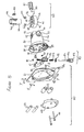
FIG. 7 is an exploded view of the desk-mounting bracket and support arm of FIGS. 1-4;
FIG. 8 is a plan view from above of the assembled apparatus of FIG. 7; and
FIG. 9 is a cross-sectional view along the line A-A of the apparatus of FIG. 8.
DETAILED DESCRIPTION OF EMBODIMENTS
Referring now to the drawings, there is shown a flat-screen monitor support 10 according to the present invention, comprising a body 20, a locking means 40 at a rear portion of the body 20 and a monitor mounting mechanism 60 at a front portion of the body 20. The body 20 comprises a generally cylindrical housing 21 having an upper support arm 22 and a lower support arm 23 extending horizontally and parallel to each other from the rear portion thereof, which together define a space 24 therebetween. Each support arm 22,23 includes a circular aperture 25, 26 extending therethrough, the apertures 25,26 being coaxial and vertically aligned.
The flat-screen monitor support 10 is designed to be mounted on a vertical support post 102 (described in detail below). The locking means 40 comprises a ring member 41 shaped as a toroid with flattened upper and lower surfaces 41 a, 41 b and having a central aperture 42 extending threthrough. Three parallel spines 43 protrude inwardly from around the inner surface of the central aperture 42. A bearing sleeve 44 fits inside the central aperture 42, the bearing sleeve 44 having three grooves 45 extending from one end to approximately halfway along the length of the bearing sleeve 44. The grooves 45 are radially disposed about the outer surface of the bearing sleeve 44 to correspond to the positions of the spines 43 on the ring member 41. Therefore, when the bearing sleeve 44 is inserted into the ring member 41, the spines 43 engage with the grooves 45, and the ring member 41 is able to slide over the bearing sleeve 44 until the spines 43 abut the ends of the grooves 45, thereby preventing the ring member 41 from further movement in that sliding direction relative to the bearing sleeve 44. It will be appreciated that the spines 43 engaged in the grooves 45 also prevents the bearing sleeve 44 being able to rotate relative to the ring member 41 about a common axis of the bearing sleeve 44 and ring member 41.
The ring member 41 has square recess 46 formed in the upper surface 41 a thereof to form an open cavity therein, and a hole 47 extends from the outer circumference of the ring member 41, through the square recess 46 and is open to the central aperture 42. A notch 48 is formed in the edge wall of the central aperture 42 at the point where the hole 47 emerges. A threaded nut 49 is disposed in the square recess 46 and is dimensioned such that two parallel edges of the nut 49 closely abut the side-walls of the square recess 46, thereby preventing the nut 49 from being able to rotate within the square recess 46. A locking bolt 50 having a ridged handle 51 is disposed through the hole 47, is threadingly engaged with the nut 49 and an end of the locking bolt 50 remote from the handle 51 protrudes into the notch 48.
The bearing sleeve 44 has a cut-out portion 52 positioned at a point opposite the end of the locking bolt 50 when the bearing sleeve 44 is fully inserted into the central aperture 42 in the ring member 41. A friction pad 53 is disposed in the cut-out portion 52 and extends into the notch 48, so as to be contacted by the end of the locking bolt 50 when the locking bolt 50 is threaded through the nut 49 towards the notch 48.
When assembled with the body 20, the ring member 41 fits in the space 24 between the upper and lower support arms 22, 23, with the central aperture 42 of the ring member 41 aligned with the circular apertures 25, 26 in the support arms 22, 23 and the upper and lower flattened surfaces 41 a, 41 b lying flush against the adjacent lower and upper faces of the upper and lower support arms 22, 23 respectively. The bearing sleeve 44 extends through the circular aperture 26 in the lower support arm 23, through the central aperture 42 in the ring member 41 and through the circular aperture 25 in the upper support arm 22. In use, the support post 102 (described in more detail hereafter) extends though the bearing sleeve 44, and the ring member 41 is secured thereto by using the ridged handle 51 to screw the locking bolt 50 through the nut 49, thereby forcing the friction pad 53 into engagement with the support post 102 and locking the locking means 40 thereto, and thereby supporting the body 20 at the chosen height on the support post 102. However, the body 20 is still able to rotate in a horizontal plane about the axis of, and relative to, the support post 102/ring member 41/bearing sleeve 44, whilst the locking means 40 is locked to the support post 102.
The front portion of the body 20 includes an outwardly tapering mouth portion 27 which is open to a cavity 28 within the body 20. The monitor mounting mechanism 60 comprises a mounting plate 61 having mounting holes 61 a formed therein, and an arcuate guide plate 62 secured thereto, the guide plate 62 being arcuate about a horizontal axis X-X (see FIG. 5). The guide plate 62 is rectangular and bent into a curve, and is secured at each distal end proximate top and bottom edges of the mounting plate 61, respectively. (However, the guide plate 62 may alternatively be formed integrally with the mounting plate 61 within the scope of the invention). The guide plate 62 curves away from the mounting plate 61 from each secured end towards its middle.
The monitor mounting mechanism 60 is pivotally attached to the body 20 by means of the arcuate guide plate 62 extending into the cavity 28 and resting against curved guide surfaces 29 formed on the tapering mouth portion 27, proximate upper and lower edges of the cavity 28 of the body 20. The mounting plate 61 is held in position by a pair of roller members 63, rotatably disposed on roller pins 64, with the roller members 63 positioned against the guide plate 62 to hold the guide plate 62 against the curved guide surfaces 29. The roller pins 64 are held in position by a clamp plate 65 which traps the distal ends of each of the roller pins 64 in recesses 30 in the mouth portion 27 of the body 20. The clamp plate 65 is secured to the tapering mouth portion 27 of the body 20 by locking bolts 66 which are threadably engaged with corresponding nuts 67 held within the body 20.
It will be appreciated that once assembled, the mounting plate 61 is able to tilt forwards and backwards generally about the horizontal axis X-X in a direction indicated by arrow A (see FIG. 5), as the guide plate 62 slides over the curved guide surfaces 29, held thereagainst by rolling contact with the roller members 63.
The monitor mounting mechanism 60 further includes a tilt adjustment mechanism 80 to selectively secure the mounting plate 61 at a chosen tilt angle. The tilt adjustment mechanism 80 is disposed within the cavity 28 of the body 20, between and behind the curved guide surfaces 29 and behind the arcuate guide plate 62, and comprises a contact member 81 having a curved contact face 82 which contacts the guide plate 62 on an opposite side thereof to the roller members 63 and which is shaped corresponding to the curve of the arcuate guide plate 62. The contact member 81 is able to move vertically within the cavity 28 of the body 20, but is prevented from moving any further rearwards into the cavity 28 by a retaining wall (not shown) against which the contact member 81 abuts and it slidable vertically relative to.
The contact member 81 has a hollow bore 83 extending vertically therethrough in which a threaded adjustment bolt 84 is received. The hollow bore 83 includes an enlarged hexagonal portion 83 a at the upper part of the contact member 81. The adjustment bolt 84 is provided with a ridged handle 85 to facilitate manipulation of the adjustment bolt 84 by a user. The adjustment mechanism 80 further comprises a screw clip 86, upper and lower compression springs 87 a, 87 b, and a retaining nut 88. When assembled, the adjustment bolt 84 extends from the underside of the cylindrical portion 21 of the body 20 into the cavity 28 through an aperture (not shown) in the underside of the body 20, and then through the spring clip 86, through the lower compression spring 87 b, through the hollow bore 83 of the contact member 81, through the upper compression spring 87 a and is threadingly engaged with the retaining nut 88, which is held in the hexagonal portion 83 a of the hollow bore 83 so that it is unable to rotate therein.
The spring clip 86 engages with a recessed groove 86 a in the ridged handle 85, within the cavity 28, to prevent the adjustment bolt 84 from being axially moveable relative to the body 20.
Once assembled, the contact surface 82 of the contact member 81 abuts against the adjacent surface of the guide plate 62, and is prevented from moving away from the guide plate 62 by the retaining wall. The force of the upper compression spring 87 a against the retaining nut 88 and the compression member 81 biases the contact member 81 downwards so that the contact surface 82 is pressed against the guide plate 62, with a force greater than an opposite upwards force exerted by the lower compression spring 87 b against the spring clip 86 and the contact member 81.
At a position where the retaining nut 88 is located at the distal end of the adjustment bolt 84 remote from the ridged handle 85, the upper compression spring 87 a is under little compression and so the contact face 82 of the contact member 81 is only lightly pressed against the guide plate 62. This allows the mounting plate 61 to be tilted relative to the body 20, as the guide plate 62 is able to move relative to the contact member 81 over the guide surfaces 29. However, if a user rotates the adjustment bolt 84 using the ridged handle 85, so that the retaining nut 88 is drawn further down the threaded shaft of the adjustment bolt 84, then the upper compression spring 87 a is placed under increased compression and thereby exerts a greater force on the contact member 81, urging the contact surface 82 into contact with the guide plate 62 with increased force. The resulting increased friction between the contact face 82 and the guide plate 62 prevents these two components from moving relative to each other, and so locks the mounting plate 61, and associated flat screen monitor, at a chosen tilt angle relative to the body 20.
The above-described tilt-adjustment mechanism has the advantage that it gives a finer and more progressive frictional force adjustment that would be obtained if the upper compression spring 87 a was omitted and the threaded nut 67 acted directly on the contact member 81.
In the preferred embodiment of the invention, the arcuate guide plate 62 is curved about an axis along its length Y-Y (see FIG. 5) as well as along the horizontal axis X-X. This results in the arcuate guide plate 62 being shaped as a section of a spherical surface. In this embodiment, the roller members 65 have a curved surface whereby their diameter at the middle is greater than the diameter at the edges (as shown in FIG. 5) such that they are correspondingly curved to the curve along axis Y-Y of the arcuate guide plate 62, so that they are in contact with the surface of the arcuate guide plate 62 across its width. This allows the mounting plate 61 and associated monitor secured thereto, to be pivoted side-to-side about a vertical axis in a direction shown by arrow B (see FIG. 5) relative to the body 20, as well as being able to be tilted forwards and backwards about axis X-X as described above. Such side-to-side motion is therefore independent of, and does not inhibit, the forwards and backwards tilting action shown by arrow A.
The monitor support 10 is intended for use with a table or desk-mountable support structure 100 (see FIGS. 1-4 and 7-9), which comprises a base portion 101 for attachment to a desk or table (‘D’) and a vertical support post 102, which are connected together by one or more elbow joints 103 and connecting members 104. The vertical support post 102 and one or more of the elbow joints 103/connecting members 104 may be formed integrally or may be formed separately and connected together by a connection mechanism 90 (see FIGS. 4 and 7-9) described in more detail below.
The connection mechanism 90 includes a pivot pin 91 comprising an inner spindle 92 and an outer sleeve 93. The outer sleeve 93 has a flange 94 extending radially from its outer circumference midway along its length. Each end of the spindle 92 has a head 95 formed on a boss 96 which protrudes in an axial direction of the spindle 92. Each end of the spindle 92 has a retaining washer 97 located around the boss 96 and extending over the end of the sleeve 93, and a spring washer 98 which acts against the underside of each head 95 to bias the retaining washer 97 onto the respective end of the sleeve 93, thereby keeping the sleeve 93 in place on the spindle 92.
The pivot pin 91 shown in the Figures is only used to connect two connecting members 104 together. However, it may also be used to connect elbow joints 103/the vertical support post 102 and/or the connecting members 104 together, within the scope of the invention. The connection mechanism 90 will be described with reference to the arrangement shown in the Figures whereby two vertical connecting members 104 extending from respective elbow joints 103 are connected together. The pivot pin 91 is partially received in a circular cavity in the end of each respective connecting member 104. Referring to FIG. 9, one half of the pivot pin 91 is inserted into a circular cavity in a lower vertical connecting member 104 a, which extends upwardly from a lower elbow joint 103 a, until the flange 94 abuts the top edge of the lower connecting member 104 a. The spring washer 98 is configured to form a friction fit within the inner surface of the cavity to help keep the pivot pin 91 in place.
The end of the pivot pin 91 remaining exposed and upstanding from the lower connecting member 104 a is inserted into a circular cavity within an upper vertical connecting member 104 b, which extends downwardly from an upper elbow joint 103 b. As described above with the lower connecting member 104 a, the pivot pin 91 is inserted into the cavity until a bottom edge of the upper connecting member 104 b abuts the flange 94 and the spring washer 98 again forms a friction fit within the inner surface of the cavity to help keep the pivot pin 91 in place.
Once the upper and lower connecting members 104 a, 104 b are connected as described above, they are held together by a friction fit that prevents them from easily sliding apart, unless sufficient force is exerted in an axial direction of the pivot pin 91 on each connecting member 104 a, 104 b to separate them. However, the pivot pin 91 allows the two connecting members 104 a, 104 b to rotate relative to each other about the axis of the pivot pin 91. With reference to FIG. 4, it will be appreciated that this rotational ability allows the flat screen monitor support 10, and thereby, a flat screen monitor attached thereto, to be positioned in a range of locations in a horizontal plane relative to the base portion 101 secured to the desk or table D.
The support structure shown in FIGS. 1-4 and 7-9 includes a lower arm assembly 100A and an upper arm assembly 100B. The lower arm assembly 100A comprises the lower connecting member 104 a, lower elbow joint 103 a, a lower lateral connecting member 104 c connected at one end to the lower elbow joint 103 a and at its other end, to a base elbow joint 103 c, and a base connecting member 104 d extending vertically downwards from the base elbow joint 103 c. The upper arm assembly 100B comprises the vertical support post 102, a support post elbow joint 103 d, an upper lateral connecting member 104 e, the upper elbow joint 103 b and upper connecting member 104 b. The support post 102 includes a retaining disc 102 a at a distal end thereof remote from the support post elbow joint 103 d, which is held in place on the support post 102 by a retaining bolt 102 b (see, in particular, FIG. 4). In the illustrated embodiment, the lower and upper arm assemblies 100A, 100B are respectively formed as one integral component. However, the base connecting member 104 d, base and lower elbow joints 103 c, 103 a and lower lateral and lower connecting members 104 c, 104 a of the lower arm assembly 100A and, the vertical support post 102, support post elbow joint 103 d, upper lateral connecting member 104 e, upper elbow joint 103 b and upper connecting member 104 b of the upper arm assembly 100B, may be formed separately and be detachable or permanently connected within the scope of the invention.
Referring now to FIGS. 7-9, the base portion 101 of the support structure 100 will be described in more detail. The base portion 101 comprises a base cup 110, a bearing disc 120, a main bracket 130, and a swivel plate 140 and a lower bracket 150.
The base cup 110 is made of rubber or an equally suitable resilient material, and comprises a flat base 111 with a wall 112 upstanding vertically from the perimeter thereof. The wall 112 extends around approximately three-quarters of the perimeter of the flat base 111, and includes a gap 113 around the remaining one quarter of the perimeter.
A ridge 114 protrudes inwardly from the join of the wall 112 and the flat base 111 towards the centre of the flat base 111, and extends around approximately one quarter of the circumference of the flat base 111. This ridge 114 provides a means to limit rotation of the support structure swivel plate 140 about the base cup 110, as will be described in more detail below.
The bearing disc 120 comprises a flat portion 121 with a central aperture 122, and a circular raised portion 123 at the middle of the flat portion 121 disposed around the central aperture 122. The beating disc 120 is preferably made of a hard plastic material, and acts to reduce frictional contact between the main bracket 130 and the swivel plate 140.
The main bracket 130 is substantially ‘L’-shaped in cross-section and has a first portion 131 formed as a circular plate with a central aperture 132 therethrough, and a second, rectangular portion 133 substantially at right-angles to the first portion 131, and provided with a plurality of threaded apertures 134 formed in two lines proximate the side edges thereof.
The lower bracket 150 is substantially ‘L’-shaped in cross-section and comprises a first, horizontal portion 151, and a second, vertical portion 152 perpendicular to the first portion 151. The lower bracket 150 is secured to the main bracket 130 by threaded bolts 153 which extend through holes 154 in the second portion 152 and are threadingly engaged in the threaded apertures 134 of the second portion 133 of the main bracket 130. The first portion 131 of the main bracket 130 and the first portion 151 of the lower bracket are thereby parallel to each other. The first portion 151 of the lower bracket includes two threaded apertures 155 therethrough which receive correspondingly threaded clamp bolts 156. The lower end of each clamp bolt 156 has a handle portion 157 and the opposite end of each clamp bolt 156 has a clamp pad 158 attached thereto. As the second portion 133 of the main bracket 130 includes a plurality of threaded apertures 134, the lower bracket 150 can be secured to the most appropriate ones such that the gap between the first portion 131 of the main bracket 130 and the first portion 151 of the lower bracket 150 is sized to fit the table or desk top D to which the base portion 101 is to be attached.
The end of the base connecting member 104 d remote from the base elbow joint 103 c is secured to the centre of the swivel plate 140. In the embodiment shown and described, the swivel plate 140 is welded to the base connecting member 104 d. However, other means of attachment may be used to secure the swivel disc 140 to the base connecting member 104 d within the scope of the invention. The swivel plate 140 is a circular disc 141, which has a segment 142 protruding radially beyond the circumference of the remainder of the disc 141 over approximately one quarter of the perimeter thereof.
The base portion 101 is assembled by passing the lower arm assembly 100A—with the lower connecting member 104 a first—through the aperture 122 in the bearing disc 120, then through the aperture 132 in the main bracket 130 until the lower surface of the bearing disc 120 rests against the upper surface of the swivel plate 140, and the upper surface of the bearing disc rests against the underside of the first portion 131 of the main bracket 130, with the circular raised portion 123 of the bearing disc 120 protruding through the aperture 132 in the main bracket 130.
The aperture 122 in the bearing disc 120 is sized to snugly fit around the base connecting member 104 d, and the aperture 131 in the main bracket 130 is sized to fit snugly around the circular raised portion 123 of the bearing plate 120, so that lateral play between the three components is substantially eliminated.
To secure this assembly of components to a desk or table top D, the base cup 110 is placed on the upper surface of the table top D, and the main bracket 130, bearing disc 120 and lower arm assembly 100A, including attached swivel plate 140, are positioned so that the swivel plate 140 sits within the base cup 110 with the first portion 151 of the lower bracket 150 extending horizontally underneath the table top D below the first portion 131 of the main bracket 130. The clamp bolts 156 are then tightened using the clamp handles 157 until the clamp pads 158 engage with the underside of the table top D and thereby secure the base portion 101 in position as shown in FIG. 9.
From FIGS. 1, 2, 4 and 9, it can be seen that the first portion 131 of the main bracket 130 extends from the base cup 110 through the gap 113 in the wall 112 so that the top of the first portion 131 of the main bracket 130 is below the level of the wall 112, so that the wall 112 covers the side edges of the first portion 131 and the bearing disc 120. Referring to FIG. 7, the base portion 101 is configured such that rotational movement of the swivel plate 140 relative to the base cup 110 is limited and does not permit 360 degree rotation. The diameter of the swivel plate 140 is such that it fits within the base cup 110 with the ridge 114 abutting the outer perimeter of the swivel disc 140. The lower arm assembly 100A and swivel disc 140 are thereby able to rotate relative to the base cup 110 until the protruding segment 142 rotates round and reaches the ridge 114. At this point, the ridge 114 acts as a stop against which the protruding segment 142 abuts, thereby preventing further rotation of the swivel plate 140 and lower arm assembly 100A relative to the base cup 110 in that direction. It will be appreciated that the length of the ridge 114 and of the protruding segment 142—i.e. the proportion of the circumference of the base cup 110/swivel plate 140 about which they respectively extend—can be specified at the manufacturing stage for a predetermined degree of rotation of the lower arm assembly 100A and associated monitor support 10 and attached monitor, relative to the base cup 110, and therefore, relative to the desk or table top D to which the support structure 100 is secured.
Referring to FIG. 4, the support structure 100 further includes one or more cable clips 105. These are moulded plastic components formed as a large ‘C’ shape 105 a, with a smaller ‘c’ 105 b extending from one end and within the larger ‘C’ portion 105 a. The allows the smaller ‘c’ portion 105 b to snap-fit around the vertical support post 102 or other part of the support structure 100, and wires from the monitor to be tidily bunched together within the larger ‘C’ portion 105 a of the cable clip 105. It will be noted that only one end of the larger ‘C’ portion 105 a is connected to the smaller ‘c’ portion 105 b, to enable wires to be placed within the larger ‘C’ portion 105 a without having to be fed in from a distal end of the wire.
Operation of the above-described monitor support will now be described. A flat-screen monitor (not shown) is secured to the mounting plate 61 using conventional means such as screws (not shown) secured through mounting holes 61 a into corresponding screw holes in a rear face of the monitor.
The support structure 100 is assembled and secured to a desk or table top D as described above, leaving the vertical support post 102 upstanding therefrom without the retaining disc 102 a on retaining bolt 102 b secured threeto. The monitor support 10 with associated monitor is then attached to the support structure 100 by passing the vertical support post 102 through the bearing sleeve 44, and the locking bolt 50 is then tightened using the ridged handle 51 to press the friction pad 53 into engagement with the vertical support post 102 to lock the locking mechanism 40 thereto. This secures the body 20 at a desired height. The retaining disc 102 a is then secured to the support post 102 by the retaining bolt 102 b. The diameter of the retaining disc 102 a is greater than that of the support post 102, the apertures 25,26 in the support arms 22,23 and the inner diameter of the bearing sleeve 44, so that once the retaining disc 102 a has been secured in place, the monitor support 10 is unable to be slid off the top of the support post 102.
The user may then adjust the angle of the monitor relative to the locking mechanism 40 by rotating the body 20 about the vertical support post 102. The user may also alter the forwards-backwards tilt angle and the sideways tilt angle of the monitor relative to the body 20 by manipulating the mounting plate 61 relative to the body 20 in the directions shown by arrows A and B, as described above. Once in the chosen position, the user then tightens the tilt adjustment mechanism 80 by rotating the adjustment bolt 84 so that the retaining nut 88 is drawn along the adjustment bolt, thereby increasing the compression of the upper compression spring 87 a, and causing the contact member 81 to prevent further movement of the mounting plate 61 relative to the body 20, as described above.
It will be appreciated that the locking mechanism 40 is operable to bind to any location on the post and so there are no discrete spaced apart mounting points or steps which the user must select. The user may therefore position the monitor at any desired location along the length of the post.
However, alternative embodiments of the present invention are intended to fall within the scope of the invention, as defined by the claims hereafter. For example, the vertical support post may have discrete grooves formed therein, and/or the bearing sleeve 44 may omit the friction pad 53 so that the locking bolt 50 acts directly on the vertical support post 102, and may therefore engage in one of the discrete grooves to lock the monitor support at a chosen height on the vertical support post 102.
In the exemplary embodiment described above, the apertures 25, 26, in the support arms 22, 23 of the body 20, and the aperture 42 in the ring member 41 are rounded, to fit a correspondingly round vertical support post 102. However, they may be of alternative shapes within the scope of the invention, for example, oval, square, or rectangular, to fit a correspondingly shaped support post. However, such embodiments would not permit the body 20 to rotate relative to the support post 102 and ring member 41, as in the embodiment shown and described above.
Any suitable material may be used to make the various components described above, for example, metal, such as steel or aluminium, or any suitable plastics material. The base cup 110 may be made of an alternative material to rubber, such as metal or a plastics material. Likewise, the bearing plate 120 may be made of metal, plastic, or any other suitable material.
Although the swivel plate 140 is described as being substantially circular, it may be of an alternative shape within the scope of the invention, for example, of a rectangular shape, or a ‘bow-tie’ shape, such that the main bracket 130 and base cup 110 are still able secure the support structure 100 and allow rotation, with a limit of rotation provided by the ridge 114, as described above.
It will be appreciated by those skilled in the art that variations may be made to the above exemplary embodiment within the scope of the invention, which is defined in the claims hereafter.

Claims (18)

1. A flat-screen monitor support, comprising:
a body having means for attachment of a monitor thereto; and
a locking means operable to lock against a support post extending through the body and through the locking means and to support the body to prevent the body from sliding down the post under the weight of a monitor attached to the body, the body being rotatable relative to the locking means about an axis of a support post extending through the body and locking means, when the locking mechanism is locked to the support post, wherein the locking means comprises a ring member and the body includes upper and lower support arms which extend from either side of the ring member such that, in use, a support post extends through an aperture in the lower support arm, through the ring member and through an aperture in the upper support arm.
2. A monitor support according to claim 1, further comprising a bearing sleeve extending through the support arms and ring member and through which, in use, a support post extends.
3. A monitor support according to claim 2, wherein the locking means comprises an actuator operable to lock or disengage the locking means to/from the support post.
4. A monitor support according to claim 3, wherein the actuator comprises a threaded locking bolt extending through the ring member and operable to exert pressure against the support post extending though the ring member to lock the monitor support thereto.
5. A monitor support according to claim 4, wherein the ring member includes a nut secured within the ring member, through which the locking bolt extends as it extends through the ring member and with which it is threadingly engaged in order to allow the locking bolt to be tightened against the support post.
6. A monitor support according to claim 5, wherein the bearing sleeve includes an aperture disposed adjacent the end of the locking bolt in order to allow the end of the locking bolt to directly engage the support post.
7. A monitor support according to claim 5, wherein the bearing sleeve includes an aperture disposed adjacent the end of the locking bolt and a friction pad disposed in said aperture in order to allow the end of the locking bolt to exert pressure on the friction pad and thereby cause the friction pad to engage the surface of the support post.
8. A monitor support according to claim 1, the means for attachment of a monitor to the body comprises a mounting plate attached to the body.
9. A monitor support according to claim 8, further comprising a tilting mechanism that allows the mounting plate to pivot relative to the body about a substantially horizontal axis.
10. A monitor support according to claim 9, wherein the tilting mechanism comprises the mounting plate having an arcuate guide member curved about a first, horizontal, axis and slidably secured to the body such that the mounting plate may pivot relative to the body about the first axis, as the arcuate guide member slides relative to the body.
11. A monitor support according to claim 10, further comprising at least one guide roller in contact with the arcuate guide member to bias the guide member against a sliding surface of the body, so that as the mounting plate tilts, the arcuate guide member slides between the sliding surface and the at least one guide roller.
12. A monitor support according to claim 11, wherein the at least one guide roller is mounted on a shaft and is secured to the body by a clamp plate that traps the shaft between it and the body.
13. A monitor support according to claim 10 wherein the arcuate guide member is curved about a second axis across its width so as to resemble a portion of a surface of a sphere, such that the mounting plate is capable of swivelling relative to the housing about a substantially vertical axis perpendicular to the first axis.
14. A monitor support according to claim 13, wherein the at least one guide roller surface is curved across its width to correspond to the curved surface of the arcuate guide member.
15. A monitor support according to claim 10, wherein a contact member is disposed within the housing in adjustable frictional contact with the arcuate guide member, operable to lock or allow sliding movement of the arcuate guide member.
16. A monitor support according to claim 15, wherein the contact member includes an adjustment mechanism to enable the frictional contact force to be adjusted.
17. A monitor support according to claim 16, wherein the adjustment mechanism comprises the contact member being received on a threaded post, and a compression spring is disposed on the post such that rotation of the threaded post alters the compression of the spring and thereby alters the force with which the contact member is biased against the arcuate guide member.
18. A monitor support according to claim 17, wherein the contact member includes a contact face which contacts the arcuate guide member, the contact face being curved to match the curvature of the arcuate guide member.
US12/532,258 2007-03-22 2008-03-20 Flat-screen monitor support Active 2028-04-18 US8066232B2 (en)

Applications Claiming Priority (3)

Application Number Priority Date Filing Date Title
GB0705479.4A GB2447623B8 (en) 2007-03-22 2007-03-22 Flat-screen monitor support
GB0705479.4 2007-03-22
PCT/EP2008/053413 WO2008113860A2 (en) 2007-03-22 2008-03-20 Flat-screen monitor support

Publications (2)

Publication Number Publication Date
US20100148020A1 US20100148020A1 (en) 2010-06-17
US8066232B2 true US8066232B2 (en) 2011-11-29

Family

ID=38024613

Family Applications (1)

Application Number Title Priority Date Filing Date
US12/532,258 Active 2028-04-18 US8066232B2 (en) 2007-03-22 2008-03-20 Flat-screen monitor support

Country Status (4)

Country Link
US (1) US8066232B2 (en)
CN (1) CN101680595B (en)
GB (1) GB2447623B8 (en)
WO (1) WO2008113860A2 (en)

Cited By (9)

* Cited by examiner, † Cited by third party
Publication number Priority date Publication date Assignee Title
US20130161466A1 (en) * 2010-06-09 2013-06-27 Alex Lau Support system
US20150090055A1 (en) * 2013-09-30 2015-04-02 GOJO Industries, Inc., Universal mounting assembly for sensing device
US20160084432A1 (en) * 2014-09-23 2016-03-24 Kelly International Corp. Self-positionable lifting device
US9316346B2 (en) 2010-06-09 2016-04-19 Colebrook Bosson Saunders (Products) Limited Support system
US20160357999A1 (en) * 2015-06-03 2016-12-08 Wistron Corp. Rotatable assembly and scanning device including the same
US20190309894A1 (en) * 2016-12-28 2019-10-10 Panasonic Intellectual Property Management Co., Ltd. Display device and stand set
USD1005984S1 (en) 2010-08-11 2023-11-28 Colebrook Bosson & Saunders (Products) Limited Indicator window for a display support
US11856347B1 (en) 2020-01-16 2023-12-26 David M. Roberts Speaker stand
US11933450B2 (en) 2021-05-12 2024-03-19 Colebrook Bosson & Saunders (Products) Limited Tilt head for high load display support system

Families Citing this family (20)

* Cited by examiner, † Cited by third party
Publication number Priority date Publication date Assignee Title
GB2456018A (en) * 2007-12-31 2009-07-01 Colebrook Bosson Saunders Prod Monitor support apparatus
US8448906B2 (en) 2008-08-21 2013-05-28 Knoll, Inc. Support apparatus
US8814224B2 (en) * 2009-11-11 2014-08-26 Hoffman Enclosures, Inc. Enclosure suspension system with compression fitting
GB2481047A (en) * 2010-06-09 2011-12-14 Colebrook Bosson & Saunders Products Ltd A mounting system for pivotally mounting a flat screen display
US8342462B2 (en) 2010-06-11 2013-01-01 Knoll, Inc. Support apparatus
FR2961887B1 (en) * 2010-06-29 2014-01-03 Id Ind & Design HOLDING DEVICE IN ADJUSTABLE POSITION ALONG A MATT AND ORIENTABLE AROUND THE AXIS OF THE MAT
US20130112828A1 (en) 2011-06-07 2013-05-09 Knoll, Inc. Support Apparatus for Display Devices and Other Objects
US8651444B2 (en) 2011-09-23 2014-02-18 Knoll, Inc. Friction adjustment mechanism for a support apparatus
CN103032663A (en) * 2011-10-09 2013-04-10 日进教学器材(昆山)有限公司 Adjustable-height universal revolving device
CN102705652A (en) * 2012-06-15 2012-10-03 苏州市庆鼎精密机械制品有限公司 Support for TV set
US9400083B2 (en) 2014-04-24 2016-07-26 Knoll, Inc. Support apparatus for multiple display devices
CN105757412A (en) * 2016-04-18 2016-07-13 义乌市吉浦文具用品有限公司 Fastening part of liquid crystal display equipment and application method of fastening part
CN106346172A (en) * 2016-11-09 2017-01-25 南京奥特电气股份有限公司 All-dimensional welding operation and control device
CN107631142A (en) * 2017-09-09 2018-01-26 浙江居优智能科技有限公司 A kind of display rotating support
CN108361491A (en) * 2018-01-29 2018-08-03 湖北旭兴达科技有限公司 A kind of intelligent monitoring holder
CN108361507A (en) * 2018-05-21 2018-08-03 菏泽学院 A kind of portable mechanism electronic product machining sets back-up monitoring equipment
US10323791B1 (en) * 2018-06-06 2019-06-18 C. D. Great Furniture Co., Ltd. Displacement structure for a support frame
US11378225B2 (en) 2018-09-07 2022-07-05 Apple Inc. Display support arm mount
TWM583958U (en) * 2019-02-01 2019-09-21 信錦企業股份有限公司 Supporting device
CN114909561B (en) * 2019-05-31 2024-02-27 苹果公司 Display support arm mounting rack

Citations (24)

* Cited by examiner, † Cited by third party
Publication number Priority date Publication date Assignee Title
US3297291A (en) 1965-02-03 1967-01-10 Ednalite Corp Articulate support arm assembly for optical devices
US3997645A (en) * 1974-10-08 1976-12-14 Canathane Roller Corporation Method of rotational molding a rectangular mat
US4577819A (en) * 1984-05-14 1986-03-25 Bennett Richard C Self-balancing boom apparatus
US5039043A (en) 1990-04-05 1991-08-13 Hodge Robert B Post holder
US5092552A (en) 1982-10-04 1992-03-03 Wang Laboratories, Inc. Ergonomic equipment arm
NL9100552A (en) 1991-03-28 1992-10-16 Cambo Fotografische Ind B V Adjustable camera stand - movable along column by means angle of pulley, and lockable by lever with respect to azimuth position and height
US5751548A (en) 1996-05-13 1998-05-12 International Business Machines Corporation Docking station for a portable computer providing rotational movement of the computer's viewable screen in three different planes
CN2284557Y (en) 1996-08-12 1998-06-24 翁端明 Hidden leftovers holder for dining table
US6220556B1 (en) * 1999-05-28 2001-04-24 Thomas M. Sohrt Universally adjustable mounting system for switches, or the like
EP1139003A2 (en) 2000-03-30 2001-10-04 Peter Thomas Bosson Display device support system
US20030075653A1 (en) * 2001-10-19 2003-04-24 Chin-Chu Li Liquid crystal display support
GB2394505A (en) 2002-10-11 2004-04-28 David Preston A slidable and rotatable clamp arrangement for an angler's seat box
WO2004051135A1 (en) 2002-12-05 2004-06-17 Koninklijke Philips Electronics N.V. Display system with a stationary supporting base
US20040144903A1 (en) * 2003-01-23 2004-07-29 Cherubini Julian H. Apparatus for holding a vial
EP1471300A2 (en) 2003-03-31 2004-10-27 Vogel's Holding B.V. Device suitable for supporting a component
WO2005124220A1 (en) 2004-06-10 2005-12-29 Humanscale Corporation Mechanism for positional adjustment of an attached device
DE202005019110U1 (en) 2005-12-06 2006-02-23 Harvest-Excel International Pte. Ltd. Mounting for a computer monitor is articulated and allows horizontal and vertical adjustment
US20070040084A1 (en) * 2005-06-03 2007-02-22 Lane Sturman Support arm assembly
CN2879355Y (en) 2006-03-06 2007-03-14 姜艺 Double-rocker telescopic wall hanging support
US20080029661A1 (en) * 2006-07-19 2008-02-07 Hoolin Research Company Limited Monitor support structure
US7510155B2 (en) * 2007-07-02 2009-03-31 Shian-Nung Huang Single spring supporting device
US20090090831A1 (en) * 2003-07-11 2009-04-09 Henning Gerald W Flat panel monitor support arm
US7546993B1 (en) * 2008-03-25 2009-06-16 Tyco Healthcare Group Lp Flexible clamping apparatus for medical devices
US7766288B2 (en) * 2006-03-08 2010-08-03 Samsung Electronics Co., Ltd. Display apparatus

Family Cites Families (1)

* Cited by examiner, † Cited by third party
Publication number Priority date Publication date Assignee Title
JP4413061B2 (en) * 2004-04-09 2010-02-10 株式会社村上開明堂 Display holding device

Patent Citations (25)

* Cited by examiner, † Cited by third party
Publication number Priority date Publication date Assignee Title
US3297291A (en) 1965-02-03 1967-01-10 Ednalite Corp Articulate support arm assembly for optical devices
US3997645A (en) * 1974-10-08 1976-12-14 Canathane Roller Corporation Method of rotational molding a rectangular mat
US5092552A (en) 1982-10-04 1992-03-03 Wang Laboratories, Inc. Ergonomic equipment arm
US4577819A (en) * 1984-05-14 1986-03-25 Bennett Richard C Self-balancing boom apparatus
US5039043A (en) 1990-04-05 1991-08-13 Hodge Robert B Post holder
NL9100552A (en) 1991-03-28 1992-10-16 Cambo Fotografische Ind B V Adjustable camera stand - movable along column by means angle of pulley, and lockable by lever with respect to azimuth position and height
US5751548A (en) 1996-05-13 1998-05-12 International Business Machines Corporation Docking station for a portable computer providing rotational movement of the computer's viewable screen in three different planes
CN2284557Y (en) 1996-08-12 1998-06-24 翁端明 Hidden leftovers holder for dining table
US6220556B1 (en) * 1999-05-28 2001-04-24 Thomas M. Sohrt Universally adjustable mounting system for switches, or the like
EP1139003A2 (en) 2000-03-30 2001-10-04 Peter Thomas Bosson Display device support system
US20030075653A1 (en) * 2001-10-19 2003-04-24 Chin-Chu Li Liquid crystal display support
GB2394505A (en) 2002-10-11 2004-04-28 David Preston A slidable and rotatable clamp arrangement for an angler's seat box
WO2004051135A1 (en) 2002-12-05 2004-06-17 Koninklijke Philips Electronics N.V. Display system with a stationary supporting base
US20040144903A1 (en) * 2003-01-23 2004-07-29 Cherubini Julian H. Apparatus for holding a vial
EP1471300A2 (en) 2003-03-31 2004-10-27 Vogel's Holding B.V. Device suitable for supporting a component
US20090090831A1 (en) * 2003-07-11 2009-04-09 Henning Gerald W Flat panel monitor support arm
WO2005124220A1 (en) 2004-06-10 2005-12-29 Humanscale Corporation Mechanism for positional adjustment of an attached device
US20050284991A1 (en) 2004-06-10 2005-12-29 Humanscale Corporation Mechanism for positional adjustment of an attached device
US20070040084A1 (en) * 2005-06-03 2007-02-22 Lane Sturman Support arm assembly
DE202005019110U1 (en) 2005-12-06 2006-02-23 Harvest-Excel International Pte. Ltd. Mounting for a computer monitor is articulated and allows horizontal and vertical adjustment
CN2879355Y (en) 2006-03-06 2007-03-14 姜艺 Double-rocker telescopic wall hanging support
US7766288B2 (en) * 2006-03-08 2010-08-03 Samsung Electronics Co., Ltd. Display apparatus
US20080029661A1 (en) * 2006-07-19 2008-02-07 Hoolin Research Company Limited Monitor support structure
US7510155B2 (en) * 2007-07-02 2009-03-31 Shian-Nung Huang Single spring supporting device
US7546993B1 (en) * 2008-03-25 2009-06-16 Tyco Healthcare Group Lp Flexible clamping apparatus for medical devices

Non-Patent Citations (4)

* Cited by examiner, † Cited by third party
Title
International Search Report for Internation Application No. PCT/EP2008/053413, completed Jul. 17, 2008; 7 pages.
Notification of the First Office Action (PCT), corresponding to Application No. 200880018402.3, dated Nov. 12, 2010; 2 pages.
Patents Act 1977: Further Search Report under Section 17 corresponding to Application No. GB 0705479.4, dated Jun. 13, 2011; 1 page.
Patents Act 1977: Search Report under Section 17 corresponding to Application No. GB 0705479.4, dated Jun. 22, 2007; 1 page.

Cited By (13)

* Cited by examiner, † Cited by third party
Publication number Priority date Publication date Assignee Title
US9572269B2 (en) 2010-06-09 2017-02-14 Colebrook Bosson Saunders (Products) Limited Support system
US9074721B2 (en) * 2010-06-09 2015-07-07 Alex Lau Support system
US20130161466A1 (en) * 2010-06-09 2013-06-27 Alex Lau Support system
US9316346B2 (en) 2010-06-09 2016-04-19 Colebrook Bosson Saunders (Products) Limited Support system
USD1005984S1 (en) 2010-08-11 2023-11-28 Colebrook Bosson & Saunders (Products) Limited Indicator window for a display support
US20150090055A1 (en) * 2013-09-30 2015-04-02 GOJO Industries, Inc., Universal mounting assembly for sensing device
US20160084432A1 (en) * 2014-09-23 2016-03-24 Kelly International Corp. Self-positionable lifting device
US10032054B2 (en) * 2015-06-03 2018-07-24 Wistron Corp. Rotatable assembly and scanning device including the same
US20160357999A1 (en) * 2015-06-03 2016-12-08 Wistron Corp. Rotatable assembly and scanning device including the same
US20190309894A1 (en) * 2016-12-28 2019-10-10 Panasonic Intellectual Property Management Co., Ltd. Display device and stand set
US10844996B2 (en) * 2016-12-28 2020-11-24 Panasonic Intellectual Property Management Co., Ltd. Display device and stand set
US11856347B1 (en) 2020-01-16 2023-12-26 David M. Roberts Speaker stand
US11933450B2 (en) 2021-05-12 2024-03-19 Colebrook Bosson & Saunders (Products) Limited Tilt head for high load display support system

Also Published As

Publication number Publication date
GB2447623B (en) 2011-10-26
CN101680595B (en) 2012-05-09
CN101680595A (en) 2010-03-24
GB2447623A8 (en) 2018-01-03
GB2447623A (en) 2008-09-24
GB2447623B8 (en) 2018-01-03
WO2008113860A3 (en) 2008-11-06
GB0705479D0 (en) 2007-05-02
WO2008113860A2 (en) 2008-09-25
US20100148020A1 (en) 2010-06-17

Similar Documents

Publication Publication Date Title
US8066232B2 (en) Flat-screen monitor support
US5553820A (en) Adjustable monitor arm
US8448906B2 (en) Support apparatus
US10744050B2 (en) Wheelchair back mounting assembly
KR100500234B1 (en) Display apparatus
GB2438581A (en) Adjustable support bracket for a flat-screen monitor
US4703909A (en) Ergonomic equipment arm
US4564166A (en) Rotary tilt base for video terminal
US8710342B2 (en) Steplessly adjustable cymbal locating device
EP1496776A2 (en) Multiple electronic device reorienting support
JPS61161531A (en) Computer equipment mounting unit
US8632042B2 (en) Tilt and swivel mounting for monitors and other devices
US20190072229A1 (en) Adjustable support arm assembly
US8243213B2 (en) Monitor apparatus
US7415785B1 (en) Craft hoop lap stand
US5913498A (en) Adjustable cantilever foot assembly for furniture
US6193315B1 (en) Backrest structure of a chair, particularly a drum chair
EP0105076A1 (en) Ergonomic equipment arm
US20090304377A1 (en) Rotary joint device, support frame and camera apparatus
JP2759701B2 (en) Placement devices such as telephones
KR200304861Y1 (en) A fishing support
JP3077169U (en) Monitor angle adjustment device
JP2508699Y2 (en) Chair seat tilting device
JPH0468945A (en) Mount device for telephone set or the like
JP2601375B2 (en) Angle adjustment mechanism for mounting table such as telephone

Legal Events

Date Code Title Description
AS Assignment

Owner name: COLEBROOK BOSSON SAUNDERS PRODUCTS LTD.,UNITED KIN

Free format text: ASSIGNMENT OF ASSIGNORS INTEREST;ASSIGNORS:WILLS, ANDREW;EZURE, SEIYO;LAU, ALEX;SIGNING DATES FROM 20091021 TO 20091026;REEL/FRAME:023829/0959

Owner name: COLEBROOK BOSSON SAUNDERS PRODUCTS LTD., UNITED KI

Free format text: ASSIGNMENT OF ASSIGNORS INTEREST;ASSIGNORS:WILLS, ANDREW;EZURE, SEIYO;LAU, ALEX;SIGNING DATES FROM 20091021 TO 20091026;REEL/FRAME:023829/0959

STCF Information on status: patent grant

Free format text: PATENTED CASE

FEPP Fee payment procedure

Free format text: PAYOR NUMBER ASSIGNED (ORIGINAL EVENT CODE: ASPN); ENTITY STATUS OF PATENT OWNER: SMALL ENTITY

FPAY Fee payment

Year of fee payment: 4

MAFP Maintenance fee payment

Free format text: PAYMENT OF MAINTENANCE FEE, 8TH YR, SMALL ENTITY (ORIGINAL EVENT CODE: M2552); ENTITY STATUS OF PATENT OWNER: SMALL ENTITY

Year of fee payment: 8

MAFP Maintenance fee payment

Free format text: PAYMENT OF MAINTENANCE FEE, 12TH YR, SMALL ENTITY (ORIGINAL EVENT CODE: M2553); ENTITY STATUS OF PATENT OWNER: SMALL ENTITY

Year of fee payment: 12