US8042393B2 - Arrangement for measuring a rate of rotation using a vibration sensor - Google Patents
Arrangement for measuring a rate of rotation using a vibration sensor Download PDFInfo
- Publication number
- US8042393B2 US8042393B2 US12/443,664 US44366407A US8042393B2 US 8042393 B2 US8042393 B2 US 8042393B2 US 44366407 A US44366407 A US 44366407A US 8042393 B2 US8042393 B2 US 8042393B2
- Authority
- US
- United States
- Prior art keywords
- measuring
- capacitive
- frequency
- arrangement
- vibration
- Prior art date
- Legal status (The legal status is an assumption and is not a legal conclusion. Google has not performed a legal analysis and makes no representation as to the accuracy of the status listed.)
- Expired - Fee Related, expires
Links
Images


Classifications
-
- G—PHYSICS
- G01—MEASURING; TESTING
- G01C—MEASURING DISTANCES, LEVELS OR BEARINGS; SURVEYING; NAVIGATION; GYROSCOPIC INSTRUMENTS; PHOTOGRAMMETRY OR VIDEOGRAMMETRY
- G01C19/00—Gyroscopes; Turn-sensitive devices using vibrating masses; Turn-sensitive devices without moving masses; Measuring angular rate using gyroscopic effects
- G01C19/56—Turn-sensitive devices using vibrating masses, e.g. vibratory angular rate sensors based on Coriolis forces
- G01C19/5705—Turn-sensitive devices using vibrating masses, e.g. vibratory angular rate sensors based on Coriolis forces using masses driven in reciprocating rotary motion about an axis
- G01C19/5712—Turn-sensitive devices using vibrating masses, e.g. vibratory angular rate sensors based on Coriolis forces using masses driven in reciprocating rotary motion about an axis the devices involving a micromechanical structure
-
- G—PHYSICS
- G01—MEASURING; TESTING
- G01C—MEASURING DISTANCES, LEVELS OR BEARINGS; SURVEYING; NAVIGATION; GYROSCOPIC INSTRUMENTS; PHOTOGRAMMETRY OR VIDEOGRAMMETRY
- G01C19/00—Gyroscopes; Turn-sensitive devices using vibrating masses; Turn-sensitive devices without moving masses; Measuring angular rate using gyroscopic effects
- G01C19/56—Turn-sensitive devices using vibrating masses, e.g. vibratory angular rate sensors based on Coriolis forces
Definitions
- the invention relates to an arrangement for measuring a rate of rotation using a vibration sensor. Vibration that is perpendicular to a first axis is excited and measured with the aid of capacitive drive elements, and the rotation about a second axis, which is excited by rotation in a third axis under the action of the Coriolis force, is measured with the aid of capacitive measuring elements, the capacitive elements each being formed by fixed electrodes and by electrodes which can be moved with the vibration sensor, the movable electrodes being jointly connected to a fixed connection.
- Rate of rotation sensors are used, for example, in safety systems for motor vehicles.
- a vibration sensor in the form of a gyroscope has been disclosed, for example, in U.S. Pat. No. 5,955,668.
- the rotational vibration is excited with the aid of electrostatic drives.
- the output signal and a signal for regulating the drives are likewise obtained electrostatically, by means of capacitance measurements with the aid of supplied AC voltages.
- the amplitude of the AC voltage supplied to the drive is considerably greater than that of the signals obtained from the change in capacitance, with the result that, in particular, the output signal to be processed further in order to determine the rate of rotation is subject to considerable interference. This impairs the measurement accuracy.
- An object of the present invention is to specify an arrangement for measuring a rate of rotation, the accuracy of which satisfies high demands and which has a large dynamic range, such that very low rates of rotation are also measured with sufficient accuracy, while no overdriving occurs at high rates of rotation.
- fixed electrodes of the capacitive drive elements are supplied with excitation voltages, the frequency of which correspond to the resonant frequency or to a subharmonic of the resonant frequency of the vibration sensor.
- the capacitive elements, which are used to measure the excited vibration can be supplied with an AC voltage at a first measuring frequency which is higher than the frequency of the excitation voltages.
- the fixed electrodes of the capacitive measuring elements are supplied with AC voltages at a second measuring frequency which differs from the first measuring frequency and is higher than the frequency of the excitation voltages.
- further capacitive measuring elements are provided for the purpose of measuring the excited vibration or the capacitive drive elements are used to measure the excited vibration.
- one advantageous and interference-proof possible way of obtaining the output signal, which describes the rate of rotation is to use means which, in order to form a signal which represents the rate of rotation, synchronously demodulates a signal tapped off from the fixed connection using the AC voltage at the second measuring frequency and then using the excitation voltage.
- Another embodiment of the invention provides means to demodulate the signal tapped off from the fixed connection using the first measuring frequency and use the demodulated signal to regulate the excitation voltages.
- the arrangement with considerable AC voltages for driving and to use the signals, which are taken from the second capacitive elements, for the purpose of regulating the drive and the signals that are taken from the third capacitive elements for the purpose of forming the rate of rotation signal are also extremely small.
- these signals can be evaluated in an effective manner using, for example, low-noise amplifiers.
- a charge amplifier whose output is connected to a bandpass filter, is connected to the fixed connection.
- another embodiment involves providing at least four groups of capacitive drive elements, antiphase AC voltage components and the same bias voltages respectively being applied to two of said groups.
- the frequencies or the ratios of the frequencies can be selected, in detail, the frequencies or the ratios of the frequencies to one another taking into account the respectively present circumstances. However, it has proved to be favorable if the first and second measuring frequencies are within a range of 10 times to 500 times the frequency of the excitation voltage.
- the invention is suitable for different types of vibration sensors but the vibration sensor is preferably a vibrational gyroscope.
- the vibration sensor is preferably a vibrational gyroscope.
- linearly oscillating vibration sensors for example, may also be configured according to the invention.
- FIG. 1 is a schematic view of a vibrational gyroscope having the elements and supplied AC voltages needed to drive and regulate the drive;
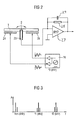
- FIG. 2 is a schematic of the vibrational gyroscope having the components needed to remove signals
- FIG. 3 is a spectrum of the signals applied to the fixed connection of the vibrational gyroscope
- FIG. 4 is a block diagram of an arrangement according to the invention.
- FIGS. 5 a - 5 d are voltage timing diagrams for different signals which occur in the arrangement according to FIG. 4 .
- the vibrational gyroscope illustrated in FIG. 1 comprises a disk 1 which is mounted such that it can be tilted at 2 but cannot be rotated.
- a ring 3 is connected to the disk 1 via resilient tongues 4 in such a manner that it can be made to vibrate rotationally with respect to the disk 1 .
- a plurality of arms 5 to 10 having capacitive elements 11 to 16 are situated on the circumference of the ring 3 .
- the arms 5 to 10 are illustrated in lengthened form in comparison with an exemplary embodiment.
- the capacitive elements 11 to 16 each comprise electrodes 17 , which are arranged on the arm and can therefore be moved with the ring 3 , and fixed electrodes 18 , 18 ′.
- the fixed electrodes 18 , 18 ′ are applied, such that they are insulated, to a substrate (not illustrated) that integrally includes elements 1 to 17 .
- Methods for patterning the substrate are known in the art and do not need to be discussed in any more detail in connection with the invention.
- the electrodes 18 , 18 ′ of the capacitive elements 11 to 14 are supplied with AC voltages at the same frequency but with a different phase angle for the purpose of exciting the rotational vibration referred to as the excitation voltage below.
- a DC voltage is respectively superposed on the excitation voltages, with the result that the electrodes 18 and the electrodes 18 ′ have the same DC voltage components and antiphase AC voltage components. This is effected in order to generate a periodic total torque because the torque generated at the electrode 18 , for example, is proportional to the square of the voltage applied there and is thus always positive. Only the sum of the two torques, which are generated by the electrodes 18 and 18 ′, contains the desired AC component.
- the electrodes 17 are interleaved with the electrodes 18 , 18 ′ in a comb-like manner. While only two individual electrodes are respectively illustrated for the sake of clarity, the number of electrodes is typically considerably higher.
- a frequency-controlled oscillator (VCO) 19 having two antiphase outputs 20 , 21 is used to generate antiphase excitation voltages which, provided with corresponding bias voltages, are supplied to the capacitive elements 11 to 13 .
- the connection 2 which is explained in more detail below in connection with the operation of obtaining the rate of rotation signal is used to feed back (not illustrated) the currents generated by the excitation voltages.
- the capacitive measuring elements 15 , 16 are used to regulate the rotational vibration, AC voltages which are generated in an oscillator 22 and are at a first measuring frequency f 1 being applied to said measuring elements. As likewise explained below, the operation of supplying these AC voltages is used to measure the capacitance of the capacitive elements 15 , 16 and thus to obtain a signal which represents the rotational vibration.
- FIG. 2 shows a side view of the disk 1 and its mounting 2 with the common connection 23 .
- the movement illustrated by a double-headed arrow is caused by the Coriolis force and represents the rate of rotation to be measured.
- the tilting movement is determined by measuring the capacitance and antiphase AC voltages generated by an oscillator 26 at a second measuring frequency f 2 applied to two electrodes 24 , 25 .
- the fixed connection 23 is connected to the input of an amplifier 27 which has feedback via a resistor 28 and a capacitor 29 and represents a form of charge amplifier.
- the signal at the connection 23 has the spectrum indicated in FIG. 3 .
- Components at the excitation frequency (the resonant frequency, fres in the example illustrated) are at twice the excitation frequency (2 fres) produced as a result of the capacitance oscillation and excitation voltage being mixed, at the first measuring frequency f 1 and at the second measuring frequency f 2 .
- the measuring frequencies have sidebands comprising the measuring information.
- the components at the frequencies fres and 2 ⁇ fres may give rise to considerable overdriving and interference that is largely suppressed by the sign-alternating driving in the four drive groups.
- the capacitive elements 11 to 14 and 15 , 16 are illustrated independently of their mechanical design, in comparison with FIG. 1 , with the result that the electrodes 18 and 18 ′, together with the electrodes 17 , respectively constitute a pair of capacitors, only two pairs of capacitors are illustrated instead of four pairs of capacitors 11 to 14 and only one pair of capacitors are illustrated instead of two pairs of capacitors 15 , 16 , for the sake of clarity.
- the charge amplification 27 at the output 23 and the subsequent bandpass filtering 30 have already been described in connection with FIGS. 2 and 3 .
- Two multipliers 31 , 32 in which synchronous demodulation using the measuring frequencies f 1 and f 2 is carried out are connected to the output A of the filter 30 .
- the demodulated signals are denoted using B and C.
- a signal which represents the rotational oscillation of the vibrational gyroscope is present at 34 .
- This signal is supplied to a further multiplier 35 which forms a control loop together with a regulator 36 having a characteristic F(p) and the oscillator 19 .
- the signal at 34 is compared with a reference voltage Uref using an adder 37 and is supplied to a control input of the oscillator 19 via a further regulator 38 with the characteristic G(p).
- the excitation voltage provided with a DC voltage component being present at the outputs 20 , 21 of said oscillator.
- the output signal C from the multiplier 32 is passed to a low-pass filter 39 . From there, the signal passes to a further multiplier 40 which is also supplied with a signal at the frequency fres, as a result of which said multiplier operates as a synchronous demodulator.
- the demodulated signal D represents the rate of rotation signal which is passed to an output 42 via an amplifier 41 .
- FIG. 5 shows different timing diagrams, namely a diagram A which illustrates the output signal A from the filter 30 , a diagram B which illustrates the output signal B from the synchronous demodulator 31 , a diagram C containing the output signal C from the synchronous demodulator 32 , and a diagram D containing the output signal D from the synchronous demodulator 40 , the carrier also being illustrated in addition to the envelope, namely the result of the demodulation, in order to illustrate the demodulation in the diagrams B, C and D.
Abstract
Description
- U1=U10+U11 sin ωt
- U2=U10−U11 sin ωt
- U3=−U1
- U4=−U2
Claims (11)
Applications Claiming Priority (4)
| Application Number | Priority Date | Filing Date | Title |
|---|---|---|---|
| DE102006046772A DE102006046772A1 (en) | 2006-09-29 | 2006-09-29 | Rotating rate measuring arrangement, has capacitive units formed by fixed electrodes and by other electrodes that are connected with fixed connection, where exciting voltages are supplied to fixed electrodes of capacitive units |
| DE102006046772 | 2006-09-29 | ||
| DE10-2006-046-772.8 | 2006-09-29 | ||
| PCT/EP2007/059607 WO2008040616A1 (en) | 2006-09-29 | 2007-09-13 | Arrangement for measuring a rate of rotation using a vibration sensor |
Publications (2)
| Publication Number | Publication Date |
|---|---|
| US20100011857A1 US20100011857A1 (en) | 2010-01-21 |
| US8042393B2 true US8042393B2 (en) | 2011-10-25 |
Family
ID=38805571
Family Applications (1)
| Application Number | Title | Priority Date | Filing Date |
|---|---|---|---|
| US12/443,664 Expired - Fee Related US8042393B2 (en) | 2006-09-29 | 2007-09-13 | Arrangement for measuring a rate of rotation using a vibration sensor |
Country Status (8)
| Country | Link |
|---|---|
| US (1) | US8042393B2 (en) |
| EP (1) | EP2087315B1 (en) |
| JP (1) | JP2010505102A (en) |
| KR (1) | KR101437190B1 (en) |
| CN (1) | CN101589292B (en) |
| DE (1) | DE102006046772A1 (en) |
| TW (1) | TWI427272B (en) |
| WO (1) | WO2008040616A1 (en) |
Cited By (4)
| Publication number | Priority date | Publication date | Assignee | Title |
|---|---|---|---|---|
| US20110048130A1 (en) * | 2008-03-03 | 2011-03-03 | Ramot At Tel-Aviv University Ltd. | Micro Scale Mechanical Rate Sensors |
| US20120096943A1 (en) * | 2010-10-25 | 2012-04-26 | Rosemount Aerospace Inc. | Mems gyros with quadrature reducing springs |
| US9052194B2 (en) | 2009-09-11 | 2015-06-09 | Invensense, Inc. | Extension-mode angular velocity sensor |
| US9097524B2 (en) | 2009-09-11 | 2015-08-04 | Invensense, Inc. | MEMS device with improved spring system |
Families Citing this family (20)
| Publication number | Priority date | Publication date | Assignee | Title |
|---|---|---|---|---|
| US8042394B2 (en) | 2007-09-11 | 2011-10-25 | Stmicroelectronics S.R.L. | High sensitivity microelectromechanical sensor with rotary driving motion |
| DE102008002748A1 (en) * | 2008-06-27 | 2009-12-31 | Sensordynamics Ag | Microgyroscope |
| US20110185829A1 (en) * | 2008-08-06 | 2011-08-04 | Pioneer Corporation | Rotational vibration gyro |
| ITTO20090489A1 (en) | 2008-11-26 | 2010-12-27 | St Microelectronics Srl | READING CIRCUIT FOR A MULTI-AXIS MEMS GYROSCOPE WITH DETECTED DETECTION DIRECTIONS COMPARED TO THE REFERENCE AXES, AND CORRESPONDING MEMS MULTI-AXIS GIROSCOPE |
| IT1391973B1 (en) | 2008-11-26 | 2012-02-02 | St Microelectronics Rousset | MONO OR BIASSIAL MICROELECTROMECHANICAL GYROSCOPE WITH INCREASED SENSITIVITY TO THE ANGULAR SPEED DETECTION |
| IT1391972B1 (en) * | 2008-11-26 | 2012-02-02 | St Microelectronics Rousset | MICROELETTROMECHANICAL GYROSCOPE WITH ROTARY DRIVE MOVEMENT AND IMPROVED ELECTRICAL CHARACTERISTICS |
| IT1392741B1 (en) | 2008-12-23 | 2012-03-16 | St Microelectronics Rousset | MICROELETTROMECHANICAL GYROSCOPE WITH IMPROVED REJECTION OF ACCELERATION DISORDERS |
| IT1394007B1 (en) | 2009-05-11 | 2012-05-17 | St Microelectronics Rousset | MICROELETTROMECANICAL STRUCTURE WITH IMPROVED REJECTION OF ACCELERATION DISORDERS |
| ITTO20091042A1 (en) | 2009-12-24 | 2011-06-25 | St Microelectronics Srl | MICROELETTROMECHANICAL INTEGRATED GYROSCOPE WITH IMPROVED DRIVE STRUCTURE |
| DE102010005231A1 (en) * | 2010-01-21 | 2011-07-28 | M & FC Holding LLC, N.C. | Method for detecting the rotations of a rotor |
| KR101012097B1 (en) * | 2010-04-12 | 2011-02-07 | 금오기전 주식회사 | Axial vibration measuring device of diesel engin crank shaft of ship using non-contact type sensor and measuring method of axial vibration using that |
| TWI426232B (en) * | 2010-10-12 | 2014-02-11 | Univ Nat Taiwan | Inertia sensing device and using method thereof |
| KR101306877B1 (en) * | 2011-01-26 | 2013-09-10 | 주식회사 유비트로닉스 | Tuning fork type gyroscope having internal sensing electrode |
| ITTO20110806A1 (en) | 2011-09-12 | 2013-03-13 | St Microelectronics Srl | MICROELETTROMECANICAL DEVICE INTEGRATING A GYROSCOPE AND AN ACCELEROMETER |
| US9099982B2 (en) * | 2012-01-25 | 2015-08-04 | International Business Machines Corporation | Method of manufacturing switching filters and design structures |
| KR20130098059A (en) * | 2012-02-27 | 2013-09-04 | 삼성전기주식회사 | Inertial sensor |
| US20140013845A1 (en) * | 2012-07-13 | 2014-01-16 | Robert E. Stewart | Class ii coriolis vibratory rocking mode gyroscope with central fixed post |
| US9404747B2 (en) | 2013-10-30 | 2016-08-02 | Stmicroelectroncs S.R.L. | Microelectromechanical gyroscope with compensation of quadrature error drift |
| DE102017215503A1 (en) * | 2017-09-05 | 2019-03-07 | Robert Bosch Gmbh | Micromechanical rotation rate sensor arrangement and corresponding production method |
| CN116147600A (en) * | 2021-10-27 | 2023-05-23 | 苏州明皜传感科技股份有限公司 | Micro electromechanical multi-axis angular velocity sensor |
Citations (12)
| Publication number | Priority date | Publication date | Assignee | Title |
|---|---|---|---|---|
| US4744249A (en) * | 1985-07-25 | 1988-05-17 | Litton Systems, Inc. | Vibrating accelerometer-multisensor |
| US4744248A (en) * | 1985-07-25 | 1988-05-17 | Litton Systems, Inc. | Vibrating accelerometer-multisensor |
| US5604311A (en) * | 1995-06-07 | 1997-02-18 | Litton Systems, Inc. | Coriolis effect rotation rate sensor and method |
| WO1998015799A1 (en) | 1996-10-07 | 1998-04-16 | HAHN-SCHICKARD-GESELLSCHAFT FÜR ANGEWANDTE FORSCHUNG E.V. Wilhelm-Schickard-Strasse 10 | Rotation rate sensor with uncoupled mutually perpendicular primary and secondary oscillations |
| US5955668A (en) | 1997-01-28 | 1999-09-21 | Irvine Sensors Corporation | Multi-element micro gyro |
| US6067858A (en) | 1996-05-31 | 2000-05-30 | The Regents Of The University Of California | Micromachined vibratory rate gyroscope |
| DE10006933A1 (en) | 1999-06-04 | 2000-12-14 | Samsung Electro Mech | Micro-gyroscope with inner and outer frames with means enabling the gyroscope to be set in stable resonance and which can be produced sufficiently cheaply so that it can be used in widespread applications such as household electronics |
| US6626039B1 (en) | 1999-09-17 | 2003-09-30 | Millisensor Systems And Actuators, Inc. | Electrically decoupled silicon gyroscope |
| US6686807B1 (en) | 1999-11-02 | 2004-02-03 | Eta Sa Fabriques D'ebauches | Time base comprising an integrated micromechanical ring resonator |
| US20050081633A1 (en) * | 2003-10-20 | 2005-04-21 | Nasiri Steven S. | X-y axis dual-mass tuning fork gyroscope with vertically integrated electronics and wafer-scale hermetic packaging |
| WO2005062754A2 (en) | 2003-12-04 | 2005-07-14 | The Regents Of University Of California | Micromachined gyroscope for simultaneously and directly measuring angular position and angular velocity |
| US20060156815A1 (en) | 2003-11-04 | 2006-07-20 | Shyu-Mou Chen | Solid-state gyroscopes and planar three-axis inertial measurement unit |
Family Cites Families (11)
| Publication number | Priority date | Publication date | Assignee | Title |
|---|---|---|---|---|
| JPS6358111A (en) * | 1986-08-27 | 1988-03-12 | Japan Storage Battery Co Ltd | Tuning fork type piezo-electric angular velocity sensor |
| JPS63241308A (en) * | 1987-03-30 | 1988-10-06 | Hitachi Ltd | Angular velocity sensor |
| MY120887A (en) * | 1995-06-08 | 2005-12-30 | Sony Corp | Rotation position detecting device and motor device. |
| EP1023607A2 (en) * | 1997-10-14 | 2000-08-02 | Irvine Sensors Corporation | Multi-element micro gyro |
| EP0953823A2 (en) * | 1998-05-01 | 1999-11-03 | Aisin Cosmos R & D Co. Ltd. | Micro yaw rate sensors |
| JP3489534B2 (en) * | 2000-04-20 | 2004-01-19 | トヨタ自動車株式会社 | Sensor device and sensor element |
| JP2003276000A (en) * | 2002-03-25 | 2003-09-30 | Murata Mfg Co Ltd | Bonded microstructure |
| JP3874707B2 (en) * | 2002-08-08 | 2007-01-31 | 株式会社デンソー | Starter |
| JP4433747B2 (en) * | 2003-09-29 | 2010-03-17 | 株式会社村田製作所 | Angular velocity detector |
| JP4381354B2 (en) * | 2004-09-10 | 2009-12-09 | セイコーエプソン株式会社 | Vibrator support structure and physical quantity measuring device |
| CN100480629C (en) * | 2005-10-24 | 2009-04-22 | 西北工业大学 | Capacitive micro machinery gyroscope |
-
2006
- 2006-09-29 DE DE102006046772A patent/DE102006046772A1/en not_active Withdrawn
-
2007
- 2007-09-13 CN CN2007800364788A patent/CN101589292B/en not_active Expired - Fee Related
- 2007-09-13 KR KR1020097008752A patent/KR101437190B1/en active IP Right Grant
- 2007-09-13 JP JP2009529651A patent/JP2010505102A/en active Pending
- 2007-09-13 US US12/443,664 patent/US8042393B2/en not_active Expired - Fee Related
- 2007-09-13 WO PCT/EP2007/059607 patent/WO2008040616A1/en active Application Filing
- 2007-09-13 EP EP07820163.9A patent/EP2087315B1/en not_active Not-in-force
- 2007-09-29 TW TW096136506A patent/TWI427272B/en not_active IP Right Cessation
Patent Citations (17)
| Publication number | Priority date | Publication date | Assignee | Title |
|---|---|---|---|---|
| US4744248A (en) * | 1985-07-25 | 1988-05-17 | Litton Systems, Inc. | Vibrating accelerometer-multisensor |
| US4744249A (en) * | 1985-07-25 | 1988-05-17 | Litton Systems, Inc. | Vibrating accelerometer-multisensor |
| US5604311A (en) * | 1995-06-07 | 1997-02-18 | Litton Systems, Inc. | Coriolis effect rotation rate sensor and method |
| US6067858A (en) | 1996-05-31 | 2000-05-30 | The Regents Of The University Of California | Micromachined vibratory rate gyroscope |
| DE69735759T2 (en) | 1996-05-31 | 2006-11-02 | The Regents Of The University Of California, Oakland | MICRO-MANUFACTURED VIBRATION SPEED CIRCUIT |
| US6561029B2 (en) | 1996-10-07 | 2003-05-13 | Hahn-Schickard-Gesellschaft Fur Angewandte Forschung E.V. | Rotational rate gyroscope with decoupled orthogonal primary and secondary oscillations |
| WO1998015799A1 (en) | 1996-10-07 | 1998-04-16 | HAHN-SCHICKARD-GESELLSCHAFT FÜR ANGEWANDTE FORSCHUNG E.V. Wilhelm-Schickard-Strasse 10 | Rotation rate sensor with uncoupled mutually perpendicular primary and secondary oscillations |
| US5955668A (en) | 1997-01-28 | 1999-09-21 | Irvine Sensors Corporation | Multi-element micro gyro |
| US6327907B1 (en) | 1999-06-04 | 2001-12-11 | Samsung Electro-Mechanics Co., Ltd. | Microgyroscope having asymmetric comb sensors |
| DE10006933A1 (en) | 1999-06-04 | 2000-12-14 | Samsung Electro Mech | Micro-gyroscope with inner and outer frames with means enabling the gyroscope to be set in stable resonance and which can be produced sufficiently cheaply so that it can be used in widespread applications such as household electronics |
| US6626039B1 (en) | 1999-09-17 | 2003-09-30 | Millisensor Systems And Actuators, Inc. | Electrically decoupled silicon gyroscope |
| US6686807B1 (en) | 1999-11-02 | 2004-02-03 | Eta Sa Fabriques D'ebauches | Time base comprising an integrated micromechanical ring resonator |
| DE60012217T2 (en) | 1999-11-02 | 2005-08-18 | Eta Sa Manufacture Horlogère Suisse | TIME REFERENCE WITH AN INTEGRATED MICROMECHANICAL RINGING RESONATOR |
| US20050081633A1 (en) * | 2003-10-20 | 2005-04-21 | Nasiri Steven S. | X-y axis dual-mass tuning fork gyroscope with vertically integrated electronics and wafer-scale hermetic packaging |
| US20060156815A1 (en) | 2003-11-04 | 2006-07-20 | Shyu-Mou Chen | Solid-state gyroscopes and planar three-axis inertial measurement unit |
| WO2005062754A2 (en) | 2003-12-04 | 2005-07-14 | The Regents Of University Of California | Micromachined gyroscope for simultaneously and directly measuring angular position and angular velocity |
| US7040164B2 (en) | 2003-12-04 | 2006-05-09 | The Regents Of The University Of California | Method of simultaneously and directly generating an angular position and angular velocity measurement in a micromachined gyroscope |
Cited By (9)
| Publication number | Priority date | Publication date | Assignee | Title |
|---|---|---|---|---|
| US20110048130A1 (en) * | 2008-03-03 | 2011-03-03 | Ramot At Tel-Aviv University Ltd. | Micro Scale Mechanical Rate Sensors |
| US8479574B2 (en) * | 2008-03-03 | 2013-07-09 | Ramot At Tel-Aviv University Ltd. | Micro scale mechanical rate sensors |
| US9052194B2 (en) | 2009-09-11 | 2015-06-09 | Invensense, Inc. | Extension-mode angular velocity sensor |
| US9097524B2 (en) | 2009-09-11 | 2015-08-04 | Invensense, Inc. | MEMS device with improved spring system |
| US9683844B2 (en) | 2009-09-11 | 2017-06-20 | Invensense, Inc. | Extension-mode angular velocity sensor |
| US9891053B2 (en) | 2009-09-11 | 2018-02-13 | Invensense, Inc. | MEMS device with improved spring system |
| US10551193B2 (en) | 2009-09-11 | 2020-02-04 | Invensense, Inc. | MEMS device with improved spring system |
| US20120096943A1 (en) * | 2010-10-25 | 2012-04-26 | Rosemount Aerospace Inc. | Mems gyros with quadrature reducing springs |
| US8539832B2 (en) * | 2010-10-25 | 2013-09-24 | Rosemount Aerospace Inc. | MEMS gyros with quadrature reducing springs |
Also Published As
| Publication number | Publication date |
|---|---|
| CN101589292B (en) | 2013-05-29 |
| EP2087315B1 (en) | 2017-07-12 |
| CN101589292A (en) | 2009-11-25 |
| WO2008040616A1 (en) | 2008-04-10 |
| JP2010505102A (en) | 2010-02-18 |
| KR20090074788A (en) | 2009-07-07 |
| KR101437190B1 (en) | 2014-09-03 |
| EP2087315A1 (en) | 2009-08-12 |
| TWI427272B (en) | 2014-02-21 |
| US20100011857A1 (en) | 2010-01-21 |
| TW200834039A (en) | 2008-08-16 |
| DE102006046772A1 (en) | 2008-04-03 |
Similar Documents
| Publication | Publication Date | Title |
|---|---|---|
| US8042393B2 (en) | Arrangement for measuring a rate of rotation using a vibration sensor | |
| AU2003223779B2 (en) | Pulse width modulation drive signal for a mems gyroscope | |
| US9869552B2 (en) | Gyroscope that compensates for fluctuations in sensitivity | |
| US5806364A (en) | Vibration-type angular velocity detector having sensorless temperature compensation | |
| US7779688B2 (en) | Vibration gyro sensor | |
| EP1723389B1 (en) | Error correction for vibratory rate gyroscope | |
| JP4690652B2 (en) | Micro electro mechanical system | |
| US5530342A (en) | Micromachined rate sensor comb drive device and method | |
| US5481914A (en) | Electronics for coriolis force and other sensors | |
| KR100592985B1 (en) | Vibration type angular velocity sensor | |
| EP2466257A1 (en) | Method for matching the natural frequencies of the drive and sense oscillators in a vibrating coriolis gyroscope | |
| JP2003507728A (en) | Apparatus for generating bias voltage for vibrating rotation angle rate sensor | |
| JPH08247772A (en) | Method and device for compensating micromachined sensor | |
| US7107841B2 (en) | Capacitance-sensing vibratory gyro and method for detecting change in capacitance | |
| JP3223156B2 (en) | Vibratory rotation sensor, method for controlling and reading out the same, and apparatus for performing the method | |
| EP3301398B1 (en) | A mems gyroscope having a high stability with respect to temperature and humidity variations | |
| JP5618101B2 (en) | Vibration gyro sensor | |
| GB2424706A (en) | Solid-state gyroscopes | |
| US11274925B2 (en) | Readout circuit for a MEMS gyroscope and method for operating such a readout circuit | |
| JP2011002295A (en) | Angular velocity detection device | |
| JP2548679B2 (en) | Vibrating gyroscope | |
| EP2040032A1 (en) | Improvements in or relating to angular velocity sensors | |
| JPH09105637A (en) | Vibrating gyro | |
| WO2023026470A1 (en) | Magnetic field sensor and magnetic field detection method | |
| KR100585893B1 (en) | A micro gyroscope and a method for tuning the Q-factor thereof |
Legal Events
| Date | Code | Title | Description |
|---|---|---|---|
| AS | Assignment |
Owner name: CONTINENTAL AUTOMOTIVE GMBH,GERMANY Free format text: ASSIGNMENT OF ASSIGNORS INTEREST;ASSIGNORS:GIER, LOTHAR;KEMPE, VOLKER;STRLE, DRAGO;SIGNING DATES FROM 20090310 TO 20090403;REEL/FRAME:022588/0884 Owner name: SENSORDYNAMICS AG,AUSTRIA Free format text: ASSIGNMENT OF ASSIGNORS INTEREST;ASSIGNORS:GIER, LOTHAR;KEMPE, VOLKER;STRLE, DRAGO;SIGNING DATES FROM 20090310 TO 20090403;REEL/FRAME:022588/0884 Owner name: CONTINENTAL AUTOMOTIVE GMBH, GERMANY Free format text: ASSIGNMENT OF ASSIGNORS INTEREST;ASSIGNORS:GIER, LOTHAR;KEMPE, VOLKER;STRLE, DRAGO;SIGNING DATES FROM 20090310 TO 20090403;REEL/FRAME:022588/0884 Owner name: SENSORDYNAMICS AG, AUSTRIA Free format text: ASSIGNMENT OF ASSIGNORS INTEREST;ASSIGNORS:GIER, LOTHAR;KEMPE, VOLKER;STRLE, DRAGO;SIGNING DATES FROM 20090310 TO 20090403;REEL/FRAME:022588/0884 |
|
| FEPP | Fee payment procedure |
Free format text: PAYOR NUMBER ASSIGNED (ORIGINAL EVENT CODE: ASPN); ENTITY STATUS OF PATENT OWNER: LARGE ENTITY |
|
| STCF | Information on status: patent grant |
Free format text: PATENTED CASE |
|
| FPAY | Fee payment |
Year of fee payment: 4 |
|
| FEPP | Fee payment procedure |
Free format text: MAINTENANCE FEE REMINDER MAILED (ORIGINAL EVENT CODE: REM.); ENTITY STATUS OF PATENT OWNER: LARGE ENTITY |
|
| LAPS | Lapse for failure to pay maintenance fees |
Free format text: PATENT EXPIRED FOR FAILURE TO PAY MAINTENANCE FEES (ORIGINAL EVENT CODE: EXP.); ENTITY STATUS OF PATENT OWNER: LARGE ENTITY |
|
| STCH | Information on status: patent discontinuation |
Free format text: PATENT EXPIRED DUE TO NONPAYMENT OF MAINTENANCE FEES UNDER 37 CFR 1.362 |
|
| FP | Lapsed due to failure to pay maintenance fee |
Effective date: 20191025 |