US8038113B2 - Telescoping mounting system for a recessed luminaire - Google Patents
Telescoping mounting system for a recessed luminaire Download PDFInfo
- Publication number
- US8038113B2 US8038113B2 US12/726,956 US72695610A US8038113B2 US 8038113 B2 US8038113 B2 US 8038113B2 US 72695610 A US72695610 A US 72695610A US 8038113 B2 US8038113 B2 US 8038113B2
- Authority
- US
- United States
- Prior art keywords
- mounting
- pair
- bar
- bars
- telescoping
- Prior art date
- Legal status (The legal status is an assumption and is not a legal conclusion. Google has not performed a legal analysis and makes no representation as to the accuracy of the status listed.)
- Active, expires
Links
Images


Classifications
-
- F—MECHANICAL ENGINEERING; LIGHTING; HEATING; WEAPONS; BLASTING
- F21—LIGHTING
- F21S—NON-PORTABLE LIGHTING DEVICES; SYSTEMS THEREOF; VEHICLE LIGHTING DEVICES SPECIALLY ADAPTED FOR VEHICLE EXTERIORS
- F21S8/00—Lighting devices intended for fixed installation
- F21S8/02—Lighting devices intended for fixed installation of recess-mounted type, e.g. downlighters
- F21S8/026—Lighting devices intended for fixed installation of recess-mounted type, e.g. downlighters intended to be recessed in a ceiling or like overhead structure, e.g. suspended ceiling
-
- F—MECHANICAL ENGINEERING; LIGHTING; HEATING; WEAPONS; BLASTING
- F21—LIGHTING
- F21V—FUNCTIONAL FEATURES OR DETAILS OF LIGHTING DEVICES OR SYSTEMS THEREOF; STRUCTURAL COMBINATIONS OF LIGHTING DEVICES WITH OTHER ARTICLES, NOT OTHERWISE PROVIDED FOR
- F21V21/00—Supporting, suspending, or attaching arrangements for lighting devices; Hand grips
- F21V21/02—Wall, ceiling, or floor bases; Fixing pendants or arms to the bases
- F21V21/04—Recessed bases
- F21V21/048—Mounting arrangements for fastening lighting devices to false ceiling frameworks
-
- Y—GENERAL TAGGING OF NEW TECHNOLOGICAL DEVELOPMENTS; GENERAL TAGGING OF CROSS-SECTIONAL TECHNOLOGIES SPANNING OVER SEVERAL SECTIONS OF THE IPC; TECHNICAL SUBJECTS COVERED BY FORMER USPC CROSS-REFERENCE ART COLLECTIONS [XRACs] AND DIGESTS
- Y10—TECHNICAL SUBJECTS COVERED BY FORMER USPC
- Y10S—TECHNICAL SUBJECTS COVERED BY FORMER USPC CROSS-REFERENCE ART COLLECTIONS [XRACs] AND DIGESTS
- Y10S248/00—Supports
- Y10S248/906—Electrical outlet box support
Definitions
- This invention is directed generally to mountings systems, and, more particularly, to a telescoping system for mounting a recessed luminaire to a building structure.
- a recessed luminaire also referred to as a light fixture
- a recessed luminaire is secured to wood and/or steel framing of a building using telescoping bars that cover common spacing between parallel framing members.
- the telescoping bars cover a joist spacing in the range of about 16 inches-24 inches or a T-bar spacing in the range of about 24 inches.
- the recessed luminaire After attachment to the building framing, the recessed luminaire can be adjusted perpendicular to the framing members by sliding it along the telescoping bars.
- the telescoping bars generally require two distinct members—a male member and a female member—to form a telescoping assembly.
- having to manufacture and install two separate components (i.e., members) for the telescoping assemblies unnecessarily increases tooling expenditure, components cost, and inventory handling.
- usage of present telescoping assemblies results in decreased profits and operations efficiency.
- typical telescoping bars tend to have cross-sectional shapes of low strength and rigidity.
- some telescoping bars have a generally U-shape that tends to flex in an impeding manner (e.g., in a direction perpendicular to the adjustment direction) when attempting to adjust the telescoping bars.
- typical telescoping bars are manufactured using processes that result in scrap material, resulting in material waste and increased manufacturing costs.
- Certain telescoping assemblies also include free-sliding components that facilitate a sliding (or telescoping) motion of the telescoping bars.
- the free-sliding components have the potential to cause binding, damage, and/or injury during the handling, installation, and/or adjustment of the telescoping bars.
- the free-sliding components tend to increase the perception that the telescoping assembly is made of poor quality.
- Some telescoping assemblies also include mounting feet having joist alignment flanges for aiding in aligning the telescoping assembly to the framing members during the installation procedure.
- end users commonly complain that these joist alignment flanges interfere with adjacent ceiling tiles.
- Such devices may include audio speakers, recessed fans, electrical boxes, etc.
- a telescoping mounting system improves installation and adjustment between a recessed luminaire and a framing structure.
- the mounting system includes two telescoping bars having a generally identical S-shaped cross-sectional profile.
- the S-shaped profile allows both telescoping bars to function as either the “male” member or the “female” member of the mounting system by simply changing the orientation of the telescoping bars. For example, with both telescoping bars being in identical positions, one of the bars is rotated 180° about a horizontal axis to facilitate engagement between the bars.
- the telescoping bars can be manufactured using a cold rolling process to eliminate scrap material.
- the mounting system further includes a plurality of mounting guides molded from a plastic material and having a geometry designed to clamp tightly around the telescoping bars and secure each mounting guide to a plaster frame.
- Each of the mounting guides has two opposing sides connected by a flexible hinge, which allows a snapping connection of the mounting guides to the plaster frame.
- Each of the opposing sides has an internal surface that interfaces with the S-shaped bars.
- the mounting system includes mounting feet attached to the end of the S-shaped telescoping bars.
- the mounting feet include one or more features directed to improving functionality, especially when they are mounted to a T-bar grid ceiling.
- the features include one or more supplemental locking features that prevent unintentional or undesired detachment from the framing structure; features that allow easy field removal of areas of the mounting feet that can interfere with adjacent ceiling tiles; a combination nail-form and T-bar clamp that improves the connection between the mounting feet and the T-bar; and/or anti-rotation features intended to prevent unintended rotational movement of the mounting feet when a surface of the alignment flange is not in intimate contact with a joist surface.
- a lighting assembly for a recessed luminaire includes a plaster frame for supporting the recessed luminaire and a pair of telescoping bars for attaching the plaster frame to framing support members.
- the telescoping bars include a first bar and a second bar, each of the bars having a generally S-shaped cross-sectional profile that is defined by a center curve joining a first area and a second area of the cross-sectional profile.
- the first area of the first bar is overlappingly positioned at least in part within the second area of the second bar, and the first area of the second bar is overlappingly positioned at least in part within the second area of the second bar.
- a lighting assembly for a recessed luminaire includes a plaster frame for supporting the recessed luminaire.
- the lighting assembly further includes four cutouts, including a first pair of attachments positioned along a first edge of the plaster frame and a second pair of attachments positioned along a second edge of the plaster frame.
- a first pair of mounting guides is secured correspondingly to the first pair of cutouts, and a second pair of mounting guides is secured correspondingly to the second pair of cutouts.
- Each of the mounting guides is made from a molded plastic material and includes a flexible hinge that joins two opposing parallel sides.
- a first pair of telescoping bars is slidably mounted to the plaster frame via the first pair of mounting guides, and a second pair of telescoping bars is slidably mounted to the plaster frame via the second pair of mounting guides.
- Each of the telescoping bars is identical to each other and has a generally S-shaped cross-sectional profile.
- a first pair of mounting feet is mounted correspondingly to each end of the first pair of telescoping bars, and a second pair of mounting feet is mounted correspondingly to each end of the second pair of telescoping bars.
- FIG. 1 is a partial top front perspective view of a recessed luminaire.
- FIG. 2A is a full bottom front perspective view of the recessed luminaire.
- FIG. 2B is a partial perspective of a plaster frame.
- FIG. 2C is a partial perspective of a mounting guide assembled to the plaster frame and to S-shaped telescoping bars.
- FIG. 3A is a perspective view of a first S-shaped telescoping bar.
- FIG. 3B is a perspective view of a second S-shaped telescoping bar.
- FIG. 3C is a side view showing assembled profile of the first and second S-shaped telescoping bars.
- FIG. 3D is a partial enlarged perspective view of the second S-shaped telescoping bar.
- FIG. 4A is perspective view of interior surfaces of a mounting guide.
- FIG. 4B is a perspective view of exterior surfaces of the mounting guide.
- FIG. 5A is a perspective view illustrating the mounting guide prior to being secured to the plaster frame.
- FIG. 5B is a perspective view illustrating the mounting guide after being secured to the plaster frame.
- FIG. 5C is a side view illustrating the mounting guide and the S-shaped telescoping bars assembled to the plaster frame.
- FIG. 6A is a front perspective view of a mounting foot.
- FIG. 6B is a back perspective view of the mounting foot.
- FIG. 7A is a lower front perspective view illustrating attachment of the mounting foot to a wood framing member.
- FIG. 7B is a front perspective view illustrating attachment of the mounting foot to a T-Bar framing member.
- FIG. 7C is an upper back perspective view illustrating the attachment of the mounting foot to the T-Bar framing member.
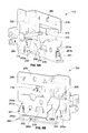
- a recessed fixture in the form of a recessed luminaire 100 includes a luminaire housing 102 and a mounting assembly including a plaster frame 104 and a pair of telescoping bars 106 .
- the recessed fixture can also be, for example, an audio speaker, an electrical fan, or an electrical box.
- the telescoping bars 106 are attached to the plaster frame 104 using a pair of mounting guides 108 .
- a locking screw 110 is used, generally, as a set screw to prevent motion of the bars 106 relative to the mounting guide 108 .
- the telescoping bars 106 are rigidly attachable to a building structure using a pair of mounting feet 112 , which are attached at each end of the telescoping bars 106 .
- the building structure typically includes structural framing members such as a wood framing member 310 a (shown in FIG. 7A ) and/or a steel framing member 310 b (shown in FIGS. 7B and 7C ).
- the framing members (collectively identified as framing members 310 ) are separated by a distance commonly referred to as a joist spacing (typical in wood framing members) or a T-Bar spacing (typical in steel framing members having a T-Bar cross-sectional shape).
- a fastener 114 Prior to installation of a finished ceiling (or other covering surface), is used to attach the mounting feet 112 to the framing members 310 .
- a typical assembly of the recessed luminaire 100 includes a total of two pairs of telescoping bars 106 (one pair per side), two pairs of mounting guides 108 (one pair per side), two pairs of mounting feet 112 (one pair per side), a single plaster frame 104 , and at least two locking screws 110 (at least one per side).
- the plaster frame 104 is a base support plate that can be an integral part of the recessed luminaire 100 or a separate removable part, and has a first edge 119 a and a second edge 119 b (which are generally parallel to each other).
- the plaster frame 104 can be constructed of formed sheet steel in various length and width combinations per the overall luminaire size requirements. The plaster frame is so called because it is typically adapted to receive plaster for finishing the ceiling surface once the recessed light fixture/luminaire and the ceiling plane have been installed.
- the plaster frame 104 is a generally rectangular plate having an embossed rib 120 for supporting the telescoping bars 106 .
- the embossed rib 120 is generally an indentation rising up from a generally flat area of the plaster frame 104 to make contact with the telescoping bars 106 .
- the embossed rib 120 is located along the first edge 119 a of the plaster frame 104 in a centrally located position.
- the plaster frame 104 has cutouts 122 for attachment of the mounting guides 108 .
- the cutouts 122 are located near each end of the first edge 119 a and have a size and shape adapted for receiving a respective mounting guide 108 .
- the plaster frame 104 includes a similar embossed rib and cutouts along the second edge 119 b.
- the telescoping bars 106 include a first bar 106 a and a second bar 106 b , each bar being identical to each other and having an S-shaped constant profile.
- the telescoping bars 106 are designed such that a single profile can be used two times in each telescoping assembly of bars 106 .
- the gender e.g., male/female or left/right
- the S-shaped bars 106 have the potential to reduce tooling expenditure, lower component costs, and reduce inventory handling, which can result in increased profits and improved efficiency in operations.
- S-shaped profile provides sufficient stiffness to eliminate undesirable vertical bending of the bars 106 .
- the description below will generally refer to a single bar (e.g., to the first bar 106 a ). However, it is understood that the description applies equally to both bars.
- the S-shaped profile is defined by a center curve 130 that joins a first area 132 with a second area 134 .
- the first area 132 of the first bar 106 a is overlappingly positioned at least in part within the second area 134 of the second bar 106 b
- the first area 132 of the second bar 106 b is overlappingly positioned at least in part within the second area 134 of the first bar 106 a.
- the first area 132 includes a first lateral side 136 that extends generally perpendicular away from a first end of the center curve 130 .
- the second area 134 includes a second lateral side 138 that extends generally perpendicular away from a second end of the center curve 130 .
- the second lateral side 138 extends in an opposite direction than the first lateral side 136 .
- the second end of the center curve 130 is opposite to the first end.
- the lateral sides 136 , 138 are each generally hook-shaped and join with the center curve 130 to form the general S-shape profile of the telescoping bars 106 .
- the first area 132 further includes a smaller C-shape profile 140 at the end of the first lateral side 136 and a larger C-shape profile 142 at the end of the second lateral side 138 .
- the smaller C-shape profile 140 of one bar fits within the larger C-shape profile 142 of another bar for telescoping movement of the telescoping bars 106 relative to each other.
- the smaller C-shape profile 140 slides along and within the larger C-shape profile 142 .
- the telescoping bar 106 a further includes at least one score line 150 and score notch 151 located transversally along the length of the bars 106 to allow shortening of the bars 106 when necessary.
- the score line 150 is a partially cut line of weakness on one side of the bars 106 that facilitates, along with the score notch 151 , easy removal (e.g., by manually bending and removing) of a sectional length 152 of the bars 106 .
- the telescoping bar 106 a is typically made from formed sheet steel and can have a length, thickness, and cross-sectional profile that can be changed to meet an end use application without affecting design intent.
- the telescoping bars 106 are preferably made from a cold-rolled steel material via a roll forming process because it eliminates generation of scrap material. For example, in contrast to a progressive die stamping process, roll forming does not require excess material to carry the telescoping bars 106 through a tool.
- the telescoping bar 106 a has a flat uninterrupted surface 154 for achieving a smooth feel with slight tension of the telescoping assembly.
- the smooth feel and slight tension is further achieved using formed left and right tabs 156 , 158 , respectively, in conjunction with left and right tab notches 160 , 162 .
- the tabs 156 , 158 are formed inward in a rectangular shape to provide tension between the assembled telescoping bars 106 , and to act in conjunction with a respective tab notch 160 , 162 (also rectangular in shape) to prevent disengagement of the telescoping bars 106 at the end of the bar span.
- a left tab 156 of the first telescoping bar 106 a is received within the left tab notch 160 of the second telescoping bar 106 b
- the right tab 158 of the first telescoping bar 106 a is received within the right tab notch 162 of the second telescoping bar 106 b.
- the telescoping bar 106 a further includes a plurality of holes 164 for mechanically securing the mounting feet 112 and indicator arrows 166 for correct alignment with the mounting feet 112 .
- the mounting guide 108 is made from a molded plastic material, which is preferably manufactured using an injection molding of a plastic material.
- the injection molding manufacturing process allows molding the unique geometry of the mounting guide 108 for interfacing with the S-shaped telescoping bars 106 and for combining several features into a single part. Furthermore, the use of a plastic material reduces friction and improves the sliding fit between the telescoping bars 106 and the molded mounting guide 108 .
- the mounting guide 108 includes a hinge 170 that flexibly connects a first hinge part 172 to a second hinge part 174 .
- the first part 172 has an internal central ridge 176 that separates a large mating surface 178 from a small mating surface 180 .
- the second part 174 has a similar internal central ridge 182 that separates a large mating surface 184 from a small mating surface 186 .
- the mating surfaces 178 , 180 , 184 , 186 slidably engage surfaces of the telescoping bars 106 .
- lead-in surfaces 188 - 191 are provided along each engaging edge of the first part 172 and lead-in surfaces 192 - 195 are provided along each engaging edge of the second part 174 .
- the lead-in surfaces 188 - 195 have a beveled shape for providing a smooth point of entry and mating interface between the telescoping bars 106 and the mounting guide 108 .
- the mounting guide 108 includes a release notch 196 , a locking screw boss 197 , a plaster frame clearance notch 198 , and a strengthening and attachment rib 199 .
- the release notch 196 is helpful in releasing or detaching the mounting guide 108 from the plaster frame 104 (if disassembly is required).
- a tool such as a screwdriver tip can be inserted into the release notch 196 to release the mounting guide 108 .
- the locking screw boss 197 is adapted to receive the locking screw 110 for locking in position movement of the telescoping bars 106 relative to the mounting guide 108 .
- the locking screw 110 protrudes within the mounting guide 108 through the locking screw boss 197 , the locking screw 110 makes contact with the telescoping bars 106 and applies a retaining frictional force to the telescoping bars 106 to prevent motion relative to the mounting guide 108 .
- the strengthening and attachment rib 199 provides rigidity to the mounting guide 108 , e.g., preventing or reducing unintended flexure of the mounting guide 108 .
- the mounting guide 108 further includes a pair of integral snaps 200 , 201 and a pair of snap catches 202 , 203 .
- the snaps 200 , 201 are positioned along a first frame surface 204 of the first part 172
- the snap catches 202 , 203 are positioned along a second frame surface 206 of the second part 174 .
- the snaps 200 , 201 , and the snap catches 202 , 203 fix the mounting guide 108 to the plaster frame 104 .
- the mounting guide 108 is mechanically attached to the plaster frame 104 by moving the first part 172 in parallel position with the second part 174 and inserting the snaps 200 , 201 into the snap catches 202 , 203 .
- the flexible hinge 170 allows the first part 172 to snap shut parallel to the second part 174 with the plaster frame 104 interposed between the first frame surface 204 of the first part 172 and the second frame surface 206 of the second part 174 .
- the mounting guide 108 is in a snapped closed position secured to the plaster frame 104 such that the first and second telescoping bars 106 a , 106 b are captured on four sides by the mounting guide 108 .
- the first and second telescoping bars 106 a , 106 b interface with the mounting guide 108 along the mating surfaces 178 , 180 , 184 , 186 (which are clearly displayed in FIG. 4A ), and the internal central ridges 176 , 182 interface respectively with the center curve 130 of the telescoping bars 106 .
- the locking screw 110 locks the telescoping bars 106 in position relative to the mounting guide 108 telescoping bars 106 , with the telescoping bars 106 being inserted within the mounting guide 108 .
- the interface between the mounting guide 108 and the telescoping bars 106 is advantageous because it maintains the luminaire in the same vertical position when adjusting along the span of the telescoping bars 106 and because it eliminates binding of the luminaire when transitioning from the first telescoping bar 106 a to the second telescoping bar 106 b (or vice versa).
- the interface eliminates undesirable vertical motion of the recessed luminaire 100 , which is common to various current products in the industry.
- the lead-in surfaces 188 - 195 are also helpful in easing transitioning from the first telescoping bar 106 a to the second telescoping bar 106 b (or vice versa) or when inserting the telescoping bars 106 for the first time.
- Another advantage of the interface between the mounting guide 108 and the telescoping bars 106 is that a slight amount of friction is provided between the mounting guide 108 and the telescoping bars 106 . This friction helps maintain the position of the telescoping bars 106 during handling and installation.
- a smooth-sliding (fluid) action is achieved between the first telescoping bar 106 a and the second telescoping bar 106 b , and between the telescoping bars 106 and the mounting guide 108 .
- This smooth-sliding action eliminates free-sliding components, which have the potential to cause binding, damage, and/or injury during handling, installation, and adjustment. Furthermore, the smooth-sliding action improves the perception of quality regarding the recessed luminaire 100 .
- the mounting foot 112 is manufactured from a sheet steel material and is mechanically attached to the ends of the telescoping bars 106 to facilitate securing the luminaire to the building structure.
- the mounting foot 112 has two locks 250 , 251 that include a lock slot 250 a , 251 a and a stepped surface 250 b , 251 b .
- a screwdriver tip can be inserted into the lock slot 250 a , 251 a to bend the lock 250 , 251 inwards such that the stepped surface 250 b , 251 b is firmly in contact with the T-Bar framing member 310 b .
- the locks 250 , 251 prevent detachment of the mounting foot 112 from the T-Bar framing member 310 b.
- the mounting foot 112 includes a break-away joist alignment flange 260 having a flange score line 260 a and a flange slot 260 b .
- the flange 260 can be removed from the mounting foot 112 by inserting a screwdriver tip into the flange slot 260 b and applying force. The applied forces separates the flange 260 from the mounting foot 112 along the flange score line 260 a .
- the flange 260 may be useful for alignment purposes when attaching the mounting foot 112 to a wood framing member 310 a , but may interfere with installation of ceiling tiles when attaching the mounting foot 112 to a T-Bar framing member.
- the flange 260 can be removed after attaching the mounting foot 112 to the T-Bar framing member 310 b ( FIG. 7B ).
- the mounting foot 112 includes a dual-attachment feature for attaching the mounting foot 112 to either a wood framing member 310 a ( FIG. 7A ) or a T-Bar framing member 310 b .
- the attachment feature is a nail form 270 ( FIG. 6A ) having a nail hole 272 and a clip tab 274 .
- the nail form 270 extends away from a main wall 276 of the mounting foot 112 .
- the fastener 114 is inserted through the nail hole 272 to secure in place the mounting foot 112 to a building structure, such as a wood framing member 310 a .
- the clip tab 274 overlaps a T-Bar type of framing member (shown in FIG. 7B ) to ease attachment and positioning of the mounting foot 112 relative to the framing member 310 .
- the mounting foot 112 includes a T-Bar clip 278 that extends inwards from the main wall 276 in the same direction as the nail form 270 .
- the T-Bar clip 278 is another feature that helps maintain the mounting foot 112 in position relative to a T-Bar framing member 310 b.
- the mounting foot 112 includes anti-rotation barbs 280 on an external (or back) surface of the main wall 276 .
- the anti-rotation barbs 280 are inserted into a wood framing member 310 a to prevent undesired rotation of the mounting foot 112 relative to the framing member 310 during and after driving the nail or screw.
- the anti-rotation barbs 280 provide a more secure and rigid installation of the recessed luminaire 100 .
- auxiliary mounting holes 300 auxiliary mounting holes 300 , strengthening features 302 , a telescoping bar alignment indicator 304 , a tension leg 306 (for T-Bar construction), a support leg 308 (for T-Bar construction).
- strengthening features 302 a telescoping bar alignment indicator 304
- tension leg 306 for T-Bar construction
- support leg 308 for T-Bar construction
- the mounting foot 112 can be attached to either the wood framing member 310 a or the T-Bar framing member 310 b .
- the features descried above facilitate attachment to either type of framing member, or to similar framing members.
Abstract
Description
Claims (20)
Priority Applications (3)
| Application Number | Priority Date | Filing Date | Title |
|---|---|---|---|
| US12/726,956 US8038113B2 (en) | 2010-03-18 | 2010-03-18 | Telescoping mounting system for a recessed luminaire |
| CA2734369A CA2734369C (en) | 2010-03-18 | 2011-03-17 | Telescoping mounting system for a recessed luminaire |
| MX2011002947A MX2011002947A (en) | 2010-03-18 | 2011-03-18 | Telescoping mounting system for a recessed luminaire. |
Applications Claiming Priority (1)
| Application Number | Priority Date | Filing Date | Title |
|---|---|---|---|
| US12/726,956 US8038113B2 (en) | 2010-03-18 | 2010-03-18 | Telescoping mounting system for a recessed luminaire |
Publications (2)
| Publication Number | Publication Date |
|---|---|
| US20110226919A1 US20110226919A1 (en) | 2011-09-22 |
| US8038113B2 true US8038113B2 (en) | 2011-10-18 |
Family
ID=44646477
Family Applications (1)
| Application Number | Title | Priority Date | Filing Date |
|---|---|---|---|
| US12/726,956 Active 2030-04-14 US8038113B2 (en) | 2010-03-18 | 2010-03-18 | Telescoping mounting system for a recessed luminaire |
Country Status (3)
| Country | Link |
|---|---|
| US (1) | US8038113B2 (en) |
| CA (1) | CA2734369C (en) |
| MX (1) | MX2011002947A (en) |
Cited By (48)
| Publication number | Priority date | Publication date | Assignee | Title |
|---|---|---|---|---|
| US20120317915A1 (en) * | 2011-06-16 | 2012-12-20 | Chicago Metallic Corporation | Self-Hanging Notched Ceiling Tile |
| US20140299730A1 (en) * | 2013-04-05 | 2014-10-09 | Russell Green | Adjustable Hanger Bar For Luminaires |
| US20140340882A1 (en) * | 2013-05-15 | 2014-11-20 | Tom Woods | Ballast adapter |
| US20140353442A1 (en) * | 2013-06-04 | 2014-12-04 | Thomas & Betts International Llc | Hanger Bar |
| US9004435B2 (en) | 2004-03-25 | 2015-04-14 | Cooper Technologies Company | Hanger bar for recessed luminaires with integral nail |
| US9060607B1 (en) | 2012-10-17 | 2015-06-23 | Cooper Technologies Company | Hanger bar for recessed light fixture mounting |
| US9239131B1 (en) | 2015-06-05 | 2016-01-19 | Cooper Technologies Company | Adjustable hanger bars with detachment stop |
| US9383087B2 (en) | 2014-03-05 | 2016-07-05 | Elite Lighting | Adjustable recessed light fixture |
| US20160209007A1 (en) * | 2015-01-19 | 2016-07-21 | John-Paul Belmonte | Pot light assembly |
| US9581302B2 (en) | 2012-05-31 | 2017-02-28 | Michael D. Danesh | Recessed lighting module with interchangeable trims |
| US9696021B2 (en) | 2004-03-25 | 2017-07-04 | Cooper Technologies Company | Hanger bar for recessed luminaires |
| US9732904B1 (en) | 2015-06-05 | 2017-08-15 | Cooper Technologies Company | Adjustable hanger bar assembly for luminaires |
| USD803459S1 (en) | 2013-04-22 | 2017-11-21 | Cooper Technologies Company | Edgelit garage luminaire |
| US9964266B2 (en) | 2013-07-05 | 2018-05-08 | DMF, Inc. | Unified driver and light source assembly for recessed lighting |
| USD833977S1 (en) | 2015-10-05 | 2018-11-20 | DMF, Inc. | Electrical junction box |
| US10139059B2 (en) | 2014-02-18 | 2018-11-27 | DMF, Inc. | Adjustable compact recessed lighting assembly with hangar bars |
| US20190090041A1 (en) * | 2017-09-20 | 2019-03-21 | Mitek Corp., Inc. | Adjustable speaker support for suspended ceilings |
| USD847414S1 (en) | 2015-05-29 | 2019-04-30 | DMF, Inc. | Lighting module |
| US20190277480A1 (en) * | 2018-03-08 | 2019-09-12 | Usai, Llc | Lighting System For Suspended Ceiling |
| USD864877S1 (en) | 2019-01-29 | 2019-10-29 | DMF, Inc. | Plastic deep electrical junction box with a lighting module mounting yoke |
| US10488000B2 (en) | 2017-06-22 | 2019-11-26 | DMF, Inc. | Thin profile surface mount lighting apparatus |
| US10551044B2 (en) | 2015-11-16 | 2020-02-04 | DMF, Inc. | Recessed lighting assembly |
| US10563850B2 (en) | 2015-04-22 | 2020-02-18 | DMF, Inc. | Outer casing for a recessed lighting fixture |
| US10584837B2 (en) | 2016-10-28 | 2020-03-10 | Cordelia Lighting, Inc. | Bar hanger system for recessed fixtures |
| US10663153B2 (en) | 2017-12-27 | 2020-05-26 | DMF, Inc. | Methods and apparatus for adjusting a luminaire |
| US10753558B2 (en) | 2013-07-05 | 2020-08-25 | DMF, Inc. | Lighting apparatus and methods |
| US10808401B2 (en) | 2017-06-09 | 2020-10-20 | Air Distribution Technologies Ip, Llc | Ceiling support systems |
| USD901398S1 (en) | 2019-01-29 | 2020-11-10 | DMF, Inc. | Plastic deep electrical junction box |
| USD902871S1 (en) | 2018-06-12 | 2020-11-24 | DMF, Inc. | Plastic deep electrical junction box |
| USD905327S1 (en) | 2018-05-17 | 2020-12-15 | DMF, Inc. | Light fixture |
| US10975570B2 (en) | 2017-11-28 | 2021-04-13 | DMF, Inc. | Adjustable hanger bar assembly |
| US11060705B1 (en) | 2013-07-05 | 2021-07-13 | DMF, Inc. | Compact lighting apparatus with AC to DC converter and integrated electrical connector |
| US11067231B2 (en) | 2017-08-28 | 2021-07-20 | DMF, Inc. | Alternate junction box and arrangement for lighting apparatus |
| US11231154B2 (en) * | 2018-10-02 | 2022-01-25 | Ver Lighting Llc | Bar hanger assembly with mating telescoping bars |
| US11255497B2 (en) | 2013-07-05 | 2022-02-22 | DMF, Inc. | Adjustable electrical apparatus with hangar bars for installation in a building |
| USD945054S1 (en) | 2017-06-22 | 2022-03-01 | DMF, Inc. | Light fixture |
| US11274821B2 (en) | 2019-09-12 | 2022-03-15 | DMF, Inc. | Lighting module with keyed heat sink coupled to thermally conductive trim |
| US11306903B2 (en) | 2020-07-17 | 2022-04-19 | DMF, Inc. | Polymer housing for a lighting system and methods for using same |
| US11342733B2 (en) | 2020-03-09 | 2022-05-24 | Erico International Corporation | Bracket system for mounting electrical boxes |
| US11349289B2 (en) | 2019-09-19 | 2022-05-31 | Erico International Corporation | Mounting bracket for electrical boxes |
| US11391442B2 (en) | 2018-06-11 | 2022-07-19 | DMF, Inc. | Polymer housing for a recessed lighting system and methods for using same |
| US11435064B1 (en) | 2013-07-05 | 2022-09-06 | DMF, Inc. | Integrated lighting module |
| USD966877S1 (en) | 2019-03-14 | 2022-10-18 | Ver Lighting Llc | Hanger bar for a hanger bar assembly |
| US11495952B2 (en) | 2019-09-18 | 2022-11-08 | Erico International Corporation | Bracket system for mounting electrical boxes |
| USD970081S1 (en) | 2018-05-24 | 2022-11-15 | DMF, Inc. | Light fixture |
| US11585517B2 (en) | 2020-07-23 | 2023-02-21 | DMF, Inc. | Lighting module having field-replaceable optics, improved cooling, and tool-less mounting features |
| USD990030S1 (en) | 2020-07-17 | 2023-06-20 | DMF, Inc. | Housing for a lighting system |
| USD1012864S1 (en) | 2019-01-29 | 2024-01-30 | DMF, Inc. | Portion of a plastic deep electrical junction box |
Families Citing this family (13)
| Publication number | Priority date | Publication date | Assignee | Title |
|---|---|---|---|---|
| CN103016925B (en) * | 2011-09-26 | 2016-03-23 | 广东松下环境系统有限公司 | For the mounting bracket of integrated ceiling appliance |
| US8763336B2 (en) * | 2012-03-01 | 2014-07-01 | Usg Interiors, Llc | Attachment clip for ceiling grid systems |
| WO2014028823A1 (en) * | 2012-08-16 | 2014-02-20 | Leading Energy Designs, Ltd. | Led bracket apparatus for high-output led lighting systems |
| KR101326041B1 (en) * | 2012-08-20 | 2013-11-07 | (주)에이스 힌지텍 | (a panel for hanging and device for hanging using the same |
| US10443824B2 (en) * | 2013-03-15 | 2019-10-15 | The Sloan Company, Inc. | Sign box lighting system |
| US10446065B2 (en) * | 2013-03-15 | 2019-10-15 | The Sloan Company, Inc. | Sign box lighting system |
| JP6342475B2 (en) | 2013-03-25 | 2018-06-13 | フィリップス ライティング ホールディング ビー ヴィ | Easy to install lighting fixtures |
| US10006613B2 (en) | 2016-04-20 | 2018-06-26 | Tripar Inc. | Bar hanger with substantially identical members for recessed luminaires |
| USD819879S1 (en) | 2017-02-09 | 2018-06-05 | Tripar Inc. | Bar hanger |
| US10237636B1 (en) * | 2017-09-20 | 2019-03-19 | Mitek Corp., Inc. | Small ceiling speaker system |
| CN111059443A (en) * | 2020-01-03 | 2020-04-24 | 苏州洋紫瑞信息科技有限公司 | Multifunctional monitoring device for security system |
| BE1028963B1 (en) * | 2020-12-30 | 2022-08-01 | Delta Light Nv | METAL BUILT-IN BOX FOR INSTALLATION OF A LIGHT LUMINAIRES, KIT AND USE OF THE KIT |
| CN215982185U (en) * | 2021-09-16 | 2022-03-08 | 深圳北极之光科技有限公司 | Telescopic LED plant lamp |
Citations (7)
| Publication number | Priority date | Publication date | Assignee | Title |
|---|---|---|---|---|
| US5045985A (en) * | 1990-03-15 | 1991-09-03 | Lightolier, Inc. | Self locking adjustable mounting bars |
| US6484979B1 (en) * | 2000-07-21 | 2002-11-26 | Lewis B. Medlin, Jr. | Adjustable electrical box support |
| US6889943B2 (en) | 2001-07-06 | 2005-05-10 | Thomas & Betts International, Inc. | Hanger bar assembly |
| US7216838B1 (en) * | 2005-08-31 | 2007-05-15 | Arlington Industries, Inc. | Adjustable bar for cathedral mount ceiling box |
| US20070272816A1 (en) * | 2006-05-05 | 2007-11-29 | Friederich Steven E | Mount interface for suspended ceiling |
| US20080296460A1 (en) * | 2007-05-30 | 2008-12-04 | Kerr Jr Jack Russell | Ceiling mounted brace for an electrical fixture |
| US7874539B2 (en) * | 2005-09-30 | 2011-01-25 | Hubbell Incorporated | Integral nail bar hanger for recessed luminaire |
-
2010
- 2010-03-18 US US12/726,956 patent/US8038113B2/en active Active
-
2011
- 2011-03-17 CA CA2734369A patent/CA2734369C/en active Active
- 2011-03-18 MX MX2011002947A patent/MX2011002947A/en active IP Right Grant
Patent Citations (7)
| Publication number | Priority date | Publication date | Assignee | Title |
|---|---|---|---|---|
| US5045985A (en) * | 1990-03-15 | 1991-09-03 | Lightolier, Inc. | Self locking adjustable mounting bars |
| US6484979B1 (en) * | 2000-07-21 | 2002-11-26 | Lewis B. Medlin, Jr. | Adjustable electrical box support |
| US6889943B2 (en) | 2001-07-06 | 2005-05-10 | Thomas & Betts International, Inc. | Hanger bar assembly |
| US7216838B1 (en) * | 2005-08-31 | 2007-05-15 | Arlington Industries, Inc. | Adjustable bar for cathedral mount ceiling box |
| US7874539B2 (en) * | 2005-09-30 | 2011-01-25 | Hubbell Incorporated | Integral nail bar hanger for recessed luminaire |
| US20070272816A1 (en) * | 2006-05-05 | 2007-11-29 | Friederich Steven E | Mount interface for suspended ceiling |
| US20080296460A1 (en) * | 2007-05-30 | 2008-12-04 | Kerr Jr Jack Russell | Ceiling mounted brace for an electrical fixture |
Cited By (88)
| Publication number | Priority date | Publication date | Assignee | Title |
|---|---|---|---|---|
| US9004435B2 (en) | 2004-03-25 | 2015-04-14 | Cooper Technologies Company | Hanger bar for recessed luminaires with integral nail |
| US9696021B2 (en) | 2004-03-25 | 2017-07-04 | Cooper Technologies Company | Hanger bar for recessed luminaires |
| US9689541B2 (en) | 2004-03-25 | 2017-06-27 | Cooper Technologies Company | Hanger bar for recessed luminaires with integral nail |
| US20120317915A1 (en) * | 2011-06-16 | 2012-12-20 | Chicago Metallic Corporation | Self-Hanging Notched Ceiling Tile |
| US9581302B2 (en) | 2012-05-31 | 2017-02-28 | Michael D. Danesh | Recessed lighting module with interchangeable trims |
| US9060607B1 (en) | 2012-10-17 | 2015-06-23 | Cooper Technologies Company | Hanger bar for recessed light fixture mounting |
| US20140299730A1 (en) * | 2013-04-05 | 2014-10-09 | Russell Green | Adjustable Hanger Bar For Luminaires |
| US9739464B2 (en) * | 2013-04-05 | 2017-08-22 | Cooper Technologies Company | Plaster frame for luminaires |
| US8939418B2 (en) * | 2013-04-05 | 2015-01-27 | Cooper Technologies Company | Adjustable hanger bar for luminaires |
| US9303812B2 (en) | 2013-04-05 | 2016-04-05 | Cooper Technologies Company | Adjustable hanger bar for luminaires |
| USD803459S1 (en) | 2013-04-22 | 2017-11-21 | Cooper Technologies Company | Edgelit garage luminaire |
| USD887077S1 (en) | 2013-04-22 | 2020-06-09 | Eaton Intelligent Power Limited | Edgelit garage luminaire |
| US20140340882A1 (en) * | 2013-05-15 | 2014-11-20 | Tom Woods | Ballast adapter |
| US9583926B2 (en) * | 2013-06-04 | 2017-02-28 | Thomas & Betts International Llc | Hanger bar |
| US20140353442A1 (en) * | 2013-06-04 | 2014-12-04 | Thomas & Betts International Llc | Hanger Bar |
| US10753558B2 (en) | 2013-07-05 | 2020-08-25 | DMF, Inc. | Lighting apparatus and methods |
| US11808430B2 (en) | 2013-07-05 | 2023-11-07 | DMF, Inc. | Adjustable electrical apparatus with hangar bars for installation in a building |
| US11255497B2 (en) | 2013-07-05 | 2022-02-22 | DMF, Inc. | Adjustable electrical apparatus with hangar bars for installation in a building |
| US10982829B2 (en) | 2013-07-05 | 2021-04-20 | DMF, Inc. | Adjustable electrical apparatus with hangar bars for installation in a building |
| US9964266B2 (en) | 2013-07-05 | 2018-05-08 | DMF, Inc. | Unified driver and light source assembly for recessed lighting |
| US11085597B2 (en) | 2013-07-05 | 2021-08-10 | DMF, Inc. | Recessed lighting systems |
| US11435064B1 (en) | 2013-07-05 | 2022-09-06 | DMF, Inc. | Integrated lighting module |
| US11060705B1 (en) | 2013-07-05 | 2021-07-13 | DMF, Inc. | Compact lighting apparatus with AC to DC converter and integrated electrical connector |
| US10408395B2 (en) | 2013-07-05 | 2019-09-10 | DMF, Inc. | Recessed lighting systems |
| US10816148B2 (en) | 2013-07-05 | 2020-10-27 | DMF, Inc. | Recessed lighting systems |
| USD939134S1 (en) | 2014-02-18 | 2021-12-21 | DMF, Inc. | Module applied to a lighting assembly |
| US11028982B2 (en) | 2014-02-18 | 2021-06-08 | DMF, Inc. | Adjustable lighting assembly with hangar bars |
| USD847415S1 (en) | 2014-02-18 | 2019-04-30 | DMF, Inc. | Unified casting light module |
| USD907284S1 (en) | 2014-02-18 | 2021-01-05 | DMF, Inc. | Module applied to a lighting assembly |
| USD924467S1 (en) | 2014-02-18 | 2021-07-06 | DMF, Inc. | Unified casting light module |
| US10139059B2 (en) | 2014-02-18 | 2018-11-27 | DMF, Inc. | Adjustable compact recessed lighting assembly with hangar bars |
| US9383087B2 (en) | 2014-03-05 | 2016-07-05 | Elite Lighting | Adjustable recessed light fixture |
| US20180274763A1 (en) * | 2015-01-19 | 2018-09-27 | John-Paul Belmonte | Pot light assembly |
| US10012366B2 (en) * | 2015-01-19 | 2018-07-03 | John-Paul Belmonte | Pot light assembly |
| US20160209007A1 (en) * | 2015-01-19 | 2016-07-21 | John-Paul Belmonte | Pot light assembly |
| US10480761B2 (en) * | 2015-01-19 | 2019-11-19 | John-Paul Belmonte | Pot light assembly |
| US11118768B2 (en) | 2015-04-22 | 2021-09-14 | DMF, Inc. | Outer casing for a recessed lighting fixture |
| US10563850B2 (en) | 2015-04-22 | 2020-02-18 | DMF, Inc. | Outer casing for a recessed lighting fixture |
| US11435066B2 (en) | 2015-04-22 | 2022-09-06 | DMF, Inc. | Outer casing for a recessed lighting fixture |
| USD925109S1 (en) | 2015-05-29 | 2021-07-13 | DMF, Inc. | Lighting module |
| USD847414S1 (en) | 2015-05-29 | 2019-04-30 | DMF, Inc. | Lighting module |
| US11022259B2 (en) | 2015-05-29 | 2021-06-01 | DMF, Inc. | Lighting module with separated light source and power supply circuit board |
| US10591120B2 (en) | 2015-05-29 | 2020-03-17 | DMF, Inc. | Lighting module for recessed lighting systems |
| US9447917B1 (en) | 2015-06-05 | 2016-09-20 | Cooper Technologies Company | Adjustable hanger bars with detachment stop |
| US9239131B1 (en) | 2015-06-05 | 2016-01-19 | Cooper Technologies Company | Adjustable hanger bars with detachment stop |
| US9732904B1 (en) | 2015-06-05 | 2017-08-15 | Cooper Technologies Company | Adjustable hanger bar assembly for luminaires |
| USD833977S1 (en) | 2015-10-05 | 2018-11-20 | DMF, Inc. | Electrical junction box |
| USD944212S1 (en) | 2015-10-05 | 2022-02-22 | DMF, Inc. | Electrical junction box |
| USD851046S1 (en) | 2015-10-05 | 2019-06-11 | DMF, Inc. | Electrical Junction Box |
| USD848375S1 (en) | 2015-10-05 | 2019-05-14 | DMF, Inc. | Electrical junction box |
| US11668455B2 (en) | 2015-11-16 | 2023-06-06 | DMF, Inc. | Casing for lighting assembly |
| US11242983B2 (en) | 2015-11-16 | 2022-02-08 | DMF, Inc. | Casing for lighting assembly |
| US10551044B2 (en) | 2015-11-16 | 2020-02-04 | DMF, Inc. | Recessed lighting assembly |
| US10634298B2 (en) | 2016-10-28 | 2020-04-28 | Cordelia Lighting Inc. | Bar hanger system for recessed fixtures |
| US10584837B2 (en) | 2016-10-28 | 2020-03-10 | Cordelia Lighting, Inc. | Bar hanger system for recessed fixtures |
| US10808401B2 (en) | 2017-06-09 | 2020-10-20 | Air Distribution Technologies Ip, Llc | Ceiling support systems |
| US10663127B2 (en) | 2017-06-22 | 2020-05-26 | DMF, Inc. | Thin profile surface mount lighting apparatus |
| USD945054S1 (en) | 2017-06-22 | 2022-03-01 | DMF, Inc. | Light fixture |
| US11047538B2 (en) | 2017-06-22 | 2021-06-29 | DMF, Inc. | LED lighting apparatus with adapter bracket for a junction box |
| US11293609B2 (en) | 2017-06-22 | 2022-04-05 | DMF, Inc. | Thin profile surface mount lighting apparatus |
| US11649938B2 (en) | 2017-06-22 | 2023-05-16 | DMF, Inc. | Thin profile surface mount lighting apparatus |
| US10488000B2 (en) | 2017-06-22 | 2019-11-26 | DMF, Inc. | Thin profile surface mount lighting apparatus |
| US11067231B2 (en) | 2017-08-28 | 2021-07-20 | DMF, Inc. | Alternate junction box and arrangement for lighting apparatus |
| US20190090041A1 (en) * | 2017-09-20 | 2019-03-21 | Mitek Corp., Inc. | Adjustable speaker support for suspended ceilings |
| US10334338B2 (en) * | 2017-09-20 | 2019-06-25 | Mitek Corp., Inc. | Adjustable speaker support for suspended ceilings |
| US10975570B2 (en) | 2017-11-28 | 2021-04-13 | DMF, Inc. | Adjustable hanger bar assembly |
| US11448384B2 (en) | 2017-12-27 | 2022-09-20 | DMF, Inc. | Methods and apparatus for adjusting a luminaire |
| US10663153B2 (en) | 2017-12-27 | 2020-05-26 | DMF, Inc. | Methods and apparatus for adjusting a luminaire |
| US10816172B2 (en) * | 2018-03-08 | 2020-10-27 | Usai, Llc | Lighting system for suspended ceiling |
| US20190277480A1 (en) * | 2018-03-08 | 2019-09-12 | Usai, Llc | Lighting System For Suspended Ceiling |
| USD905327S1 (en) | 2018-05-17 | 2020-12-15 | DMF, Inc. | Light fixture |
| USD970081S1 (en) | 2018-05-24 | 2022-11-15 | DMF, Inc. | Light fixture |
| US11391442B2 (en) | 2018-06-11 | 2022-07-19 | DMF, Inc. | Polymer housing for a recessed lighting system and methods for using same |
| USD903605S1 (en) | 2018-06-12 | 2020-12-01 | DMF, Inc. | Plastic deep electrical junction box |
| USD902871S1 (en) | 2018-06-12 | 2020-11-24 | DMF, Inc. | Plastic deep electrical junction box |
| US11231154B2 (en) * | 2018-10-02 | 2022-01-25 | Ver Lighting Llc | Bar hanger assembly with mating telescoping bars |
| USD1012864S1 (en) | 2019-01-29 | 2024-01-30 | DMF, Inc. | Portion of a plastic deep electrical junction box |
| USD901398S1 (en) | 2019-01-29 | 2020-11-10 | DMF, Inc. | Plastic deep electrical junction box |
| USD864877S1 (en) | 2019-01-29 | 2019-10-29 | DMF, Inc. | Plastic deep electrical junction box with a lighting module mounting yoke |
| USD966877S1 (en) | 2019-03-14 | 2022-10-18 | Ver Lighting Llc | Hanger bar for a hanger bar assembly |
| US11274821B2 (en) | 2019-09-12 | 2022-03-15 | DMF, Inc. | Lighting module with keyed heat sink coupled to thermally conductive trim |
| US11495952B2 (en) | 2019-09-18 | 2022-11-08 | Erico International Corporation | Bracket system for mounting electrical boxes |
| US11881687B2 (en) | 2019-09-18 | 2024-01-23 | Erico International Corporation | Bracket system for mounting electrical boxes |
| US11349289B2 (en) | 2019-09-19 | 2022-05-31 | Erico International Corporation | Mounting bracket for electrical boxes |
| US11342733B2 (en) | 2020-03-09 | 2022-05-24 | Erico International Corporation | Bracket system for mounting electrical boxes |
| USD990030S1 (en) | 2020-07-17 | 2023-06-20 | DMF, Inc. | Housing for a lighting system |
| US11306903B2 (en) | 2020-07-17 | 2022-04-19 | DMF, Inc. | Polymer housing for a lighting system and methods for using same |
| US11585517B2 (en) | 2020-07-23 | 2023-02-21 | DMF, Inc. | Lighting module having field-replaceable optics, improved cooling, and tool-less mounting features |
Also Published As
| Publication number | Publication date |
|---|---|
| US20110226919A1 (en) | 2011-09-22 |
| CA2734369A1 (en) | 2011-09-18 |
| CA2734369C (en) | 2013-10-15 |
| MX2011002947A (en) | 2011-09-19 |
Similar Documents
| Publication | Publication Date | Title |
|---|---|---|
| US8038113B2 (en) | Telescoping mounting system for a recessed luminaire | |
| US9239131B1 (en) | Adjustable hanger bars with detachment stop | |
| US6209275B1 (en) | Cleanroom wall system | |
| US7306482B1 (en) | Electrical connection box | |
| EP2103753B1 (en) | Up-tight surface covering and attachment system | |
| US8985364B2 (en) | Wall mounting apparatus and frame assembly | |
| US10527261B2 (en) | Strip light arrangement for T bar ceiling grid systems | |
| US8975519B2 (en) | Adjustable bracket for steel stud | |
| US6840800B2 (en) | Deflecting securement anchor for electrical fixtures | |
| AU2018238972A1 (en) | Finishing panel fixing device | |
| US11296489B2 (en) | Support system for electrical boxes | |
| US20050181665A1 (en) | Connection box stabilizer | |
| US11274440B2 (en) | Suspension ceiling support clip | |
| JP6629109B2 (en) | Exterior material fixture and exterior structure | |
| US7049511B2 (en) | Connection box stabilizer | |
| US11641096B2 (en) | Electrical box cable management and support bracket assembly, system and method | |
| US9335033B2 (en) | Ceiling support system and apparatus | |
| US10844607B2 (en) | Clip | |
| US7048575B2 (en) | Panel-mounted, low voltage terminal | |
| US20200278095A1 (en) | Configurable Mounting Frame for Direct Mount Luminaires | |
| KR20120084449A (en) | M-bar assembly | |
| JP5001896B2 (en) | Cooling fan mounting structure | |
| US20130099083A1 (en) | Resilient ceiling support system and apparatus | |
| KR100528158B1 (en) | Ceiling panel supported device for building | |
| JP2005213792A (en) | Panel for low partition, and panel connecting structure |
Legal Events
| Date | Code | Title | Description |
|---|---|---|---|
| AS | Assignment |
Owner name: JUNO MANUFACTURING, LLC, ILLINOIS Free format text: ASSIGNMENT OF ASSIGNORS INTEREST;ASSIGNORS:FRYZEK, AARON P.;COLLINS, KERRY;REEL/FRAME:024110/0373 Effective date: 20100317 |
|
| STCF | Information on status: patent grant |
Free format text: PATENTED CASE |
|
| FPAY | Fee payment |
Year of fee payment: 4 |
|
| FEPP | Fee payment procedure |
Free format text: PAYOR NUMBER ASSIGNED (ORIGINAL EVENT CODE: ASPN); ENTITY STATUS OF PATENT OWNER: LARGE ENTITY |
|
| AS | Assignment |
Owner name: JUNO LIGHTING, LLC, ILLINOIS Free format text: MERGER;ASSIGNOR:JUNO MANUFACTURING, LLC;REEL/FRAME:038274/0622 Effective date: 20151210 Owner name: ACUITY BRANDS LIGHTING, INC., GEORGIA Free format text: MERGER;ASSIGNOR:JUNO LIGHTING, LLC;REEL/FRAME:038274/0804 Effective date: 20151210 |
|
| AS | Assignment |
Owner name: ABL IP HOLDING LLC, GEORGIA Free format text: ASSIGNMENT OF ASSIGNORS INTEREST;ASSIGNOR:ACUITY BRANDS LIGHTING, INC.;REEL/FRAME:039050/0936 Effective date: 20160607 |
|
| MAFP | Maintenance fee payment |
Free format text: PAYMENT OF MAINTENANCE FEE, 8TH YEAR, LARGE ENTITY (ORIGINAL EVENT CODE: M1552); ENTITY STATUS OF PATENT OWNER: LARGE ENTITY Year of fee payment: 8 |
|
| MAFP | Maintenance fee payment |
Free format text: PAYMENT OF MAINTENANCE FEE, 12TH YEAR, LARGE ENTITY (ORIGINAL EVENT CODE: M1553); ENTITY STATUS OF PATENT OWNER: LARGE ENTITY Year of fee payment: 12 |