US7988656B2 - Natural orifice medical operation and endoscopic overtube - Google Patents
Natural orifice medical operation and endoscopic overtube Download PDFInfo
- Publication number
- US7988656B2 US7988656B2 US11/653,145 US65314507A US7988656B2 US 7988656 B2 US7988656 B2 US 7988656B2 US 65314507 A US65314507 A US 65314507A US 7988656 B2 US7988656 B2 US 7988656B2
- Authority
- US
- United States
- Prior art keywords
- abdominal cavity
- stomach
- pressure
- hollow organ
- gas
- Prior art date
- Legal status (The legal status is an assumption and is not a legal conclusion. Google has not performed a legal analysis and makes no representation as to the accuracy of the status listed.)
- Expired - Fee Related, expires
Links
Images


Classifications
-
- A—HUMAN NECESSITIES
- A61—MEDICAL OR VETERINARY SCIENCE; HYGIENE
- A61B—DIAGNOSIS; SURGERY; IDENTIFICATION
- A61B1/00—Instruments for performing medical examinations of the interior of cavities or tubes of the body by visual or photographical inspection, e.g. endoscopes; Illuminating arrangements therefor
-
- A—HUMAN NECESSITIES
- A61—MEDICAL OR VETERINARY SCIENCE; HYGIENE
- A61B—DIAGNOSIS; SURGERY; IDENTIFICATION
- A61B5/00—Measuring for diagnostic purposes; Identification of persons
- A61B5/03—Detecting, measuring or recording fluid pressure within the body other than blood pressure, e.g. cerebral pressure; Measuring pressure in body tissues or organs
-
- A—HUMAN NECESSITIES
- A61—MEDICAL OR VETERINARY SCIENCE; HYGIENE
- A61B—DIAGNOSIS; SURGERY; IDENTIFICATION
- A61B1/00—Instruments for performing medical examinations of the interior of cavities or tubes of the body by visual or photographical inspection, e.g. endoscopes; Illuminating arrangements therefor
- A61B1/00131—Accessories for endoscopes
- A61B1/00135—Oversleeves mounted on the endoscope prior to insertion
-
- A—HUMAN NECESSITIES
- A61—MEDICAL OR VETERINARY SCIENCE; HYGIENE
- A61B—DIAGNOSIS; SURGERY; IDENTIFICATION
- A61B1/00—Instruments for performing medical examinations of the interior of cavities or tubes of the body by visual or photographical inspection, e.g. endoscopes; Illuminating arrangements therefor
- A61B1/012—Instruments for performing medical examinations of the interior of cavities or tubes of the body by visual or photographical inspection, e.g. endoscopes; Illuminating arrangements therefor characterised by internal passages or accessories therefor
- A61B1/015—Control of fluid supply or evacuation
-
- A—HUMAN NECESSITIES
- A61—MEDICAL OR VETERINARY SCIENCE; HYGIENE
- A61M—DEVICES FOR INTRODUCING MEDIA INTO, OR ONTO, THE BODY; DEVICES FOR TRANSDUCING BODY MEDIA OR FOR TAKING MEDIA FROM THE BODY; DEVICES FOR PRODUCING OR ENDING SLEEP OR STUPOR
- A61M13/00—Insufflators for therapeutic or disinfectant purposes, i.e. devices for blowing a gas, powder or vapour into the body
- A61M13/003—Blowing gases other than for carrying powders, e.g. for inflating, dilating or rinsing
-
- A—HUMAN NECESSITIES
- A61—MEDICAL OR VETERINARY SCIENCE; HYGIENE
- A61B—DIAGNOSIS; SURGERY; IDENTIFICATION
- A61B17/00—Surgical instruments, devices or methods, e.g. tourniquets
- A61B17/00234—Surgical instruments, devices or methods, e.g. tourniquets for minimally invasive surgery
- A61B2017/00238—Type of minimally invasive operation
- A61B2017/00278—Transorgan operations, e.g. transgastric
-
- A—HUMAN NECESSITIES
- A61—MEDICAL OR VETERINARY SCIENCE; HYGIENE
- A61M—DEVICES FOR INTRODUCING MEDIA INTO, OR ONTO, THE BODY; DEVICES FOR TRANSDUCING BODY MEDIA OR FOR TAKING MEDIA FROM THE BODY; DEVICES FOR PRODUCING OR ENDING SLEEP OR STUPOR
- A61M2205/00—General characteristics of the apparatus
- A61M2205/33—Controlling, regulating or measuring
- A61M2205/3331—Pressure; Flow
- A61M2205/3344—Measuring or controlling pressure at the body treatment site
-
- A—HUMAN NECESSITIES
- A61—MEDICAL OR VETERINARY SCIENCE; HYGIENE
- A61M—DEVICES FOR INTRODUCING MEDIA INTO, OR ONTO, THE BODY; DEVICES FOR TRANSDUCING BODY MEDIA OR FOR TAKING MEDIA FROM THE BODY; DEVICES FOR PRODUCING OR ENDING SLEEP OR STUPOR
- A61M2210/00—Anatomical parts of the body
- A61M2210/10—Trunk
- A61M2210/1021—Abdominal cavity
-
- A—HUMAN NECESSITIES
- A61—MEDICAL OR VETERINARY SCIENCE; HYGIENE
- A61M—DEVICES FOR INTRODUCING MEDIA INTO, OR ONTO, THE BODY; DEVICES FOR TRANSDUCING BODY MEDIA OR FOR TAKING MEDIA FROM THE BODY; DEVICES FOR PRODUCING OR ENDING SLEEP OR STUPOR
- A61M2210/00—Anatomical parts of the body
- A61M2210/10—Trunk
- A61M2210/1042—Alimentary tract
- A61M2210/1053—Stomach
Definitions
- the present invention relates to a method for accessing the abdominal cavity and a medical operation via a natural orifice. Also, the present invention relates to an endoscopic system and an overtube.
- organs can be treated using treatment devices passed through the endoscope, or through other openings to the stomach, or from the opening in the Sigmoid colon formed from the anus, and upon completion of the operation within the abdominal cavity, the treatment devices can be removed and the openings closed.
- the tissue can be aspirated by binding the periphery of the opening, and constraining it with an O ring.
- An object of the present invention relates to performing a medical operation for approaching the inside of the abdominal cavity by forming an opening in the wall of a hollow organ from the natural orifice of the body, and provides a method for accomplishing a medical operation by appropriately controlling the pressure within the abdominal cavity and hollow organs.
- a first aspect of the present invention provides a method for accessing the abdominal cavity.
- the method includes: introducing a first flow path into the abdominal cavity; introducing a second flow path into a hollow organ from a natural orifice of the living body; performing a pressure control so that a pressure within the hollow organ is lower than a pressure of the abdominal cavity by using of the first flow path and the second flow path; forming an opening in a wall of the hollow organ from the inside of the hollow organ when the pressure within the hollow organ is equal to or less than the pressure within the abdominal cavity, in the step of performing a pressure control; and inserting a device for performing a medical operation through the opening.
- a second aspect of the present invention provides a medical operation accomplished through a natural orifice.
- the medical operation includes: introducing a first flow path into an abdominal cavity; introducing the second flow path into the hollow organ from the natural orifice of the living body; performing a pressure control using the first flow path and the second flow path so that a pressure within the hollow organ is equal to or less than a pressure of the abdominal cavity; and in a state in which, by performing a pressure control, the pressure within the hollow organ is made equal to or less than the pressure within the abdominal cavity, withdrawing the device which is inserted from the natural orifice of the living body and is introduced into the abdominal cavity through an opening formed in the hollow organ, from the abdominal cavity.
- a third aspect of the present invention provides a medical system capable of controlling a pressure in an abdominal cavity of a patient and a pressure in a hollow organ.
- the system comprises: a first pressure sensor for measuring the pressure of a gas in the abdominal cavity; a first port for insufflating and evacuating the abdominal cavity; a second pressure sensor for measuring the pressure of a gas in the hollow organ; a second port for insufflating and evacuating the hollow organ; and an air supply apparatus connected to the second port for controlling the air supply and evacuation based on the output by the first and second pressure sensors.
- FIG. 1A is a diagram showing the entire structure of a medical system which includes an example of a device for accomplishing a medical operation.
- FIG. 1B is a partially enlarged diagram of FIG. 1A .
- FIG. 2 is a diagram showing the structure an air supply device.
- FIG. 3 is a flowchart of the pressure regulation.
- FIG. 4 is a diagram illustrating a medical operation, and a diagram which forms an opening in the stomach.
- FIG. 5 is a diagram which shows one mode of performing a medical operation in which an endoscope is introduced to the abdominal cavity through an opening in the stomach.
- FIG. 6A is a diagram illustrating the air supply route according to another embodiment.
- FIG. 6B is an enlarged diagram of the stopper shown in FIG. 6A .
- FIG. 6C is an enlarged diagram of the distal end of the endoscope shown in FIG. 6A .
- FIG. 6D is an enlarged diagram of a puncture needle.
- FIG. 7 is a diagram in which the puncture needle through the endoscope is inserted to the stomach wall, insufflation of the abdominal cavity.
- FIG. 8 is a diagram showing the structure an air supply device.
- FIG. 9A is a diagram illustrating the air supply route according to another embodiment.
- FIG. 9B is an enlarged diagram of the overtube shown in FIG. 9A .
- FIG. 10 is a flowchart of the pressure regulation.
- FIG. 11 is a diagram showing the structure an air supply device.
- FIG. 12 is a diagram in which the puncture needle through the endoscope is inserted to the stomach wall, insufflation of the abdominal cavity.
- FIG. 13 is a diagram showing the overtube pressing into the stomach.
- FIG. 14 is a flowchart of the pressure regulation.
- FIG. 15 is a diagram of the stomach wall being aspirated into the overtube.
- FIG. 16 is a diagram showing the formation of an opening of the aspirated stomach wall by means of a high frequency knife.
- FIG. 17 is a diagram illustrating the air supply route according to another embodiment.
- FIG. 18 is a cross-sectional diagram showing the structure of an end cover.
- FIG. 19 is a diagram of the stomach wall being aspirated into the overtube.
- FIG. 20 is a diagram showing the formation of an opening of the aspirated stomach wall by means of a high frequency knife.
- FIG. 21 is a diagram showing an embodiment in which a tube used for air expulsion is separately inserted into the endoscope.
- FIG. 22 is a diagram showing an embodiment in which there is an attached tube used for air exhaust delivery on the external side of the endoscope.
- FIG. 23 is a diagram showing an embodiment in which there is an attached tube used for air exhaust on the outer side of the overtube.
- FIG. 24 is a view showing an pneumoperitoneum needle inserted in a stomach.
- FIG. 25 is a cross-sectional diagram along the line XXV-XXV of FIG. 24 .
- FIG. 26 is a side-sectional schematic view of the human torso illustrating an endoscope passing through the oropharynx and esophagus into the stomach.
- FIG. 27 is a side-sectional schematic view of the human torso illustrating an endoscope employing a needle electrode at its distal tip to make an incision in the wall of the stomach.
- FIG. 28 is a side-sectional schematic view of an endoscope passing through an incision in the wall of the stomach and entering the lumen of the abdominal cavity.
- FIG. 29 is a schematic of a dilation balloon placed through an endoscope and positioned in an incision in the wall of the stomach in order to dilate the small incision in the stomach.
- FIG. 30 is a side-sectional schematic view of the human torso illustrating an endoscope and overtube passing into the lumen of the abdominal cavity.
- FIG. 31 is a side-sectional schematic of the human torso similar to FIG. 28 , but illustrating that expansion of the stomach and intestines reduces the size of the lumen of the abdominal cavity.
- FIG. 32A illustrates an isometric view of an overtube according to a first embodiment where the overtube is shown together with an endoscope, and the distal end of the endoscope is inserted through an incision in the stomach.
- FIG. 32B illustrates a sectional view of the overtube and endoscope as taken along line A-A in FIG. 32 . (The wall of the esophagus is not shown).
- FIG. 33 illustrates an isometric view of an overtube according to a second embodiment, where the overtube is shown together with an endoscope, and the overtube and the endoscope are inserted through an incision in the stomach.
- FIG. 33B illustrates a sectional view taken along line A-A in FIG. 33A .
- FIG. 34A illustrates an isometric view of an overtube according to a third embodiment, where the overtube is shown together with an endoscope, and the overtube and the endoscope are inserted through an incision in the stomach.
- FIG. 34B illustrates a sectional view taken along line A-A in FIG. 34A .
- FIG. 35A illustrates an isometric view of an overtube according to a fourth embodiment, where the overtube is shown together with an endoscope, and the overtube and the endoscope are inserted through an incision in the stomach.
- FIG. 35B illustrates a sectional view taken along line A-A in FIG. 35 .
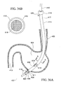
- FIG. 36A illustrates an isometric view of an overtube according to a fourth embodiment, where the overtube is shown together with an endoscope, and the overtube and the endoscope are inserted through an incision in the stomach.
- a cutaway of the distal end of the overtube shows a view of a gas seal between the overtube and the endoscope.
- An opening in the wall of the overtube allows gas flow between the stomach and the lumen of the overtube.
- FIG. 36B illustrates a sectional view taken along line A-A in FIG. 36A .
- FIG. 37 is a schematic of the connection of the overtube to a suction device.
- the suction device removes gas from the lumen of the overtube.
- a valve between the two devices controls the application of suction to the overtube.
- FIG. 38 is a schematic of an alternative embodiment illustrating that if an automatic gas control device is connected to the overtube, it can both inject gas into and remove gas from the overtube lumen.
- Medical system 1 includes a system controller 3 mounted on a cart 2 , an endoscope system 5 which includes an endoscope 4 which is inserted into a body, an air supply system 6 , a monitor 7 which is the display device, a collective panel 8 , and a collective operating panel 9 .
- the system controller 3 entirely controls the medical system 1 .
- a collective display panel 8 Connected to the system controller 3 are a collective display panel 8 , a collective operating panel 1 , and an endoscope system 5 and the like so that through a two-way communication can be carried out via a communication line not shown in the drawings.
- the endoscope system 5 accomplishes a medical operations to a hollow organ or the abdominal cavity from the mouth of the patient, and includes the flexible the endoscope 4 , a camera control unit (hereinafter referred to as CCU) 10 , a light source 11 , an air and water supply device 12 , and an aspirator 13 .
- CCU camera control unit
- the endoscope 4 includes an operating unit 21 operated by an operator, and a long flexible insertion device is extendably attached from the operating unit 21 .
- the operating unit 21 is arranged with an angle knob 23 which bends the insertion device 22 , and various buttons 24 , connected to the system light source 11 by means of a universal cable 25 .
- a treatment tool insertion portion 26 for inserting the treatment tool, and to which a stopper 27 is tightly fitted.
- the endoscope 4 is inserted through the stomach ST through an overtube 30 which guides its insertion to within the body.
- the overtube is not necessarily required.
- a bendable end unit 31 To the distal end of insertion unit 22 is attached a bendable end unit 31 . As shown in FIG. 1B , on the distal end surface of the insertion unit 22 is arranged an observation device 32 , an illumination device 33 , an end opening of an air and water channel 34 , an end opening of an aspiration channel 35 , and an end opening of a the operation channel 36 .
- the observation device 32 includes an observation optical system and photographic image device, which converts an in vivo optical image to an electrical signal, and outputs it to the CCU 10 through the universal cable 25 .
- the CCU 10 converts an electrical signal sent from the observation device 32 to a video signal, and displays the in vivo optical image on a monitor 7 or the collective display panel 8 .
- the illumination device 33 includes an illumination window and light guide, which provides in vivo illumination with illumination light supplied from the light source 11 .
- Air and water are supplied to the air and water supply channel 34 from the air and water supply device 12 through the universal cable 25 .
- the aspiration channel 35 is connected to the aspirator 13 through the universal cable 25 .
- An operation channel 36 is connected to the treatment tool insertion portion 26 on the side of the operating unit 21 passing within insertion unit 22 .
- the structure of the endoscope 4 is not limited to this.
- the work channel 36 may be used for suction work instead of omitting the suction channel 35 .
- the monitor 7 receives a video signal output from the CCU 10 , and the endoscope picture image is displayed.
- the display screen e.g., a liquid crystal display is attached to the collective display panel 8 .
- the collective display panel 9 has a display screen collectively displaying the image output by the endoscope and operation state of components output from the system controller.
- the concentrated operation panel 9 is configured susceptible of input associated with various operation and setup by means of a touch sensor. Each system can be remotely operated using the concentrated operation panel 9 .
- Primary structural components of the air supply system 6 are a gas cylinder 40 which is the supply source of the liquid used for insufflation, an air supply device 41 , and the tubes 42 , 43 , and 44 which extend toward the patient from the air supply device 41 .
- a gas cylinder 40 is filled with a liquefied high-pressure carbon dioxide gas.
- a high-pressure gas tube 45 extending from the gas cylinder 40 is coupled to a high-pressure metal cap 46 of the air supply device 6 .
- Provided to the air supply device 41 in addition to the high-pressure metal cap 46 are an insufflation metal cap 47 , a luminal metal cap 48 , and a pressure measurement metal cap 49 .
- the tube 42 connected to the insufflation metal cap 47 is connected to an pneumoperitoneum needle 50 .
- the tube 43 connected to the luminal metal cap 48 is connected to the air and water supply channel 34 through the universal cable 25 of the endoscope 4 .
- the tube 44 connected to the pressure measurement metal cap 49 is inserted from stopper 27 of the endoscope 4 , and is led to the distal end of the operating channel 36 .
- the tubes 42 - 44 are formed from silicon resin or Teflon®.
- FIG. 2 shows the air supply device 41 in a schematic view.
- a decompressor 63 is provided downstream relative to the supply pressure sensor 61 . The decompressor 63 reduces the high-pressure gas to a specific pressure.
- a first flow path 64 directed toward the insufflation metal cap 47 is formed downstream of the decompressor 63 where a second flow path 65 separating from the first flow path 64 , is extended toward the luminal metal cap 48 .
- a first electropneumatic proportional valve 66 is provided in the first flow path 64 in the order from the upstream.
- the first electropneumatic proportional valve 66 changes the force of the decompression spring operating on the valve based on a control signal from the controller 62 , electrically regulating the pressure of carbon dioxide gas.
- the first electropneumatic proportional valve 66 regulates the air supply pressure of the carbon dioxide gas within a range between 0 to 80 mmHg.
- the first pressure sensor 68 measures the pressure value Pa within the abdominal cavity AC through the first flow path 64 .
- the first flow rate sensor 69 measures the flow rate of carbon dioxide gas flowing through the first flow path 64 , and outputs it to the controller 62 .
- the first relief valve 103 is a solenoid-controlled valve which accomplishes an open/close operation by means of a signal from the controller 62 .
- a second electropneumatic proportional valve 71 is provided in the second flow path 65 in the order from the upstream.
- the second electropneumatic proportional valve 71 regulates the air supply pressure of the carbon dioxide gas within a range between 0 to 500 mmHg by means of the control signal of the controller 62 .
- the second relief valve 73 is a solenoid-controlled valve which accomplishes an open/close operation based on the control signal from the controller 62 .
- the second flow rate sensor 74 measures the flow rate of carbon dioxide gas flowing through the second flow path 65 , and outputs it to the controller 62 .
- a second pressure sensor 75 measures the pressure value Ps in the stomach ST, and its output is input to the controller 62 .
- a setting operation unit 76 and a display 77 are also connected to the controller 62 .
- the setting operation unit 76 and the display 77 receive a particular display or operation related to the air supply device 41 , and are provided, for example, on the front surface panel of the air supply device 41 .
- an electric power switch, an air supply start button, or an air supply suspension button may be used.
- the display 77 may be a residual gas amount display displays the result of output obtained by the supply pressure sensor 61 .
- Described hereunder is a procedure for treating an organ or a tissue (hereunder, called a target site) by means of the endoscope 4 inserted through natural orifice of an organ, e.g., a mouth of a patient.
- an organ or a tissue hereunder, called a target site
- the natural orifice subject to the insertion of the endoscope 4 is not limited to the mouth, and may be a nostril or an anus.
- treatments as a medical operation are applicable to various actions such as suture, observation, incision, and cell sampling.
- the insertion unit 22 of the endoscope 4 is inserted from the mouth of the patient, and the distal end of the insertion unit 22 is introduced into the stomach ST.
- the pneumoperitoneum needle 50 is inserted into the abdominal cavity AC through the abdominal wall of the patient.
- the carbon dioxide gas within the air cylinder 40 is delivered to the air and water supply channel 34 in the endoscope 4 through the tube 43 from the second of flow path 65 , further to the inside of the stomach ST from the distal end opening. Inflow of carbon dioxide gas increases the pressure in the stomach ST.
- the pressure value Ps of the stomach ST obtained through the tube inserted into the operating channel 36 is measured by the second pressure sensor 75 .
- the controller 62 compares the pressure value Ps (actually measured value) of the second pressure sensor 75 with the target pressure set by the operator. If the pressure value Ps does not reach the target pressure, degree of opening of the second electropneumatic proportional valve 71 is adjusted according to the difference between the target pressure and the pressure value Ps, thereby changing the air supply pressure. On the other hand, if the pressure value Ps is greater than the target pressure, the second solenoid-controlled valve 72 is closed, stopping the supply of carbon dioxide gas to the stomach ST, and atmospheric release is accomplished by opening the second relief valve 73 , if necessary. In this manner, the air supply device 41 controls to maintain the air in the stomach ST at a specific pressure.
- a high frequency treatment tool or a clip or the like may also be used for providing a mark to the target position of the body to be incised.
- the operator manipulating the concentrated operation panel 9 or air supply unit 41 selects the air supply to the tube 42 .
- the operator sets the pressure within the abdominal cavity AC.
- the controller 62 shown in FIG. 2 actuates the first electropneumatic proportional valve 66 , thereby opening a first solenoid-controlled valve 67 .
- the degree of opening of the first electropneumatic proportional valve 66 is set by the controller 62 based on the output of the first pressure sensor 68 and the first flow rate sensor.
- Carbon dioxide gas in the compressed gas cylinder 40 is sent from the first flow path 64 to the abdominal cavity through the pneumoperitoneum needle 50 and the tube 42 .
- the inflow of the carbon dioxide gas increases the pressure in the abdominal cavity AC.
- the pressure value Pa of the abdominal cavity AC can be measured by the first pressure sensor 68 .
- the controller 62 closes the first solenoid-controlled valve 67 to measure the pressure in the abdominal cavity AC. Since the supply of carbon dioxide gas from the air cylinder 40 is suspended, the measurement value obtained by the first pressure sensor 68 after the lapse of a predetermined time period becomes the pressure value Pa in the abdominal cavity AC.
- the controller 62 compares the pressure value Pa (actual measured value) of the abdominal cavity AC measured by the first pressure sensor 68 with a target pressure set by the operator. If the pressure value Pa does not reach the target pressure, the degree of opening of the first electropneumatic proportional valve 66 is adjusted based on the difference between the target pressure and the pressure value Pa, thereby changing the air supply pressure. On the other hand, if the pressure value Pa is greater than the target pressure, the first solenoid-controlled valve 67 is closed, and the supply of carbon dioxide gas to the abdominal cavity AC is suspended. Subsequently, opening the first relief valve 103 to release it to the atmospheric pressure decreases the pressure value Pa in the abdominal cavity AC. This is how the air supply device 41 controls to maintain the pressure in the abdominal cavity AC at a specified pressure.
- pressure in the stomach ST may be regulated greater than that in the pressure in the abdominal cavity AC.
- the air in the stomach ST is exhausted by the air supply device 41 and the pressure value Ps in the stomach ST is reduced to the pressure value Pa of the abdominal cavity AC or less.
- the first solenoid-controlled valve 67 is closed, and the pressure value Pa of the first pressure sensor 68 is obtained (step S 101 ).
- the second solenoid-controlled valves 72 are closed, and the pressure value Ps of the second pressure sensor 75 is obtained (step S 102 ).
- the controller 62 compares the values of the pressure values Pa and Ps, and if the pressure value Ps in the stomach ST is greater than the pressure value Pa of the abdominal cavity (YES in step S 103 ), then a second relief valve 73 is opened (in step S 104 ). Since the second relief valve 73 is provided to the second flow path 65 of the air supply device 41 , carbon dioxide gas in the stomach ST is exhausted to the outside of the body through the air and water supply channel 34 . Subsequently, the process returns to the step S 101 , and the steps S 101 to S 104 are repeated until the pressure value Ps in the stomach ST reaches the pressure value Pa of the abdominal cavity AC or lower.
- step S 105 the procedure may proceed to step S 105 when the pressure value Ps in the stomach ST becomes lower by a specific difference than the pressure Pa.
- a treatment tool used for making incision e.g., a high frequency knife
- a treatment tool used for making incision is passed through operation channel 36 of the endoscope 4 , and the stomach wall is incised.
- the incision can be conducted directly by a knife of a high-frequency type.
- an opening PO is formed in the stomach wall.
- the pressure value Ps in the stomach ST is equal to or less than the pressure value Pa within the abdominal cavity AC, outflow of carbon dioxide gas or any other fluid (hereinafter referred to as a fluid) from the stomach ST to the abdominal cavity AC can be prevented, keeping the abdominal cavity AC clean, and preventing infection, from the viewpoint of using pressure control in the stomach ST and the abdominal cavity AC.
- the insertion unit 22 is advanced, and the abdominal cavity AC is accessed by passing the endoscope 4 and the overtube 30 through the opening PO made by incising the stomach wall. At this time, carbon dioxide gas delivered through the first flow path 64 of the air supply device 41 insufflates the abdominal cavity. While performing medical operations within the abdominal cavity AC, the second solenoid-controlled valve 72 is maintained in its closed state, and no air is delivered through the second flow path 65 . Another insulation is conducted in this step because a space for performing the medical operation must be provided within the abdominal cavity AC.
- the endoscope 4 is advanced in the insufflated abdominal cavity AC, and the distal end surface of the endoscope 4 is faced toward the target site W.
- treatment is conducted using the treatment tool 80 passing through the operating channel 36 .
- forceps passing through the operating channel can be used to remove a tissue.
- a high frequency treatment tool passing through the operating channel 36 can burn the target site W.
- smoke produced at the time of burning is discharged to the outside of the body through the aspiration channel 35 or the air supply device 41 so as to ensure the clear field of view of the endoscope 4 .
- the endoscope 4 and the overtube 30 are withdrawn to the stomach ST. Since no carbon dioxide gas is supplied to the stomach ST since cutting the stomach wall until the completion of the medical operation, the pressure value Ps in the stomach ST is equal to or less than the pressure value Pa of the abdominal cavity AC. Furthermore, since the opening PO of the stomach ST is pressed and broadened by the overtube 30 , the opening PO is spontaneously closed by removing the overtube 30 . Accordingly, even if the endoscope 4 and the overtube 30 are withdrawn to the stomach ST, there is no outflow of fluid from the stomach ST to the abdominal cavity AC.
- the operator may confirm that the pressure value Ps in the stomach ST is equal to or less than the pressure value Pa of the abdominal cavity AC prior to withdrawing the endoscope 4 and the overtube 32 to in the stomach ST.
- a separate pipe channel is inserted into the stomach ST from the mouth (natural orifice) of the patient, and the pressure value Ps is confirmed by viewing a pressure gauge connected to the pipe channel. This reliably prevents the outflow of the fluid from the stomach ST to the abdominal cavity AC.
- the pressure value Ps in the stomach ST is equal to or less than the pressure value Pa of the abdominal cavity AC, the pressure in the stomach ST is reduced in accordance with the flow shown in FIG. 3 .
- the opening PO is sutured from the inside of the stomach ST using a suture instruments passing through the operating channel of the endoscope 4 which has been returned to the stomach ST.
- a leak test may be carried out in order to confirm that the opening PO has been completely sutured.
- water is supplied to the sutured portion of the stomach ST from the air and water supply channel 34 of the endoscope 4 . If the suture is incomplete, bubbles are produced in the stomach ST. If no bubbles are produced, the water in the stomach ST will be absorbed through the aspiration channel 35 of the endoscope 4 .
- the tube 42 After suspending the supply of carbon dioxide gas to the abdominal cavity AC, the tube 42 is removed from the pneumoperitoneum needle 50 , and the gas is discharged into the atmosphere from the abdominal cavity AC.
- the controller 62 opens the second relief valve 73 to discharge carbon dioxide gas of the stomach ST, thereby returning the stomach ST to atmospheric pressure.
- the pneumoperitoneum needle 50 is removed from the abdominal wall, and the endoscope 4 and the overtube 30 are removed from the patient's mouth.
- the pressure of the abdominal cavity AC is controlled during the medical operation using the endoscope inserted from the mouth of the patient so that the pressure value Ps in the stomach ST should be equal to or less than the pressure value Pa of the abdominal cavity AC prior to making an incision in the stomach ST.
- the pressure in the stomach ST must be higher than the pressure within the abdominal cavity AC in ordinary cases where an opening of the stomach wall of a target site must be confirmed. In such cases, releasing as desired the pressure in the stomach ST can prevent an outflow of fluid from the stomach S to the abdominal cavity AC when the stomach ST is incised, thereby maintaining the abdominal cavity clean and preventing infection.
- an outflow of fluid from the stomach ST to the abdominal cavity AC can be prevented when the endoscope 4 and the overtube 30 are withdrawn from the abdominal cavity AC to the stomach ST after the completion of a medical operation, since the pressure value Ps in the stomach ST is equal to or less than the pressure Pa of the abdominal cavity AC during the period in which a medical operation is performed in the abdominal cavity AC.
- the abdominal cavity AC can be maintained clean similarly to the inserted state, thereby preventing infection.
- the luminal metal cap 48 of the air supply device 41 is connected to the air and water supply channel 34 of the endoscope 4 through the tube 43 .
- the insufflation metal cap 47 is connected to a lumen of the treatment tool, e.g., a puncture needle 90 through the tube 42 .
- the puncture needle 90 is passed through the operating channel 36 via a stopper 91 attached to the treatment tool insertion portion 26 of the endoscope 4 .
- the stopper 91 has two branches. A pressure-measuring tube 44 is inserted into an opening of one of the branched portions.
- the puncture needle 90 has a needle member 96 that can freely extend and retract in a protective sheath 95 .
- a lumen is formed within the needle member 96 .
- the proximal end of the lumen is connected to a tube 42 .
- An opening 97 is formed in the vicinity of a sharp tip of a needle member 96 on the distal end of the lumen.
- the present embodiment differs from the first embodiment only with respect to a route for supplying carbon dioxide gas at the time of insufflation.
- the puncture needle 90 is inserted through the operating channel 36 of the endoscope 4 , connected to the air supply device 41 , and further inserted into the patient's stomach ST.
- Carbon dioxide gas is supplied next to the air and water supply channel 34 to inflate the stomach ST.
- the pressure value Ps in the stomach ST is measured by a second pressure sensor 75 of the air supply device 41 through the tube 44 inserted into the two-way stopper 91 .
- the puncture needle 90 As shown in FIG. 7 , advancing the needle member 96 of the puncture needle 90 penetrates the stomach wall SW. At this time, the puncture needle 90 is pressed into the stomach wall SW until the distal end opening 97 of the lumen is exposed to the abdominal cavity AC.
- the abdominal cavity AC is insulated by carbon dioxide gas supplied from the first flow path 64 of the air supply device 41 .
- the carbon dioxide gas is provided to the abdominal cavity AC through the lumen within the puncture needle 90 .
- the pressure value Pa of the abdominal cavity AC is measured by the first pressure sensor 68 (see FIG. 2 ).
- the pressure value Ps in the stomach ST is set higher than the pressure value Pa of the abdominal cavity AC when the target site for cutting the stomach ST is confirmed.
- the second relief valve 73 (see FIG. 2 ) of the air supply device 41 is released to the atmospheric pressure to control the pressure in the stomach ST
- the stomach wall SW is incised. If the pressure value Ps in the stomach ST is equal to or less than the pressure value Pa of the abdominal cavity AC, an opening PO is formed by incising the stomach wall SW.
- the puncture needle 90 is withdrawn from the stomach wall SW when inserting the endoscope 4 into the abdominal cavity AC through the opening PO. After incising the stomach wall SW and inserting endoscope 4 and the overtube 30 therethrough, the insertion unit 22 is advanced to access the abdominal cavity AC.
- the controlled pressure in the stomach ST and abdominal cavity AC prevents the outflow of fluid from the stomach ST to the abdominal cavity AC, thereby continuously maintaining the clean state and preventing infection. Furthermore, since there is no need for implanting the pneumoperitoneum needle 50 in the abdominal wall, the medical operations can be conducted without causing an injury to the patient.
- FIG. 8 shows the structure of the air supply device used in the present embodiment.
- An air supply device 101 has a second pressure sensor 104 , the second flow rate sensor 74 , and a second relief valve 105 in this order is connected to the second solenoid-controlled valve 72 on the second flow path 65 branching from the decompressor 63 .
- the air supply device 101 is connected to the tube 43 .
- the first and second relief valves 103 and 105 respectively are solenoid-controlled valves capable of being atmospherically released by the control signal of the controller 62 .
- the tube 42 extending from the insufflation metal cap 47 of the air supply device 101 is connected to the lumen of the puncture needle 90 .
- the tube 43 extending from the luminal metal cap 48 is connected to an overtube 110 .
- a long flexible pipe 112 extends from the proximal end 111 of the overtube 110 .
- an air tight valve (not shown in the drawing) forming air tight construction between the endoscope 4 and the overtube 110 .
- a port 113 Provided protrudingly toward the distal end from the air tight valve is a port 113 to which the tube 44 is connected. A hole which communicates with the overtube 110 is formed in the port 113 .
- insufflating the stomach ST by supplying carbon dioxide gas through the overtube 110 , thereby inflating the stomach ST and further insufflating the abdominal cavity AC with a puncture needle 90 .
- the pressure control is conducted in accordance with the flow shown in FIG. 10 in order to incise the stomach wall while the pressure value Ps in the stomach ST is higher than the pressure value Pa of the abdominal cavity AC.
- the first solenoid-controlled valve 67 is closed, and the pressure value Pa of the first pressure sensor 68 is obtained (in step S 201 ) after a predetermined lapse of time period.
- the second solenoid-controlled valve 72 is closed, and the pressure value Ps of the second pressure sensor 104 is obtained (in step S 202 ) after a predetermined lapse of time period.
- the controller 62 compares the pressure values Pa and Ps, and if the pressure value Ps in the stomach ST is greater than the pressure value Pa of the abdominal cavity AC (Yes in step S 203 ), the second relief valve 105 is opened (in step S 204 ).
- step S 205 the timer of the controller 62 starts and the controller 62 stands-by (in step S 205 ) until a predetermined time is reached.
- step S 206 the second relief valve 105 is closed (in step S 206 ), and the flow returns to step S 201 .
- steps S 201 to S 202 are repeated until the pressure value Ps in the stomach ST drops to the pressure value Pa of the abdominal cavity AC or less.
- the second relief valve 105 Since the second relief valve 105 is in the second flow path 65 , it is difficult to accurately detect the pressure in the stomach ST with the second pressure sensor 104 while the second relief valve is in the open state; therefore, the release of the second relief valve 105 occurs only for the predetermined time. Also, if the pressure value Ps in the stomach ST is equal to or less than the pressure value Pa of the abdominal cavity AC (in step S 203 ), processing of this flow is terminated. Moreover, the process may be terminated when the pressure value Ps in the stomach ST reaches a value which is lower than the pressure value Pa by a specified amount.
- the stomach wall is incised, and the endoscope 4 and overtube 110 are advanced to access the abdominal cavity AC. Subsequent medical operations are the same as those of the second embodiment.
- independent pressure adjustment can be conducted since the pressure sensor 68 and the relief valves 103 are provided in the flow path 64 directed to the abdominal cavity AC, and the pressure sensor 104 and the relief valves 105 are provided in the flow path 65 directed to stomach ST. Also, the second pressure sensor 104 provided in the second flow path 65 eliminates necessity to arrange another pressure-measuring tube, thereby facilitating piping arrangement. Other effects are the same as those in the second embodiment.
- FIG. 11 shows the structure of the air supply device used in the present embodiment.
- An air supply device 121 is connected to an aspirator 122 in the second flow path in lieu of the second relief valve.
- the connection among the air supply device 121 , the endoscope 4 , and overtube 110 is the same as that in the third embodiment.
- FIG. 12 After the insertion unit 22 of the endoscope 4 is inserted through the stomach ST, the stomach wall SW is penetrated by the puncture needle 90 .
- the abdominal cavity AC is insufflated by supplying carbon dioxide gas through the puncture needle 90 .
- carbon dioxide gas is supplied from the overtube 110 to inflate the stomach ST until the pressure in the stomach ST is higher than the pressure within the abdominal cavity AC.
- the overtube 110 is advanced while the endoscope 4 is fixed after confirming the position subject to an incision. As shown in FIG. 13 , the distal end portion of the overtube 110 is abutted to the stomach wall SW, including the position of the incision.
- the first solenoid-controlled valve 67 is closed, and after a predetermined lapse of time, the pressure Pa of the first pressure sensor 68 is obtained (in step S 301 ). Further, the second solenoid-controlled valve 72 is closed, and after the lapse of a predetermined time period, the pressure value Ps of the second pressure sensor 104 is obtained (in step S 302 ). If the pressure value Ps is higher than the pressure value Pa (Yes in step S 303 ), the aspirator 122 is actuated. Since the second solenoid-controlled valve 72 is closed, carbon dioxide gas within the overtube 110 is absorbed.
- the timer starts and the controller 62 stands-by (in step S 304 ) until a predetermined time is reached, and then the aspirator 122 is terminated (in Step S 305 ). Subsequently, the flow returns to step S 301 .
- the processes up to this point are repeated, and the process is terminated when the pressure value Ps becomes equal to or less than the pressure value Pa (No in step 303 ). Moreover, the process may be terminated when the pressure value Ps in the stomach ST reaches a value which is lower than the pressure value Pa by a specified amount.
- the stomach wall SW including the target incision position is drawn to the space 123 formed at the distal end of the overtube 110 .
- the puncture needle 90 is removed from the operating channel 36 , and is replaced by a high-frequency knife.
- an opening is formed by incising the target open position with the distal end 131 of the high-frequency knife 130 .
- the necessary medical operation is executed after advancing the endoscope 4 and the overtube 110 through the opening PO to access the abdominal cavity AC. Insufflation necessary during this period is executed by using the overtube 110 .
- the endoscope 4 is returned to the stomach ST, i.e., the inside of the overtube 110 . Since air is not delivered to the entire stomach ST, the pressure value Ps in the stomach ST is equal to or less than the pressure value Pa of the abdominal cavity AC, and there is no outflow of fluid from the stomach ST to the abdominal cavity AC.
- the time required to adjust the pressure can be shortened in the present embodiment since aspiration is accomplished by the aspirator 122 in lieu of accomplishing atmospheric release of the entire stomach ST for reducing the pressure value Ps. Furthermore, since the absorption conducted by the aspirator 122 absorbs the stomach wall SW including the target incision position into the overtube 110 provides a distance between the outside of the stomach wall SW and the other organs or abdominal wall. Owing to this, the stomach wall SW can be incised without affecting the other organs. Other effects are the same as indicated above.
- the stomach may be inflated, and marking may be provided to the target incision position by means a high-frequency treatment tool or a detainment tool, such as a clip. Furthermore, after providing the marking and absorbing the carbon dioxide gas having been supplied in order to inflate the stomach ST with the aspirator 122 to reduce the pressure in the stomach ST, the distal end of the overtube 110 may be abutted to the stomach wall SW so absorb the space 123 partitioned by the stomach wall SW, including the overtube 110 .
- FIG. 17 shows a system of medical treatment in the present embodiment in a schematic view.
- An insufflation metal cap 47 of an air supply device 141 is connected to the lumen of the puncture needle 90 .
- the metal cap 48 used in the stomach ST is connected to the air and water supply channel 34 of the endoscope 4 .
- the tube 43 used for pressure measurement in the stomach ST is inserted into the port branched by the stopper 91 of the treatment tool insertion portion 26 .
- the air supply device 141 is configured to have an aspirator 122 attached downstream of the second flow rate sensor 74 in the air supply device shown in FIG. 6 instead of the second relief valve 73 .
- the endoscope 4 is provided with a distal end hood 142 mounted at the distal end of the insertion unit 22 .
- the distal end hood 142 has a cylindrical form, and is secured by a ring 144 in a state in which a ring like protrusion 143 within the periphery of the proximal end side presses against the distal end surface of the endoscope.
- Conducted before medical operations are, inserting the endoscope 4 into the stomach ST, inflating the stomach ST by supplying air from the air supply device 141 , and confirming that the target incision position. Conducted similarly to the fourth embodiment after confirming the target incision position are, abutting the distal end hood 142 to the stomach wall SW including the target incision position, advancing the puncture needle 90 in the distal end hood 142 , and penetrating the puncture needle 90 into the stomach SW. Carbon dioxide gas is supplied from the air supply device 141 through the puncture needle 90 to insufflate the abdominal cavity AC. Next, the air supply device 141 closes the second solenoid-controlled valve 72 , and actuates the aspirator 122 . As shown in FIG.
- the fluid in the space 145 defined by the stomach wall SW and the distal end hood 142 is absorbed through the aspiration channel 34 of the endoscope 4 , and the stomach wall SW is pulled into the distal end hood 142 (the pressure of the space 145 enclosed by the distal end hood 142 is lower than the pressure within the abdominal cavity AC). Subsequently, the puncture needle 90 is removed, and a high-frequency knife is inserted through the operating channel 36 .
- an opening is formed to the distal end 131 of the high-frequency knife 130 by incising the target open position. Since the pressure value Pss within the distal end hood 142 is lower than the pressure value Pa within the abdominal cavity AC, there is no outflow of liquid from the stomach ST side to the abdominal cavity AC.
- Necessary medical operation is executed by accessing the endoscope 4 to the abdominal cavity through the opening SO.
- the abdominal cavity AC is insufflated through the channel 34 of the endoscope 4 .
- the endoscope 4 is returned to the stomach ST. Since air is not delivered to the entire stomach ST, the pressure value Ps in the stomach ST is equal to or less than the pressure value Pa of the abdominal cavity AC, and there is no outflow of fluid from the stomach ST to the abdominal cavity AC.
- a step may be conducted in which pressure is controlled inside the stomach ST based on the delivery of air only to the abdominal cavity AC, without inflating the stomach ST.
- a insufflation tube 160 used for the abdominal cavity AC and an air supply tube 161 for delivering air to the stomach ST may be provided along the insertion unit 22 separate from the endoscope 4 .
- the tube 160 having one or two lumens is connected to the insufflation metal cap 47 of the air supply device.
- the tube 160 is introduced to the abdominal cavity AC together with the insertion unit 22 and the endoscope 4 into the abdominal cavity AC through the stomach wall. Conducted before the insufflation and incision of the abdominal cavity AC are inserting the pneumoperitoneum needle 50 or the puncture needle 90 into the abdominal cavity AC and supplying air to the abdominal cavity AC.
- the tube 161 is inserted so that its distal end opening remains in the stomach ST. The same effects are obtained as those indicated above in cases where tubes 160 and 161 are inserted separately from the endoscope 4 .
- air supply tubes 170 and 171 may also be fixed to the outer periphery of the insertion unit 22 of the endoscope 4 .
- the tube 170 used for insufflation of the abdominal cavity AC includes one or two lumens and extends to the distal end of the insertion unit 22 .
- the distal end opening of tube 171 which supplies air to the stomach ST is arranged close to the proximal end relative to the tube 171 .
- the distal end of the tube 171 is positioned so that the tube 171 and the insertion unit 22 of the endoscope 4 can be inserted into the stomach ST; and the tube 171 will remain in the stomach ST when the endoscope 4 is introduced into the abdominal cavity through the stomach wall.
- the same effects as those indicated above can be obtained when the tubes 170 and 171 separated from the endoscope 4 are used.
- an air supply tube 181 used for supplying air to the stomach ST may also be fixed along the outer periphery of the overtube 110 in the structure having lumens i.e., the overtube 110 used for insufflation of the abdominal cavity AC.
- the tube 181 also need not be fixed to the overtube 110 .
- insufflation may be conducted through an attached lumen used for air supply within the overtube 110 .
- the port 113 is arranged further to the distal end side from an airtight valve 182 . Conducted before the insufflation and incision of the abdominal cavity AC are inserting the pneumoperitoneum needle 50 or the puncture needle 90 into the abdominal cavity AC and supplying air to the abdominal cavity AC.
- An intragastric pneumoperitoneum needle 190 may be used as shown in FIG. 24 and FIG. 25 .
- the intragastric pneumoperitoneum needle 190 includes three lumens 191 , 192 and 193 .
- the third lumen 193 for air delivery and evacuation to and from the stomach has an opening 196 on the outer circumference in the middle of the longitudinal direction, e.g., toward the proximal end.
- the tube 197 includes three independent lumens.
- each of the intragastric pneumoperitoneum needle 190 are connected to each independent lumens.
- the insufflation lumen 191 is connected to insufflation metal cap 47 of the air supply device.
- the air evacuation lumen 192 is connected to an aspirator which is not shown.
- the lumen 193 for air delivery and evacuation to and from the stomach is connected to the metal cap 47 used within the air supply device in the stomach ST.
- the intragastric pneumoperitoneum needle 190 separated from the endoscope 4 is inserted into the stomach ST through the operating channel 36 of the endoscope 4 so that the needle 190 penetrates the stomach wall SW and the opening 196 of the lumen 193 remains in the stomach ST.
- Air is supplied from the lumen 19 used for abdominal cavity air supply so as to insufflate the abdominal cavity AC. Air is supplied next into the stomach ST through the lumen 193 for air delivery and evacuation to insufflate the stomach ST.
- the lumen 193 for air delivery and evacuation is released to the atmosphere to adjust the pressure in the stomach ST.
- smoke produced when using a high-frequency treatment tool in the abdominal cavity AC is exhausted from the air evacuation lumen 192 for the stomach of the pneumoperitoneum needle 190 .
- the single pneumoperitoneum needle 190 can be of compatible use, e.g., air supply, air expulsion, and pressure adjustment.
- a pipe path for inflating a hollow organ and a pipe path for insufflation of the abdominal cavity AC may be inserted from different natural orifices.
- the endoscope may be inserted from the patient's mouth while the tube used for insufflation may be inserted from the anus, or air may be supplied to the abdominal cavity AC through the wall of the large intestine.
- the device needed for performing a desired manipulation is not limited to the endoscope comprising the observation device and the work channel described in the above embodiments.
- a device may be used (hereunder, called a treatment device for convenience) comprising a treatment portion for performing a desired treatment provided on the distal side of the insertion portion to be inserted into the body, and an operation portion capable of operating this treatment portion from outside of the body.
- a medical operation is accomplished while making observations with an observation device which can be swallowed, such as a capsule endoscope.
- Transgastric endoscopic exploration and transgastric endoscopic surgery are newly developing techniques for observing, obtaining biopsies and performing surgery in the peritoneal cavity.
- the procedure is typically performed as follows.
- a flexible endoscope 419 with a proximal end 401 and a distal end 402 is passed through the mouth, oropharynx 409 and esophagus 3 into the stomach 404 .
- the stomach is insufflated with gas, typically air, in order to expand the stomach and smooth out any folds in the stomach wall and to create an interior working space in the stomach ST for manipulating the endoscope and locating an ideal site for incising the wall of the stomach.
- the operator With the stomach inflated with gas, the operator then chooses a site on the stomach wall to make a full thickness incision of the stomach wall. Depending upon which abdominal organs the operator desires to inspect, biopsy or perform surgery on, the operator may select to incise the posterior wall of the stomach, the anterior wall of the stomach, or other suitable location on the stomach wall.
- the incision of the stomach wall can be made with a variety of techniques. As illustrated in FIG. 27 , one method is to employ a retractable needle-tipped electrode 405 through the endoscope 419 using radio frequency (RF) cutting or coagulating current to cut through the tissue of the stomach wall, while providing a hemostatic effect on the incised tissue.
- RF radio frequency
- the length of the incision is selected so that it creates an incision or opening in the stomach wall of the approximate diameter, or slightly less than the diameter, of the endoscope.
- the incision 411 is correctly sized, when the endoscope 419 is passed through the wall of the stomach 404 and enters the lumen of the abdominal cavity 412 , the tissue of the stomach wall will create a gas-tight seal around the outer surface of the endoscope.
- a small hole is made in the wall of the stomach.
- a balloon dilator 407 is then passed through this small hole, positioned such that it is approximately centered in the stomach wall 408 , and inflated with sufficient pressure to dilate the small hole in the stomach to a diameter that will allow passage of the distal end of the endoscope 402 . If the opening is dilated to the correct size, it will allow the distal tip 402 of the endoscope to slip through the stomach wall into the lumen 412 of the abdominal cavity, while at the same time creating a gas-tight seal between the outer surface of the endoscope and the stomach wall.
- an overtube 410 provides smooth passage of the endoscope through the oropharynx 409 and through the incision 411 in the stomach wall. Guided passage of the endoscope along this route is very useful if the endoscope is going to be repeatedly withdrawn and reinserted into the patient.
- the overtube can be modified to allow it to control the amount and pressure of gas used to insufflate the stomach—a benefit which is the object of the present invention.
- the length of the gastric wall incision 411 should be made such that the gastric wall forms a gas-tight seal around the outer surface of the overtube 410 through which the endoscope 419 is passed.
- This tight seal between the overtube and the stomach wall serves several purposes. In the first instance it will prevent the leakage of any stomach contents into the lumen 412 of abdominal cavity while the endoscope is being manipulated in the lumen of the abdominal cavity. In the second instance, it will create two gas-tight compartments within the body. After the incision is made in the stomach wall, gas can flow freely between the interior of the stomach 404 and the intraperitoneal space 412 .
- the endoscopist to independently insufflate only the stomach 404 or only the intraperitoneal space 412 .
- the first is the interior of the stomach 404 , along with the small intestines 413 which are joined to the stomach at the region of the pylorus 406 . (See FIG. 32 )
- the second is the intraperitoneal space 412 which is now isolated from communication with the stomach interior 404 since the incision 411 in the stomach wall is tightly plugged with the overtube 410 . In such a condition, the amount of gas pressure and the degree of expansion of these two spaces can be controlled independently.
- the stomach 404 protrudes into the lumen 412 of abdominal cavity reducing the volume of the peritoneal cavity and restricting the endoscopist's ability to manipulate the endoscope and access other organs in the intraperitoneal space.
- the expanded stomach may obscure observation and manipulation of other abdominal organs, making the procedure less effective and more difficult.
- a second disadvantage of having high gas pressure in the stomach is that this gas will pass through the pylorus 406 and insufflate and expand the small intestines 413 as well.
- the small intestines 413 are expanded with gas they also reduce the available working space within the lumen of the abdominal cavity 412 and prevent the endoscopist from effectively observing and operating on other abdominal organs.
- FIG. 28 illustrates the large intraperitoneal space 412 created when the stomach 404 and small intestines 413 are deflated
- FIG. 31 illustrates how an expanded stomach 404 and expanded intestines 413 reduce the size of the intraperitoneal space 412 .
- the object of the present invention is to control the insufflation of the stomach and the small intestines during transgastric endoscopic observation and/or surgery.
- the devices described allow for the decompression of the stomach and small intestines at will, and/or the prevention of gas flowing into the small intestine during the transgastric endoscopic procedure.
- FIGS. 32A and 32B show one embodiment of an overtube 415 that provides stomach insufflation control.
- the overtube 415 is passed through the patient's mouth and oropharynx (not shown) through the esophagus 403 into the patient's stomach 404 .
- An endoscope 419 is passed through this overtube 415 and through an opening 411 in the stomach wall.
- a gas-tight seal between the stomach wall and the outer surface of the endoscope 419 separates the gas compartment of the lumen of the abdominal cavity from the gas compartment of the interior of the stomach and intestines.
- a gas-tight seal 416 between the endoscope 419 and the overtube 415 at the proximal end 417 of the overtube prevents any gas from the stomach 404 from leaking out of the proximal end of the overtube.
- An intraluminal space 418 exists between the interior surface of the overtube 415 and the exterior surface of the endoscope 419 .
- the intraluminal space 418 is contiguous with the interior space of the stomach 404 and the intestines 413 and the lumen of a gas port 420 on the proximal end 417 of the overtube 415 .
- the gas port 420 enables gas to be added or removed from the stomach 404 and intestines 413 during the procedure.
- FIGS. 33A and 33B illustrate another embodiment of the present invention.
- the overtube 415 is inserted through an incision 411 in the stomach wall with the distal end of the overtube 423 residing in the intraperitoneal space 412 .
- the dimension of the stomach wall incision 411 is such that a gas-tight seal is created between the stomach wall and the distal tip 423 of the overtube. This seal separates the intraperitoneal air space 412 from the air space within the interior of the stomach 404 and intestines 413 .
- a tube 424 with lumen is placed along the outer surface of the overtube. The distal end of this lumen opens into the interior of the stomach 404 .
- the proximal end 426 of this lumen connects to a gas port 420 outside of the patient and allows gas to be added to or removed from the interior of the stomach 404 and small intestines 413 .
- An air tight seal 416 between the proximal end 417 of the overtube and the proximal end 419 of the endoscope prevents gas within the intraperitoneal space from escaping up the intraluminal space and out the proximal end 417 of the overtube.
- gas pressure in the stomach ST and the intestines can be controlled by adding or removing gas via the gas port 420 on the tube 424 with lumen.
- the tube 424 with lumen is securely attached to the overtube 415 .
- One means of attachment is the use of adhesive tape 427 , although many other means are available.
- FIG. 34A illustrates a cross-section of the overtube 415 at A-A, illustrating that the gas lumen 428 and the overtube 429 lumen share a common wall 430 .
- the distal end of the gas lumen 428 opens into the stomach.
- the proximal end of the gas lumen communicates with the gas port 420 via connecting tube 434 . Gas injected into or withdrawn from the gas port 420 will therefore add or remove gas respectively from the stomach 404 and intestines 413 .
- the overtube 415 could be extruded with a channel 432 designed to accept the gas lumen 433 , which is then adhered to the overtube 415 with an adhesive.
- Reference numeral 431 indicates an adhesive.
- FIGS. 36A and 36B illustrate another embodiment of the present invention.
- the overtube 415 is inserted through an incision 411 in the stomach wall with the distal end 423 of the overtube residing in the intraperitoneal space 437 .
- the dimension of the stomach wall incision 411 is such that a gas-tight seal is created between the stomach wall and the distal end 423 of the overtube.
- the distal end 423 of the overtube contains a mechanical gas-tight seal between the distal end 423 of the overtube and the exterior surface of the endoscope 419 .
- This gas-tight seal 436 is shown in a cutaway view 439 of the FIG. 36A .
- the gas-tight seal 436 separates the intraperitoneal air space 437 from the intraluminal air space 418 and the air space of the interior of the stomach 404 and intestines 413 .
- An opening 438 in the wall of the overtube 415 allows the air space of the interior of the stomach 404 and intestines 413 to communicate with the intraluminal air space 418 .
- the intraluminal air space 418 also communicates with the lumen of an air port 420 on the proximal end 417 of the overtube 415 .
- a gas-tight seal 416 at the proximal end 417 of the overtube prevents gas in the intraluminal space 418 from escaping out of the proximal end of the overtube.
- the gas pressure in the stomach ST 404 and the small intestines 413 can be controlled, independently of the gas pressure within the lumen of the abdominal cavity 437 .
- Both the gas-tight seal 416 at the proximal end 417 of the overtube and the gas-tight seal 436 at the distal end 423 of the overtube allow easy sliding passage of the endoscope 419 through the overtube 415 .
- passage of gas through the air port 420 can be controlled in a variety of means.
- One means is to leave the air port 420 open at all times to allow gas in the stomach ST and intestines to escape from the patient. Since both the surrounding abdominal organs and the intraperitoneal pressure constantly act to compress the stomach and intestines, venting the stomach and intestines to the atmosphere will allow them to expel much of the free gas within these organs, thereby reducing their protrusion into the intraperitoneal space.
- FIGS. 37A and 37B another means of controlling the gas pressure within the interior of the stomach and intestines is to attach a valve to the gas port 420 which is opened and closed under the control of the endoscopist.
- the gas port 420 would be connected to a suction device. Therefore, opening the valve will apply suction to the intraluminal space in the overtube and will remove gas from the interior of the stomach and intestines.
- the air port could be connected to a gas source such as a pump or compressed gas source.
- a gas source such as a pump or compressed gas source.
- opening the valve would add gas to the interior of the stomach and intestines.
- another means of controlling the gas pressure within the interior of the stomach and intestines is to attach the gas port 420 to an automatic gas control device.
- This automatic controller will accurately maintain the gas pressure within the interior of the stomach and intestines to a preset value by either adding or removing gas as necessary, or will automatically remove all gas in the stomach ST and intestines by applying suction to the gas port, under the control of the endoscopist.
- the gas-tight seal between the endoscope and the overtube can be constructed using several alternative methods commonly known in the art.
- One of these methods is to employ closed-cell foam rubber to make a compressible seal around the outer surface of the endoscope.
- Another commonly used method is to employ a flexible diaphragm made of rubber, polymer or other material, with a central hole through which the endoscope is passed. This central hole expands slightly as the endoscope is placed through it, creating an airtight seal.
- Other methods of sealing between the endoscope and the overtube are known to those working in this field. Any type of gas-tight seal that allows the endoscope to be advanced through, and to be withdrawn from, the overtube is suitable.
- insufflation with CO 2 has the advantage that it is absorbed by the body quicker than air. Therefore if CO 2 is used for insufflating the stomach, and during the procedure CO 2 gas travels into the small intestines thereby expanding them, this CO 2 will be absorbed at a faster rate than if room air had been used for the insufflation. This inherent higher absorption rate of CO 2 gas will speed the deflation of the small intestines, making more room in the intraperitoneal space and improving the ease of performing the procedure.
Abstract
Description
Claims (15)
Priority Applications (1)
| Application Number | Priority Date | Filing Date | Title |
|---|---|---|---|
| US11/653,145 US7988656B2 (en) | 2006-01-13 | 2007-01-12 | Natural orifice medical operation and endoscopic overtube |
Applications Claiming Priority (3)
| Application Number | Priority Date | Filing Date | Title |
|---|---|---|---|
| US75912006P | 2006-01-13 | 2006-01-13 | |
| US11/331,974 US20070163585A1 (en) | 2006-01-13 | 2006-01-13 | Method for accessing abdominal cavity and medical procedure via natural orifice |
| US11/653,145 US7988656B2 (en) | 2006-01-13 | 2007-01-12 | Natural orifice medical operation and endoscopic overtube |
Related Parent Applications (1)
| Application Number | Title | Priority Date | Filing Date |
|---|---|---|---|
| US11/331,974 Continuation-In-Part US20070163585A1 (en) | 2006-01-13 | 2006-01-13 | Method for accessing abdominal cavity and medical procedure via natural orifice |
Publications (2)
| Publication Number | Publication Date |
|---|---|
| US20070255165A1 US20070255165A1 (en) | 2007-11-01 |
| US7988656B2 true US7988656B2 (en) | 2011-08-02 |
Family
ID=38256375
Family Applications (1)
| Application Number | Title | Priority Date | Filing Date |
|---|---|---|---|
| US11/653,145 Expired - Fee Related US7988656B2 (en) | 2006-01-13 | 2007-01-12 | Natural orifice medical operation and endoscopic overtube |
Country Status (6)
| Country | Link |
|---|---|
| US (1) | US7988656B2 (en) |
| JP (1) | JP5097558B2 (en) |
| KR (1) | KR101326417B1 (en) |
| CN (1) | CN101897605B (en) |
| TW (1) | TW200744517A (en) |
| WO (1) | WO2007080971A1 (en) |
Cited By (16)
| Publication number | Priority date | Publication date | Assignee | Title |
|---|---|---|---|---|
| US20100022834A1 (en) * | 2008-07-28 | 2010-01-28 | Olympus Medical Systems Corp. | Endoscope apparatus |
| US20100094284A1 (en) * | 2006-03-08 | 2010-04-15 | Olympus Medical Systems Corp. | Organ incision method |
| US20110218484A1 (en) * | 2010-03-02 | 2011-09-08 | Tyco Healthcare Group Lp | Internally pressurized medical devices |
| US8287556B2 (en) | 2008-06-17 | 2012-10-16 | Apollo Endosurgery, Inc. | Endoscopic suturing system |
| US8540735B2 (en) | 2010-12-16 | 2013-09-24 | Apollo Endosurgery, Inc. | Endoscopic suture cinch system |
| US8679136B2 (en) | 2008-06-17 | 2014-03-25 | Apollo Endosurgery, Inc. | Needle capture device |
| US20140371667A1 (en) * | 2012-06-27 | 2014-12-18 | Olympus Medical Systems Corp. | Gas delivery system and surgery system |
| US20160262600A1 (en) * | 2013-12-26 | 2016-09-15 | Olympus Corporation | Pneumoperitoneum apparatus |
| US9486126B2 (en) | 2008-06-17 | 2016-11-08 | Apollo Endosurgery, Inc. | Endoscopic helix tissue grasping device |
| US9788831B2 (en) | 2013-03-12 | 2017-10-17 | Apollo Endosurgery Us, Inc. | Endoscopic suture cinch system with replaceable cinch |
| US10448946B2 (en) | 2013-03-12 | 2019-10-22 | Apollo Endosurgery Us, Inc. | Endoscopic suture cinch |
| US10661034B2 (en) | 2014-08-15 | 2020-05-26 | Northgate Technologies Inc. | High resolution system and method for controlling high and low insufflation flow rates |
| US20200246056A1 (en) * | 2019-02-05 | 2020-08-06 | Covidien Lp | Gas-enhanced energy-based surgical instrument, system, and method for minimally-invasive surgical procedures |
| US11051800B2 (en) | 2016-08-10 | 2021-07-06 | Apollo Endosurgery Us, Inc. | Endoscopic suturing system having external instrument channel |
| US11141147B2 (en) | 2016-08-10 | 2021-10-12 | Apollo Endosurgery Us, Inc. | Endoscopic suturing system having external instrument channel |
| US11812951B2 (en) | 2008-06-17 | 2023-11-14 | Apollo Endosurgery Us, Inc. | Endoscopic needle assembly |
Families Citing this family (59)
| Publication number | Priority date | Publication date | Assignee | Title |
|---|---|---|---|---|
| US7361170B2 (en) | 2001-11-21 | 2008-04-22 | E-Z-Em, Inc. | Device, system, kit or method for collecting effluent from an individual |
| US7806850B2 (en) | 2005-10-24 | 2010-10-05 | Bracco Diagnostics Inc. | Insufflating system, method, and computer program product for controlling the supply of a distending media to an endoscopic device |
| DE102006054218A1 (en) * | 2006-11-15 | 2008-05-21 | Karl Storz Medizinische Nähsysteme GmbH & Co. KG | Surgical instrument e.g. endoscope, for occluding incision into human body, has occluder that is moved for occluding incision using guidance wire from guidance channel, which is work channel of endoscope |
| EP2094167B1 (en) | 2006-11-30 | 2011-06-29 | Wilson-Cook Medical, Inc. | Visceral anchors for purse-string closure of perforations |
| US8864781B2 (en) | 2007-02-28 | 2014-10-21 | Cook Medical Technologies Llc | Intestinal bypass using magnets |
| US20090023997A1 (en) * | 2007-07-18 | 2009-01-22 | Stokes Michael J | device for insufflating the interior of a gastric cavity of a patient |
| EP2209416A4 (en) | 2007-10-15 | 2014-05-14 | Univ Maryland | Apparatus and method for use in analyzing a patient's bowel |
| JP2009142490A (en) * | 2007-12-14 | 2009-07-02 | Olympus Medical Systems Corp | Water leakage detector for endoscope |
| US9023063B2 (en) | 2008-04-17 | 2015-05-05 | Apollo Endosurgery, Inc. | Implantable access port device having a safety cap |
| CN102099078A (en) | 2008-04-17 | 2011-06-15 | 阿勒根公司 | Implantable access port device and attachment system |
| US20100069710A1 (en) * | 2008-09-02 | 2010-03-18 | Ken Yamatani | treatment method |
| CA2741206C (en) * | 2008-11-03 | 2016-01-12 | G.I. View Ltd | Remote pressure sensing system and method thereof |
| US9295489B2 (en) | 2009-01-21 | 2016-03-29 | Osaka University | Guide tube system for forming pneumoperitoneum and providing route for accessing body cavity |
| EP2445418B1 (en) | 2009-06-26 | 2015-03-18 | Cook Medical Technologies LLC | Linear clamps for anastomosis |
| US8715158B2 (en) | 2009-08-26 | 2014-05-06 | Apollo Endosurgery, Inc. | Implantable bottom exit port |
| US8708979B2 (en) | 2009-08-26 | 2014-04-29 | Apollo Endosurgery, Inc. | Implantable coupling device |
| US8506532B2 (en) | 2009-08-26 | 2013-08-13 | Allergan, Inc. | System including access port and applicator tool |
| EP2496148B1 (en) | 2009-11-03 | 2013-11-20 | Cook Medical Technologies LLC | Planar clamps for anastomosis |
| US8882728B2 (en) | 2010-02-10 | 2014-11-11 | Apollo Endosurgery, Inc. | Implantable injection port |
| WO2011130388A1 (en) | 2010-04-14 | 2011-10-20 | Surti Vihar C | System for creating anastomoses |
| US20110270021A1 (en) | 2010-04-30 | 2011-11-03 | Allergan, Inc. | Electronically enhanced access port for a fluid filled implant |
| US8992415B2 (en) | 2010-04-30 | 2015-03-31 | Apollo Endosurgery, Inc. | Implantable device to protect tubing from puncture |
| US20110270025A1 (en) | 2010-04-30 | 2011-11-03 | Allergan, Inc. | Remotely powered remotely adjustable gastric band system |
| US20120041258A1 (en) | 2010-08-16 | 2012-02-16 | Allergan, Inc. | Implantable access port system |
| US20120065460A1 (en) | 2010-09-14 | 2012-03-15 | Greg Nitka | Implantable access port system |
| JP2012085860A (en) | 2010-10-20 | 2012-05-10 | Fujifilm Corp | Endoscope and endoscope system |
| JP5514075B2 (en) | 2010-11-04 | 2014-06-04 | 富士フイルム株式会社 | Endoscope attachment and endoscope system |
| JP5514077B2 (en) * | 2010-11-05 | 2014-06-04 | 富士フイルム株式会社 | Endoscope hood and endoscope system |
| JP5514083B2 (en) | 2010-11-12 | 2014-06-04 | 富士フイルム株式会社 | Endoscope air supply system, endoscope and endoscope system |
| BR112013012846B1 (en) * | 2010-11-24 | 2020-12-08 | Bracco Diagnostics Inc | insufflation system |
| ES2363550B2 (en) * | 2011-03-31 | 2012-02-24 | Nicolas Anthony Costovici | SYSTEM FOR INSUFLATION OF HEATED GAS IN PATIENTS |
| US8821373B2 (en) | 2011-05-10 | 2014-09-02 | Apollo Endosurgery, Inc. | Directionless (orientation independent) needle injection port |
| US8801597B2 (en) | 2011-08-25 | 2014-08-12 | Apollo Endosurgery, Inc. | Implantable access port with mesh attachment rivets |
| WO2013037370A1 (en) * | 2011-09-12 | 2013-03-21 | Safeair Ag | Methods of manufacturing flexible polymeric medical spiral tubings, tubings made by the methods and uses of the tubings |
| US9199069B2 (en) | 2011-10-20 | 2015-12-01 | Apollo Endosurgery, Inc. | Implantable injection port |
| US8858421B2 (en) | 2011-11-15 | 2014-10-14 | Apollo Endosurgery, Inc. | Interior needle stick guard stems for tubes |
| US9089395B2 (en) | 2011-11-16 | 2015-07-28 | Appolo Endosurgery, Inc. | Pre-loaded septum for use with an access port |
| EP2934347B1 (en) | 2012-12-21 | 2023-02-22 | Ircad | Applicators for modular magnetic anastomosis device |
| US11357932B2 (en) * | 2014-03-25 | 2022-06-14 | Qaelon Medical | Method and system for detecting leaks and/or verifying adequate closure following a medical procedure |
| TWI583343B (en) * | 2014-04-30 | 2017-05-21 | you-ren Wu | Endoscopic expansion of the balloon expansion device |
| WO2016031272A1 (en) * | 2014-08-27 | 2016-03-03 | オリンパス株式会社 | Insufflator |
| US10973998B2 (en) * | 2014-11-05 | 2021-04-13 | Palliare Limited | Method and apparatus for controlling insufflation of a vessel during a surgical or investigative procedure and a system and method for insufflating a vessel |
| CN104800963A (en) * | 2015-02-25 | 2015-07-29 | 韩冰 | Hepatobiliary surgery automatic aspirator |
| WO2017017752A1 (en) * | 2015-07-27 | 2017-02-02 | オリンパス株式会社 | Attachment for endoscopes and endoscope system |
| CN106237417A (en) * | 2016-05-19 | 2016-12-21 | 黄健 | A kind of multi-functional perfusion attracts platform and using method |
| US11771855B2 (en) * | 2017-01-10 | 2023-10-03 | Brian Charles Weiner | Methods of treating medical conditions with oxygen |
| EP3606455A1 (en) * | 2017-03-09 | 2020-02-12 | CSA Medical, Inc. | Catheter sleeve for cryotherapy system |
| CN108324382A (en) * | 2018-01-12 | 2018-07-27 | 苏州贝诺医疗器械有限公司 | The identical strength test equipment of stapler |
| US20190247091A1 (en) * | 2018-02-15 | 2019-08-15 | Biosense Webster (Israel) Ltd. | Transesophageal Catheter With Carbon Dioxide Delivery System For Thermal Protection Of Esophagus |
| CA3087848A1 (en) * | 2018-04-10 | 2019-10-17 | U.S. Patent Innovations Llc | Gas-enhanced electrosurgical generator |
| US11350966B2 (en) * | 2018-06-05 | 2022-06-07 | Conmed Corporation | System and method for controlling gas composition in a surgical cavity during endoscopic surgical procedures |
| CN108685607B (en) * | 2018-06-15 | 2024-02-02 | 首都医科大学附属北京世纪坛医院 | Special constant temperature pneumoperitoneum system of tumour surgery |
| US20210402108A1 (en) * | 2018-08-23 | 2021-12-30 | Fisher & Paykel Healthcare Limited | Supplementary continuous gas supply source for delivery to surgical cavities |
| CN109077757B (en) * | 2018-09-15 | 2020-07-14 | 山西省人民医院 | Pneumoperitoneum control device and method for endoscopic surgery |
| KR102323451B1 (en) * | 2020-09-24 | 2021-11-09 | 재단법인 아산사회복지재단 | Automatic adjustment device of air pressure using endoscope |
| TWI798854B (en) * | 2021-10-04 | 2023-04-11 | 張錦標 | Combined needle endoscope and endoscope system |
| CN113693741B (en) * | 2021-09-10 | 2022-06-14 | 四川大学华西医院 | Controllable system and method for gas perfusion |
| CN114010286B (en) * | 2022-01-05 | 2022-03-15 | 南京利昂医疗设备制造有限公司 | Pneumoperitoneum machine calibration device and method |
| WO2023175596A2 (en) * | 2022-03-16 | 2023-09-21 | Palliare Limited | An insufflator and an endoscope, an insufflating system and a method for carrying out a procedure comprising an insufflator and an endoscope |
Citations (10)
| Publication number | Priority date | Publication date | Assignee | Title |
|---|---|---|---|---|
| US5382231A (en) * | 1993-02-02 | 1995-01-17 | Shlain; Leonard M. | Method for transesophageal retraction of the stomach |
| US5458131A (en) * | 1992-08-25 | 1995-10-17 | Wilk; Peter J. | Method for use in intra-abdominal surgery |
| US6412493B1 (en) * | 2000-07-10 | 2002-07-02 | Chao Song Hsue | Vaginal endoscopic surgical blockage to the innervation of prescaral nerve plexus |
| US20050119617A1 (en) * | 2001-07-09 | 2005-06-02 | Stecker Eric C. | Multifunctional devices |
| US20050222491A1 (en) | 2004-03-31 | 2005-10-06 | Kenji Noda | Method and system for supplying predetermined gas into body cavities of a specimen |
| US20050234391A1 (en) * | 2004-03-31 | 2005-10-20 | Takefumi Uesugi | Method and apparatus for supplying predetermined gas into body cavities of a specimen |
| US7179267B2 (en) * | 2000-03-06 | 2007-02-20 | Tyco Healthcare Group Lp | Apparatus and method for performing a bypass procedure in a digestive system |
| US20070157937A1 (en) * | 2006-01-11 | 2007-07-12 | Olympus Medical Systems Corp. | Medical procedure via natural opening |
| US20070255100A1 (en) | 2006-01-06 | 2007-11-01 | Olympus Medical Systems Corporation | Medical method and medical system conducted percutaneous or using naturally occurring body orifice |
| US20080108871A1 (en) * | 2006-11-06 | 2008-05-08 | Mohr Catherine J | Vacuum stabilized overtube for endoscopic surgery |
-
2007
- 2007-01-12 KR KR1020087019646A patent/KR101326417B1/en active IP Right Grant
- 2007-01-12 JP JP2007553948A patent/JP5097558B2/en active Active
- 2007-01-12 CN CN2010102328277A patent/CN101897605B/en not_active Expired - Fee Related
- 2007-01-12 TW TW096101303A patent/TW200744517A/en unknown
- 2007-01-12 WO PCT/JP2007/050332 patent/WO2007080971A1/en active Application Filing
- 2007-01-12 US US11/653,145 patent/US7988656B2/en not_active Expired - Fee Related
Patent Citations (12)
| Publication number | Priority date | Publication date | Assignee | Title |
|---|---|---|---|---|
| US5458131A (en) * | 1992-08-25 | 1995-10-17 | Wilk; Peter J. | Method for use in intra-abdominal surgery |
| US5382231A (en) * | 1993-02-02 | 1995-01-17 | Shlain; Leonard M. | Method for transesophageal retraction of the stomach |
| US7179267B2 (en) * | 2000-03-06 | 2007-02-20 | Tyco Healthcare Group Lp | Apparatus and method for performing a bypass procedure in a digestive system |
| US6412493B1 (en) * | 2000-07-10 | 2002-07-02 | Chao Song Hsue | Vaginal endoscopic surgical blockage to the innervation of prescaral nerve plexus |
| US20050119617A1 (en) * | 2001-07-09 | 2005-06-02 | Stecker Eric C. | Multifunctional devices |
| US20050222491A1 (en) | 2004-03-31 | 2005-10-06 | Kenji Noda | Method and system for supplying predetermined gas into body cavities of a specimen |
| US20050234391A1 (en) * | 2004-03-31 | 2005-10-20 | Takefumi Uesugi | Method and apparatus for supplying predetermined gas into body cavities of a specimen |
| JP2005287839A (en) | 2004-03-31 | 2005-10-20 | Olympus Corp | Gas feeding device and laparoscopic surgery system |
| JP2005287840A (en) | 2004-03-31 | 2005-10-20 | Olympus Corp | Gas feeding device |
| US20070255100A1 (en) | 2006-01-06 | 2007-11-01 | Olympus Medical Systems Corporation | Medical method and medical system conducted percutaneous or using naturally occurring body orifice |
| US20070157937A1 (en) * | 2006-01-11 | 2007-07-12 | Olympus Medical Systems Corp. | Medical procedure via natural opening |
| US20080108871A1 (en) * | 2006-11-06 | 2008-05-08 | Mohr Catherine J | Vacuum stabilized overtube for endoscopic surgery |
Cited By (28)
| Publication number | Priority date | Publication date | Assignee | Title |
|---|---|---|---|---|
| US8540706B2 (en) * | 2006-03-08 | 2013-09-24 | Olympus Medical Systems Corp. | Organ incision method |
| US20100094284A1 (en) * | 2006-03-08 | 2010-04-15 | Olympus Medical Systems Corp. | Organ incision method |
| US10799232B2 (en) | 2008-06-17 | 2020-10-13 | Apollo Endosurgery Us, Inc. | Method of endoscopic suturing |
| US9486126B2 (en) | 2008-06-17 | 2016-11-08 | Apollo Endosurgery, Inc. | Endoscopic helix tissue grasping device |
| US11534160B2 (en) | 2008-06-17 | 2022-12-27 | Apollo Endosurgery, Inc. | Endoscopic needle assembly |
| US11083364B2 (en) | 2008-06-17 | 2021-08-10 | Apollo Endosurgery Us, Inc. | Endoscopic tissue grasping systems and methods |
| US9867610B2 (en) | 2008-06-17 | 2018-01-16 | Apollo Endosurgery Us, Inc. | Endoscopic suturing system with retained end cap |
| US8679136B2 (en) | 2008-06-17 | 2014-03-25 | Apollo Endosurgery, Inc. | Needle capture device |
| US8287556B2 (en) | 2008-06-17 | 2012-10-16 | Apollo Endosurgery, Inc. | Endoscopic suturing system |
| US11812951B2 (en) | 2008-06-17 | 2023-11-14 | Apollo Endosurgery Us, Inc. | Endoscopic needle assembly |
| US9198562B2 (en) | 2008-06-17 | 2015-12-01 | Apollo Endosurgery, Inc. | Endoscopic needle assembly |
| US20100022834A1 (en) * | 2008-07-28 | 2010-01-28 | Olympus Medical Systems Corp. | Endoscope apparatus |
| US8221313B2 (en) * | 2008-07-28 | 2012-07-17 | Olympus Medical Systems Corp. | Endoscope apparatus |
| US9610412B2 (en) * | 2010-03-02 | 2017-04-04 | Covidien Lp | Internally pressurized medical devices |
| US11298475B2 (en) | 2010-03-02 | 2022-04-12 | Covidien Lp | Internally pressurized medical devices |
| US20110218484A1 (en) * | 2010-03-02 | 2011-09-08 | Tyco Healthcare Group Lp | Internally pressurized medical devices |
| US9089325B2 (en) | 2010-12-16 | 2015-07-28 | Apollo Endosurgery, Inc. | Methods of applying a suture cinch |
| US8540735B2 (en) | 2010-12-16 | 2013-09-24 | Apollo Endosurgery, Inc. | Endoscopic suture cinch system |
| US20140371667A1 (en) * | 2012-06-27 | 2014-12-18 | Olympus Medical Systems Corp. | Gas delivery system and surgery system |
| US9724481B2 (en) * | 2012-06-27 | 2017-08-08 | Olympus Corporation | Gas delivery system and surgery system |
| US10448946B2 (en) | 2013-03-12 | 2019-10-22 | Apollo Endosurgery Us, Inc. | Endoscopic suture cinch |
| US9788831B2 (en) | 2013-03-12 | 2017-10-17 | Apollo Endosurgery Us, Inc. | Endoscopic suture cinch system with replaceable cinch |
| US9861265B2 (en) * | 2013-12-26 | 2018-01-09 | Olympus Corporation | Pneumoperitoneum apparatus |
| US20160262600A1 (en) * | 2013-12-26 | 2016-09-15 | Olympus Corporation | Pneumoperitoneum apparatus |
| US10661034B2 (en) | 2014-08-15 | 2020-05-26 | Northgate Technologies Inc. | High resolution system and method for controlling high and low insufflation flow rates |
| US11141147B2 (en) | 2016-08-10 | 2021-10-12 | Apollo Endosurgery Us, Inc. | Endoscopic suturing system having external instrument channel |
| US11051800B2 (en) | 2016-08-10 | 2021-07-06 | Apollo Endosurgery Us, Inc. | Endoscopic suturing system having external instrument channel |
| US20200246056A1 (en) * | 2019-02-05 | 2020-08-06 | Covidien Lp | Gas-enhanced energy-based surgical instrument, system, and method for minimally-invasive surgical procedures |
Also Published As
| Publication number | Publication date |
|---|---|
| KR20080083711A (en) | 2008-09-18 |
| CN101897605A (en) | 2010-12-01 |
| JP5097558B2 (en) | 2012-12-12 |
| CN101897605B (en) | 2012-11-28 |
| JPWO2007080971A1 (en) | 2009-06-11 |
| KR101326417B1 (en) | 2013-11-11 |
| US20070255165A1 (en) | 2007-11-01 |
| WO2007080971A1 (en) | 2007-07-19 |
| TW200744517A (en) | 2007-12-16 |
Similar Documents
| Publication | Publication Date | Title |
|---|---|---|
| US7988656B2 (en) | Natural orifice medical operation and endoscopic overtube | |
| US20070163585A1 (en) | Method for accessing abdominal cavity and medical procedure via natural orifice | |
| US8252057B2 (en) | Surgical access device | |
| US4779611A (en) | Disposable surgical scope guide | |
| TWI428110B (en) | Over-tube | |
| US8016839B2 (en) | Intra-abdominal medical procedures and device | |
| US20080058851A1 (en) | Method and apparatus for assisting in the introduction of surgical implements into a body | |
| US5400773A (en) | Inflatable endoscopic retractor | |
| US20100261962A1 (en) | Natural orifice transluminal endoscopic surgery overtube and method of introducing multiple endoscopes | |
| JP5124287B2 (en) | Medical indwelling member | |
| US20060241651A1 (en) | Surgical port device and associated method | |
| US20080058603A1 (en) | Method and Apparatus for Assisting in the Introduction of Surgical Implements into a Body | |
| US9381009B2 (en) | Surgical device | |
| US20060212063A1 (en) | Surgical device and associated trans-organ surgical method | |
| KR101037644B1 (en) | Retractor system for laparoscopic surgery | |
| EP1971286A1 (en) | Medical procedure via natural orifice and puncture device | |
| JP2009515605A (en) | Apparatus and method for intragastric and transgastric visualization treatment | |
| US9486240B2 (en) | Inflatable instrument for transanal minimal invasive surgery | |
| US20070163604A1 (en) | Leak test method for medical procedure via natural orifice | |
| US8002695B2 (en) | Medical procedure via natural opening | |
| US8540621B2 (en) | Medical retainer and medical operation using the same |
Legal Events
| Date | Code | Title | Description |
|---|---|---|---|
| AS | Assignment |
Owner name: OLYMPUS AMERICA, INC., PENNSYLVANIA Free format text: ASSIGNMENT OF ASSIGNORS INTEREST;ASSIGNOR:BARLOW, DAVID E.;REEL/FRAME:019631/0271 Effective date: 20070503 Owner name: OLYMPUS MEDICAL SYSTEMS CORP., JAPAN Free format text: ASSIGNMENT OF ASSIGNORS INTEREST;ASSIGNORS:UESUGI, TAKEFUMI;NODA, KENJI;MIKKAICHI, TAKAYASU;AND OTHERS;REEL/FRAME:019641/0732;SIGNING DATES FROM 20070621 TO 20070706 Owner name: OLYMPUS MEDICAL SYSTEMS CORP., JAPAN Free format text: ASSIGNMENT OF ASSIGNORS INTEREST;ASSIGNOR:OLYMPUS AMERICA, INC.;REEL/FRAME:019641/0738 Effective date: 20070503 Owner name: OLYMPUS MEDICAL SYSTEMS CORP., JAPAN Free format text: ASSIGNMENT OF ASSIGNORS INTEREST;ASSIGNORS:UESUGI, TAKEFUMI;NODA, KENJI;MIKKAICHI, TAKAYASU;AND OTHERS;SIGNING DATES FROM 20070621 TO 20070706;REEL/FRAME:019641/0732 |
|
| STCF | Information on status: patent grant |
Free format text: PATENTED CASE |
|
| FEPP | Fee payment procedure |
Free format text: PAYOR NUMBER ASSIGNED (ORIGINAL EVENT CODE: ASPN); ENTITY STATUS OF PATENT OWNER: LARGE ENTITY |
|
| FPAY | Fee payment |
Year of fee payment: 4 |
|
| AS | Assignment |
Owner name: OLYMPUS CORPORATION, JAPAN Free format text: ASSIGNMENT OF ASSIGNORS INTEREST;ASSIGNOR:OLYMPUS MEDICAL SYSTEMS CORP.;REEL/FRAME:036276/0543 Effective date: 20150401 |
|
| AS | Assignment |
Owner name: OLYMPUS CORPORATION, JAPAN Free format text: CHANGE OF ADDRESS;ASSIGNOR:OLYMPUS CORPORATION;REEL/FRAME:039344/0502 Effective date: 20160401 |
|
| MAFP | Maintenance fee payment |
Free format text: PAYMENT OF MAINTENANCE FEE, 8TH YEAR, LARGE ENTITY (ORIGINAL EVENT CODE: M1552); ENTITY STATUS OF PATENT OWNER: LARGE ENTITY Year of fee payment: 8 |
|
| FEPP | Fee payment procedure |
Free format text: MAINTENANCE FEE REMINDER MAILED (ORIGINAL EVENT CODE: REM.); ENTITY STATUS OF PATENT OWNER: LARGE ENTITY |
|
| LAPS | Lapse for failure to pay maintenance fees |
Free format text: PATENT EXPIRED FOR FAILURE TO PAY MAINTENANCE FEES (ORIGINAL EVENT CODE: EXP.); ENTITY STATUS OF PATENT OWNER: LARGE ENTITY |
|
| STCH | Information on status: patent discontinuation |
Free format text: PATENT EXPIRED DUE TO NONPAYMENT OF MAINTENANCE FEES UNDER 37 CFR 1.362 |
|
| FP | Lapsed due to failure to pay maintenance fee |
Effective date: 20230802 |