US7912672B2 - Method and device for evaluating displacement signals - Google Patents
Method and device for evaluating displacement signals Download PDFInfo
- Publication number
- US7912672B2 US7912672B2 US11/795,828 US79582806A US7912672B2 US 7912672 B2 US7912672 B2 US 7912672B2 US 79582806 A US79582806 A US 79582806A US 7912672 B2 US7912672 B2 US 7912672B2
- Authority
- US
- United States
- Prior art keywords
- initial
- acceleration
- sensor
- value
- evaluating
- Prior art date
- Legal status (The legal status is an assumption and is not a legal conclusion. Google has not performed a legal analysis and makes no representation as to the accuracy of the status listed.)
- Expired - Fee Related, expires
Links
Images


Classifications
-
- A—HUMAN NECESSITIES
- A63—SPORTS; GAMES; AMUSEMENTS
- A63B—APPARATUS FOR PHYSICAL TRAINING, GYMNASTICS, SWIMMING, CLIMBING, OR FENCING; BALL GAMES; TRAINING EQUIPMENT
- A63B69/00—Training appliances or apparatus for special sports
- A63B69/0028—Training appliances or apparatus for special sports for running, jogging or speed-walking
-
- G—PHYSICS
- G01—MEASURING; TESTING
- G01C—MEASURING DISTANCES, LEVELS OR BEARINGS; SURVEYING; NAVIGATION; GYROSCOPIC INSTRUMENTS; PHOTOGRAMMETRY OR VIDEOGRAMMETRY
- G01C21/00—Navigation; Navigational instruments not provided for in groups G01C1/00 - G01C19/00
- G01C21/10—Navigation; Navigational instruments not provided for in groups G01C1/00 - G01C19/00 by using measurements of speed or acceleration
- G01C21/12—Navigation; Navigational instruments not provided for in groups G01C1/00 - G01C19/00 by using measurements of speed or acceleration executed aboard the object being navigated; Dead reckoning
- G01C21/16—Navigation; Navigational instruments not provided for in groups G01C1/00 - G01C19/00 by using measurements of speed or acceleration executed aboard the object being navigated; Dead reckoning by integrating acceleration or speed, i.e. inertial navigation
- G01C21/183—Compensation of inertial measurements, e.g. for temperature effects
- G01C21/185—Compensation of inertial measurements, e.g. for temperature effects for gravity
-
- G—PHYSICS
- G01—MEASURING; TESTING
- G01C—MEASURING DISTANCES, LEVELS OR BEARINGS; SURVEYING; NAVIGATION; GYROSCOPIC INSTRUMENTS; PHOTOGRAMMETRY OR VIDEOGRAMMETRY
- G01C21/00—Navigation; Navigational instruments not provided for in groups G01C1/00 - G01C19/00
- G01C21/10—Navigation; Navigational instruments not provided for in groups G01C1/00 - G01C19/00 by using measurements of speed or acceleration
- G01C21/12—Navigation; Navigational instruments not provided for in groups G01C1/00 - G01C19/00 by using measurements of speed or acceleration executed aboard the object being navigated; Dead reckoning
- G01C21/16—Navigation; Navigational instruments not provided for in groups G01C1/00 - G01C19/00 by using measurements of speed or acceleration executed aboard the object being navigated; Dead reckoning by integrating acceleration or speed, i.e. inertial navigation
- G01C21/183—Compensation of inertial measurements, e.g. for temperature effects
- G01C21/188—Compensation of inertial measurements, e.g. for temperature effects for accumulated errors, e.g. by coupling inertial systems with absolute positioning systems
-
- G—PHYSICS
- G01—MEASURING; TESTING
- G01C—MEASURING DISTANCES, LEVELS OR BEARINGS; SURVEYING; NAVIGATION; GYROSCOPIC INSTRUMENTS; PHOTOGRAMMETRY OR VIDEOGRAMMETRY
- G01C22/00—Measuring distance traversed on the ground by vehicles, persons, animals or other moving solid bodies, e.g. using odometers, using pedometers
- G01C22/006—Pedometers
-
- A—HUMAN NECESSITIES
- A63—SPORTS; GAMES; AMUSEMENTS
- A63B—APPARATUS FOR PHYSICAL TRAINING, GYMNASTICS, SWIMMING, CLIMBING, OR FENCING; BALL GAMES; TRAINING EQUIPMENT
- A63B2208/00—Characteristics or parameters related to the user or player
- A63B2208/14—Characteristics or parameters related to the user or player specially adapted for animals
-
- A—HUMAN NECESSITIES
- A63—SPORTS; GAMES; AMUSEMENTS
- A63B—APPARATUS FOR PHYSICAL TRAINING, GYMNASTICS, SWIMMING, CLIMBING, OR FENCING; BALL GAMES; TRAINING EQUIPMENT
- A63B2220/00—Measuring of physical parameters relating to sporting activity
- A63B2220/10—Positions
- A63B2220/13—Relative positions
-
- A—HUMAN NECESSITIES
- A63—SPORTS; GAMES; AMUSEMENTS
- A63B—APPARATUS FOR PHYSICAL TRAINING, GYMNASTICS, SWIMMING, CLIMBING, OR FENCING; BALL GAMES; TRAINING EQUIPMENT
- A63B2220/00—Measuring of physical parameters relating to sporting activity
- A63B2220/10—Positions
- A63B2220/16—Angular positions
-
- A—HUMAN NECESSITIES
- A63—SPORTS; GAMES; AMUSEMENTS
- A63B—APPARATUS FOR PHYSICAL TRAINING, GYMNASTICS, SWIMMING, CLIMBING, OR FENCING; BALL GAMES; TRAINING EQUIPMENT
- A63B2220/00—Measuring of physical parameters relating to sporting activity
- A63B2220/40—Acceleration
-
- A—HUMAN NECESSITIES
- A63—SPORTS; GAMES; AMUSEMENTS
- A63B—APPARATUS FOR PHYSICAL TRAINING, GYMNASTICS, SWIMMING, CLIMBING, OR FENCING; BALL GAMES; TRAINING EQUIPMENT
- A63B2225/00—Miscellaneous features of sport apparatus, devices or equipment
- A63B2225/50—Wireless data transmission, e.g. by radio transmitters or telemetry
Definitions
- the invention relates to a process for evaluating motion signals in three-dimensional space and to a device for implementing the process.
- the problems of the conventional processes described below are solved by a process for evaluating motion signals in three-dimensional space by using at least three acceleration sensors.
- the process includes the steps of obtaining a first initial measurement value in a first initial direction in space, the first initial measurement value being a first determined value, the first initial direction being a first desired direction in space; obtaining a second initial measurement value in a second initial direction in space, the second initial direction being different from the first initial direction; calculating a second desired direction in space and a second determined value from the first initial measurement value and the second initial measurement value, the second desired direction being different from each of the first initial direction and the second initial direction; calculating a third desired direction in space and a third determined value from the first initial measurement value and the second determined value, the third desired direction being different from each of the first desired direction and the second desired direction; and converting the first determined value, the second determined value and the third determined value into a first acceleration value in the first desired direction, a second acceleration value in the second desired direction and a third acceleration value in the third desired direction
- the problems of the conventional devices described below are solved by a device for evaluating motion signals in three-dimensional space.
- the device includes a carrier element, and at least one of an acceleration sensor and a rotational angle/speed sensor.
- the at least one of an acceleration sensor and a rotational angle/speed sensor is attached to the carrier element.
- the invention relates to a device for measuring motion.
- the device detects motion in space by means of several motion sensors.
- the measurement values for at least one direction of motion are processed together with the measurement values for at least one other direction of motion.
- An angular velocity measurement is combined with a linear acceleration measurement.
- Three linear acceleration measurements are combined to convert the accelerations into three corrected directions in space.
- a transformation of this type is useful when it is difficult to attach the sensors so that they are aligned with the directions in space to be measured, which is true especially in the case of measurements on the human body.
- the acceleration sensors can be attached anywhere; the desired directions are determined on the basis of two initial positions.
- the gait cycle during a stride is a complex process.
- the feet are highly complicated structures, each consisting of 26 bones and 31 joints, and they not only carry the human body but also provide elastic suspension for it when shocks occur during walking. They also hold us in a state of balance and sense irregularities in the ground.
- pronation is the inward rotation of the ankle during the gait cycle. Overpronation, that is, too much pronation, is often associated with complaints by runners. Many running shoes are therefore offered with medial supports, which are intended to prevent excessive pronation. Conversely, the use of a pronation support is inappropriate in the presence of underpronation (supination) and is considered a cause of complaints in its own right.
- Various aids and devices are therefore used to measure pronation in athletes.
- Video analysis is often used as a basis for offering advice about running shoes.
- the customer is recorded by a video system as he is running on a treadmill.
- the video is then played back at very slow speed.
- the more-or-less normal pronation movement of the foot as it makes contact can be seen. Because this movement is easy to recognize and because excessive pronation can lead to complaints, the shoe which is recommended is the one with which the customer shows the least pronation.
- Measurement on the treadmill suffers from several disadvantages: First, the required equipment is expensive and occupies a great deal of space. Second, running on a treadmill is not easy and changes the runner's normal running style. In any case, inexperienced customers require full attention. Third, the method itself is highly controversial on scientific grounds because of its inaccuracy. Fourth, the normal pronation movement, which is important for good health, is often overcompensated. Nevertheless, this method is widely used in stores specializing in running shoes.
- the company Currex offers a software program called “MotionQuest” to help with the selection of shoes. After various biomechanical data have been entered, the program searches a database for a suitable shoe.
- the MotionQube Station from Currex makes it easier to enter the data by the use of a scanner. This technology with a scanner is also offered by Rothballer.
- Scanners are also sold with a different type of software, which takes into account only the shape of the sole.
- This program is sold under the name “FootPrint” by Schmitzl Systems and is also used at Runners Point. Many specialty shops arrange “campaign days”, in which measurement systems from certain shoe manufacturers (for example, the Footscan System from Adidas or scanners from Asics) are used.
- the system described here makes it possible to conduct a dynamic measurement while the runner is actually running.
- the system offers the advantage of automatically measuring many strides with high temporal resolution and of averaging them, so that the results can be delivered directly as a shoe recommendation. Above all, however, it can also be used without a treadmill.
- the invention is described on the basis of a device for measuring runners' motions, but it is also suitable for a many other types of motion measurement. Nor is it limited to applications to human beings. For example, 4 sensor units can be attached to the ankles of animals such as horses to document and to analyze their gait.
- acceleration values are usually broken down into their components representing three orthogonal directions in space.
- the three directions are usually identified with the anatomical-physiological directions forward/backward, left/right, and up/down. Up/down is usually defined as the direction in which the force of Earth's gravity acts.
- Integrated circuits (IC's) with acceleration sensors are either already designed and built to measure accelerations in three spatial directions orthogonal to each other, or, if they are designed and built to measure only one or two spatial directions, they can be easily connected mechanically to each other in such a way that accelerations in all three orthogonal directions in space can be measured with three or two of these IC's.
- a sensor unit which can measure accelerations in all three orthogonal spatial directions is called a “3D acceleration sensor” or a “3D sensor”, regardless of whether it is an IC or a mechanically assembled unit consisting of several IC's.
- Rotational angle sensors detect the rotational speed around a single axis of rotation, which is usually perpendicular to the plane of the flat housing of the IC.
- the 3D acceleration sensors be attached at properly selected points, that is, to places on the body where, for example, bony structures are close to the surface of the skin, that is, to places which are covered by only thin layers of muscle or fat or by no such layers at all.
- These locations themselves, however, are not usually oriented in the desired directions.
- the surface of the shin bone slants in a forward-medial direction, and the instep slants forward and down.
- Many good locations, furthermore, are round surfaces, such as the ankles, and therefore do not clearly define a direction for the attachment of a 3D acceleration sensor.
- the attachment of the individual 3D acceleration sensors is highly dependent on the individual anatomical situation, on the circumstances at the time in question, and on chance.
- the orientation of a motion-corrected photoplethysmographlic sensor depends on the individual attachment to the ear and is almost impossible to predict.
- the acceleration sensors can be attached anywhere. Three linear acceleration measurements are combined to convert accelerations measured in more-or-less random directions into three corrected directions in space. The conversion is performed automatically.
- the desired directions are determined on the basis of two initial positions by means of a process described here.
- a transformation of this type is useful when it is difficult to attach the sensors so that they are aligned with the spatial directions to be measured, which is especially true in the case of measurements on the human body.
- FIG. 1 a is a schematic view of a foot of a person
- FIG. 1 b is another schematic view of the foot
- FIG. 2 is a schematic view, showing an embodiment of the device of the present invention and how the device is attached to the foot;
- FIG. 3 shows the relationship among a first initial direction, a second initial direction and a second desired direction
- FIG. 4 shows the relationship among a first desired direction, the second desired direction and a third desired direction
- FIG. 5 is a schematic view, showing the original directions A 1 , A 2 and A 3 of a 3D acceleration sensor which is in a first initial position;
- FIG. 6 is a schematic view, showing the 3D acceleration sensor of FIG. 5 in a second initial position
- FIG. 7 is a table, showing the effect of a coordinate transformation of an embodiment of the process of the present invention.
- FIG. 8 schematically shows the embodiment of the process of the present invention
- FIG. 9 schematically shows a recording unit and an output unit of another embodiment of the device of the present invention.
- FIG. 10 shows another embodiment of the device of the present invention.
- FIG. 11 shows converted motion signals representing foot strikes
- FIG. 12 schematically shows the overall process for generating the motion signals of FIG. 11 ;
- FIGS. 13 a to 13 d show how different shoes are chosen in accordance with different running styles
- FIG. 14 a shows the angular velocity as measured by a rotational speed sensor
- FIG. 14 b shows the time change in the vertical acceleration of the leg
- FIG. 15 shows a comparison between the angular velocity of a neutral shoe and the angular velocity of a shoe with a pronation support
- FIG. 16 shows the aging phenomena of running shoes
- FIGS. 17 a to 17 c are graphs showing the measurement of the vertical acceleration at a leg of a person as measured by an acceleration sensor attached to the leg;
- FIG. 18 a shows the measurement of the angular velocity of the tibia rotation of a person without a special shoe insert
- FIG. 18 b shows the measurement of the angular velocity of the tibia rotation of the person with a special shoe insert
- FIG. 19 is a person's running stride chart as measured by an acceleration sensor and a rotational angle sensor which are attached to the heel cap of the shoe of the person.
- the device described here measures the motions of the test subject, such as those of a customer in a running shoe store, to obtain information on the extent of his pronation.
- the measurement values are automatically evaluated in a data processing system, and a type of shoe recommended for the customer is displayed.
- three measurement sites ( 1 , 2 , 3 in FIG. 1 b ) have proven reliable, which can be used together or each on its own.
- pronation which represents a rotation around the slanted axis of the ankle
- the ankle also undergoes a lateral motion ( 1 in FIG. 1 b ), a rotation of the heel bone, a rotation of the heel cap of the shoe ( 2 in FIG. 1 b ), and a rotation of the shin bone ( 3 in FIG. 1 b ).
- FIG. 2 shows a 3D acceleration sensor attached to the ankle to measure its lateral motion during pronation.
- An elastic fleece strap 3 is put around the leg with the fleece side facing the leg.
- a Velcro strip 4 is glued to the concave inside surface of a plastic shell 5 .
- a 3D acceleration sensor which, in the version shown in FIG. 2 , consists of two 2D acceleration sensors 7 , 8 , which are attached to the surfaces of a plastic cube 6 in such a way that they are at a right angle to each other, is attached to the convex outside surface of the plastic shell 5 .
- the sensors 7 , 8 are connected by a cable 9 to an electronic recorder, which is installed in a cuff 10 .
- the permanently connected unit consisting of the sensors 7 , 8 , the plastic cube 6 , and the plastic shell 5 with the Velcro strap 4 , is simply placed on the ankle covered by the fleece strap 3 .
- the process of the invention makes it possible to attach 3D acceleration sensors to selected locations with any desired orientation.
- the advantages of the smallness and light weight of microchip sensors remain almost completely preserved and are not compromised by housings, the design of which would have to take into account the alignment of the sensors.
- the coordinates are subjected to a mathematical transformation, which can be accomplished immediately by microprocessors, which means that a transformation is carried out for each original measurement value consisting of three directional components.
- the coordinate transformation is accomplished on the basis of initial values, which are determined from the values of two initial measurements. These two initial measurements are made with the 3D acceleration sensor in situ, that is, in the position which it actually occupies in each individual case. The values of the two initial measurements remain valid as long as the 3D acceleration sensor remains in its original position relative to the measured object. The two initial measurements must be made again if the 3D acceleration sensor has changed its orientation relative to the measured object, which can happen, for example, when it is removed and then reattached.
- the information derived from a single initial measurement is, indeed, sufficient to calculate the acceleration component of a single direction in space, such as the vertical direction, as described in U.S. Pat. No. 6,658,292.
- the information derived from a single initial measurement is not sufficient to calculate the components of one or both of the other desired directions—at least not without an additional assumption, such as that one of the other desired directions is in a fixed spatial relationship to one of the original directions.
- An additional assumption of this type is made, for example, in the method described in Equations 34-49 of U.S. Pat. No. 6,305,221 for transforming a reference coordinate system into a coordinate system aligned with the force of gravity.
- Equation 35 it is explicitly assumed between Equation 35 and Equation 36 that zg, xg, and x lie in a plane and that therefore the desired direction xg is in a fixed relationship to the original direction x.
- Equation 35 it is explicitly assumed between Equation 35 and Equation 36 that zg, xg, and x lie in a plane and that therefore the desired direction xg is in a fixed relationship to the original direction x.
- an additional assumption of this type is not possible or desirable, nor is it necessary for the process of the present invention. Without such an additional assumption of a fixed relationship of a desired direction in space to an original direction in space, it is possible to calculate the acceleration component of a second desired direction in space only after making a second initial measurement.
- Two initial measurements are also sufficient to calculate the acceleration components for all three desired directions in space, insofar as the three desired directions are in a fixed relationship to each other (or to the directions of the two initial measurements), which is true when, for example, all three desired directions are orthogonal to each other.
- the coordinate transformation of acceleration values measured in three directions of space into three other desired directions in space corresponds to the mathematical coordinate transformation in vector space.
- R is the vector of the transformed acceleration values in the three desired directions;
- A is the vector of the acceleration values in the three original directions, * is the matrix multiplier, and
- B ⁇ 1 is the inverse of matrix B, where B is formed from the base values of the desired directions (R 1 , R 2 , R 3 in FIGS. 3 and 4 ) in the coordinate system of the original directions (A 1 , A 2 , A 3 in FIGS. 5 and 6 ).
- the coordinate transformation is thus completely described when a method is given which specifies how matrix B is to be determined.
- B ⁇ 1 BT, that is, the inverse matrix is equal to the transposed matrix.
- the device described by way of example uses 2D acceleration sensors from Analog Devices, ADXL210E, which can be read out in both digital and analog fashion. Both possible readouts lead to comparable results within the scope of the selected application, namely, the determination of acceleration components in the lateral, frontal, and vertical directions at the ankles of joggers. In addition to dynamic accelerations, these sensors also measure static accelerations, especially the force of gravity. Without loss of general validity, it is assumed for this example that the static and dynamic accelerations are read out as analog values.
- the analog voltage signal was digitized (4 times per measurement value and averaged).
- the acceleration sensors were calibrated individually for each direction according to the manufacturer's instructions. The signal was measured at +1 g and ⁇ 1 g, and from that the stroke (half the difference) and the zero point (the mean value) were determined.
- Two small circuit boards, each about 1 cm 2 in size and each carrying a 2D acceleration sensor 7 , 8 are glued at an angle of 90° to each other to a support cube 6 , so that a 3D acceleration sensor is obtained, from which values for three orthogonal directions can be read out and which is normalized to 1 g.
- the support cube 6 is attached to a rounded support disk 5 , to the concave inside surface of which a Velcro strip 4 has been glued (about 6 cm 2 ).
- a strip of elastic fleece 3 is placed around the leg of the runner, covering the medial ankle.
- the 3D acceleration sensor is simply attached to the medial ankle by means of the Velcro fastener without concern about the orientation of the support cube and thus without concern about the directions of the sensors, characterized in FIG. 5 by the directions A 1 , A 2 , and A 3 .
- the arbitrary orientation remains stable throughout the course of the motion measurement.
- the two initial directions are measured. Because the selected acceleration sensors can also measure static acceleration, the direction of the prevailing force of gravity is measured at rest by the device described by way of example in each of two initial positions. As the first position, a standing position was selected. The direction of the acceleration due to Earth's gravity during the first initial measurement is designated I 1 in FIG. 5 .
- the second initial direction must be different from the first. It is an essential aspect of the invention, however, that the second initial direction does not have to form a right angle to the first initial direction, even if the desired directions are supposed to be orthogonal to each other. For in practice, initial positions with initial directions which are exactly at a right angle to each other, which also specify the anatomic-physiologically desired directions, and which can also be stably maintained are very difficult to achieve.
- the second initial direction namely, the direction of the force of gravity in the second initial position, is designated I 2 .
- the two initial positions are selected in such a way that the plane (E in FIG. 3 ) defined by the first initial direction and the second initial direction contains a direction desired for the acceleration components (R 3 in FIG. 4 ).
- the plane defined together with the first position is thus the sagittal plane.
- the orthogonality of the desired directions is ensured by a calculation process.
- the measured static accelerations (the median of 5 measurements) of the 3D acceleration sensor in the three directions A 1 , A 2 , and A 3 in the second initial position are stored as an auxiliary vector H which points in a second initial direction I 2 ( FIG. 3 ).
- the cross product X of two three-dimensional vectors results in a vector which is orthogonal to the two starting vectors.
- the length depends on the angle of the starting vectors to each other. Because this is undetermined, the length must be normalized (e.g., by means of the scalar product, or it can be normalized to the force of gravity—see below).
- the vector Y in the third desired direction i.e., R 3 in FIG. 4 (in the forward/backward direction) is determined again by means of a cross product.
- the second initial direction (I 2 in FIGS. 3 and 6 ) does not itself correspond to one of the desired directions but rather merely enters into the calculation which determines the two other desired directions (R 2 , see FIG. 3 , and indirectly R 3 , see FIG. 4 ).
- the effect of the coordinate transformation is shown by way of example in FIG. 7 .
- What is shown is the acceleration, obtained by two-fold differentiation, from 3D space coordinates.
- the acceleration was recorded by 5 infrared video cameras (video control).
- the acceleration values during a stride as can be derived from the pressure measurements with a pressure transducer sole (pressure sole), were relatively low, ranging from ⁇ 0.4 g to +0.4 g.
- the accelerations in the forward/backward direction and in the vertical direction were as much as 4 g and thus approximately 10 times greater (not shown).
- even very small deviations in the attachment of the sensors 7 , 8 result in strong error signals.
- FIG. 7 What is shown is the acceleration, obtained by two-fold differentiation, from 3D space coordinates.
- the acceleration was recorded by 5 infrared video cameras (video control).
- the acceleration values during a stride as can be derived from the pressure measurements with a pressure transducer sole (pressure sole) were relatively low, ranging from ⁇ 0.4 g to +
- the measured signal at the ankle in direction A 3 is shown, as well as the signal in direction R 2 calculated by the method described here.
- the signal R 2 calculated by coordinate transformation in the lateral direction is much more similar to the signal of the video control, because most of the falsifying effects of the vertical direction and of the forward/backward direction have been mathematically eliminated.
- the use of acceleration sensors which measure the static acceleration of the force of gravity makes it possible to determine the initial directions in static initial positions. Otherwise, it would be necessary to measure initial motions (and possibly to average them over a large number of measurement values).
- the vertical direction can, for example, be determined by means of a short, two-legged jump in or out of a standing position; a plane containing the forward/backward direction, for example, can be determined by swinging the leg while standing.
- two motions in the horizontal plane for example, can be measured by drawing the foot or shoe along the floor, and the vertical direction can be determined from the cross product of the two horizontal directions.
- the coordinate systems obtained after the transformation differ from each other when the measurements are made on hills, because, in the first case, the vertical is defined according to the force of gravity, whereas, in the second case, it is defined as normal to the horizontal plane.
- the first initial direction can be determined from the direction of the force of gravity in a standing position; the second initial direction can be determined during a flat, straight run (i.e., the subject is running straight ahead on a level ground).
- a flat, straight run vertical and sideways motions are cyclical and on average do not result in a change of place, whereas the forward motion does result in a change of place.
- the direction of acceleration signals integrated twice over the course of several strides is, for example, defined as the second initial direction.
- the measured direction will correspond not just to the forward motion but will also contain a component of the force of gravity, that is, it will assume an angle to the direction of the force of gravity of less than 90°.
- the plane defined by the direction of the force of gravity (first initial direction) and the direction of motion (second initial direction) contains in any case the forward direction, so that, according to the process described here including two cross product calculations, first the sideways direction and then the forward direction can always be determined orthogonally with respect to each other.
- the integrated acceleration signal To determine the velocity at a certain point in time, the integrated acceleration signal must be set at certain times to certain velocities. This can be done by, for example, zeroing it out at certain times. A simple zeroing-out at the beginning of a measurement leads very quickly to a cumulative systematic error (drift) during the integration. This is especially critical in the case of double integration of accelerations to find the distances traveled, because even small errors in the setting of the velocity in the first drift correction lead to large errors in the distance after the second integration, because the error in the velocity is added in again during each step of the second integration.
- drift cumulative systematic error
- the velocity is zero at the time of the extremum of the acceleration near the foot strike point ( FIG. 7 ).
- the extremum is a minimum, and the velocity in the lateral direction during pronation points in the negative direction.
- the time at which the velocity is zeroed out is determined on the basis of the corrected signal R 2 , not on the basis of the measurement signal A 3 .
- FIG. 8 shows the process in schematic fashion.
- the acceleration values of the sensors (A 1 , A 2 , and A 3 ) are converted by coordinate transformation (3D) to the corrected acceleration values (R 1 , R 2 , and R 3 ).
- the acceleration signal in the vertical direction (R 1 ) is sent to a stride detector (SD), which calculates the foot strike, the heel push-off, and the foot push-off, as described further below.
- SD stride detector
- the signal passes first through a high-pass filter (HP) and a low-pass filter (TP).
- the acceleration signals in the vertical and forward/backward direction (R 1 and R 3 ) can, if needed, be sent to a velocity detector (GD), which determines the running velocity or parameters which correlate with the running velocity, such as the duration of the stride or the duration of the standing phase.
- the acceleration signal in the lateral direction (R 2 ) is filtered to zero by a zero filter (NF) before the first integration (I) in order to prevent the integration from drifting.
- NF zero filter
- the velocity is set to zero when the extreme value detector (ED) determines the extremum conforming to the stride.
- the lateral distance ( 1 in FIG. 1 ) of the ankle is determined.
- the parameter detector (P) determines parameters relevant to pronation from the time curve of the lateral travel of the ankle and the stride durations taken from the stride detector (SD).
- the parameters can be, for example, the maximum deflection during the standing phase (maximum lateral distance) and the return from pronation during the push-off phase (difference between the maximum just mentioned and the value of the deflection during push-off).
- the parameters are corrected according to the running speed or a parameter correlated with that speed, which the velocity detector (GD) determines.
- the running type (T) is determined, such as a “pronator” or a “supinator”.
- SE shoe recommendation
- Filter functions can be used to smooth the signals, as the man of the art knows.
- FIG. 9 shows by way of example a schematic diagram of the type of hardware which can be used, which is designed here in the form of two separate units, namely, a recording unit (a) and an output unit (b).
- the recording unit a the sensors (S 1 , S 2 , . . . Sn) are connected externally (by signal lines 9 ) to the electronic measuring circuit, which is accommodated in a cuff 10 .
- the signals are first sent through separate op-amps (O 1 , O 2 , . . . On), and then they proceed to the inputs of the microprocessor (MP), which performs an analog/digital conversion on the input side.
- a flash memory (F) for intermediate storage of the data is connected to the microprocessor. Because the connection between the two units is wireless in this exemplary device, the microprocessor also has a connection to a radio module (RF) with an antenna (A).
- RF radio module
- the output unit (b) receives the data from the recording unit (a) via the antenna (A) and a radio module (RF) and feeds them to a microprocessor (MP). This is connected to a flash memory (F) and to a RAM (R). A keyboard (T) and a display unit (D) are connected so that the device can be operated and the results displayed. A sound generator (SG) is also provided, the tones of which are sent via an amplifier (V) to the loudspeaker (L). Via the loudspeaker, the device itself can guide the course of the measurements, because the stride detector can differentiate, for example, between walking and running and the can count the number of valid strides.
- FIG. 10 Another embodiment of the device shown in FIG. 9 is used in FIG. 10 to measure the rotation of the heel cap of the shoe.
- An acceleration sensor 11 and an angular velocity sensor 12 are connected electrically via cables 9 to the electronic recording circuit, which is installed in the cuff 10 .
- the sensors are mounted on a circuit board, which is attached by rubber bands 13 to the heel cap of the shoe.
- the time change in the angle of the heel cap of the shoe is obtained by integration of the angular velocity measured by the sensor 12 .
- the acceleration sensor is attached in such a way that it supplies the vertical signal with satisfactory accuracy.
- a 3D acceleration sensor with coordinate transformation is usually not necessary, because the vertical signal itself is still recorded with 90% accuracy even when the acceleration sensor is attached with a 25° deviation from the vertical.
- a vertical acceleration has a positive direction as a result of the decrease in the velocity of descent caused by the braking impact when the foot strikes the ground.
- the static acceleration due to gravity also acts in a positive direction.
- the acceleration signal which is obtained with satisfactory accuracy in the vertical direction, is analyzed to detect certain general features of a stride ( FIG. 11 ).
- the angular velocity signal and/or the signal of the time change in the angle obtained by integration is evaluated.
- the following values were recorded with hardware, selected by way of example, which records at a measurement frequency of 400 Hz.
- the foot strike is detected ( FIG. 11 ).
- the foot strike is detected, for example, by determination of when the sufficiently vertical acceleration signal exceeds a certain threshold (e.g., 10 g).
- a certain threshold e.g. 10 g.
- the threshold is adaptive; that is, the threshold is adjusted after a few strides in correspondence with the maximum signals so that it lies within a certain “corridor” (e.g., 4-12 g). For this adaptive threshold determination, a low value of 4 g, for example, is used to start with. Then, each time a signal exceeding the threshold is received, half of the maximum value above 4 g is averaged with the previous threshold, i.e., with 4 g at the beginning, to obtain the new threshold.
- the first peak for example, shows a maximum of 18 g, that is, 14 g above the initial threshold, half of the amount above 4 g, that is, 7 g, is added to the initial threshold of 4 g, giving 11 g.
- the average is therefore 7.5 g as the new threshold.
- the threshold increases to 9.5 g (average of 7.5 g and 11.5 g).
- the adaptive threshold decreases again (to 8.25 g, the average of 9.5 g and 7 g).
- the threshold detector can preferably identify threshold values both in the positive and in the negative direction.
- the sufficiently vertical acceleration signal is first sent through a high-pass filter.
- the heel push-off is recognized ( FIG. 11 ).
- the heel push-off is recognized, for example, by determining when the sufficiently vertical acceleration signal rises and exceeds a certain threshold, either absolute (for example, 2 g) or relative, within a defined time span after foot strike.
- a certain threshold either absolute (for example, 2 g) or relative, within a defined time span after foot strike.
- the sufficiently vertical acceleration signal is first passed through a low-pass filter.
- foot push-off is recognized ( FIG. 11 ).
- the foot push-off is recognized, for example, in that, within a defined time span (for example, in 0.15-0.9 s) after foot strike and/or some other defined time interval after heel push-off, the sufficiently vertical acceleration signal falls below a threshold, absolute or relative (for example, a decrease by 2 g).
- the sufficiently vertical acceleration signal is first sent through a low-pass filter.
- the angular velocity signal is processed together with the signal from the acceleration sensors, in particular by a combination of the previously mentioned features.
- the standing phase is defined as the time between foot strike and foot push-off, and the point in time can be set at the time when a certain percentage of the standing phase has passed (for example, the integral between 10% and 25% of the standing phase). Alternatively, a smaller percentage can be put into relationship with the entire length of the stride obtained from two successive foot strike points.
- FIG. 12 shows the overall process in schematic form.
- the vertical acceleration (VB) is sent to a stride detector (SD), preferably by way of a high-pass filter (HP) and a low-pass filter (TP).
- SD stride detector
- HP high-pass filter
- TP low-pass filter
- the detector calculates foot strike, heel push-off, and foot push-off on the basis of characteristic patterns, as described above.
- the angular velocity signal (DG) can be sent to a zero filter (NF) before integration (I) to prevent long-term drift of the integration. In the case of short integration times lasting only a few hundred milliseconds, as is the case during the standing phase of a running stride, however, a drift correction of this type is typically not necessary.
- the angle can be set to zero on or at certain points, as will be described further below.
- the parameter detector (P) uses the time change in the angle and the stride times from the stride detector (SD) to calculate parameters relevant to pronation, such as the integral of the angular velocity over 20% to 60% of the standing phase.
- the integration limits depend on parameters which are derived from the signal of the acceleration sensor 11 and/or from the signal of an acceleration sensor in the cuff 10 , as will be described below.
- a pronation parameter is preferably calculated from several subparameters, including, for example, not only the previously mentioned partial integral but also the maximum angular velocity.
- the running type (T) is determined from the pronation parameters, averaged over several strides.
- the values for the partial integral will be high, whereas for a “supinator” the values for the partial integral will be low.
- a type of shoe will be suggested in the shoe recommendation (SE), for example, a shoe with a pronation support for pronators or a shoe without a pronation support for supinators ( FIG. 13 a to 13 d ).
- the device ( FIG. 9 ) is used with additional sensors.
- another acceleration sensor is installed in the cuff 10 in addition to the acceleration sensor 11 and the rotational speed sensor 12 on the heel cap ( FIG. 10 ).
- This additional sensor measures the time change in the vertical acceleration at the leg.
- FIG. 14 a shows the angular velocity as measured by the rotational speed sensor 12 , from which the angular load (for example, the partial integral from 10% to 25% of the standing phase, averaged over all the strides) is calculated.
- the standing phases (plus approximately the preceding 15 ms) of several strides are superimposed; the foot strike and the foot push-off were calculated from the acceleration sensor 11 on the heel cap, as described above.
- 14 b shows the time change in the vertical acceleration on the leg.
- the standing phases (plus approximately the preceding 15 ms) of several strides are superimposed; the foot strike and the foot push-off were calculated from the acceleration sensor sensor on the heel cap 11 , as described above.
- the average rate of increase was calculated from the maximum and the time difference between the maximum and the foot strike (calculated from the acceleration sensor on the heel cap 11 , as described above), and this rate is interpreted as a feature of the impact load.
- the device serves to compare shoes.
- the effect of a pronation support can be measured by determining the degree to which the above-mentioned parameter, namely, the angular load, has decreased.
- FIG. 15 shows a comparison between the angular velocity, averaged over several strides, of a neutral shoe and the angular velocity of a shoe with pronation support. In the range of 10-25% of the standing phase, the angular velocity is clearly lower in the case of the shoe with the pronation support.
- the device can also compare used shoes with new shoes in order to examine the used shoe for signs of wear, for example. In a preferred version, the data for the runner in his new shoe are stored, so that they can be compared later with the values obtained for the used shoe.
- the data are stored on a chip card, which the runner is given as a “shoe ID” and which can be used to perform a shoe check at any measuring station equipped with a chip card reader.
- the data for the runner with the new shoe are stored in a chip by a wireless read/write method (RFID).
- RFID wireless read/write method
- the chip can then be attached permanently to the shoe or permanently built into the shoe.
- FIG. 16 shows the aging phenomena of running shoes averaged over twenty different runners.
- the maximum angular velocity averaged over several strides was measured, and the value was stored in the new shoe as a reference value.
- the values after running distances of 200, 400, 600, and 800 km were normalized to the average duration of the standing phase of the reference run at 0 km in order to balance out the different running speeds.
- the maximum angular velocity was increased by 10% before comparison with the reference value at 0 km.
- the increase beyond the initial plateau of about 18% starting at about 500 km is a feature of an aging shoe.
- FIGS. 17 a to 17 c shows the measurement of the vertical acceleration at the leg, measured by the previously described acceleration sensor in the cuff 10 .
- Two neutral shoes from different manufacturers were compared with the “Nike Free” shoe with two different inserts, “4.5” and “5.0”, with a gymnastics shoe with an undamped rubber sole, and with the bare foot without socks, all on hard ground.
- FIG. 17 a shows the maximum vertical acceleration in g at the leg.
- FIG. 17 b shows the time difference between the first strike, detected by the previously mentioned threshold detectors on the basis of the signal of the acceleration sensor 11 at the heel cap or at the heel in the case of the barefoot runner, and the time of the maximum vertical acceleration at the leg.
- FIG. 17 c shows the quotient of the maximum vertical acceleration over the time difference, thus giving the average rate of increase in g/s. From the combination of the signals from the two acceleration sensors, it is possible, using the time difference and the average rate of increase, to determine parameters which make it possible to arrive at a much better differentiation between the various situations, i.e., the neutral shoe, the Nike Free shoe with various inserts, the gymnastics shoe, and the bare foot.
- a second rotational speed sensor is incorporated into the cuff 10 as an additional sensor, so that the rotation of the tibia around its longitudinal axis (tibia rotation) can be measured (3 in FIG. 1 b ).
- FIGS. 18 a and 18 b show the measurement of the angular velocity of the tibia rotation of a person without a special shoe insert (on the left side) and with a special insert (on the right side). The measurement curves on the left and right become much more similar to each other as a result of these inserts; that is, the difference in the running style between right and left is reduced.
- the rotational speed sensor supplies the angular velocity over time as its output signal. So that the change in the angle can be calculated from this information, the signal must be integrated. Once the measuring frequency and the reference angle are known, the time change in the angle can be calculated with satisfactory precision. The measuring frequency is determined by the system itself and is thus known. To keep the integration error sufficiently small, a new reference angle must be determined for each stride cycle. A simple zeroing-out at the beginning of a measurement leads very quickly to considerable cumulative systematic error (drift) during the integration and is not sufficient.
- drift cumulative systematic error
- U.S. Pat. No. 6,513,381 points explicitly to the drift problem and describes a method for correcting the acceleration data for drift so that running speeds and distances traveled can be calculated. It is also proposed that an angular acceleration be determined by means of the difference between two acceleration sensors arranged parallel to each other a certain distance apart and to obtain angle values for the pronation angle measurement by means of two-fold integration. This suffers from the disadvantage, however, that, to avoid drift, both the angular velocity from the first integration and the angle from the second integration must be set repeatedly to certain values. In addition, errors in the setting of the angular velocity for the first drift correction lead to errors in the time change in the angle after the second integration, errors which cannot be corrected by occasionally setting the angle to an absolute value. Thus a twice-integrated signal derived from the angular accelerations during pronation measurements drifts away very quickly, because no general point in time exists at which the angular velocity can be set with sufficient accuracy to a defined value (e.g., zero).
- a defined value e.
- a solution to the problem of expressing the angle is proposed which is based on using angular velocity meters to measure the angle by simple integration and to correct the angle 2 at each step, where the angle is defined at variable times and the time of its setting is obtained from the signal of a different motion sensor.
- a device is proposed ( FIG. 10 ), which, in addition to the angular velocity meter 12 , has an acceleration sensor 11 attached to the shoe, so that, from the acceleration signal, a point in time is determined at which the angle 2 of the shoe is set to zero.
- the acceleration signal which is obtained with sufficient accuracy in the vertical direction, is analyzed to identify certain general features of a stride ( FIG. 11 ). On the basis of the identified features of the stride, the integrated angle signal is then set to certain angles (e.g., zero) at certain points.
- the time at which the angle is set is calculated by a combination of the above-mentioned features, namely, foot strike, heel push-off, and foot push-off.
- the standing phase is defined as the period of time between foot strike and foot push-off, and the time can be set at the point when a certain percentage of the standing phase has passed ( FIG. 11 ). Alternatively, a smaller percentage can be put into relationship with the entire stride length obtained from two successive foot strikes.
- the percentage of the standing phase or stride length is varied as a function of the sufficiently vertical acceleration signal.
- a constant value is subtracted from the sufficiently vertical acceleration signal (e.g., 1 g), and then the center of pressure of the negative signal component is calculated within a certain range.
- the range can be related to a percentage of the standing phase or of the stride length; for example, the range can be 10-25% of the standing phase.
- the time at which the center of pressure of the negative signal within the given range occurs usually deviates only slightly from the time at which the shoe is straight up, that is, the time at which the angle 2 is zero.
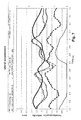
- FIG. 19 shows a running stride, for which a circuit board with the acceleration sensor 11 and rotational angle sensor 12 was attached to the heel cap. Markers were also provided on the heel cap so that the space coordinates could be identified by means of five IR cameras. From the position of the markers in space, the angle of the heel cap was calculated in three planes of projection: During the standing phase, the projection to the side wall (angle to wall) and the projection to the floor (angle to floor) correspond to the rotation in the pronation direction 2 , whereas the projection to the front wall (angle to front) corresponds to the rotation in the sagittal plane. The vertical acceleration was obtained from the sensor 11 .
- the change in the angle was obtained by integration from the rotational speed sensor 12 , and after subtraction of 1 g, the angle was zeroed out at the time the center of pressure of the negative component of the vertical acceleration occurred.
- the zero point agrees with sufficient accuracy with the zero point of the pronation angle determined from the 3D video analysis of various runners.
- the angle at the time of foot strike is usually strongly negative ( ⁇ 13° in FIG. 19 ) and highly variable from stride to stride.
- a later point in the time during the standing phase is used for zeroing-out.
- push-off from the standing phase into the swing phase usually occurs by way of the MTC1 (capitulum of the first metatarsal).
- the time of push-off is determined by the change in the signal of the acceleration sensor at the heel cap of the shoe and characterizes the end of the standing phase (100%). If the foot was previously in a pronated position, then there will be considerable rotational movement back in the supination direction and vice versa.
- the change in the angle just before push-off is therefore an important factor in differentiating between supinators and overpronators. If the angle is set to zero in this range (80-85% of the standing phase), the change in the angle can be determined with a resolution of a few degrees.
- an additional sensor is used to measure the change in the center of pressure (COP) under the heel.
- COP center of pressure
- the COP is the center of the pressure distribution under the sole of the foot. It changes with the pronating movement.
- the position is measured only in the mediolateral direction under the heel during the initial pronation.
- the reference position or angle is determined by a measurement in the standing position. By comparison with the COP measurement during the running process, the time is determined at which the heel cap assumes the reference angle.
- the COP measurement is conducted by an FSR linear potentiometer.
- FSR force-sensing resistor
- sensors are thin and flexible. They change their electrical resistance as a function of the force being exerted on their active surface.
- FSR linear potentiometers make it possible not only to measure the pressure but also to determine the location at which the pressure is introduced. The spatial resolution is less than 1 mm. If the pressure is introduced simultaneously at several locations, the indicated position corresponds to the COP of the active force.
- the FSR linear potentiometer is attached under the heel in such a way that it is transverse to the running direction and thus allows a 1-dimensional determination of the COP during initial pronation.
- the FSR potentiometer is carried in a special measuring sock, which the test subject has previously put on.
- the contact of the sole of the shoe with the ground is used to determine an angle during each stride. What is determined is the time at which one or more parts of the sole are in contact with the ground. This time is used as a fixed reference point for the angle calculation.
- a switch or pressure transducer is attached underneath the sole in such a way that it reacts on contact with the ground.
- a flat film switch attached to the center line of the sole behind and under the heel is a suitable type of switch. The switch supplies a signal precisely as long as the rear heel area of the sole, during the initial pronation phase, is in full contact with the ground (middle position).
- FSR sensors which can determine the middle position on the basis of the time at which maximum pressure is detected.
- FSR sensors are suitable for this. They are attached to the centerline in the heel area in a manner similar to the switches.
- the distance between the sole or heel cap and the ground is used to determine an angle during each stride. Sensors which measure the distance between the measurement point and the ground are used for this purpose. These measurement points can be connected to the shoe or connected directly to the position of the rotational angle sensor or its holder. The distance can be measured by optical or capacitive means. From this absolute distance measurement, it is then possible to determine the relative position by comparison of several measurement points with each other.
- the position of the sole or heel cap with respect to the ground is determined on the basis of when the measurement values in the reference position reach a maximum or a minimum. In a preferred embodiment, this is achieved by installing a photosensor at one end of a narrow tube, while the other end points to the ground. A minimum is reached when the tube is vertical and is the shortest distance away from the ground.
- the capacitance between a measuring surface and the ground is determined. This value reaches a maximum when the surface is parallel to the ground at a given distance.
- Two separate sensor surfaces can also be used, which, for example, are attached to the inner and outer sides of the shoe or sensor holder (of sensors 11 and 12 ). When the foot strikes the ground, first the outer and then the inner capacitance is affected. The position of the sole of the shoe can then be determined from the ratio between these two values.
- the position is determined by means of the Earth's magnetic field.
- the field is detected and evaluated by means of a 3D sensor.
Abstract
Description
R=B −1 *A [1]
where R is the vector of the transformed acceleration values in the three desired directions; A is the vector of the acceleration values in the three original directions, * is the matrix multiplier, and B−1 is the inverse of matrix B, where B is formed from the base values of the desired directions (R1, R2, R3 in
X=Z×H [2].
Y=X×Z [3].
X′=X/lX [4]
Y′=Y/lY [5]
Z′=Z/lZ [6],
where l is the length of the vector and is calculated as the square root of the sum of the squares of the components.
B=(X′,Y′,Z′) [7].
B −1 =B T=(X′,Y′,Z′)T [8].
Claims (13)
Applications Claiming Priority (4)
| Application Number | Priority Date | Filing Date | Title |
|---|---|---|---|
| DE102005004086A DE102005004086A1 (en) | 2005-01-21 | 2005-01-21 | Device and method for detecting movement |
| DE102005004086 | 2005-01-21 | ||
| DE102005004086.1 | 2005-01-21 | ||
| PCT/EP2006/000423 WO2006077104A1 (en) | 2005-01-21 | 2006-01-19 | Method and device for evaluating displacement signals |
Publications (2)
| Publication Number | Publication Date |
|---|---|
| US20080133171A1 US20080133171A1 (en) | 2008-06-05 |
| US7912672B2 true US7912672B2 (en) | 2011-03-22 |
Family
ID=36021737
Family Applications (1)
| Application Number | Title | Priority Date | Filing Date |
|---|---|---|---|
| US11/795,828 Expired - Fee Related US7912672B2 (en) | 2005-01-21 | 2006-01-19 | Method and device for evaluating displacement signals |
Country Status (4)
| Country | Link |
|---|---|
| US (1) | US7912672B2 (en) |
| EP (1) | EP1851511B1 (en) |
| DE (1) | DE102005004086A1 (en) |
| WO (1) | WO2006077104A1 (en) |
Cited By (14)
| Publication number | Priority date | Publication date | Assignee | Title |
|---|---|---|---|---|
| US20110140897A1 (en) * | 2011-02-16 | 2011-06-16 | Connor Kent Purks | Circuits, systems, and methods for monitoring and reporting foot impact, foot placement, shoe life, and other running/walking characteristics |
| US8573982B1 (en) | 2011-03-18 | 2013-11-05 | Thomas C. Chuang | Athletic performance and technique monitoring |
| US9095251B2 (en) | 2011-02-16 | 2015-08-04 | Bryce Benjamin Purks | Circuits, systems, and methods for monitoring and coaching a person's sideways spacing foot placement and roll, shoe life, and other running/walking characteristics |
| US9227108B1 (en) | 2011-04-14 | 2016-01-05 | Thomas Chu-Shan Chuang | Athletic performance monitoring with overstride detection |
| WO2016120725A1 (en) | 2015-01-29 | 2016-08-04 | Ambiorun | Training device for determining timing of next training session |
| WO2017083502A1 (en) * | 2015-11-11 | 2017-05-18 | Milestone Sport, Ltd. | Devices and methods for determining step characteristics |
| US10172423B2 (en) | 2016-03-15 | 2019-01-08 | Nike, Inc. | Capacitive foot presence sensing devices for footwear |
| WO2020126809A1 (en) * | 2018-12-19 | 2020-06-25 | Werkman Hoofcare Bv | Method for equine motion analysis |
| US10881310B2 (en) | 2012-08-25 | 2021-01-05 | The Board Of Trustees Of The Leland Stanford Junior University | Motion artifact mitigation methods and devices for pulse photoplethysmography |
| US20210106870A1 (en) * | 2010-06-16 | 2021-04-15 | Myotest Sa | Integrated portable device and method implementing an accelerometer for detecting asymmetries in a movement of a user |
| US11026481B2 (en) | 2016-03-15 | 2021-06-08 | Nike, Inc. | Foot presence signal processing using velocity |
| US11064768B2 (en) | 2016-03-15 | 2021-07-20 | Nike, Inc. | Foot presence signal processing using velocity |
| WO2021176060A1 (en) * | 2020-03-06 | 2021-09-10 | Werkman Hoofcare Bv | Method for equine motion analysis |
| US11357290B2 (en) | 2016-03-15 | 2022-06-14 | Nike, Inc. | Active footwear sensor calibration |
Families Citing this family (14)
| Publication number | Priority date | Publication date | Assignee | Title |
|---|---|---|---|---|
| US7692322B2 (en) | 2004-02-27 | 2010-04-06 | Mitsubishi Heavy Industries, Ltd. | Wind turbine generator, active damping method thereof, and windmill tower |
| EP2120801B1 (en) | 2007-01-19 | 2018-04-11 | Victhom Laboratory Inc. | Reactive layer control system for prosthetic and orthotic devices |
| US8024026B2 (en) * | 2007-05-31 | 2011-09-20 | General Electric Company | Dynamic reference method and system for use with surgical procedures |
| DE102009031268A1 (en) | 2009-06-30 | 2011-01-13 | Fraunhofer-Gesellschaft zur Förderung der angewandten Forschung e.V. | Analyze movements of objects |
| JP5647240B2 (en) * | 2009-07-10 | 2014-12-24 | コーニンクレッカ フィリップス エヌ ヴェ | Fall prevention |
| US8915968B2 (en) * | 2010-09-29 | 2014-12-23 | össur hf | Prosthetic and orthotic devices and methods and systems for controlling the same |
| US9060884B2 (en) | 2011-05-03 | 2015-06-23 | Victhom Human Bionics Inc. | Impedance simulating motion controller for orthotic and prosthetic applications |
| JP5557296B2 (en) * | 2011-08-22 | 2014-07-23 | 株式会社タニタ | Speed calculation method, speed calculation device, and computer program |
| US9044346B2 (en) | 2012-03-29 | 2015-06-02 | össur hf | Powered prosthetic hip joint |
| US9121863B2 (en) * | 2013-09-19 | 2015-09-01 | Honeywell International Inc. | Systems and methods for a limb strike detector |
| DE102017012056A1 (en) | 2016-12-30 | 2018-07-05 | Suunto Oy | PORTABLE CLOTHING PIECE AND SYSTEM AND METHOD FOR DETERMINING THE SUPPORT PROVIDED BY A PORTABLE CLOTHING PIECE |
| CN109757826B (en) * | 2019-03-04 | 2023-05-26 | 温州市质量技术监督检测院 | Method for testing stability of shoe |
| DE102019112126A1 (en) * | 2019-05-09 | 2020-11-12 | Moio Gmbh | Sensor module, care set and use therefor |
| TWI736286B (en) * | 2020-05-26 | 2021-08-11 | 國立清華大學 | Gait analysis-based imbalance early-warning method and wearable device |
Citations (6)
| Publication number | Priority date | Publication date | Assignee | Title |
|---|---|---|---|---|
| US5181181A (en) | 1990-09-27 | 1993-01-19 | Triton Technologies, Inc. | Computer apparatus input device for three-dimensional information |
| US6305221B1 (en) | 1995-12-12 | 2001-10-23 | Aeceleron Technologies, Llc | Rotational sensor system |
| US20030014210A1 (en) | 1994-11-21 | 2003-01-16 | Vock Curtis A. | Sport monitoring systems and associated methods |
| US6513381B2 (en) | 1997-10-14 | 2003-02-04 | Dynastream Innovations, Inc. | Motion analysis system |
| US6658292B2 (en) | 2001-08-24 | 2003-12-02 | Pacesetter, Inc. | Detection of patient's position and activity status using 3D accelerometer-based position sensor |
| WO2004072579A1 (en) | 2003-02-14 | 2004-08-26 | Akebono Brake Industry Co., Ltd. | Difference correcting method for posture determining instrument and motion measuring instrument |
-
2005
- 2005-01-21 DE DE102005004086A patent/DE102005004086A1/en not_active Withdrawn
-
2006
- 2006-01-19 US US11/795,828 patent/US7912672B2/en not_active Expired - Fee Related
- 2006-01-19 EP EP06703886.9A patent/EP1851511B1/en not_active Not-in-force
- 2006-01-19 WO PCT/EP2006/000423 patent/WO2006077104A1/en active Application Filing
Patent Citations (6)
| Publication number | Priority date | Publication date | Assignee | Title |
|---|---|---|---|---|
| US5181181A (en) | 1990-09-27 | 1993-01-19 | Triton Technologies, Inc. | Computer apparatus input device for three-dimensional information |
| US20030014210A1 (en) | 1994-11-21 | 2003-01-16 | Vock Curtis A. | Sport monitoring systems and associated methods |
| US6305221B1 (en) | 1995-12-12 | 2001-10-23 | Aeceleron Technologies, Llc | Rotational sensor system |
| US6513381B2 (en) | 1997-10-14 | 2003-02-04 | Dynastream Innovations, Inc. | Motion analysis system |
| US6658292B2 (en) | 2001-08-24 | 2003-12-02 | Pacesetter, Inc. | Detection of patient's position and activity status using 3D accelerometer-based position sensor |
| WO2004072579A1 (en) | 2003-02-14 | 2004-08-26 | Akebono Brake Industry Co., Ltd. | Difference correcting method for posture determining instrument and motion measuring instrument |
Non-Patent Citations (3)
| Title |
|---|
| Hansson G-A et al., "Validity and reliability of traxial accelerometers for inclinometry in posture analysis", Medical and Biological Engineering and Computing, Peter Peregrinus Ltd., vol. 39, No. 4, Jul. 2001, pp. 405-413. |
| Notification of Transmittal of Translation of the International Preliminary Report on Patentability dated Aug. 6, 2007 issued in corresponding application No. PCT/EP2006/000423. |
| W. Sun, W. Li, and Y, Xu, A MUMPs angular-position and angular-speed sensor with off chip wireless transmission, microsystem technology, 2001, p. 63-70. * |
Cited By (42)
| Publication number | Priority date | Publication date | Assignee | Title |
|---|---|---|---|---|
| US20210106870A1 (en) * | 2010-06-16 | 2021-04-15 | Myotest Sa | Integrated portable device and method implementing an accelerometer for detecting asymmetries in a movement of a user |
| US9616290B2 (en) * | 2011-02-16 | 2017-04-11 | Bryce Benjamin Purks | Foot monitoring system that generates an indication of how much shoe cushioning life remains in a shoe |
| US8581731B2 (en) * | 2011-02-16 | 2013-11-12 | Connor Kent Purks | Circuits, systems, and methods for monitoring and reporting foot impact, foot placement, shoe life, and other running/walking characteristics |
| US20110140897A1 (en) * | 2011-02-16 | 2011-06-16 | Connor Kent Purks | Circuits, systems, and methods for monitoring and reporting foot impact, foot placement, shoe life, and other running/walking characteristics |
| US9095251B2 (en) | 2011-02-16 | 2015-08-04 | Bryce Benjamin Purks | Circuits, systems, and methods for monitoring and coaching a person's sideways spacing foot placement and roll, shoe life, and other running/walking characteristics |
| US20150290496A1 (en) * | 2011-02-16 | 2015-10-15 | Bryce Benjamin Purks | Circuits, systems, and methods for monitoring and coaching a person's sideways spacing foot placement and roll, shoe life, and other running/walking characteristics |
| US10384098B1 (en) | 2011-03-18 | 2019-08-20 | Thomas C. Chuang | Relative directional energy expenditure |
| US8784274B1 (en) | 2011-03-18 | 2014-07-22 | Thomas C. Chuang | Athletic performance monitoring with body synchronization analysis |
| US9533182B1 (en) | 2011-03-18 | 2017-01-03 | Thomas C. Chuang | Athletic performance and technique monitoring |
| US9619698B1 (en) | 2011-03-18 | 2017-04-11 | Thomas C. Chuang | Athletic performance monitoring with body synchronization analysis |
| US10789708B1 (en) | 2011-03-18 | 2020-09-29 | Thomas C. Chuang | Athletic performance and technique monitoring |
| US8573982B1 (en) | 2011-03-18 | 2013-11-05 | Thomas C. Chuang | Athletic performance and technique monitoring |
| US9669259B1 (en) | 2011-03-18 | 2017-06-06 | Thomas C. Chuang | Athletic peformance and technique monitoring |
| US10049595B1 (en) | 2011-03-18 | 2018-08-14 | Thomas C. Chuang | Athletic performance and technique monitoring |
| US10143887B1 (en) | 2011-03-18 | 2018-12-04 | Thomas C. Chuang | Athletic peformance and technique monitoring |
| US11511154B1 (en) | 2011-03-18 | 2022-11-29 | Thomas Chuang | Athletic performance and technique monitoring |
| US10220254B1 (en) | 2011-03-18 | 2019-03-05 | Thomas C. Chuang | Multi-sensor body movement analysis |
| US11426630B1 (en) | 2011-04-14 | 2022-08-30 | Thomas C. Chuang | Stride change detection and correction |
| US10758778B1 (en) | 2011-04-14 | 2020-09-01 | Thomas Chu-Shan Chuang | Stride change detection and correction |
| US9227108B1 (en) | 2011-04-14 | 2016-01-05 | Thomas Chu-Shan Chuang | Athletic performance monitoring with overstride detection |
| US10881310B2 (en) | 2012-08-25 | 2021-01-05 | The Board Of Trustees Of The Leland Stanford Junior University | Motion artifact mitigation methods and devices for pulse photoplethysmography |
| WO2016120725A1 (en) | 2015-01-29 | 2016-08-04 | Ambiorun | Training device for determining timing of next training session |
| US10299702B2 (en) | 2015-11-11 | 2019-05-28 | Zwift, Inc. | Devices and methods for determining step characteristics |
| WO2017083502A1 (en) * | 2015-11-11 | 2017-05-18 | Milestone Sport, Ltd. | Devices and methods for determining step characteristics |
| US10477923B2 (en) | 2016-03-15 | 2019-11-19 | Nike, Inc. | Detector system for use with footwear |
| US10172423B2 (en) | 2016-03-15 | 2019-01-08 | Nike, Inc. | Capacitive foot presence sensing devices for footwear |
| US10722000B2 (en) | 2016-03-15 | 2020-07-28 | Nike, Inc. | Dynamic fit footwear |
| US11925239B2 (en) | 2016-03-15 | 2024-03-12 | Nike, Inc. | Foot presence sensing systems for active footwear |
| US10499711B2 (en) | 2016-03-15 | 2019-12-10 | Nike, Inc. | Capacitive foot presence sensing for footwear |
| US11026481B2 (en) | 2016-03-15 | 2021-06-08 | Nike, Inc. | Foot presence signal processing using velocity |
| US11044967B2 (en) | 2016-03-15 | 2021-06-29 | Nike, Inc. | Foot presence sensing using magnets in footwear |
| US11064768B2 (en) | 2016-03-15 | 2021-07-20 | Nike, Inc. | Foot presence signal processing using velocity |
| US11071355B2 (en) | 2016-03-15 | 2021-07-27 | Nike, Inc. | Foot presence signal processing systems and methods |
| US11889900B2 (en) | 2016-03-15 | 2024-02-06 | Nike, Inc. | Capacitive foot presence sensing for footwear |
| US11213100B2 (en) | 2016-03-15 | 2022-01-04 | Nike, Inc. | Foot presence sensing systems for active footwear |
| US11357290B2 (en) | 2016-03-15 | 2022-06-14 | Nike, Inc. | Active footwear sensor calibration |
| US10448707B2 (en) | 2016-03-15 | 2019-10-22 | Nike, Inc. | Capacitive foot presence sensing for footwear |
| US10758012B2 (en) | 2016-03-15 | 2020-09-01 | Nike, Inc. | Sensing device for footwear |
| US11766095B2 (en) | 2016-03-15 | 2023-09-26 | Nike, Inc. | Foot presence signal processing using velocity |
| US11857029B2 (en) | 2016-03-15 | 2024-01-02 | Nike, Inc. | Foot presence signal processing systems and methods |
| WO2020126809A1 (en) * | 2018-12-19 | 2020-06-25 | Werkman Hoofcare Bv | Method for equine motion analysis |
| WO2021176060A1 (en) * | 2020-03-06 | 2021-09-10 | Werkman Hoofcare Bv | Method for equine motion analysis |
Also Published As
| Publication number | Publication date |
|---|---|
| EP1851511A1 (en) | 2007-11-07 |
| EP1851511B1 (en) | 2016-03-16 |
| WO2006077104A1 (en) | 2006-07-27 |
| US20080133171A1 (en) | 2008-06-05 |
| DE102005004086A1 (en) | 2006-07-27 |
Similar Documents
| Publication | Publication Date | Title |
|---|---|---|
| US7912672B2 (en) | Method and device for evaluating displacement signals | |
| US6836744B1 (en) | Portable system for analyzing human gait | |
| US7057551B1 (en) | Electronic exercise monitor and method using a location determining component and a pedometer | |
| Morris et al. | Shoe-integrated sensor system for wireless gait analysis and real-time feedback | |
| JP6183906B2 (en) | Gait estimation device and program, fall risk calculation device and program | |
| US6356856B1 (en) | Method of and system for measuring performance during an exercise activity, and an athletic shoe for use in system | |
| CA2312640C (en) | Motion analysis system | |
| CA3022913C (en) | Instrumented orthotic | |
| US20080146968A1 (en) | Gait analysis system | |
| WO1998058236A1 (en) | System and method for measuring movement of objects | |
| CN102469959A (en) | Walking posture determination device | |
| US9943251B2 (en) | Stretch sensor device | |
| US20160220186A9 (en) | Detachable Wireless Motion System for Human Kinematic Analysis | |
| JP2020192307A (en) | Lower limb muscle strength evaluation method, lower limb muscle strength evaluation program, lower limb muscle strength evaluation device, and lower limb muscle strength evaluation system | |
| KR20210031178A (en) | Gait Analysis System Using Smart Insole | |
| US20110035185A1 (en) | Sensor-based Tracking of Variable Locomotion | |
| WO2015121690A1 (en) | Device apt for measuring physical efficiency and power output of human running, walking and other movements in watts and a method for its usage, application and processes | |
| KR102229071B1 (en) | Apparatus for implementing motion using piezoelectric sensor and method thereof | |
| WO2023127013A1 (en) | Static balance estimation device, static balance estimation system, static balance estimation method, and recording medium | |
| US20240115164A1 (en) | Detection device, detection method, and program recording medium | |
| US20240108249A1 (en) | Detection device, detection method, and program recording medium | |
| US20240122531A1 (en) | Index value estimation device, estimation system, index value estimation method, and recording medium | |
| US20240115163A1 (en) | Calculation device, calculation method, and program recording medium | |
| US20240108251A1 (en) | Calculation device, calculation method, and program recording medium | |
| US20240115162A1 (en) | Calculation device, calculation method, and program recording medium |
Legal Events
| Date | Code | Title | Description |
|---|---|---|---|
| AS | Assignment |
Owner name: XYBERMIND GMBH, GERMANY Free format text: ASSIGNMENT OF ASSIGNORS INTEREST;ASSIGNORS:FEICHTINGER, RICHARD;LOSCHINGER, JURGEN;REEL/FRAME:019655/0268 Effective date: 20070630 |
|
| AS | Assignment |
Owner name: HUMOTION GMBH, GERMANY Free format text: ASSIGNMENT OF ASSIGNORS INTEREST;ASSIGNOR:XYBERMIND GMBH;REEL/FRAME:025617/0774 Effective date: 20110105 |
|
| STCF | Information on status: patent grant |
Free format text: PATENTED CASE |
|
| AS | Assignment |
Owner name: XYBERMIND GMBH, GERMANY Free format text: ASSIGNMENT OF ASSIGNORS INTEREST;ASSIGNOR:HUMOTION GMBH;REEL/FRAME:028418/0320 Effective date: 20120522 |
|
| FPAY | Fee payment |
Year of fee payment: 4 |
|
| MAFP | Maintenance fee payment |
Free format text: PAYMENT OF MAINTENANCE FEE, 8TH YR, SMALL ENTITY (ORIGINAL EVENT CODE: M2552); ENTITY STATUS OF PATENT OWNER: SMALL ENTITY Year of fee payment: 8 |
|
| FEPP | Fee payment procedure |
Free format text: MAINTENANCE FEE REMINDER MAILED (ORIGINAL EVENT CODE: REM.); ENTITY STATUS OF PATENT OWNER: SMALL ENTITY |
|
| LAPS | Lapse for failure to pay maintenance fees |
Free format text: PATENT EXPIRED FOR FAILURE TO PAY MAINTENANCE FEES (ORIGINAL EVENT CODE: EXP.); ENTITY STATUS OF PATENT OWNER: SMALL ENTITY |
|
| STCH | Information on status: patent discontinuation |
Free format text: PATENT EXPIRED DUE TO NONPAYMENT OF MAINTENANCE FEES UNDER 37 CFR 1.362 |
|
| FP | Lapsed due to failure to pay maintenance fee |
Effective date: 20230322 |