US7887308B2 - Volumetric pump with reciprocated and rotated piston - Google Patents
Volumetric pump with reciprocated and rotated piston Download PDFInfo
- Publication number
- US7887308B2 US7887308B2 US11/718,369 US71836905A US7887308B2 US 7887308 B2 US7887308 B2 US 7887308B2 US 71836905 A US71836905 A US 71836905A US 7887308 B2 US7887308 B2 US 7887308B2
- Authority
- US
- United States
- Prior art keywords
- piston
- volumetric pump
- disc
- pump according
- housing
- Prior art date
- Legal status (The legal status is an assumption and is not a legal conclusion. Google has not performed a legal analysis and makes no representation as to the accuracy of the status listed.)
- Expired - Fee Related, expires
Links
Images


Classifications
-
- F—MECHANICAL ENGINEERING; LIGHTING; HEATING; WEAPONS; BLASTING
- F04—POSITIVE - DISPLACEMENT MACHINES FOR LIQUIDS; PUMPS FOR LIQUIDS OR ELASTIC FLUIDS
- F04B—POSITIVE-DISPLACEMENT MACHINES FOR LIQUIDS; PUMPS
- F04B19/00—Machines or pumps having pertinent characteristics not provided for in, or of interest apart from, groups F04B1/00 - F04B17/00
- F04B19/02—Machines or pumps having pertinent characteristics not provided for in, or of interest apart from, groups F04B1/00 - F04B17/00 having movable cylinders
- F04B19/022—Machines or pumps having pertinent characteristics not provided for in, or of interest apart from, groups F04B1/00 - F04B17/00 having movable cylinders reciprocating cylinders
-
- F—MECHANICAL ENGINEERING; LIGHTING; HEATING; WEAPONS; BLASTING
- F01—MACHINES OR ENGINES IN GENERAL; ENGINE PLANTS IN GENERAL; STEAM ENGINES
- F01C—ROTARY-PISTON OR OSCILLATING-PISTON MACHINES OR ENGINES
- F01C9/00—Oscillating-piston machines or engines
-
- F—MECHANICAL ENGINEERING; LIGHTING; HEATING; WEAPONS; BLASTING
- F04—POSITIVE - DISPLACEMENT MACHINES FOR LIQUIDS; PUMPS FOR LIQUIDS OR ELASTIC FLUIDS
- F04B—POSITIVE-DISPLACEMENT MACHINES FOR LIQUIDS; PUMPS
- F04B7/00—Piston machines or pumps characterised by having positively-driven valving
- F04B7/04—Piston machines or pumps characterised by having positively-driven valving in which the valving is performed by pistons and cylinders coacting to open and close intake or outlet ports
- F04B7/06—Piston machines or pumps characterised by having positively-driven valving in which the valving is performed by pistons and cylinders coacting to open and close intake or outlet ports the pistons and cylinders being relatively reciprocated and rotated
-
- F—MECHANICAL ENGINEERING; LIGHTING; HEATING; WEAPONS; BLASTING
- F04—POSITIVE - DISPLACEMENT MACHINES FOR LIQUIDS; PUMPS FOR LIQUIDS OR ELASTIC FLUIDS
- F04B—POSITIVE-DISPLACEMENT MACHINES FOR LIQUIDS; PUMPS
- F04B9/00—Piston machines or pumps characterised by the driving or driven means to or from their working members
- F04B9/02—Piston machines or pumps characterised by the driving or driven means to or from their working members the means being mechanical
- F04B9/04—Piston machines or pumps characterised by the driving or driven means to or from their working members the means being mechanical the means being cams, eccentrics or pin-and-slot mechanisms
-
- F—MECHANICAL ENGINEERING; LIGHTING; HEATING; WEAPONS; BLASTING
- F04—POSITIVE - DISPLACEMENT MACHINES FOR LIQUIDS; PUMPS FOR LIQUIDS OR ELASTIC FLUIDS
- F04C—ROTARY-PISTON, OR OSCILLATING-PISTON, POSITIVE-DISPLACEMENT MACHINES FOR LIQUIDS; ROTARY-PISTON, OR OSCILLATING-PISTON, POSITIVE-DISPLACEMENT PUMPS
- F04C9/00—Oscillating-piston machines or pumps
Definitions
- the present invention concerns a volumetric pump which may be used in different fields such as medical drug or fluid delivery (infusion Pump, IV pump, enteral pump, parenteral pump) or food, chemical or other industry, for example in conjunction with a compressor or an internal combustion engine.
- medical drug or fluid delivery infusion Pump, IV pump, enteral pump, parenteral pump
- food chemical or other industry, for example in conjunction with a compressor or an internal combustion engine.
- Piston pumps with fluid modules are already part of the prior art.
- US 2004/101426 discloses a device comprising a cylindrical piston chamber whose upper and lower ends' profile have a specific gradient, said piston chamber containing a rotatable and axially movable pump piston.
- the profile of the upper and lower end surfaces of the piston has been determined to run concomitantly in contact with the respective two end surfaces of the chamber as the piston rotates. This rotation causes the piston to move alternately upwards and downwards permitting one-way suction and one-way propulsion of a fluid respectively into and out of the pump chambers.
- the rotational movement of the piston acts as a valve opening and closing alternately the inlet and outlet ports.
- GB 2060131, U.S. Pat. Nos. 4,767,399 and 4,850,980 disclose a pumping mechanism device whose suction and propulsion phases are achieved by means of a bidirectional linear movement of a piston inside a chamber. Unlike US 2004/101426, such pumping mechanism has a device acting as a valve on the inlet/outlet ports which is independent of the piston's movement. Accordingly, the movement of the valve as well as its synchronization with the piston's movement requires more parts thus increasing the cost of the pumping mechanism.
- the aim of the present invention is to propose a low cost volumetric pump constituted of a reduced number of parts and having a trouble free assembly of the piston with the chamber.
- This aim is achieved by a volumetric pump as set out in claim 1 .
- This volumetric pump comprises at least one piston in a hollow cylinder, the pump having at least one inlet port through which a liquid can be sucked into a pump chamber during an instroke of said piston, and at least one outlet port through which the liquid can be expelled during an outstroke of the piston.
- the piston or the hollow cylinder can be actuated directly or indirectly by a rotor.
- This rotor transmits on the one hand a bi-directional linear movement to the piston or to the cylinder and on the other hand, a bi-directional angular movement either to the piston or to another rotable element in order to open and close alternately the inlet and outlet ports.
- the combined bidirectional linear and angular movement transmitted by the rotor has for consequence to deliver a steady fluid rate of flow from the volumetric pump.
- this volumetric pump is highly accurate as the amount of fluid delivered by said pump is closely related to the relative position between the piston and the hollow cylinder housing.
- FIG. 1 is a perspective view of a volumetric pump with a piston located in a hollow cylinder according to a first embodiment of the invention, with the rotor removed
- FIG. 2 is a perspective view of a rotor comprising an eccentric shaft of the first embodiment.
- FIG. 3 is a cross-sectional view showing the engagement of this eccentric shaft in a receptacle adjacent the top of the piston.
- FIG. 3 a shows a detail of FIG. 3 .
- FIG. 4 is a perspective view of the first embodiment of volumetric pump at the beginning of a revolution cycle of the rotor.
- FIG. 4 a is an axially sectioned rear view of FIG. 4 and FIG. 4 b is a cross-sectional view taken on the line A-A in FIG. 4 a.
- FIG. 5 is a perspective view of the volumetric pump after a 90° rotation of the rotor.
- FIG. 5 a is an axially sectioned rear view of FIG. 5 and FIG. 5 b is a cross-sectional view taken on the line A-A in FIG. 5 a.
- FIG. 6 is a perspective view the volumetric pump after a 180° rotation of the rotor.
- FIG. 6 a is an axially sectioned rear view of FIG. 6 and FIG. 6 b is a cross-sectional view taken on the line A-A in FIG. 6 a.
- FIG. 7 is a perspective view of the volumetric pump after a 270° rotation of the rotor.
- FIG. 7 a is an axially sectioned rear view of FIG. 7 and FIG. 7 b is a cross-sectional view taken on the line A-A in FIG. 7 a.
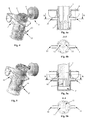
- FIG. 8 is a perspective view of the volumetric pump according to a second embodiment of the invention comprising a piston head.
- FIG. 8 a is a perspective view of said piston head connected to the shaft of the rotor.
- FIG. 8 b is a perspective view of the piston of the second embodiment of the invention.
- FIG. 9 is a perspective top view of the volumetric pump according to a third embodiment of the present invention showing the pump in transparency without the rotor.
- FIG. 9 a is a perspective bottom view of the third embodiment showing the outside of the volumetric pump without the rotor.
- FIG. 10 is a perspective view of one of the two cylindrical parts constituting the hollow cylindrical housing of the third embodiment.
- FIG. 10 a is a perspective view of another rotable element fitted into the cylindrical part of FIG. 10 .
- FIG. 11 is a front view of this rotable element and FIG. 11 a a cross-sectional view of said element taken on the line A-A in FIG. 11 .
- FIG. 12 a is an end view of FIG. 9 and FIG. 12 b a cross-sectional view taken on the line A-A in FIG. 12 a at the beginning of a cycle.
- FIG. 13 a is an end view of FIG. 9 and FIG. 13 b a cross-sectional view taken on the line A-A in FIG. 13 a after a 90° rotation of the rotor.
- FIG. 14 a is an end view of FIG. 9 and FIG. 14 b a cross-sectional view taken on the line A-A in FIG. 14 a after 180° rotation of the rotor.
- FIG. 15 a is an end view of FIG. 9 and FIG. 15 b a cross-sectional view taken on the line A-A in FIG. 15 a after 270° rotation of the rotor.
- FIG. 16 is a perspective view of the volumetric pump according to a fourth embodiment of the invention.
- FIG. 16 a is an axially sectioned view of FIG. 16 taken along an axe connected to a least one rotor.
- FIG. 17 is a perspective view of the volumetric pump according to a further embodiment of the invention.
- FIG. 17 a is an axially sectioned view of FIG. 17 taken along an axe connected to at least one rotor.
- FIG. 1 shows the volumetric pump ( 1 ) comprising a cylindrical piston ( 2 ) and a hollow cylinder ( 3 ) mounted on a support ( 4 ).
- This cylinder ( 3 ) has an upper open end wherein the piston ( 2 ) slidably fits.
- Piston ( 2 ) is actuated by a rotor ( 5 ) bearing an eccentric shaft ( 6 ) that is mounted on a spring ( 7 ).
- the shaft ( 6 ) ends with a spherical extremity ( 8 ) which is clipped into a piston receptacle ( 9 ) in order to transform the angular motion of the rotor ( 5 ) into a bi-directional linear and angular movement of the piston ( 2 ).
- This piston ( 2 ) slides to and fro inside the cylinder ( 3 ) while having a bi-directional angular movement.
- Shaft ( 6 ) transmits the movement of the piston ( 2 ) inside cylinder ( 3 ) as described below, while the spring ( 7 ) insures a smooth articulation of the extremity ( 8 ) inside the receptacle ( 9 ).
- Spring ( 7 ) is compressed when the piston ( 2 ) reaches the ends of the suction and propulsion strokes ( FIG. 4 and FIG. 6 ).
- the bidirectional angular movement of the piston ( 2 ) acts as a valve for inlet and outlet ports ( 10 , 11 ) that are located on opposite sides of the hollow cylinder ( 3 ).
- Piston ( 2 ) contains two channels ( 12 , 13 ), which cause the inlet port ( 10 ) and the outlet port ( 11 ) to open and close alternately while the piston ( 2 ) moves angularly.
- the instroke (or upstroke) of the piston ( 2 ) opens the inlet port ( 10 ) and closes the outlet port ( 11 ), sucking a fluid ( 15 ) from the inlet port ( 10 ) through the first channel ( 12 ) into the lower part of the hollow cylinder ( 3 ) ( FIG. 5 a and FIG. 5 b ).
- the outstroke (or down stroke) of the piston ( 2 ) closes the inlet port ( 10 ) and opens the outlet port ( 11 ), propelling the fluid ( 15 ) from said lower part of the pump chamber ( 3 ) through the second channel ( 13 ) to the outlet port ( 11 ) ( FIG. 7 a and FIG. 7 b ).
- Said channels ( 12 , 13 ) have been curve-shaped according to both bidirectional angular and linear movement of the piston ( 2 ) in order to ensure a constant opening of the inlet ( 10 ) and the outlet ( 11 ) during respectively the instroke phase and the outstroke phase of piston ( 2 ).
- This ensures a constant flow of liquid ( 15 ) from the inlet port ( 10 ) through the piston ( 2 ) to the lower part of the cylindrical chamber ( 3 ′) during the instroke of piston ( 2 ) and a constant flow of the liquid ( 15 ) from the lower part of the pump chamber ( 3 ′) to the outlet during the outstroke of the piston ( 2 ).
- gaskets or standard Orings ( 14 ) are positioned around the inlet port ( 10 ) and the outlet port ( 11 ) in order to seal off the existing play between the external diameter of the piston ( 2 ) and the internal diameter of the cylindrical chamber ( 3 ′).
- Said gaskets, which comprise specific sealing rib design, are part of the piston ( 2 ) or cylinder ( 3 ).
- the present invention may be adapted for medical use as a parenteral system.
- the piston ( 2 ) and the cylindrical chamber ( 3 ′) can constitute a disposable.
- the disposable piston ( 2 ) and cylindrical chamber ( 3 ′) can be produced by injection molding methods as hard plastic parts and are therefore not influenced by pressure and temperature.
- such system allows an accurate release of a specific amount of a drug by a preset angular shift of the rotor ( 5 ).
- a single dose is produced by a 360° rotation of said rotor ( 5 ).
- Several doses can be released with such system at fixed intervals of time by simply actuating the rotor.
- the upper-end of the piston ( 2 ) comprises a ball-and-socket joint ( 16 ) which is firmly connected to a piston head ( 17 ) through two lugs ( 18 ).
- the rotor ( 5 ) bearing the eccentric shaft ( 6 ) transmits through piston head ( 17 ) a combined bidirectional angular and linear movement to the piston ( 2 ), the piston head ( 17 ) having a hole into which a shaft ( 19 ) is driven in for guidance.
- Such embodiment avoids abutment which may occur in the first embodiment of the present invention between the spherical extremity ( 8 ) of the shaft ( 6 ) and the piston receptacle ( 9 ) when the piston ( 2 ) is in the suction or propulsion cycle as shown by FIG. 5 and FIG. 7 .
- a first and a second piston ( 20 , 21 ) are fixedly positioned opposite to each other inside a hollow cylindrical mobile housing ( 22 ) as shown by FIG. 9 .
- Said housing ( 22 ) is made up of two identical cylindrical parts ( 23 , 23 ′) assembled end-to-end facing each other.
- a disc ( 24 ) ( FIGS. 10 a , 11 , 11 a ) comprising the inlet and outlet ports ( 10 , 11 ) located preferably laterally at 180° from each other and a hole ( 25 ) on its underneath part ( FIG. 9 a ), is mounted midway inside said housing ( 22 ) between the two cylindrical parts ( 23 , 23 ′).
- Such assembling creates a first and a second chamber ( 26 , 26 ′) ( FIG. 12 b , 14 b ).
- the disc ( 24 ) is angularly movable relative to the housing ( 22 ) formed by parts ( 23 , 23 ′).
- a shaft (not shown) is inserted into the hole ( 25 ), said shaft being mounted on a rotor ( 5 ), as described in the first embodiment of the invention, for transmitting to the disc ( 24 ) a combined bi-directional linear and angular movement.
- Such movement of the disc ( 24 ) causes the cylindrical housing ( 22 ) to slide back and forth following the axis of the two pistons ( 20 , 21 ) while closing the inlet and outlet ports ( 10 , 11 ) so as to ensure on the one hand an alternate sucking of the fluid ( 15 ) from the inlet port ( 10 ) to respectively the first and second chamber ( 26 , 26 ′) and on the other hand an alternate expelling of the fluid ( 15 ) from respectively the first and second chambers ( 26 , 26 ′) to the outlet port ( 11 ).
- the optimum synchronization of the suction and propulsion phases between the two chambers ( 26 , 26 ′) is achieved by a first and a second T-shaped channel ( 27 , 27 ′) located inside the disc ( 24 ) and in its inlet/outlet as shown by FIG. 11 a .
- Channels ( 27 , 27 ′) connect alternately the inlet port ( 10 ) to the first and second chambers ( 26 , 26 ′,) and the first and the second chamber ( 26 , 26 ′) to the outlet port ( 11 ) when said channels ( 27 , 27 ′) overlap alternately the first and the second opening ( 28 , 28 ′) located on the end of both cylindrical parts ( 23 , 23 ′) ( FIG. 10 ).
- This particular embodiment of the invention allows the volumetric pump to provide a continuous flow.
- the combined bidirectional linear and angular movement of the piston ( 2 ) is imparted by mean of an axe ( 28 ) which passes through an upper part ( 29 ) rigidly connected with the piston head ( 17 ) as shown by FIGS. 16 and 16 a .
- Said axe ( 28 ) can be actuated by at least one rotor ( 5 ). The movement of the axe ( 28 ) transmits to the piston ( 2 ) a movement such as described in the second embodiment of the invention.
- Such transmission can be adapted to the third embodiment of the invention ( FIGS. 17 and 17 a ).
- the pump ( 1 ) is actuated by two rotors ( 5 , 5 ′) operatively connected to the upper and lower parts of said piston ( 2 ) as described in the first embodiment.
- the first rotor ( 5 ) transmits to the piston ( 2 ) the movement required by the suction phase while the second rotor ( 5 ′) transmits to said piston ( 2 ) the movement required by the propulsion phase.
- All embodiments of the present invention can be adapted so as to dissociate the relative linear movement of the piston with its angular movement.
- the linear movement can be transmitted by a first rotor and the angular movement can be transmitted by a second rotor.
- the movement of the piston can be converted from a linear movement to an angular movement at any time of its stroke.
- the pump ( 1 ) can be used as a compressor.
- a sealed tight tank can be fitted on the outlet port, sucking the air through the inlet ( 10 ) into the chamber and propelling the air into the tank by the same mechanism described in the first embodiment.
- this volumetric pump ( 1 ) can also be adapted for an internal combustion engine.
- another aspect of the invention is an internal combustion engine comprising a volumetric pump according to the invention, as described herein.
Abstract
Description
Claims (13)
Applications Claiming Priority (4)
| Application Number | Priority Date | Filing Date | Title |
|---|---|---|---|
| WOPCT/IB2004/003906 | 2004-11-29 | ||
| IBPCT/IB2004/003906 | 2004-11-29 | ||
| IB2004003906 | 2004-11-29 | ||
| PCT/IB2005/002423 WO2006056828A1 (en) | 2004-11-29 | 2005-08-12 | Volumetric pump with reciprocated and rotated piston |
Publications (2)
| Publication Number | Publication Date |
|---|---|
| US20090053086A1 US20090053086A1 (en) | 2009-02-26 |
| US7887308B2 true US7887308B2 (en) | 2011-02-15 |
Family
ID=35033304
Family Applications (2)
| Application Number | Title | Priority Date | Filing Date |
|---|---|---|---|
| US11/718,369 Expired - Fee Related US7887308B2 (en) | 2004-11-29 | 2005-08-12 | Volumetric pump with reciprocated and rotated piston |
| US12/822,593 Abandoned US20100260634A1 (en) | 2004-11-29 | 2010-06-24 | Volumetric Pump With Reciprocated and Rotated Piston |
Family Applications After (1)
| Application Number | Title | Priority Date | Filing Date |
|---|---|---|---|
| US12/822,593 Abandoned US20100260634A1 (en) | 2004-11-29 | 2010-06-24 | Volumetric Pump With Reciprocated and Rotated Piston |
Country Status (17)
| Country | Link |
|---|---|
| US (2) | US7887308B2 (en) |
| EP (2) | EP2107240B1 (en) |
| JP (1) | JP5085333B2 (en) |
| KR (1) | KR101177155B1 (en) |
| CN (2) | CN100582481C (en) |
| AT (2) | ATE411466T1 (en) |
| AU (1) | AU2005308558B2 (en) |
| BR (1) | BRPI0518085A (en) |
| CA (1) | CA2602052C (en) |
| DE (2) | DE602005010471D1 (en) |
| ES (1) | ES2359159T3 (en) |
| IL (1) | IL183337A (en) |
| MX (1) | MX2007006345A (en) |
| RU (1) | RU2377442C2 (en) |
| SG (1) | SG157414A1 (en) |
| WO (1) | WO2006056828A1 (en) |
| ZA (1) | ZA200705255B (en) |
Cited By (10)
| Publication number | Priority date | Publication date | Assignee | Title |
|---|---|---|---|---|
| US20110200456A1 (en) * | 2007-05-16 | 2011-08-18 | Smiths Medical Asd, Inc. | Pump module method for a medical fluid dispensing system |
| US20110206545A1 (en) * | 2008-10-30 | 2011-08-25 | Swissinnov Product Sarl | Volumetric pump and its driving mechanism |
| US20110208154A1 (en) * | 2007-03-15 | 2011-08-25 | Ulrich Haueter | Dosing device for an infusion system and method thereof |
| DE102012102273A1 (en) | 2012-03-19 | 2013-09-19 | B. Braun Melsungen Ag | Device for feeding and dosing a fluid for medical purposes |
| DE102012102274A1 (en) | 2012-03-19 | 2013-09-19 | B. Braun Melsungen Ag | piston pump |
| DE102012102272A1 (en) | 2012-03-19 | 2013-09-19 | B. Braun Melsungen Ag | Piston pump; Device for supplying and dosing a fluid for medical purposes by means of a piston pump |
| US9119911B2 (en) | 2008-09-12 | 2015-09-01 | Roche Diagnostics International Ag | Dosing unit, ambulatory infusion device comprising dosing unit and method for operating a dosing unit |
| US9649436B2 (en) | 2011-09-21 | 2017-05-16 | Bayer Healthcare Llc | Assembly method for a fluid pump device for a continuous multi-fluid delivery system |
| US10507319B2 (en) | 2015-01-09 | 2019-12-17 | Bayer Healthcare Llc | Multiple fluid delivery system with multi-use disposable set and features thereof |
| US11174852B2 (en) | 2018-07-20 | 2021-11-16 | Becton, Dickinson And Company | Reciprocating pump |
Families Citing this family (25)
| Publication number | Priority date | Publication date | Assignee | Title |
|---|---|---|---|---|
| US9433730B2 (en) | 2013-03-14 | 2016-09-06 | Bayer Healthcare Llc | Fluid mixing control device for a multi-fluid delivery system |
| US7766883B2 (en) | 2007-10-30 | 2010-08-03 | Medrad, Inc. | System and method for proportional mixing and continuous delivery of fluids |
| US9011377B2 (en) | 2008-11-05 | 2015-04-21 | Bayer Medical Care Inc. | Fluid mixing control device for a multi-fluid delivery system |
| NO325856B1 (en) | 2005-11-01 | 2008-08-04 | Hywind As | Method for damping unstable free rigid body oscillations in a floating wind turbine installation |
| SG172626A1 (en) * | 2006-06-02 | 2011-07-28 | Nomet Man Services B V | A volumetric pump comprising a driving mechanism |
| US20080039820A1 (en) * | 2006-08-10 | 2008-02-14 | Jeff Sommers | Medical Device With Septum |
| US8172799B2 (en) * | 2007-01-10 | 2012-05-08 | Acist Medical Systems, Inc. | Volumetric pump |
| US8425469B2 (en) * | 2007-04-23 | 2013-04-23 | Jacobson Technologies, Llc | Systems and methods for controlled substance delivery network |
| US8876765B2 (en) * | 2007-05-16 | 2014-11-04 | Smiths Medical Asd, Inc. | Pump module for use in a medical fluid dispensing system |
| EP2022982B1 (en) | 2007-07-23 | 2016-12-21 | ACIST Medical Systems, Inc. | Volumetric pump |
| WO2009076429A2 (en) | 2007-12-10 | 2009-06-18 | Medrad, Inc. | Continuous fluid delivery system and method |
| WO2010144533A1 (en) * | 2009-06-09 | 2010-12-16 | Jacobson Technologies, Llc | Controlled delivery of substances system and method |
| US20110021990A1 (en) * | 2009-07-23 | 2011-01-27 | Thierry Navarro | Micropump and method for manufacturing thereof |
| CA2767523A1 (en) * | 2009-07-23 | 2011-01-27 | Swissinnov Product Sarl | Fluid delivery system comprising a fluid pumping device and a drive system |
| US9511186B1 (en) | 2012-10-23 | 2016-12-06 | Acist Medical Systems, Inc. | Medical injection systems and pumps |
| DE102014002955A1 (en) * | 2013-03-19 | 2014-09-25 | Marquardt Mechatronik Gmbh | metering |
| FR3008745B1 (en) | 2013-07-22 | 2015-07-31 | Eveon | OSCILLO-ROTATING SUBASSEMBLY AND DEVICE FOR CO-INTEGRATED FLUID MULTIPLEXING AND VOLUMETRIC PUMPING OF A FLUID |
| WO2015041980A1 (en) | 2013-09-18 | 2015-03-26 | Smiths Medical Asd, Inc. | Pump device and method therefor of conveying fluid, and method of manufacturing the pump device |
| EP3099942B1 (en) * | 2014-01-31 | 2019-08-14 | Woodward, Inc. | Rotary piston type actuator |
| US20170234307A1 (en) * | 2014-03-02 | 2017-08-17 | Swissinnov Product Sarl | Volumetric pump with bleed mechanism |
| CN104948453B (en) * | 2014-03-26 | 2019-08-13 | 天津市石化通用机械研究所 | The pallet piston of crank link mechanism driving waves force feed fluid machine |
| FR3046358B1 (en) * | 2016-01-05 | 2020-12-04 | Ac&B | PROCESS AND DEVICE FOR MIXING COMPONENTS FOR THE MANUFACTURE OF A CUSTOM PRODUCT |
| EP3505757A1 (en) * | 2017-12-28 | 2019-07-03 | Sensile Medical AG | Micropump |
| WO2020208618A1 (en) * | 2019-04-10 | 2020-10-15 | Swissinnov Product Sarl | Positive displacement pump with single-axis drive mechanism |
| CN112274725B (en) * | 2020-12-24 | 2021-03-09 | 时新(上海)产品设计有限公司 | Medium infusion structure, medium infusion method, microdose secretion pump and insulin pump |
Citations (15)
| Publication number | Priority date | Publication date | Assignee | Title |
|---|---|---|---|---|
| US1238939A (en) | 1916-05-31 | 1917-09-04 | Raymond J Pfleeger | Oil-pump. |
| US1548981A (en) * | 1924-09-16 | 1925-08-11 | Clark Glenn | Double-acting suction and force pump |
| US2517645A (en) | 1947-07-11 | 1950-08-08 | Nathan Mfg Co | Pumping mechanism |
| GB860616A (en) * | 1958-01-14 | 1961-02-08 | Robert William Taylor M I B E | Improvements in reciprocating pumps |
| GB860606A (en) | 1957-11-26 | 1961-02-08 | Oerlikon Buehrle Ag | Improvements in and relating to the loading chambers of magazine rocket projectors |
| US3128782A (en) * | 1961-02-13 | 1964-04-14 | Alexander S Limpert | Small volume feeder pump and process of proportional feeding |
| GB2060131A (en) | 1979-09-06 | 1981-04-29 | Imed Corp | Pump Cassette for Controlled Intravenous Feed |
| US4767399A (en) | 1986-12-05 | 1988-08-30 | Fisher Scientific Group Inc. Dba Imed Corporation | Volumetric fluid withdrawal system |
| US4850980A (en) | 1987-12-04 | 1989-07-25 | Fisher Scientific Company | I.V. pump cassette |
| FR2668206A1 (en) | 1990-10-18 | 1992-04-24 | Gazaix Claude | Metering pumps with automatically controlled valves |
| US5312233A (en) | 1992-02-25 | 1994-05-17 | Ivek Corporation | Linear liquid dispensing pump for dispensing liquid in nanoliter volumes |
| WO1995008860A1 (en) | 1993-09-22 | 1995-03-30 | Exlar Corporation | Linear actuator with feedback position sensor device |
| US6358023B1 (en) * | 2000-08-23 | 2002-03-19 | Paul Guilmette | Moment pump |
| US20030210996A1 (en) * | 2002-05-09 | 2003-11-13 | Sergei Latyshev | Fluid machine |
| US20040101426A1 (en) | 2000-11-08 | 2004-05-27 | Andreas Wahlberg | Pump |
Family Cites Families (8)
| Publication number | Priority date | Publication date | Assignee | Title |
|---|---|---|---|---|
| GB191501865A (en) * | 1915-02-05 | 1915-08-12 | Oliver Howl | Improvements relating to Pumps. |
| US2092920A (en) * | 1936-02-06 | 1937-09-14 | Orlando B Johnson | Air pump |
| US3003428A (en) * | 1958-06-13 | 1961-10-10 | Gen Motors Corp | Pump |
| US3787145A (en) * | 1972-02-18 | 1974-01-22 | Beatrice Foods Co | Mixing pump assembly |
| JPS55108283U (en) * | 1979-01-23 | 1980-07-29 | ||
| FR2573487B1 (en) * | 1984-11-16 | 1988-11-18 | Elf Aquitaine | DOUBLE ACTING VOLUMETRIC PUMP |
| US4957419A (en) * | 1989-04-14 | 1990-09-18 | Rascov Anthony J | Compressor |
| JP2000145619A (en) | 1998-11-12 | 2000-05-26 | Aiteku Kk | Valveless pump |
-
2005
- 2005-08-12 BR BRPI0518085-6A patent/BRPI0518085A/en not_active IP Right Cessation
- 2005-08-12 EP EP08008711A patent/EP2107240B1/en not_active Not-in-force
- 2005-08-12 AT AT05771930T patent/ATE411466T1/en not_active IP Right Cessation
- 2005-08-12 AU AU2005308558A patent/AU2005308558B2/en not_active Ceased
- 2005-08-12 MX MX2007006345A patent/MX2007006345A/en active IP Right Grant
- 2005-08-12 JP JP2007542138A patent/JP5085333B2/en not_active Expired - Fee Related
- 2005-08-12 CN CN200580040166A patent/CN100582481C/en not_active Expired - Fee Related
- 2005-08-12 ES ES08008711T patent/ES2359159T3/en active Active
- 2005-08-12 WO PCT/IB2005/002423 patent/WO2006056828A1/en active Application Filing
- 2005-08-12 US US11/718,369 patent/US7887308B2/en not_active Expired - Fee Related
- 2005-08-12 DE DE602005010471T patent/DE602005010471D1/en active Active
- 2005-08-12 CN CNA2008101678026A patent/CN101429932A/en active Pending
- 2005-08-12 SG SG200907779-3A patent/SG157414A1/en unknown
- 2005-08-12 CA CA2602052A patent/CA2602052C/en not_active Expired - Fee Related
- 2005-08-12 RU RU2007120342/06A patent/RU2377442C2/en not_active IP Right Cessation
- 2005-08-12 AT AT08008711T patent/ATE491092T1/en active
- 2005-08-12 DE DE602005025265T patent/DE602005025265D1/en active Active
- 2005-08-12 EP EP05771930A patent/EP1817499B1/en not_active Not-in-force
- 2005-08-12 KR KR1020077014793A patent/KR101177155B1/en not_active IP Right Cessation
-
2007
- 2007-05-21 IL IL183337A patent/IL183337A/en not_active IP Right Cessation
- 2007-06-18 ZA ZA200705255A patent/ZA200705255B/en unknown
-
2010
- 2010-06-24 US US12/822,593 patent/US20100260634A1/en not_active Abandoned
Patent Citations (16)
| Publication number | Priority date | Publication date | Assignee | Title |
|---|---|---|---|---|
| US1238939A (en) | 1916-05-31 | 1917-09-04 | Raymond J Pfleeger | Oil-pump. |
| US1548981A (en) * | 1924-09-16 | 1925-08-11 | Clark Glenn | Double-acting suction and force pump |
| US2517645A (en) | 1947-07-11 | 1950-08-08 | Nathan Mfg Co | Pumping mechanism |
| GB860606A (en) | 1957-11-26 | 1961-02-08 | Oerlikon Buehrle Ag | Improvements in and relating to the loading chambers of magazine rocket projectors |
| GB860616A (en) * | 1958-01-14 | 1961-02-08 | Robert William Taylor M I B E | Improvements in reciprocating pumps |
| US3128782A (en) * | 1961-02-13 | 1964-04-14 | Alexander S Limpert | Small volume feeder pump and process of proportional feeding |
| GB2060131A (en) | 1979-09-06 | 1981-04-29 | Imed Corp | Pump Cassette for Controlled Intravenous Feed |
| US4767399A (en) | 1986-12-05 | 1988-08-30 | Fisher Scientific Group Inc. Dba Imed Corporation | Volumetric fluid withdrawal system |
| US4850980A (en) | 1987-12-04 | 1989-07-25 | Fisher Scientific Company | I.V. pump cassette |
| FR2668206A1 (en) | 1990-10-18 | 1992-04-24 | Gazaix Claude | Metering pumps with automatically controlled valves |
| US5312233A (en) | 1992-02-25 | 1994-05-17 | Ivek Corporation | Linear liquid dispensing pump for dispensing liquid in nanoliter volumes |
| WO1995008860A1 (en) | 1993-09-22 | 1995-03-30 | Exlar Corporation | Linear actuator with feedback position sensor device |
| US6358023B1 (en) * | 2000-08-23 | 2002-03-19 | Paul Guilmette | Moment pump |
| US20040101426A1 (en) | 2000-11-08 | 2004-05-27 | Andreas Wahlberg | Pump |
| US20030210996A1 (en) * | 2002-05-09 | 2003-11-13 | Sergei Latyshev | Fluid machine |
| US6793471B2 (en) * | 2002-05-09 | 2004-09-21 | Sergei Latyshev | Fluid machine |
Cited By (34)
| Publication number | Priority date | Publication date | Assignee | Title |
|---|---|---|---|---|
| US10034983B2 (en) | 2007-03-15 | 2018-07-31 | Roche Diabetes Care, Inc. | Dosing device for an infusion system and method thereof |
| US8790316B2 (en) | 2007-03-15 | 2014-07-29 | Roche Diagnostics International Ag | Dosing device for an infusion system and method thereof |
| US20110208154A1 (en) * | 2007-03-15 | 2011-08-25 | Ulrich Haueter | Dosing device for an infusion system and method thereof |
| US20110208127A1 (en) * | 2007-03-15 | 2011-08-25 | Ulrich Haueter | Dosing device for an infusion system and method thereof |
| US9687604B2 (en) | 2007-03-15 | 2017-06-27 | Roche Diagnostics International Ag | Dosing device for an infusion system and method thereof |
| US8277434B2 (en) * | 2007-03-15 | 2012-10-02 | Roche Diagnostics International Ag | Dosing device for an infusion system and method thereof |
| US8277423B2 (en) * | 2007-03-15 | 2012-10-02 | Roche Diagnostics International Ag | Dosing device for an infusion system and method thereof |
| US10034977B2 (en) | 2007-03-15 | 2018-07-31 | Roche Diabetes Care, Inc. | Dosing device for an infusion system and method thereof |
| US10029046B2 (en) | 2007-03-15 | 2018-07-24 | Roche Diabetes Care, Inc. | Dosing device for an infusion system and method thereof |
| US8142397B2 (en) * | 2007-05-16 | 2012-03-27 | Smiths Medical Asd, Inc. | Pump module method for a medical fluid dispensing system |
| US20110200456A1 (en) * | 2007-05-16 | 2011-08-18 | Smiths Medical Asd, Inc. | Pump module method for a medical fluid dispensing system |
| US9119911B2 (en) | 2008-09-12 | 2015-09-01 | Roche Diagnostics International Ag | Dosing unit, ambulatory infusion device comprising dosing unit and method for operating a dosing unit |
| US9022755B2 (en) * | 2008-10-30 | 2015-05-05 | Swissinnov Product Sarl | Volumetric pump and its driving mechanism |
| US20110206545A1 (en) * | 2008-10-30 | 2011-08-25 | Swissinnov Product Sarl | Volumetric pump and its driving mechanism |
| US9700672B2 (en) | 2011-09-21 | 2017-07-11 | Bayer Healthcare Llc | Continuous multi-fluid pump device, drive and actuating system and method |
| US9649436B2 (en) | 2011-09-21 | 2017-05-16 | Bayer Healthcare Llc | Assembly method for a fluid pump device for a continuous multi-fluid delivery system |
| DE102012102274A1 (en) | 2012-03-19 | 2013-09-19 | B. Braun Melsungen Ag | piston pump |
| US9937291B2 (en) | 2012-03-19 | 2018-04-10 | B. Braun Melsungen Ag | Piston pump |
| CN104204517B (en) * | 2012-03-19 | 2016-01-20 | B·布莱恩·梅尔松根股份公司 | Reciprocating pump, for supplying by means of reciprocating pump and measuring the device of the fluid for medical object |
| US9427517B2 (en) | 2012-03-19 | 2016-08-30 | B. Braun Melsungen Ag | Piston pump and device for feeding and metering a fluid for medical purposes by means of a piston pump |
| RU2602020C2 (en) * | 2012-03-19 | 2016-11-10 | Б. Браун Мельзунген Аг | Piston pump; device for feeding and dispensing of fluid medium for medical purposes using piston pump |
| CN104204517A (en) * | 2012-03-19 | 2014-12-10 | B·布莱恩·梅尔松根股份公司 | Piston pump, device for feeding and metering a fluid for medical purposes by means of a piston pump |
| WO2013139408A1 (en) | 2012-03-19 | 2013-09-26 | B. Braun Melsungen Ag | Device for supplying and metering a fluid for medicinal purposes |
| WO2013139629A1 (en) * | 2012-03-19 | 2013-09-26 | B. Braun Melsungen Ag | Piston pump |
| US9757517B2 (en) * | 2012-03-19 | 2017-09-12 | B. Braun Melsungen Ag | Piston pump |
| US20150064036A1 (en) * | 2012-03-19 | 2015-03-05 | B. Braun Melsungen Ag | Piston pump |
| DE102012102274B4 (en) | 2012-03-19 | 2018-05-24 | B. Braun Melsungen Ag | piston pump |
| WO2013139630A1 (en) * | 2012-03-19 | 2013-09-26 | B. Braun Melsungen Ag | Piston pump; device for feeding and metering a fluid for medical purposes by means of a piston pump |
| DE102012102272A1 (en) | 2012-03-19 | 2013-09-19 | B. Braun Melsungen Ag | Piston pump; Device for supplying and dosing a fluid for medical purposes by means of a piston pump |
| DE102012102273A1 (en) | 2012-03-19 | 2013-09-19 | B. Braun Melsungen Ag | Device for feeding and dosing a fluid for medical purposes |
| US10300192B2 (en) | 2012-03-19 | 2019-05-28 | B. Braun Melsungen Ag | Device for supplying and metering a fluid for medicinal purposes |
| US10507319B2 (en) | 2015-01-09 | 2019-12-17 | Bayer Healthcare Llc | Multiple fluid delivery system with multi-use disposable set and features thereof |
| US11491318B2 (en) | 2015-01-09 | 2022-11-08 | Bayer Healthcare Llc | Multiple fluid delivery system with multi-use disposable set and features thereof |
| US11174852B2 (en) | 2018-07-20 | 2021-11-16 | Becton, Dickinson And Company | Reciprocating pump |
Also Published As
| Publication number | Publication date |
|---|---|
| US20100260634A1 (en) | 2010-10-14 |
| KR20070092244A (en) | 2007-09-12 |
| BRPI0518085A (en) | 2008-10-28 |
| AU2005308558A1 (en) | 2006-06-01 |
| EP1817499B1 (en) | 2008-10-15 |
| EP2107240B1 (en) | 2010-12-08 |
| RU2007120342A (en) | 2009-01-10 |
| SG157414A1 (en) | 2009-12-29 |
| DE602005025265D1 (en) | 2011-01-20 |
| ATE491092T1 (en) | 2010-12-15 |
| ZA200705255B (en) | 2008-06-25 |
| JP2008522075A (en) | 2008-06-26 |
| EP2107240A2 (en) | 2009-10-07 |
| CA2602052A1 (en) | 2006-06-01 |
| MX2007006345A (en) | 2007-10-19 |
| US20090053086A1 (en) | 2009-02-26 |
| RU2377442C2 (en) | 2009-12-27 |
| CN101065577A (en) | 2007-10-31 |
| KR101177155B1 (en) | 2012-08-24 |
| CN100582481C (en) | 2010-01-20 |
| IL183337A (en) | 2012-02-29 |
| EP1817499A1 (en) | 2007-08-15 |
| IL183337A0 (en) | 2007-09-20 |
| ES2359159T3 (en) | 2011-05-18 |
| CA2602052C (en) | 2013-02-26 |
| ATE411466T1 (en) | 2008-10-15 |
| JP5085333B2 (en) | 2012-11-28 |
| CN101429932A (en) | 2009-05-13 |
| WO2006056828A1 (en) | 2006-06-01 |
| EP2107240A3 (en) | 2009-12-09 |
| DE602005010471D1 (en) | 2008-11-27 |
| AU2005308558B2 (en) | 2010-11-18 |
Similar Documents
| Publication | Publication Date | Title |
|---|---|---|
| US7887308B2 (en) | Volumetric pump with reciprocated and rotated piston | |
| US8172799B2 (en) | Volumetric pump | |
| US8353688B2 (en) | Volumetric pump comprising a driving mechanism | |
| US9726172B2 (en) | Rotary-oscillating subassembly and rotary-oscillating volumetric pumping device for volumetrically pumping a fluid | |
| US9022755B2 (en) | Volumetric pump and its driving mechanism | |
| EP2022982B1 (en) | Volumetric pump |
Legal Events
| Date | Code | Title | Description |
|---|---|---|---|
| AS | Assignment |
Owner name: NOMET MANAGEMENT SERVICES B.V.,NETHERLANDS Free format text: ASSIGNMENT OF ASSIGNORS INTEREST;ASSIGNOR:NAVARRO, THIERRY;REEL/FRAME:024601/0364 Effective date: 20100607 Owner name: NOMET MANAGEMENT SERVICES B.V., NETHERLANDS Free format text: ASSIGNMENT OF ASSIGNORS INTEREST;ASSIGNOR:NAVARRO, THIERRY;REEL/FRAME:024601/0364 Effective date: 20100607 |
|
| FEPP | Fee payment procedure |
Free format text: PAYOR NUMBER ASSIGNED (ORIGINAL EVENT CODE: ASPN); ENTITY STATUS OF PATENT OWNER: LARGE ENTITY |
|
| AS | Assignment |
Owner name: SWISSINNOV PRODUCT SARL, SWITZERLAND Free format text: ASSIGNMENT OF ASSIGNORS INTEREST;ASSIGNOR:NOMET MANAGEMENT SERVICES B.V.;REEL/FRAME:025606/0188 Effective date: 20110110 |
|
| FPAY | Fee payment |
Year of fee payment: 4 |
|
| FEPP | Fee payment procedure |
Free format text: MAINTENANCE FEE REMINDER MAILED (ORIGINAL EVENT CODE: REM.); ENTITY STATUS OF PATENT OWNER: LARGE ENTITY |
|
| LAPS | Lapse for failure to pay maintenance fees |
Free format text: PATENT EXPIRED FOR FAILURE TO PAY MAINTENANCE FEES (ORIGINAL EVENT CODE: EXP.); ENTITY STATUS OF PATENT OWNER: LARGE ENTITY |
|
| STCH | Information on status: patent discontinuation |
Free format text: PATENT EXPIRED DUE TO NONPAYMENT OF MAINTENANCE FEES UNDER 37 CFR 1.362 |
|
| FP | Lapsed due to failure to pay maintenance fee |
Effective date: 20190215 |