US7878058B2 - Fluid monitoring apparatus and method - Google Patents
Fluid monitoring apparatus and method Download PDFInfo
- Publication number
- US7878058B2 US7878058B2 US11/940,610 US94061007A US7878058B2 US 7878058 B2 US7878058 B2 US 7878058B2 US 94061007 A US94061007 A US 94061007A US 7878058 B2 US7878058 B2 US 7878058B2
- Authority
- US
- United States
- Prior art keywords
- sensor
- fluid
- liquid
- type
- barge
- Prior art date
- Legal status (The legal status is an assumption and is not a legal conclusion. Google has not performed a legal analysis and makes no representation as to the accuracy of the status listed.)
- Expired - Fee Related, expires
Links
- 238000012544 monitoring process Methods 0.000 title claims abstract description 15
- 239000012530 fluid Substances 0.000 title abstract description 136
- 238000000034 method Methods 0.000 title abstract description 6
- 239000007788 liquid Substances 0.000 claims description 17
- 230000005484 gravity Effects 0.000 claims description 8
- 230000003287 optical effect Effects 0.000 claims description 2
- XLYOFNOQVPJJNP-UHFFFAOYSA-N water Substances O XLYOFNOQVPJJNP-UHFFFAOYSA-N 0.000 description 46
- 230000005540 biological transmission Effects 0.000 description 7
- 238000001514 detection method Methods 0.000 description 4
- 239000003990 capacitor Substances 0.000 description 3
- 230000008859 change Effects 0.000 description 3
- 238000010586 diagram Methods 0.000 description 3
- 238000007689 inspection Methods 0.000 description 3
- 239000000463 material Substances 0.000 description 3
- 238000004210 cathodic protection Methods 0.000 description 2
- 229910010293 ceramic material Inorganic materials 0.000 description 2
- 238000013461 design Methods 0.000 description 2
- 238000005259 measurement Methods 0.000 description 2
- VNWKTOKETHGBQD-UHFFFAOYSA-N methane Chemical compound C VNWKTOKETHGBQD-UHFFFAOYSA-N 0.000 description 2
- 239000000203 mixture Substances 0.000 description 2
- 230000003466 anti-cipated effect Effects 0.000 description 1
- 239000011449 brick Substances 0.000 description 1
- 230000001413 cellular effect Effects 0.000 description 1
- 239000004568 cement Substances 0.000 description 1
- 238000004891 communication Methods 0.000 description 1
- 230000001419 dependent effect Effects 0.000 description 1
- 239000000835 fiber Substances 0.000 description 1
- 239000011152 fibreglass Substances 0.000 description 1
- 230000003116 impacting effect Effects 0.000 description 1
- 238000012986 modification Methods 0.000 description 1
- 230000004048 modification Effects 0.000 description 1
- 239000003345 natural gas Substances 0.000 description 1
- 230000010355 oscillation Effects 0.000 description 1
- 230000000737 periodic effect Effects 0.000 description 1
- 230000008569 process Effects 0.000 description 1
- 238000012545 processing Methods 0.000 description 1
- 239000011150 reinforced concrete Substances 0.000 description 1
- 230000007704 transition Effects 0.000 description 1
- 239000002699 waste material Substances 0.000 description 1
Images


Classifications
-
- G—PHYSICS
- G01—MEASURING; TESTING
- G01F—MEASURING VOLUME, VOLUME FLOW, MASS FLOW OR LIQUID LEVEL; METERING BY VOLUME
- G01F23/00—Indicating or measuring liquid level or level of fluent solid material, e.g. indicating in terms of volume or indicating by means of an alarm
- G01F23/22—Indicating or measuring liquid level or level of fluent solid material, e.g. indicating in terms of volume or indicating by means of an alarm by measuring physical variables, other than linear dimensions, pressure or weight, dependent on the level to be measured, e.g. by difference of heat transfer of steam or water
- G01F23/24—Indicating or measuring liquid level or level of fluent solid material, e.g. indicating in terms of volume or indicating by means of an alarm by measuring physical variables, other than linear dimensions, pressure or weight, dependent on the level to be measured, e.g. by difference of heat transfer of steam or water by measuring variations of resistance of resistors due to contact with conductor fluid
- G01F23/246—Indicating or measuring liquid level or level of fluent solid material, e.g. indicating in terms of volume or indicating by means of an alarm by measuring physical variables, other than linear dimensions, pressure or weight, dependent on the level to be measured, e.g. by difference of heat transfer of steam or water by measuring variations of resistance of resistors due to contact with conductor fluid thermal devices
-
- G—PHYSICS
- G01—MEASURING; TESTING
- G01F—MEASURING VOLUME, VOLUME FLOW, MASS FLOW OR LIQUID LEVEL; METERING BY VOLUME
- G01F23/00—Indicating or measuring liquid level or level of fluent solid material, e.g. indicating in terms of volume or indicating by means of an alarm
- G01F23/22—Indicating or measuring liquid level or level of fluent solid material, e.g. indicating in terms of volume or indicating by means of an alarm by measuring physical variables, other than linear dimensions, pressure or weight, dependent on the level to be measured, e.g. by difference of heat transfer of steam or water
- G01F23/26—Indicating or measuring liquid level or level of fluent solid material, e.g. indicating in terms of volume or indicating by means of an alarm by measuring physical variables, other than linear dimensions, pressure or weight, dependent on the level to be measured, e.g. by difference of heat transfer of steam or water by measuring variations of capacity or inductance of capacitors or inductors arising from the presence of liquid or fluent solid material in the electric or electromagnetic fields
- G01F23/263—Indicating or measuring liquid level or level of fluent solid material, e.g. indicating in terms of volume or indicating by means of an alarm by measuring physical variables, other than linear dimensions, pressure or weight, dependent on the level to be measured, e.g. by difference of heat transfer of steam or water by measuring variations of capacity or inductance of capacitors or inductors arising from the presence of liquid or fluent solid material in the electric or electromagnetic fields by measuring variations in capacitance of capacitors
- G01F23/268—Indicating or measuring liquid level or level of fluent solid material, e.g. indicating in terms of volume or indicating by means of an alarm by measuring physical variables, other than linear dimensions, pressure or weight, dependent on the level to be measured, e.g. by difference of heat transfer of steam or water by measuring variations of capacity or inductance of capacitors or inductors arising from the presence of liquid or fluent solid material in the electric or electromagnetic fields by measuring variations in capacitance of capacitors mounting arrangements of probes
-
- G—PHYSICS
- G01—MEASURING; TESTING
- G01F—MEASURING VOLUME, VOLUME FLOW, MASS FLOW OR LIQUID LEVEL; METERING BY VOLUME
- G01F23/00—Indicating or measuring liquid level or level of fluent solid material, e.g. indicating in terms of volume or indicating by means of an alarm
- G01F23/22—Indicating or measuring liquid level or level of fluent solid material, e.g. indicating in terms of volume or indicating by means of an alarm by measuring physical variables, other than linear dimensions, pressure or weight, dependent on the level to be measured, e.g. by difference of heat transfer of steam or water
- G01F23/28—Indicating or measuring liquid level or level of fluent solid material, e.g. indicating in terms of volume or indicating by means of an alarm by measuring physical variables, other than linear dimensions, pressure or weight, dependent on the level to be measured, e.g. by difference of heat transfer of steam or water by measuring the variations of parameters of electromagnetic or acoustic waves applied directly to the liquid or fluent solid material
- G01F23/284—Electromagnetic waves
- G01F23/292—Light, e.g. infrared or ultraviolet
-
- G—PHYSICS
- G01—MEASURING; TESTING
- G01F—MEASURING VOLUME, VOLUME FLOW, MASS FLOW OR LIQUID LEVEL; METERING BY VOLUME
- G01F23/00—Indicating or measuring liquid level or level of fluent solid material, e.g. indicating in terms of volume or indicating by means of an alarm
- G01F23/22—Indicating or measuring liquid level or level of fluent solid material, e.g. indicating in terms of volume or indicating by means of an alarm by measuring physical variables, other than linear dimensions, pressure or weight, dependent on the level to be measured, e.g. by difference of heat transfer of steam or water
- G01F23/28—Indicating or measuring liquid level or level of fluent solid material, e.g. indicating in terms of volume or indicating by means of an alarm by measuring physical variables, other than linear dimensions, pressure or weight, dependent on the level to be measured, e.g. by difference of heat transfer of steam or water by measuring the variations of parameters of electromagnetic or acoustic waves applied directly to the liquid or fluent solid material
- G01F23/296—Acoustic waves
- G01F23/2962—Measuring transit time of reflected waves
-
- G—PHYSICS
- G01—MEASURING; TESTING
- G01F—MEASURING VOLUME, VOLUME FLOW, MASS FLOW OR LIQUID LEVEL; METERING BY VOLUME
- G01F23/00—Indicating or measuring liquid level or level of fluent solid material, e.g. indicating in terms of volume or indicating by means of an alarm
- G01F23/30—Indicating or measuring liquid level or level of fluent solid material, e.g. indicating in terms of volume or indicating by means of an alarm by floats
- G01F23/64—Indicating or measuring liquid level or level of fluent solid material, e.g. indicating in terms of volume or indicating by means of an alarm by floats of the free float type without mechanical transmission elements
- G01F23/68—Indicating or measuring liquid level or level of fluent solid material, e.g. indicating in terms of volume or indicating by means of an alarm by floats of the free float type without mechanical transmission elements using electrically actuated indicating means
- G01F23/683—Indicating or measuring liquid level or level of fluent solid material, e.g. indicating in terms of volume or indicating by means of an alarm by floats of the free float type without mechanical transmission elements using electrically actuated indicating means using electromechanically actuated indicating means
-
- G—PHYSICS
- G01—MEASURING; TESTING
- G01F—MEASURING VOLUME, VOLUME FLOW, MASS FLOW OR LIQUID LEVEL; METERING BY VOLUME
- G01F23/00—Indicating or measuring liquid level or level of fluent solid material, e.g. indicating in terms of volume or indicating by means of an alarm
- G01F23/30—Indicating or measuring liquid level or level of fluent solid material, e.g. indicating in terms of volume or indicating by means of an alarm by floats
- G01F23/76—Indicating or measuring liquid level or level of fluent solid material, e.g. indicating in terms of volume or indicating by means of an alarm by floats characterised by the construction of the float
-
- H—ELECTRICITY
- H02—GENERATION; CONVERSION OR DISTRIBUTION OF ELECTRIC POWER
- H02G—INSTALLATION OF ELECTRIC CABLES OR LINES, OR OF COMBINED OPTICAL AND ELECTRIC CABLES OR LINES
- H02G9/00—Installations of electric cables or lines in or on the ground or water
- H02G9/10—Installations of electric cables or lines in or on the ground or water in cable chambers, e.g. in manhole or in handhole
Definitions
- This invention relates to a system for measuring and detecting the presence of one or more fluids in an enclosed space and for transmitting that information. More specifically, the invention is directed to a system and apparatus for measuring the presence of water and dielectric fluid inside an enclosure such as a utility vault and transmitting that information to a remote location.
- Underground electrical distribution systems such as those located in urban areas and under streets utilize underground utility vaults or enclosures to install utility components, such as transformers, wires, conduits etc. Exposure of these components to the elements, such as water are a constant threat and concern to providers. Additionally, the presence of certain fluids in utility vaults may indicate problems or potential problems requiring immediate attention.
- the traditional method of detecting and monitoring fluid in underground utility vaults involves sending a work crew for an in-person inspection of the contents of each enclosure. This method is both time and labor intensive and extremely costly.
- One aspect of the invention is directed to a system for measuring the amount and type of at least one fluid present in an enclosed space.
- Another aspect of the invention relates to an apparatus comprising a first sensor for detecting a total volume of fluid; and a second sensor to determine the volume presence of a first fluid or a second fluid. Where a property of the first fluid is different from a property of the second fluid; and where the first and second fluids make up at least a portion of the total volume of fluid.
- the sensor head is comprised of a sensor body and sensor circuit.
- the sensor body is made from a material whose buoyancy allows it to float in the presence of water and sink in the presence of dielectric fluid.
- the sensor circuit utilizes parallel plate capacitors as the frequency-determining element of an oscillator circuit. The sensor circuit allows the sensor to detect the presence and type of fluid based on the resonant frequency of oscillators in the presence of a fluid.
- a utility vault or manhole monitoring systems comprising a first and second sensor, a processor, and a transmitter.
- the first sensor is located at or near the top of a manhole or utility vault and uses a sonar or similar device to determine the overall depth of fluid present in the enclosure.
- the second sensor is disposed in a “barge” that floats in the presence of water.
- the barge utilizes a series of parallel plate capacitors with open spaces between the plates to determine the presence of dielectric fluid and/or water.
- the manhole monitoring system also includes data storing and data transmission of the information it collects about the type and amount of fluid present, with the ability to transmit that information to a central location on a periodic basis.
- FIG. 1 shows a block diagram of an exemplary utility vault monitoring system in accordance with the invention.
- FIG. 2 shows a block diagram of an alternative embodiment of a utility vault monitoring system in accordance with the invention.
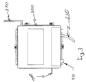
- FIG. 3 shows an exemplary external housing of a fixed assembly in accordance with the invention.
- FIG. 4 shows a exemplary schematic for use in a utility vault monitoring system in accordance with the invention.
- FIG. 5 shows a exemplary view of a sensor barge for use in accordance with the present invention.
- the present invention concerns a system and method for monitoring fluids inside an enclosure. More specifically the present invention relates to a utility vault or utility vault monitoring system comprising an assembly mounted at or near the ceiling of the utility vault and a floating assembly or barge that floats in the presence of water.
- the term utility vault refers to a room, typically underground, providing access to subterranean utility equipment, such as valves for water or natural gas pipes, or switchgear for electrical or telecommunications equipment.
- a utility vault is commonly constructed out of reinforced concrete, poured cement or brick. Small utility vaults are typically entered through a manhole or grate on the topside. Larger utility vaults are often similar to mechanical or electrical rooms in design and content.
- FIG. 1 shows representative components of a utility vault monitoring system.
- Item 200 represents a utility vault installed below street level 100 with street access via manhole 150 .
- Item 210 is an under ground conduit through which utility lines are run.
- Electronics assembly 30 is mounted to the side of the utility vault 200 and may house the necessary electronics to process and transmit the data to a central location.
- Sensor 40 is mounted to the utility vault at a location above conduit 210 and higher than the expected level of accumulated fluid 50 that might be in utility vault 200 .
- a second sensor 60 is located in such a manner as to be in contact with any accumulated fluid 50 .
- FIG. 2 shows a block diagram of an exemplary system in accordance with the invention.
- Item 200 represents an exemplary utility vault installed below street level 100 .
- Item 210 is an under ground conduit through which utility lines extend.
- Housing assembly 300 is mounted near the top of enclosure 200 that contains a processor 310 , batteries 320 , a wireless transmitter 330 , a circuit interface 340 , and sensors 400 , 500 and 700 .
- Fixed assembly 300 is mounted to the utility vault above conduit 210 in a location that is higher than the level of water or fluid that might accumulate in utility vault 200 .
- Sensor barge 600 houses a barge sensor 650 to detect the presence of fluid in utility vault 200 .
- Sensor barge 600 is located in proximity to sensor barge guide 640 in such a way as to allow sensor barge 600 to float freely upon water in utility vault 200 .
- Sensor barge guide 640 is mounted between the top and bottom of utility vault 200 .
- Sensor barge 600 is connected to the fixed assembly 300 via sensor umbilical cable 610 .
- Sensor umbilical cable 610 is connected to the circuit interface 340 located in fixed assembly 300 .
- Sensor umbilical cable 610 exits fixed assembly 300 and runs over pulley 630 down to sensor barge 600 .
- Pulley 630 is mounted to sensor barge guide 640 at a height approximately equal to or higher than fixed assembly 300 .
- Sensor umbilical cable weight 620 is located to provide constant downward force on sensor umbilical cable 610 . The constant downward force on sensor umbilical cable 610 keeps sensor umbilical cable 610 taught as sensor barge 600 rises up and down on the
- assembly 300 is a watertight enclosure large enough to house the required electrical components.
- An example of a suitable housing would be a National Electrical Manufacturers Association 4X fiberglass enclosure, although any enclosure of suitable size will be sufficient.
- FIG. 4 depicts an exemplary circuit for use in the assembly 300 .
- assembly 300 may include, for example, a processor 310 , a battery or series of batteries 320 , a cellular or wireless transmitter 330 , and interface circuitry 340 .
- Wireless transmitter 330 is connected to antenna 370 that is mounted to the external portion of fixed assembly 300 .
- FIG. 3 and 4 depict a single housing for processor 310 , batteries 320 , wireless transmitter 330 and interface circuitry 340 within an enclosed watertight assembly, it is readily understood that different housing configurations are usable in accordance with the invention, including omitting the housing itself.
- assembly 300 may further include a series of sensors.
- One such sensor is fluid sensor 400 , for example, a piezoelectric sensor that is used to determine the overall depth of the fluid present in utility vault 200 .
- Fluid sensor 400 allows calculation of water depth or dielectric fluid depth or a combination of both water and dielectric fluid.
- Fluid sensor 400 is comprised of a transducer 410 that converts electrical signals into acoustical signal.
- the transducer 410 of fluid sensor 400 may be mounted for example, on the bottom of fixed assembly 300 with the internal portion of fluid sensor 400 housed within fixed assembly 300 . In such an orientation, transducer 410 sends and receives sound pulses reflected off any fluid accumulated within utility vault 200 .
- the active component in transducer 410 may be a piezoelectric ceramic material. The ceramic material converts an electric transmit signal into a mechanical acoustic wave that travels through the air and reflects off of the bottom of the utility vault 200 . When the acoustic wave strikes any fluid in utility vault 200 , the signal is reflected back to the transducer and is converted back into an electric signal. By calculating the total travel time of the signal, the depth of any fluid present in utility vault 200 may be calculated. Any sensor type that detects the total depth or volume of fluid in a utility vault is usable in accordance with the invention. Suitable alternative sensor types include, sonar, thermal, pressure, and optical sensor configurations.
- Assembly 300 may also contain additional sensors, used to gather other information about the conditions in utility vault 200 .
- Typical sensors include a conduit temperature sensor 500 , a cathodic protection sensor 550 , and an ambient temperature sensor 700 , although other sensors may be utilized depending on the conditions a user wishes to monitor.
- FIG. 5 depicts an exemplary configuration for sensor barge 600 of FIG. 2 .
- sensor barge 600 is generally rectangular in shape having a length, width, and depth, although other shapes and geometries are possible. Cut out 605 allows sensor barge 600 to remain in proximity to sensor barge guide 640 as it rises and falls based on fluid level. It will be appreciated by those skilled in the art, that other shapes and configurations are usable in accordance with the invention without impacting the performance of the sensor, including designs that omit sensor guide 640 .
- sensor barge 600 is advantageously designed having a specific gravity lighter then water and heavier then dielectric fluid. Because the specific gravity of sensor barge 600 is lighter then water, but heavier than dielectric fluid, the sensor barge will float in the presence of water and will sink in the presence of dielectric fluid. When there is a mixture of water and dielectric fluid, but not enough dielectric fluid to completely cover sensor barge 600 , sensor barge 600 will float between the two. When the depth of dielectric fluid is greater than the thickness of sensor barge 600 , sensor barge 600 will completely submerge below the surface of the water.
- Air, water and dielectric fluid all have different dielectric constants. Air for example has a dielectric constant of 1.0, while water has a dielectric constant of 80.0, and most dielectric fluids and dielectric fluids have a dielectric constant value around 2.1. Relying on these differences, an electrical circuit can distinguish between the types of fluids filling the spaces between parallel metallic plates 131 to 138 of sensor barge 600 .
- An exemplary circuit configuration for use with sensor barge 600 is a series of parallel metallic plates 131 to 138 . Metallic plates 131 to 138 form capacitors with a capacitive value that is dependent upon the dielectric constant of the material in between the parallel metallic plates 131 to 138 .
- the parallel metallic plates 131 to 138 are connected via sensor umbilical cable 610 to oscillators 171 to 178 .
- oscillators 171 to 178 may be placed in the sensor barge 600 , thereby locating them in closer proximity to the parallel metallic plates 131 to 138 , and reducing capacitance generated by sensor umbilical cable 610 .
- a different resonant oscillation will be returned to microprocessor 310 .
- the circuit can determine if the sensor barge 600 is submerged in air, water, dielectric fluid or both.
- other sensor circuits that can distinguish a first fluid from a second fluid may be utilized without departing from the invention, including for example wheatstone bridges.
- a typical utility vault is 8 feet wide by 8 feet high by 17 feet long.
- Fixed assembly 300 , housing, processor 310 , batteries 320 , transmitter 330 and interface circuit 340 is mounted to one of the side walls of utility vault 200 .
- Fixed assembly 300 is positioned so that antenna 370 is located in close proximity to opening 150 and that transducer 410 is pointed in the downward direction toward the bottom of utility vault 200 .
- Sensor barge guide 640 is affixed between the top and bottom of utility vault 200 , thereby allowing sensor barge 600 to ride along sensor barge guide 640 as the fluid level in utility vault 200 increases.
- the system of an exemplary embodiment operates on battery power provided by batteries 320 located within fixed assembly 300 , however, alternative power sources may be utilized as will be appreciated by one skilled in the art, including, other suitable AC or DC power sources or from power lines connected to the local utility company.
- Processor 310 controls the operation of the system and has the ability to enter a low power consumption state, thereby conserving energy and prolonging the operation of the system. In operation, processor 310 intermittently or periodically, e.g., once a day, transmits the current operating conditions within utility vault 200 .
- processor 310 is a single integrated circuit that includes time counter 311 , a data formatter 312 , and analog to digital converters 313 .
- these components and functions may be included in a single IC chip or may be comprised of individual components or IC chips. Furthermore, as will be appreciated by one skilled in the art, these components may be housed within a single enclosure or multiple enclosures, or may even be mounted directly to utility vault 200 depending on the specific requirements of the space to be monitored.
- sensor 400 detects the total distance between the transducer 410 and the bottom of the utility vault 200 thereby indicating the absence of any appreciable amount of fluid.
- sensor barge 600 remains on the bottom of utility vault 200 there will be no fluid between the parallel metallic plates 131 to 138 . Accordingly, there will be no dielectric fluid or water detected and no information relative to fluid to report.
- the system may gather other information such as conduit temperature via sensor 500 , ambient temperature via sensor 700 , and cathodic protection via sensor 550 .
- This information is then conveyed via interface circuit 340 to processor 310 .
- the data may be stored in comma delimited files, or any other suitable format.
- processor 310 transitions from a standby state and conveys the stored information to wireless transmitter 330 .
- Wireless transmitter 330 transmits the information via antenna 370 to a transceiver equipped personal computer at a remote location.
- Wireless transmission may be carried out in a variety of formats such as GSM or CDMA, although GSM is preferred.
- modes of data transmission other than wireless may be used to transmit the data.
- Some exemplary modes include use of telephone lines, fiber optic transmission lines, cable television transmission lines data network links, or any other suitable form of communication line.
- Sensor 400 will detect the presence of fluid in utility vault 200 without making a determination of the presence of multiple fluids or the type of fluid.
- Transceiver 410 will transmit its acoustical signal towards the bottom of utility vault 200 and the signal will be reflected back to transceiver 410 in a shorter period of time then when there is no fluid present, thereby indicating the presence of fluid in utility vault 200 .
- Sensor 400 outputs a respective signal indicating a change in the depth of fluid without any indication as to the type and number of fluids present.
- the oscillators 171 to 178 will generate a signal at a particular frequency, i.e., a frequency previously associated with the dielectric constant for air.
- the signals from the respective oscillators, 171 - 178 are transmitted to multiplexer 618 and combined into a single multiplexed signal.
- the combined signal is transmitted to microprocessor 310 which de-multiplexes the signal and determines which if, any of the metallic plates 171 to 178 are in the presence of air, water or dielectric fluid.
- the gathered information may then be stored, collected, formatted, and/or transmitted in a like manner as described above. It is readily understood that the oscillator signals may be communicated without multiplexing in accordance with the invention.
- alternative sensor material are usable for detecting a difference in other characteristics of two or more fluids that may be present in the utility vault 200 , including, for example, sensors to measure the pH or specific gravity or conductivity of a particular fluid to determine the fluids presence and composition.
- sensor 400 directs an acoustical signal toward the bottom of utility vault 200 .
- the signal is reflected back to transceiver 410 in a shorter period of time than when there is no fluid present, thereby indicating the presence of fluid in utility vault 200 .
- Sensor 400 will output a respective signal to processor 310 indicating a change in the overall depth of fluid.
- Sensor barge 600 will remain in close proximity to sensor barge guide 640 but due to the specific gravity of sensor barge 600 , it will not float on the dielectric.
- sensor barge 600 does not float on dielectric fluid, the metallic plates 131 to 138 will directly contact the dielectric fluid depending on the depth of fluid present. Based on the depth of the dielectric fluid, some or all of the gaps between metallic plates 131 to 138 will be filled with dielectric fluid. Based on the dielectric constant of 2.1 for dielectric fluid, the oscillators 171 to 178 will generate signals at a particular frequency, i.e., a frequency previously associated with the dielectric constant for dielectric fluid. The respective oscillator signals from oscillators 171 to 178 will be multiplexed together in multiplexer 618 and the combined signal will be conveyed to microprocessor 310 .
- Microprocessor 310 will determine which, if any of the metallic plates are submerged in dielectric fluid and which are in air. The information will then be collected, stored, formatted, and/or transmitted in a like manner as described above. As with the detection of water only, it will be appreciated that alternative sensors and detection circuits may be utilized without departing from the spirit of the invention, furthermore, as noted above, it is readily understood that the oscillator signals may be communicated without multiplexing in accordance with the invention. For example, a sensor circuit could be incorporated into sensor barge guide 640 or sensor barge 600 might be equipped to detect a fluids property other than dielectric constant.
- sensor barge 600 When both water and dielectric fluid are present, sensor barge 600 , due to its specific gravity, will either float between the two fluids, or be submerged in the water depending on the amount of dielectric fluid present.
- sensor 400 When there is both water and dielectric fluid present in utility vault 200 , sensor 400 transmits its acoustical signal which in turn is reflected back to transceiver 410 in a shorter period of time then when there is no fluid present, thereby indicating the presence of fluid in utility vault 200 . Sensor 400 will output a respective signal indicating a change in the depth of fluid. Sensor barge 600 will remain in close proximity to sensor barge guide 640 and will rise in the water and dielectric fluid.
- sensor barge 600 When the depth of the dielectric fluid does not exceed the height of sensor barge 600 , sensor barge 600 will float between the two fluids. As a result, some of the metallic plates 131 to 138 may be submerged in water and some in dielectric fluid and others still in air. In this configuration, the oscillators 171 to 178 will resonate at different frequencies depending on which fluid their respective metallic plates are submerged in, i.e., air, water, or dielectric fluid. This frequency information of oscillators 171 to 178 may be multiplexed together in multiplexer 618 and conveyed to microprocessor 310 , which will determine if the particular metallic plate are in water, dielectric fluid, or air.
- the microprocessor 310 then formats the data and stores it for later transmission to the central location for further processing via wireless transmitter 330 .
- the microprocessor 310 may be preprogrammed, based on the number of metallic plates in water and the number in dielectric fluid, and the number in air, to output information directly relating to the amount of dielectric fluid present.
- microprocessor 310 may perform the necessary calculations to determine the amount of water and the amount of dielectric fluid present. This information can then be transmitted via wireless transmitter 330 to the central location. Based on inherent properties of the sensor barge 600 , and the geometry of the metallic plates 131 to 138 located in sensor barge 600 , the microprocessor can make very accurate determinations as to the amount of dielectric fluid present.
- the specific gravity of sensor barge 600 is specifically chosen to be lighter than water, and heavier than dielectric fluid.
- the sensor barge 600 will completely submerge in the water.
- the gaps in metallic plates 131 to 138 will all be filled with water causing the respective oscillators to resonate at a particular frequency previously associated with the presence of water.
- the information from the respective oscillators 171 to 178 is multiplexed together via multiplexer 618 and conveyed to microprocessor 310 .
- Microprocessor 310 may then transmit this information via wireless transmitter 330 to the central location
- sensor configurations may be implemented, that include, for example, sensors located at the bottom of utility vault 200 that can determine the depth between the bottom of the utility vault 200 and barge 600 , thereby measuring the level of water preset. Once the amount of water present is known, the amount of dielectric fluid can be computed based on the total amount of fluid present.
- various sensor barge configurations might be implemented to allow for more specific measurements. One such configuration might include a sensor barge that is thicker then the anticipated depth of the maximum expected dielectric fluid, a barge will never be completely submerged, thereby always indicating the exact amount of dielectric fluid present.
- Another configuration might include a vertical sensor configuration that continues for the entire height of the utility vault 200 , thereby including many more metallic plate pairs to allow for greater fluid depth measurements.
- alternative useful sensor configurations include any first sensor that identifies the total depth of the fluids present and a second sensor that detects a characteristic of a particular fluid that makes determination of the depth of the second fluid present possible.
Abstract
Description
Claims (8)
Priority Applications (1)
| Application Number | Priority Date | Filing Date | Title |
|---|---|---|---|
| US11/940,610 US7878058B2 (en) | 2007-11-15 | 2007-11-15 | Fluid monitoring apparatus and method |
Applications Claiming Priority (1)
| Application Number | Priority Date | Filing Date | Title |
|---|---|---|---|
| US11/940,610 US7878058B2 (en) | 2007-11-15 | 2007-11-15 | Fluid monitoring apparatus and method |
Publications (2)
| Publication Number | Publication Date |
|---|---|
| US20090126483A1 US20090126483A1 (en) | 2009-05-21 |
| US7878058B2 true US7878058B2 (en) | 2011-02-01 |
Family
ID=40640558
Family Applications (1)
| Application Number | Title | Priority Date | Filing Date |
|---|---|---|---|
| US11/940,610 Expired - Fee Related US7878058B2 (en) | 2007-11-15 | 2007-11-15 | Fluid monitoring apparatus and method |
Country Status (1)
| Country | Link |
|---|---|
| US (1) | US7878058B2 (en) |
Cited By (52)
| Publication number | Priority date | Publication date | Assignee | Title |
|---|---|---|---|---|
| US20080255613A1 (en) * | 2007-04-10 | 2008-10-16 | Biomet Sports Medicine, Inc. | Adjustable knotless loops |
| US8771316B2 (en) | 2006-02-03 | 2014-07-08 | Biomet Sports Medicine, Llc | Method and apparatus for coupling anatomical features |
| US8840645B2 (en) | 2004-11-05 | 2014-09-23 | Biomet Sports Medicine, Llc | Method and apparatus for coupling soft tissue to a bone |
| US8900314B2 (en) | 2009-05-28 | 2014-12-02 | Biomet Manufacturing, Llc | Method of implanting a prosthetic knee joint assembly |
| US8936621B2 (en) | 2006-02-03 | 2015-01-20 | Biomet Sports Medicine, Llc | Method and apparatus for forming a self-locking adjustable loop |
| US8968364B2 (en) | 2006-02-03 | 2015-03-03 | Biomet Sports Medicine, Llc | Method and apparatus for fixation of an ACL graft |
| US8998949B2 (en) | 2004-11-09 | 2015-04-07 | Biomet Sports Medicine, Llc | Soft tissue conduit device |
| US9005287B2 (en) | 2006-02-03 | 2015-04-14 | Biomet Sports Medicine, Llc | Method for bone reattachment |
| US9078644B2 (en) | 2006-09-29 | 2015-07-14 | Biomet Sports Medicine, Llc | Fracture fixation device |
| US9149267B2 (en) | 2006-02-03 | 2015-10-06 | Biomet Sports Medicine, Llc | Method and apparatus for coupling soft tissue to a bone |
| US9173651B2 (en) | 2006-02-03 | 2015-11-03 | Biomet Sports Medicine, Llc | Soft tissue repair device and associated methods |
| US9216078B2 (en) | 2011-05-17 | 2015-12-22 | Biomet Sports Medicine, Llc | Method and apparatus for tibial fixation of an ACL graft |
| US9271713B2 (en) | 2006-02-03 | 2016-03-01 | Biomet Sports Medicine, Llc | Method and apparatus for tensioning a suture |
| US9314241B2 (en) | 2011-11-10 | 2016-04-19 | Biomet Sports Medicine, Llc | Apparatus for coupling soft tissue to a bone |
| US9357991B2 (en) | 2011-11-03 | 2016-06-07 | Biomet Sports Medicine, Llc | Method and apparatus for stitching tendons |
| US9370350B2 (en) | 2011-11-10 | 2016-06-21 | Biomet Sports Medicine, Llc | Apparatus for coupling soft tissue to a bone |
| US9381013B2 (en) | 2011-11-10 | 2016-07-05 | Biomet Sports Medicine, Llc | Method for coupling soft tissue to a bone |
| US9402621B2 (en) | 2006-02-03 | 2016-08-02 | Biomet Sports Medicine, LLC. | Method for tissue fixation |
| US9414925B2 (en) | 2006-09-29 | 2016-08-16 | Biomet Manufacturing, Llc | Method of implanting a knee prosthesis assembly with a ligament link |
| US9414833B2 (en) | 2006-02-03 | 2016-08-16 | Biomet Sports Medicine, Llc | Soft tissue repair assembly and associated method |
| US9445827B2 (en) | 2011-10-25 | 2016-09-20 | Biomet Sports Medicine, Llc | Method and apparatus for intraosseous membrane reconstruction |
| US9486211B2 (en) | 2006-09-29 | 2016-11-08 | Biomet Sports Medicine, Llc | Method for implanting soft tissue |
| US9492158B2 (en) | 2006-02-03 | 2016-11-15 | Biomet Sports Medicine, Llc | Method and apparatus for coupling soft tissue to a bone |
| US9504460B2 (en) | 2004-11-05 | 2016-11-29 | Biomet Sports Medicine, LLC. | Soft tissue repair device and method |
| US9510819B2 (en) | 2006-02-03 | 2016-12-06 | Biomet Sports Medicine, Llc | Soft tissue repair device and associated methods |
| US9532777B2 (en) | 2006-02-03 | 2017-01-03 | Biomet Sports Medicine, Llc | Method and apparatus for coupling soft tissue to a bone |
| US9539003B2 (en) | 2006-09-29 | 2017-01-10 | Biomet Sports Medicine, LLC. | Method and apparatus for forming a self-locking adjustable loop |
| US9538998B2 (en) | 2006-02-03 | 2017-01-10 | Biomet Sports Medicine, Llc | Method and apparatus for fracture fixation |
| US9572655B2 (en) | 2004-11-05 | 2017-02-21 | Biomet Sports Medicine, Llc | Method and apparatus for coupling soft tissue to a bone |
| US9603591B2 (en) | 2006-02-03 | 2017-03-28 | Biomet Sports Medicine, Llc | Flexible anchors for tissue fixation |
| US9615822B2 (en) | 2014-05-30 | 2017-04-11 | Biomet Sports Medicine, Llc | Insertion tools and method for soft anchor |
| US9642661B2 (en) | 2006-02-03 | 2017-05-09 | Biomet Sports Medicine, Llc | Method and Apparatus for Sternal Closure |
| US9681940B2 (en) | 2006-09-29 | 2017-06-20 | Biomet Sports Medicine, Llc | Ligament system for knee joint |
| US9700291B2 (en) | 2014-06-03 | 2017-07-11 | Biomet Sports Medicine, Llc | Capsule retractor |
| US9724090B2 (en) | 2006-09-29 | 2017-08-08 | Biomet Manufacturing, Llc | Method and apparatus for attaching soft tissue to bone |
| US9757119B2 (en) | 2013-03-08 | 2017-09-12 | Biomet Sports Medicine, Llc | Visual aid for identifying suture limbs arthroscopically |
| US9763656B2 (en) | 2006-02-03 | 2017-09-19 | Biomet Sports Medicine, Llc | Method and apparatus for soft tissue fixation |
| US9788876B2 (en) | 2006-09-29 | 2017-10-17 | Biomet Sports Medicine, Llc | Fracture fixation device |
| US9797049B2 (en) | 2015-02-16 | 2017-10-24 | Electric Power Research Institute, Inc. | System, apparatus, and method of providing cathodic protection to buried and/or submerged metallic structures |
| US9801708B2 (en) | 2004-11-05 | 2017-10-31 | Biomet Sports Medicine, Llc | Method and apparatus for coupling soft tissue to a bone |
| US9801620B2 (en) | 2006-02-03 | 2017-10-31 | Biomet Sports Medicine, Llc | Method and apparatus for coupling soft tissue to bone |
| US9918827B2 (en) | 2013-03-14 | 2018-03-20 | Biomet Sports Medicine, Llc | Scaffold for spring ligament repair |
| US9918826B2 (en) | 2006-09-29 | 2018-03-20 | Biomet Sports Medicine, Llc | Scaffold for spring ligament repair |
| US9955980B2 (en) | 2015-02-24 | 2018-05-01 | Biomet Sports Medicine, Llc | Anatomic soft tissue repair |
| US10039543B2 (en) | 2014-08-22 | 2018-08-07 | Biomet Sports Medicine, Llc | Non-sliding soft anchor |
| US10136886B2 (en) | 2013-12-20 | 2018-11-27 | Biomet Sports Medicine, Llc | Knotless soft tissue devices and techniques |
| US10245214B2 (en) | 2010-04-27 | 2019-04-02 | Crisi Medical Systems, Inc. | Medication and identification information transfer apparatus |
| US10517587B2 (en) | 2006-02-03 | 2019-12-31 | Biomet Sports Medicine, Llc | Method and apparatus for forming a self-locking adjustable loop |
| US10912551B2 (en) | 2015-03-31 | 2021-02-09 | Biomet Sports Medicine, Llc | Suture anchor with soft anchor of electrospun fibers |
| US11259794B2 (en) | 2006-09-29 | 2022-03-01 | Biomet Sports Medicine, Llc | Method for implanting soft tissue |
| US11259792B2 (en) | 2006-02-03 | 2022-03-01 | Biomet Sports Medicine, Llc | Method and apparatus for coupling anatomical features |
| US11311287B2 (en) | 2006-02-03 | 2022-04-26 | Biomet Sports Medicine, Llc | Method for tissue fixation |
Families Citing this family (18)
| Publication number | Priority date | Publication date | Assignee | Title |
|---|---|---|---|---|
| US7889087B2 (en) * | 2008-10-06 | 2011-02-15 | International Business Machines Corporation | Immersion detection |
| US8085156B2 (en) * | 2009-04-08 | 2011-12-27 | Rosemount Inc. | RF cavity-based process fluid sensor |
| US9039655B2 (en) | 2009-11-06 | 2015-05-26 | Crisi Medical Systems, Inc. | Medication injection site and data collection system |
| US10492991B2 (en) | 2010-05-30 | 2019-12-03 | Crisi Medical Systems, Inc. | Medication container encoding, verification, and identification |
| US9514131B1 (en) | 2010-05-30 | 2016-12-06 | Crisi Medical Systems, Inc. | Medication container encoding, verification, and identification |
| IL209390A0 (en) * | 2010-11-17 | 2011-01-31 | High Check Control Ltd | Sensor system |
| US9078809B2 (en) | 2011-06-16 | 2015-07-14 | Crisi Medical Systems, Inc. | Medication dose preparation and transfer system |
| US10293107B2 (en) | 2011-06-22 | 2019-05-21 | Crisi Medical Systems, Inc. | Selectively Controlling fluid flow through a fluid pathway |
| US9744298B2 (en) | 2011-06-22 | 2017-08-29 | Crisi Medical Systems, Inc. | Selectively controlling fluid flow through a fluid pathway |
| US20130018356A1 (en) * | 2011-07-13 | 2013-01-17 | Crisi Medical Systems, Inc. | Characterizing medication container preparation, use, and disposal within a clinical workflow |
| DE102012104075A1 (en) * | 2012-05-09 | 2013-11-14 | Endress + Hauser Gmbh + Co. Kg | Device for determining and / or monitoring at least one process variable of a medium |
| US10143830B2 (en) | 2013-03-13 | 2018-12-04 | Crisi Medical Systems, Inc. | Injection site information cap |
| US9782539B2 (en) * | 2014-02-10 | 2017-10-10 | Robert Lee Harmon | Fluid level monitoring system |
| DE102014018931B3 (en) * | 2014-12-22 | 2016-06-02 | Langmatz Gmbh | Underfloor arrangement of electrical and / or electronic devices, in particular telecommunications |
| US9426544B1 (en) * | 2015-04-07 | 2016-08-23 | Cypress Envirosystems | Method and apparatus for wireless dielectric fluid detection |
| US11029184B2 (en) | 2017-12-14 | 2021-06-08 | E. Strode Pennebaker, III | System and methods for field monitoring of stationary assets |
| US11231339B2 (en) | 2018-03-16 | 2022-01-25 | Aecom | Systems and methods for determining a thickness of a nonaqueous phase liquid layer |
| EP3605031B1 (en) * | 2018-08-02 | 2021-04-07 | VEGA Grieshaber KG | Radar sensor for fill level or limit level determination |
Citations (7)
| Publication number | Priority date | Publication date | Assignee | Title |
|---|---|---|---|---|
| US3974695A (en) * | 1975-08-18 | 1976-08-17 | Sun Oil Company Of Pennsylvania | Double level gauge |
| US5507178A (en) | 1994-11-09 | 1996-04-16 | Cosense, Inc | Liquid presence and identification sensor |
| US5722290A (en) | 1995-03-21 | 1998-03-03 | The United States Of America As Represented By The United States Department Of Energy | Closed-field capacitive liquid level sensor |
| US6157894A (en) * | 1997-12-23 | 2000-12-05 | Simmonds Precision Products, Inc. | Liquid gauging using sensor fusion and data fusion |
| US6928862B1 (en) * | 2003-12-04 | 2005-08-16 | Bryce V. Robbins | Method of monitoring dual-phase liquid and interface levels |
| US7134330B2 (en) | 2003-05-16 | 2006-11-14 | Endress + Hauser Gmbh + Co. Kg | Capacitive fill level meter |
| US20070251316A1 (en) * | 2006-03-22 | 2007-11-01 | Basavaraj Mahadevaiah | Multiphase-liquid level data logger |
-
2007
- 2007-11-15 US US11/940,610 patent/US7878058B2/en not_active Expired - Fee Related
Patent Citations (7)
| Publication number | Priority date | Publication date | Assignee | Title |
|---|---|---|---|---|
| US3974695A (en) * | 1975-08-18 | 1976-08-17 | Sun Oil Company Of Pennsylvania | Double level gauge |
| US5507178A (en) | 1994-11-09 | 1996-04-16 | Cosense, Inc | Liquid presence and identification sensor |
| US5722290A (en) | 1995-03-21 | 1998-03-03 | The United States Of America As Represented By The United States Department Of Energy | Closed-field capacitive liquid level sensor |
| US6157894A (en) * | 1997-12-23 | 2000-12-05 | Simmonds Precision Products, Inc. | Liquid gauging using sensor fusion and data fusion |
| US7134330B2 (en) | 2003-05-16 | 2006-11-14 | Endress + Hauser Gmbh + Co. Kg | Capacitive fill level meter |
| US6928862B1 (en) * | 2003-12-04 | 2005-08-16 | Bryce V. Robbins | Method of monitoring dual-phase liquid and interface levels |
| US20070251316A1 (en) * | 2006-03-22 | 2007-11-01 | Basavaraj Mahadevaiah | Multiphase-liquid level data logger |
Cited By (129)
| Publication number | Priority date | Publication date | Assignee | Title |
|---|---|---|---|---|
| US9504460B2 (en) | 2004-11-05 | 2016-11-29 | Biomet Sports Medicine, LLC. | Soft tissue repair device and method |
| US11109857B2 (en) | 2004-11-05 | 2021-09-07 | Biomet Sports Medicine, Llc | Soft tissue repair device and method |
| US8840645B2 (en) | 2004-11-05 | 2014-09-23 | Biomet Sports Medicine, Llc | Method and apparatus for coupling soft tissue to a bone |
| US10265064B2 (en) | 2004-11-05 | 2019-04-23 | Biomet Sports Medicine, Llc | Soft tissue repair device and method |
| US9801708B2 (en) | 2004-11-05 | 2017-10-31 | Biomet Sports Medicine, Llc | Method and apparatus for coupling soft tissue to a bone |
| US9572655B2 (en) | 2004-11-05 | 2017-02-21 | Biomet Sports Medicine, Llc | Method and apparatus for coupling soft tissue to a bone |
| US8998949B2 (en) | 2004-11-09 | 2015-04-07 | Biomet Sports Medicine, Llc | Soft tissue conduit device |
| US10251637B2 (en) | 2006-02-03 | 2019-04-09 | Biomet Sports Medicine, Llc | Soft tissue repair device and associated methods |
| US10973507B2 (en) | 2006-02-03 | 2021-04-13 | Biomet Sports Medicine, Llc | Method and apparatus for coupling soft tissue to a bone |
| US11896210B2 (en) | 2006-02-03 | 2024-02-13 | Biomet Sports Medicine, Llc | Method and apparatus for coupling soft tissue to a bone |
| US9149267B2 (en) | 2006-02-03 | 2015-10-06 | Biomet Sports Medicine, Llc | Method and apparatus for coupling soft tissue to a bone |
| US9173651B2 (en) | 2006-02-03 | 2015-11-03 | Biomet Sports Medicine, Llc | Soft tissue repair device and associated methods |
| US11819205B2 (en) | 2006-02-03 | 2023-11-21 | Biomet Sports Medicine, Llc | Soft tissue repair device and associated methods |
| US9271713B2 (en) | 2006-02-03 | 2016-03-01 | Biomet Sports Medicine, Llc | Method and apparatus for tensioning a suture |
| US11786236B2 (en) | 2006-02-03 | 2023-10-17 | Biomet Sports Medicine, Llc | Method and apparatus for coupling anatomical features |
| US11730464B2 (en) | 2006-02-03 | 2023-08-22 | Biomet Sports Medicine, Llc | Soft tissue repair assembly and associated method |
| US11723648B2 (en) | 2006-02-03 | 2023-08-15 | Biomet Sports Medicine, Llc | Method and apparatus for soft tissue fixation |
| US11617572B2 (en) | 2006-02-03 | 2023-04-04 | Biomet Sports Medicine, Llc | Soft tissue repair device and associated methods |
| US11589859B2 (en) | 2006-02-03 | 2023-02-28 | Biomet Sports Medicine, Llc | Method and apparatus for coupling soft tissue to bone |
| US9402621B2 (en) | 2006-02-03 | 2016-08-02 | Biomet Sports Medicine, LLC. | Method for tissue fixation |
| US11471147B2 (en) | 2006-02-03 | 2022-10-18 | Biomet Sports Medicine, Llc | Method and apparatus for coupling soft tissue to a bone |
| US9414833B2 (en) | 2006-02-03 | 2016-08-16 | Biomet Sports Medicine, Llc | Soft tissue repair assembly and associated method |
| US11446019B2 (en) | 2006-02-03 | 2022-09-20 | Biomet Sports Medicine, Llc | Method and apparatus for coupling soft tissue to a bone |
| US9468433B2 (en) | 2006-02-03 | 2016-10-18 | Biomet Sports Medicine, Llc | Method and apparatus for forming a self-locking adjustable loop |
| US11317907B2 (en) | 2006-02-03 | 2022-05-03 | Biomet Sports Medicine, Llc | Method and apparatus for forming a self-locking adjustable loop |
| US9492158B2 (en) | 2006-02-03 | 2016-11-15 | Biomet Sports Medicine, Llc | Method and apparatus for coupling soft tissue to a bone |
| US9498204B2 (en) | 2006-02-03 | 2016-11-22 | Biomet Sports Medicine, Llc | Method and apparatus for coupling anatomical features |
| US9005287B2 (en) | 2006-02-03 | 2015-04-14 | Biomet Sports Medicine, Llc | Method for bone reattachment |
| US9510819B2 (en) | 2006-02-03 | 2016-12-06 | Biomet Sports Medicine, Llc | Soft tissue repair device and associated methods |
| US9510821B2 (en) | 2006-02-03 | 2016-12-06 | Biomet Sports Medicine, Llc | Method and apparatus for coupling anatomical features |
| US9532777B2 (en) | 2006-02-03 | 2017-01-03 | Biomet Sports Medicine, Llc | Method and apparatus for coupling soft tissue to a bone |
| US11311287B2 (en) | 2006-02-03 | 2022-04-26 | Biomet Sports Medicine, Llc | Method for tissue fixation |
| US9538998B2 (en) | 2006-02-03 | 2017-01-10 | Biomet Sports Medicine, Llc | Method and apparatus for fracture fixation |
| US9561025B2 (en) | 2006-02-03 | 2017-02-07 | Biomet Sports Medicine, Llc | Soft tissue repair device and associated methods |
| US8968364B2 (en) | 2006-02-03 | 2015-03-03 | Biomet Sports Medicine, Llc | Method and apparatus for fixation of an ACL graft |
| US9603591B2 (en) | 2006-02-03 | 2017-03-28 | Biomet Sports Medicine, Llc | Flexible anchors for tissue fixation |
| US11284884B2 (en) | 2006-02-03 | 2022-03-29 | Biomet Sports Medicine, Llc | Method and apparatus for coupling soft tissue to a bone |
| US9622736B2 (en) | 2006-02-03 | 2017-04-18 | Biomet Sports Medicine, Llc | Soft tissue repair device and associated methods |
| US9642661B2 (en) | 2006-02-03 | 2017-05-09 | Biomet Sports Medicine, Llc | Method and Apparatus for Sternal Closure |
| US11259792B2 (en) | 2006-02-03 | 2022-03-01 | Biomet Sports Medicine, Llc | Method and apparatus for coupling anatomical features |
| US11116495B2 (en) | 2006-02-03 | 2021-09-14 | Biomet Sports Medicine, Llc | Soft tissue repair assembly and associated method |
| US8771316B2 (en) | 2006-02-03 | 2014-07-08 | Biomet Sports Medicine, Llc | Method and apparatus for coupling anatomical features |
| US11065103B2 (en) | 2006-02-03 | 2021-07-20 | Biomet Sports Medicine, Llc | Method and apparatus for fixation of an ACL graft |
| US9763656B2 (en) | 2006-02-03 | 2017-09-19 | Biomet Sports Medicine, Llc | Method and apparatus for soft tissue fixation |
| US11039826B2 (en) | 2006-02-03 | 2021-06-22 | Biomet Sports Medicine, Llc | Method and apparatus for forming a self-locking adjustable loop |
| US10987099B2 (en) | 2006-02-03 | 2021-04-27 | Biomet Sports Medicine, Llc | Method for tissue fixation |
| US8936621B2 (en) | 2006-02-03 | 2015-01-20 | Biomet Sports Medicine, Llc | Method and apparatus for forming a self-locking adjustable loop |
| US9801620B2 (en) | 2006-02-03 | 2017-10-31 | Biomet Sports Medicine, Llc | Method and apparatus for coupling soft tissue to bone |
| US10932770B2 (en) | 2006-02-03 | 2021-03-02 | Biomet Sports Medicine, Llc | Soft tissue repair device and associated methods |
| US10729430B2 (en) | 2006-02-03 | 2020-08-04 | Biomet Sports Medicine, Llc | Method and apparatus for coupling soft tissue to a bone |
| US10729421B2 (en) | 2006-02-03 | 2020-08-04 | Biomet Sports Medicine, Llc | Method and apparatus for soft tissue fixation |
| US10716557B2 (en) | 2006-02-03 | 2020-07-21 | Biomet Sports Medicine, Llc | Method and apparatus for coupling anatomical features |
| US10702259B2 (en) | 2006-02-03 | 2020-07-07 | Biomet Sports Medicine, Llc | Soft tissue repair assembly and associated method |
| US9993241B2 (en) | 2006-02-03 | 2018-06-12 | Biomet Sports Medicine, Llc | Method and apparatus for forming a self-locking adjustable loop |
| US10695052B2 (en) | 2006-02-03 | 2020-06-30 | Biomet Sports Medicine, Llc | Method and apparatus for coupling soft tissue to a bone |
| US10004588B2 (en) | 2006-02-03 | 2018-06-26 | Biomet Sports Medicine, Llc | Method and apparatus for fixation of an ACL graft |
| US10321906B2 (en) | 2006-02-03 | 2019-06-18 | Biomet Sports Medicine, Llc | Method for tissue fixation |
| US10022118B2 (en) | 2006-02-03 | 2018-07-17 | Biomet Sports Medicine, Llc | Method and apparatus for coupling soft tissue to a bone |
| US10687803B2 (en) | 2006-02-03 | 2020-06-23 | Biomet Sports Medicine, Llc | Method and apparatus for coupling soft tissue to a bone |
| US10092288B2 (en) | 2006-02-03 | 2018-10-09 | Biomet Sports Medicine, Llc | Method and apparatus for coupling soft tissue to a bone |
| US10098629B2 (en) | 2006-02-03 | 2018-10-16 | Biomet Sports Medicine, Llc | Method and apparatus for coupling soft tissue to a bone |
| US10675073B2 (en) | 2006-02-03 | 2020-06-09 | Biomet Sports Medicine, Llc | Method and apparatus for sternal closure |
| US10603029B2 (en) | 2006-02-03 | 2020-03-31 | Biomet Sports Medicine, Llc | Method and apparatus for coupling soft tissue to bone |
| US10154837B2 (en) | 2006-02-03 | 2018-12-18 | Biomet Sports Medicine, Llc | Method and apparatus for coupling soft tissue to a bone |
| US10595851B2 (en) | 2006-02-03 | 2020-03-24 | Biomet Sports Medicine, Llc | Method and apparatus for coupling soft tissue to a bone |
| US10542967B2 (en) | 2006-02-03 | 2020-01-28 | Biomet Sports Medicine, Llc | Method and apparatus for coupling soft tissue to a bone |
| US10517587B2 (en) | 2006-02-03 | 2019-12-31 | Biomet Sports Medicine, Llc | Method and apparatus for forming a self-locking adjustable loop |
| US10441264B2 (en) | 2006-02-03 | 2019-10-15 | Biomet Sports Medicine, Llc | Soft tissue repair assembly and associated method |
| US10004489B2 (en) | 2006-02-03 | 2018-06-26 | Biomet Sports Medicine, Llc | Method and apparatus for coupling soft tissue to a bone |
| US10398428B2 (en) | 2006-02-03 | 2019-09-03 | Biomet Sports Medicine, Llc | Method and apparatus for coupling anatomical features |
| US9486211B2 (en) | 2006-09-29 | 2016-11-08 | Biomet Sports Medicine, Llc | Method for implanting soft tissue |
| US10835232B2 (en) | 2006-09-29 | 2020-11-17 | Biomet Sports Medicine, Llc | Fracture fixation device |
| US9078644B2 (en) | 2006-09-29 | 2015-07-14 | Biomet Sports Medicine, Llc | Fracture fixation device |
| US9833230B2 (en) | 2006-09-29 | 2017-12-05 | Biomet Sports Medicine, Llc | Fracture fixation device |
| US11672527B2 (en) | 2006-09-29 | 2023-06-13 | Biomet Sports Medicine, Llc | Method for implanting soft tissue |
| US9414925B2 (en) | 2006-09-29 | 2016-08-16 | Biomet Manufacturing, Llc | Method of implanting a knee prosthesis assembly with a ligament link |
| US11376115B2 (en) | 2006-09-29 | 2022-07-05 | Biomet Sports Medicine, Llc | Prosthetic ligament system for knee joint |
| US9539003B2 (en) | 2006-09-29 | 2017-01-10 | Biomet Sports Medicine, LLC. | Method and apparatus for forming a self-locking adjustable loop |
| US9681940B2 (en) | 2006-09-29 | 2017-06-20 | Biomet Sports Medicine, Llc | Ligament system for knee joint |
| US11259794B2 (en) | 2006-09-29 | 2022-03-01 | Biomet Sports Medicine, Llc | Method for implanting soft tissue |
| US10610217B2 (en) | 2006-09-29 | 2020-04-07 | Biomet Sports Medicine, Llc | Method and apparatus for forming a self-locking adjustable loop |
| US9724090B2 (en) | 2006-09-29 | 2017-08-08 | Biomet Manufacturing, Llc | Method and apparatus for attaching soft tissue to bone |
| US11096684B2 (en) | 2006-09-29 | 2021-08-24 | Biomet Sports Medicine, Llc | Method and apparatus for forming a self-locking adjustable loop |
| US10695045B2 (en) | 2006-09-29 | 2020-06-30 | Biomet Sports Medicine, Llc | Method and apparatus for attaching soft tissue to bone |
| US10004493B2 (en) | 2006-09-29 | 2018-06-26 | Biomet Sports Medicine, Llc | Method for implanting soft tissue |
| US10517714B2 (en) | 2006-09-29 | 2019-12-31 | Biomet Sports Medicine, Llc | Ligament system for knee joint |
| US9918826B2 (en) | 2006-09-29 | 2018-03-20 | Biomet Sports Medicine, Llc | Scaffold for spring ligament repair |
| US10349931B2 (en) | 2006-09-29 | 2019-07-16 | Biomet Sports Medicine, Llc | Fracture fixation device |
| US10398430B2 (en) | 2006-09-29 | 2019-09-03 | Biomet Sports Medicine, Llc | Method for implanting soft tissue |
| US9788876B2 (en) | 2006-09-29 | 2017-10-17 | Biomet Sports Medicine, Llc | Fracture fixation device |
| US10743925B2 (en) | 2006-09-29 | 2020-08-18 | Biomet Sports Medicine, Llc | Fracture fixation device |
| US11612391B2 (en) | 2007-01-16 | 2023-03-28 | Biomet Sports Medicine, Llc | Soft tissue repair device and associated methods |
| US9861351B2 (en) | 2007-04-10 | 2018-01-09 | Biomet Sports Medicine, Llc | Adjustable knotless loops |
| US9017381B2 (en) | 2007-04-10 | 2015-04-28 | Biomet Sports Medicine, Llc | Adjustable knotless loops |
| US11185320B2 (en) | 2007-04-10 | 2021-11-30 | Biomet Sports Medicine, Llc | Adjustable knotless loops |
| US20080255613A1 (en) * | 2007-04-10 | 2008-10-16 | Biomet Sports Medicine, Inc. | Adjustable knotless loops |
| US10729423B2 (en) | 2007-04-10 | 2020-08-04 | Biomet Sports Medicine, Llc | Adjustable knotless loops |
| US11534159B2 (en) | 2008-08-22 | 2022-12-27 | Biomet Sports Medicine, Llc | Method and apparatus for coupling soft tissue to a bone |
| US10149767B2 (en) | 2009-05-28 | 2018-12-11 | Biomet Manufacturing, Llc | Method of implanting knee prosthesis assembly with ligament link |
| US8900314B2 (en) | 2009-05-28 | 2014-12-02 | Biomet Manufacturing, Llc | Method of implanting a prosthetic knee joint assembly |
| US10245214B2 (en) | 2010-04-27 | 2019-04-02 | Crisi Medical Systems, Inc. | Medication and identification information transfer apparatus |
| US10751253B2 (en) | 2010-04-27 | 2020-08-25 | Crisi Medical Systems, Inc. | Medication and identification information transfer apparatus |
| US11801201B2 (en) | 2010-04-27 | 2023-10-31 | Crisi Medical Systems, Inc. | Medication and identification information transfer apparatus |
| US9216078B2 (en) | 2011-05-17 | 2015-12-22 | Biomet Sports Medicine, Llc | Method and apparatus for tibial fixation of an ACL graft |
| US9445827B2 (en) | 2011-10-25 | 2016-09-20 | Biomet Sports Medicine, Llc | Method and apparatus for intraosseous membrane reconstruction |
| US10265159B2 (en) | 2011-11-03 | 2019-04-23 | Biomet Sports Medicine, Llc | Method and apparatus for stitching tendons |
| US9357991B2 (en) | 2011-11-03 | 2016-06-07 | Biomet Sports Medicine, Llc | Method and apparatus for stitching tendons |
| US11241305B2 (en) | 2011-11-03 | 2022-02-08 | Biomet Sports Medicine, Llc | Method and apparatus for stitching tendons |
| US10368856B2 (en) | 2011-11-10 | 2019-08-06 | Biomet Sports Medicine, Llc | Apparatus for coupling soft tissue to a bone |
| US9357992B2 (en) | 2011-11-10 | 2016-06-07 | Biomet Sports Medicine, Llc | Method for coupling soft tissue to a bone |
| US10363028B2 (en) | 2011-11-10 | 2019-07-30 | Biomet Sports Medicine, Llc | Method for coupling soft tissue to a bone |
| US9370350B2 (en) | 2011-11-10 | 2016-06-21 | Biomet Sports Medicine, Llc | Apparatus for coupling soft tissue to a bone |
| US9314241B2 (en) | 2011-11-10 | 2016-04-19 | Biomet Sports Medicine, Llc | Apparatus for coupling soft tissue to a bone |
| US9381013B2 (en) | 2011-11-10 | 2016-07-05 | Biomet Sports Medicine, Llc | Method for coupling soft tissue to a bone |
| US11534157B2 (en) | 2011-11-10 | 2022-12-27 | Biomet Sports Medicine, Llc | Method for coupling soft tissue to a bone |
| US9757119B2 (en) | 2013-03-08 | 2017-09-12 | Biomet Sports Medicine, Llc | Visual aid for identifying suture limbs arthroscopically |
| US9918827B2 (en) | 2013-03-14 | 2018-03-20 | Biomet Sports Medicine, Llc | Scaffold for spring ligament repair |
| US10758221B2 (en) | 2013-03-14 | 2020-09-01 | Biomet Sports Medicine, Llc | Scaffold for spring ligament repair |
| US10806443B2 (en) | 2013-12-20 | 2020-10-20 | Biomet Sports Medicine, Llc | Knotless soft tissue devices and techniques |
| US11648004B2 (en) | 2013-12-20 | 2023-05-16 | Biomet Sports Medicine, Llc | Knotless soft tissue devices and techniques |
| US10136886B2 (en) | 2013-12-20 | 2018-11-27 | Biomet Sports Medicine, Llc | Knotless soft tissue devices and techniques |
| US9615822B2 (en) | 2014-05-30 | 2017-04-11 | Biomet Sports Medicine, Llc | Insertion tools and method for soft anchor |
| US9700291B2 (en) | 2014-06-03 | 2017-07-11 | Biomet Sports Medicine, Llc | Capsule retractor |
| US10039543B2 (en) | 2014-08-22 | 2018-08-07 | Biomet Sports Medicine, Llc | Non-sliding soft anchor |
| US10743856B2 (en) | 2014-08-22 | 2020-08-18 | Biomet Sports Medicine, Llc | Non-sliding soft anchor |
| US11219443B2 (en) | 2014-08-22 | 2022-01-11 | Biomet Sports Medicine, Llc | Non-sliding soft anchor |
| US9797049B2 (en) | 2015-02-16 | 2017-10-24 | Electric Power Research Institute, Inc. | System, apparatus, and method of providing cathodic protection to buried and/or submerged metallic structures |
| US9955980B2 (en) | 2015-02-24 | 2018-05-01 | Biomet Sports Medicine, Llc | Anatomic soft tissue repair |
| US10912551B2 (en) | 2015-03-31 | 2021-02-09 | Biomet Sports Medicine, Llc | Suture anchor with soft anchor of electrospun fibers |
Also Published As
| Publication number | Publication date |
|---|---|
| US20090126483A1 (en) | 2009-05-21 |
Similar Documents
| Publication | Publication Date | Title |
|---|---|---|
| US7878058B2 (en) | Fluid monitoring apparatus and method | |
| US8286483B2 (en) | Multiphase-liquid level data logger | |
| US20130054159A1 (en) | Wireless tank level monitoring system | |
| CN101208727A (en) | A remote sensing and communication system | |
| KR101888188B1 (en) | Ultrasonic water meter with freeze protection function, leak detecting system including the ultrasonic water meter and leaking point edtecting method usinf the system | |
| US20110076904A1 (en) | Buoy for Automated Data Collection and Transmittal | |
| MXPA05009917A (en) | A device for monitoring of oil-water interface. | |
| CA1071710A (en) | Process and apparatus for investigating the activity of a cathodic protection unit | |
| RU2531422C1 (en) | Method and device to measure technological parameter of fluid medium in well | |
| CN111765945A (en) | Inspection well water level monitoring system and method | |
| WO2020214064A1 (en) | Method and device for the automatic wireless monitoring of a liquid level | |
| CN213800078U (en) | Hydrological measuring tool for mixed flow or tidal river reach | |
| CN205426286U (en) | Electron water gauge and have its water level monitoring and early warning system | |
| CA2627814C (en) | Multiphase-liquid level data logger | |
| KR100950806B1 (en) | A Floating type Wave Height Meter and Method for Warning Abnormal Wave and Period | |
| CN108279056A (en) | A kind of signal wireless transmission and self-powered liquid level detection device | |
| CN206756272U (en) | A kind of ultrasonic solution level detecting apparatus | |
| CN212363318U (en) | Drainage pipe monitoring devices based on thing networking | |
| CN207923243U (en) | A kind of signal wireless transmission and self-powered liquid level detection device | |
| CN209945286U (en) | Submarine pipeline landfill depth monitoring device | |
| CN102535415A (en) | Oil retention booms | |
| CN111308035A (en) | Underground water monitoring system | |
| JP2001349767A (en) | Liquid level detector, and remote monitoring system for liquid level | |
| CN206804890U (en) | A kind of meteorological tidal level automatic observing system | |
| CN213067764U (en) | Probe for on-line monitoring flow and conductivity |
Legal Events
| Date | Code | Title | Description |
|---|---|---|---|
| AS | Assignment |
Owner name: WALKER ENGINEERING INC., NEW JERSEY Free format text: ASSIGNMENT OF ASSIGNORS INTEREST;ASSIGNORS:BLENDINGER, LAWRENCE;RYAN, ROBERT M.;REEL/FRAME:020118/0513 Effective date: 20071106 |
|
| STCF | Information on status: patent grant |
Free format text: PATENTED CASE |
|
| FPAY | Fee payment |
Year of fee payment: 4 |
|
| SULP | Surcharge for late payment | ||
| MAFP | Maintenance fee payment |
Free format text: PAYMENT OF MAINTENANCE FEE, 8TH YR, SMALL ENTITY (ORIGINAL EVENT CODE: M2552) Year of fee payment: 8 |
|
| FEPP | Fee payment procedure |
Free format text: MAINTENANCE FEE REMINDER MAILED (ORIGINAL EVENT CODE: REM.); ENTITY STATUS OF PATENT OWNER: SMALL ENTITY |
|
| LAPS | Lapse for failure to pay maintenance fees |
Free format text: PATENT EXPIRED FOR FAILURE TO PAY MAINTENANCE FEES (ORIGINAL EVENT CODE: EXP.); ENTITY STATUS OF PATENT OWNER: SMALL ENTITY |
|
| STCH | Information on status: patent discontinuation |
Free format text: PATENT EXPIRED DUE TO NONPAYMENT OF MAINTENANCE FEES UNDER 37 CFR 1.362 |
|
| FP | Lapsed due to failure to pay maintenance fee |
Effective date: 20230201 |