US7866337B2 - Chemically inert flow controller with non-contaminating body - Google Patents
Chemically inert flow controller with non-contaminating body Download PDFInfo
- Publication number
- US7866337B2 US7866337B2 US11/482,542 US48254206A US7866337B2 US 7866337 B2 US7866337 B2 US 7866337B2 US 48254206 A US48254206 A US 48254206A US 7866337 B2 US7866337 B2 US 7866337B2
- Authority
- US
- United States
- Prior art keywords
- flow passage
- flow
- shielding
- fluid
- trace layer
- Prior art date
- Legal status (The legal status is an assumption and is not a legal conclusion. Google has not performed a legal analysis and makes no representation as to the accuracy of the status listed.)
- Active, expires
Links
Images


Classifications
-
- G—PHYSICS
- G01—MEASURING; TESTING
- G01F—MEASURING VOLUME, VOLUME FLOW, MASS FLOW OR LIQUID LEVEL; METERING BY VOLUME
- G01F1/00—Measuring the volume flow or mass flow of fluid or fluent solid material wherein the fluid passes through a meter in a continuous flow
- G01F1/05—Measuring the volume flow or mass flow of fluid or fluent solid material wherein the fluid passes through a meter in a continuous flow by using mechanical effects
- G01F1/34—Measuring the volume flow or mass flow of fluid or fluent solid material wherein the fluid passes through a meter in a continuous flow by using mechanical effects by measuring pressure or differential pressure
- G01F1/36—Measuring the volume flow or mass flow of fluid or fluent solid material wherein the fluid passes through a meter in a continuous flow by using mechanical effects by measuring pressure or differential pressure the pressure or differential pressure being created by the use of flow constriction
- G01F1/363—Measuring the volume flow or mass flow of fluid or fluent solid material wherein the fluid passes through a meter in a continuous flow by using mechanical effects by measuring pressure or differential pressure the pressure or differential pressure being created by the use of flow constriction with electrical or electro-mechanical indication
-
- F—MECHANICAL ENGINEERING; LIGHTING; HEATING; WEAPONS; BLASTING
- F16—ENGINEERING ELEMENTS AND UNITS; GENERAL MEASURES FOR PRODUCING AND MAINTAINING EFFECTIVE FUNCTIONING OF MACHINES OR INSTALLATIONS; THERMAL INSULATION IN GENERAL
- F16K—VALVES; TAPS; COCKS; ACTUATING-FLOATS; DEVICES FOR VENTING OR AERATING
- F16K17/00—Safety valves; Equalising valves, e.g. pressure relief valves
- F16K17/20—Excess-flow valves
- F16K17/22—Excess-flow valves actuated by the difference of pressure between two places in the flow line
- F16K17/24—Excess-flow valves actuated by the difference of pressure between two places in the flow line acting directly on the cutting-off member
- F16K17/26—Excess-flow valves actuated by the difference of pressure between two places in the flow line acting directly on the cutting-off member operating in either direction
-
- G—PHYSICS
- G01—MEASURING; TESTING
- G01F—MEASURING VOLUME, VOLUME FLOW, MASS FLOW OR LIQUID LEVEL; METERING BY VOLUME
- G01F1/00—Measuring the volume flow or mass flow of fluid or fluent solid material wherein the fluid passes through a meter in a continuous flow
- G01F1/05—Measuring the volume flow or mass flow of fluid or fluent solid material wherein the fluid passes through a meter in a continuous flow by using mechanical effects
- G01F1/34—Measuring the volume flow or mass flow of fluid or fluent solid material wherein the fluid passes through a meter in a continuous flow by using mechanical effects by measuring pressure or differential pressure
- G01F1/36—Measuring the volume flow or mass flow of fluid or fluent solid material wherein the fluid passes through a meter in a continuous flow by using mechanical effects by measuring pressure or differential pressure the pressure or differential pressure being created by the use of flow constriction
- G01F1/37—Measuring the volume flow or mass flow of fluid or fluent solid material wherein the fluid passes through a meter in a continuous flow by using mechanical effects by measuring pressure or differential pressure the pressure or differential pressure being created by the use of flow constriction the pressure or differential pressure being measured by means of communicating tubes or reservoirs with movable fluid levels, e.g. by U-tubes
-
- G—PHYSICS
- G01—MEASURING; TESTING
- G01L—MEASURING FORCE, STRESS, TORQUE, WORK, MECHANICAL POWER, MECHANICAL EFFICIENCY, OR FLUID PRESSURE
- G01L7/00—Measuring the steady or quasi-steady pressure of a fluid or a fluent solid material by mechanical or fluid pressure-sensitive elements
-
- G—PHYSICS
- G05—CONTROLLING; REGULATING
- G05D—SYSTEMS FOR CONTROLLING OR REGULATING NON-ELECTRIC VARIABLES
- G05D7/00—Control of flow
- G05D7/06—Control of flow characterised by the use of electric means
- G05D7/0617—Control of flow characterised by the use of electric means specially adapted for fluid materials
- G05D7/0629—Control of flow characterised by the use of electric means specially adapted for fluid materials characterised by the type of regulator means
- G05D7/0635—Control of flow characterised by the use of electric means specially adapted for fluid materials characterised by the type of regulator means by action on throttling means
-
- H—ELECTRICITY
- H05—ELECTRIC TECHNIQUES NOT OTHERWISE PROVIDED FOR
- H05K—PRINTED CIRCUITS; CASINGS OR CONSTRUCTIONAL DETAILS OF ELECTRIC APPARATUS; MANUFACTURE OF ASSEMBLAGES OF ELECTRICAL COMPONENTS
- H05K1/00—Printed circuits
- H05K1/02—Details
- H05K1/0213—Electrical arrangements not otherwise provided for
- H05K1/0216—Reduction of cross-talk, noise or electromagnetic interference
- H05K1/0218—Reduction of cross-talk, noise or electromagnetic interference by printed shielding conductors, ground planes or power plane
-
- F—MECHANICAL ENGINEERING; LIGHTING; HEATING; WEAPONS; BLASTING
- F16—ENGINEERING ELEMENTS AND UNITS; GENERAL MEASURES FOR PRODUCING AND MAINTAINING EFFECTIVE FUNCTIONING OF MACHINES OR INSTALLATIONS; THERMAL INSULATION IN GENERAL
- F16K—VALVES; TAPS; COCKS; ACTUATING-FLOATS; DEVICES FOR VENTING OR AERATING
- F16K15/00—Check valves
- F16K15/14—Check valves with flexible valve members
- F16K15/144—Check valves with flexible valve members the closure elements being fixed along all or a part of their periphery
-
- H—ELECTRICITY
- H05—ELECTRIC TECHNIQUES NOT OTHERWISE PROVIDED FOR
- H05K—PRINTED CIRCUITS; CASINGS OR CONSTRUCTIONAL DETAILS OF ELECTRIC APPARATUS; MANUFACTURE OF ASSEMBLAGES OF ELECTRICAL COMPONENTS
- H05K1/00—Printed circuits
- H05K1/02—Details
- H05K1/03—Use of materials for the substrate
- H05K1/0393—Flexible materials
-
- H—ELECTRICITY
- H05—ELECTRIC TECHNIQUES NOT OTHERWISE PROVIDED FOR
- H05K—PRINTED CIRCUITS; CASINGS OR CONSTRUCTIONAL DETAILS OF ELECTRIC APPARATUS; MANUFACTURE OF ASSEMBLAGES OF ELECTRICAL COMPONENTS
- H05K2201/00—Indexing scheme relating to printed circuits covered by H05K1/00
- H05K2201/07—Electric details
- H05K2201/0707—Shielding
- H05K2201/0715—Shielding provided by an outer layer of PCB
-
- H—ELECTRICITY
- H05—ELECTRIC TECHNIQUES NOT OTHERWISE PROVIDED FOR
- H05K—PRINTED CIRCUITS; CASINGS OR CONSTRUCTIONAL DETAILS OF ELECTRIC APPARATUS; MANUFACTURE OF ASSEMBLAGES OF ELECTRICAL COMPONENTS
- H05K2201/00—Indexing scheme relating to printed circuits covered by H05K1/00
- H05K2201/09—Shape and layout
- H05K2201/09209—Shape and layout details of conductors
- H05K2201/0929—Conductive planes
- H05K2201/09354—Ground conductor along edge of main surface
-
- Y—GENERAL TAGGING OF NEW TECHNOLOGICAL DEVELOPMENTS; GENERAL TAGGING OF CROSS-SECTIONAL TECHNOLOGIES SPANNING OVER SEVERAL SECTIONS OF THE IPC; TECHNICAL SUBJECTS COVERED BY FORMER USPC CROSS-REFERENCE ART COLLECTIONS [XRACs] AND DIGESTS
- Y10—TECHNICAL SUBJECTS COVERED BY FORMER USPC
- Y10T—TECHNICAL SUBJECTS COVERED BY FORMER US CLASSIFICATION
- Y10T137/00—Fluid handling
- Y10T137/7722—Line condition change responsive valves
- Y10T137/7758—Pilot or servo controlled
- Y10T137/7759—Responsive to change in rate of fluid flow
-
- Y—GENERAL TAGGING OF NEW TECHNOLOGICAL DEVELOPMENTS; GENERAL TAGGING OF CROSS-SECTIONAL TECHNOLOGIES SPANNING OVER SEVERAL SECTIONS OF THE IPC; TECHNICAL SUBJECTS COVERED BY FORMER USPC CROSS-REFERENCE ART COLLECTIONS [XRACs] AND DIGESTS
- Y10—TECHNICAL SUBJECTS COVERED BY FORMER USPC
- Y10T—TECHNICAL SUBJECTS COVERED BY FORMER US CLASSIFICATION
- Y10T137/00—Fluid handling
- Y10T137/7722—Line condition change responsive valves
- Y10T137/7758—Pilot or servo controlled
- Y10T137/7761—Electrically actuated valve
Definitions
- the invention relates generally to fluid flow controllers and more particularly relates to a chemically inert fluid flow controller module that may be connected in-line within a chemically corrosive fluid flow circuit that delivers fluids in either a liquid or gaseous state.
- the processing equipment typically includes liquid transporting systems that carry the process fluids, which are often caustic or hazardous, from supply tanks through pumping and regulating stations and through the processing equipment itself.
- the liquid chemical transport systems include pipes, tubing, monitoring devices, sensing devices, valves, fittings and related devices, and conventionally used metal parts which are susceptive to the corrosive environment when exposed for long periods of time.
- the monitoring and sensing devices typically incorporate substitute materials, such as plastics resistant to deteriorating effects of the caustic chemicals, or remain isolated from the caustic fluids.
- Semiconductor manufacturing processes may require the discharge of very precise quantities of fluids and commonly use one or more monitoring, valving, and sensing devices in a closed loop feedback relationship to monitor and control this highly sensitive process. These monitoring and sensing devices must also be designed to eliminate any contamination that might be introduced.
- the transporting equipment may utilize information obtained from each of the monitoring, valving and sensing devices. The accuracy of the information obtained from each of the devices may be affected by thermal changes within the system. Further, the inaccuracy of one device may compound the inaccuracy of one of the other devices that depends upon information from the one device. Further, frequent independent calibration may be required to maintain the accuracy of each individual device. Independent calibration of the devices, however, may prove difficult and time consuming.
- monitoring and sensing devices commonly control the flow or pressure within the fluid transporting system by measuring the differential pressure flow across a constricted area or orifice. Over the passage of time, an orifice invariably erodes or clogs requiring replacement of the entire monitoring and sensing device. Also, it may be desirable to increase or decrease the constricting area of the orifice within the fluid flow circuit to control the flow or pressure of the same or different fluids.
- a non-contaminating fluid control module which may be positioned in-line within a fluid flow circuit carrying corrosive materials, wherein the module is capable of determining the rate of flow based upon a pressure differential measurement taken in the fluid flow circuit, and wherein the determination of the rate of flow is not adversely affected by thermal changes within the fluid flow circuit, and wherein calibration of the pressure sensors of the fluid control module does not require ancillary or independent calibration of the valve.
- a need also exists for a fluid control module that avoids the introduction of particulates, unwanted ions, or vapors into the flow circuit.
- the present invention provides a fluid control module that may be coupled in-line to a fluid flow circuit that transports corrosive fluids, where the fluid control module may determine the pressure, flow rate, and temperature and also control the pressure, flow, or volume within the fluid flow circuit.
- the rate of flow may be determined from a differential pressure measurement taken within the flow circuit, and preferably from a differential pressure measurement taken across a constricted area of the fluid flow conduit or orifice located between two pressure transducers in the fluid control module.
- a flow controller includes a unitary controller body with a chemically inert fluid conduit through which the corrosive fluids flow, an adjustable control valve coupled to the conduit, pressure sensors or transducers coupled to the conduit, an insertable constriction or orifice disposed within the conduit having a reduced cross-sectional area to thereby restrict the flow of fluid within the conduit allowing for reliable flow measurement, an integrated circuit or controller coupled to the control valve and also coupled to the pressure sensors by a lead structure including signal conductors surrounded by a Faraday cage, and a chemically inert housing coupled to the unitary controller body enclosing the control valve and the pressure sensors.
- the housing contains a vent plug that allows the passage of gases but not liquids, which provides venting of an internal area of the housing for true atmospheric pressure reference while restricting the flow of liquids into the internal area of the housing.
- Each pressure sensor also contains a vent tube that opens to the vented internal area of the housing, which allows for true atmospheric reference.
- a fluid handling device may include a body formed from chemically inert material and defining a flow passage therethrough, a processor with associated control logic, and at least one sensor in fluid communication with the flow passage, wherein the sensor selectively delivers a signal indicative of a condition of fluid in the flow passage.
- a lead structure electrically communicatively couples the processor and the at least one sensor to transmit the signal from the at least one sensor to the processor.
- the lead structure includes a trace layer including a shielding conductor substantially circumscribing at least one signal conductor, the trace layer presenting a pair of opposing surfaces, and a pair of shielding layers formed from conductive material, each of the shielding layers confronting a separate one of the opposing surfaces of the trace layer, the pair of shielding layers being electrically coupled with the shielding conductor of the trace layer, whereby the shielding layers and the shielding conductor of the trace layer define a Faraday cage around the at least one signal conductor to isolate the at least one signal conductor from electromagnetic interference.
- a flow controller includes a body formed from chemically inert material and defining a flow passage therethrough, the flow passage having a wall surface and a pair of opposing ends, the wall surface of the flow passage defining a stop structure intermediate the opposing ends with a first portion of the flow passage extending from a first one of the opposing ends to the stop structure and a second portion of the flow passage extending from the other of the opposing ends to the stop structure.
- An insert defining an orifice for constricting fluid flow through the flow passage is disposed in the first portion of the flow passage abutting the stop structure. The insert is selectively removable through the first end of the flow passage.
- the flow controller further includes a first pressure sensor in fluid communication with the first portion of the flow passage, a second pressure sensor in fluid communication with the second portion of the flow passage, a control valve in fluid communication with the flow passage and arranged so as to be operable to modulate fluid flow through the flow passage, and a processor and associated control logic communicatively coupled with the first and second pressure sensors and the control valve, wherein the processor automatically operates the control valve to modulate fluid flow through the flow passage based on signals from the first and second pressure sensors.
- An object and feature of certain embodiments that it provides a cost-efficient method of extending the lifetime of the flow control module by allowing replacement of the orifice that may erode or clog over the passage of time and use.
- Still another object and feature of certain embodiments of the present invention is the use of a replaceable orifice in the fluid flow conduit that allows the controller body to be constructed of a single unitary piece.
- Still another object and feature of certain embodiments of the present invention is that a replaceable orifice in the fluid flow conduit allows providing the desired constricted area for differential pressure measurements for the respective fluid and flow rate while providing a material compatible with the respective fluid.
- Still another object and feature of certain embodiments of the present invention is that a lead structure including signal conductors surrounded by a Faraday cage couples the processor and associated control logic to the pressure sensors to inhibit electromagnetic interference (EMI) with the signals and to provide a flow control module that is smaller, lighter, and more cost-effective.
- EMI electromagnetic interference
- a further object and feature of certain embodiments of the present invention involves providing a chemically protected internal area of the control module housing while still providing a true atmospheric pressure reference in the same internal area of the housing.
- one flow control module may provide temperature, pressure, and flow output.
- a further object and feature of certain embodiments of the present invention is that the flow control module may provide field selectable calibration of different fluid types and fluid viscosities.
- Yet another object and feature of certain embodiments of the present invention includes providing a fluid control module that avoids the introduction of particulates, unwanted ions, or vapors into the flow circuit.
- FIG. 1 is a perspective exploded view of a flow controller in accordance with an embodiment of the present invention
- FIG. 2 is a perspective exploded view of a flow controller housing portion in accordance with an embodiment of the present invention
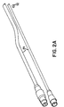
- FIG. 2A is a fragmentary perspective view of the electrical connector portion of the flow controller depicted in FIGS. 1 and 2 ;
- FIG. 3A is a cross-sectional view of a flow controller in accordance with an embodiment of the present invention, taken at section 3 A- 3 A of FIG. 1 ;
- FIG. 3B is an end elevation view of the flow controller of FIG. 3A ;
- FIG. 3C is a cross-sectional view of the flow controller of FIG. 3A taken at section 3 C- 3 C;
- FIG. 4 is a side elevation view of a flow controller in accordance with an embodiment of the present invention.
- FIG. 5A is an exploded view of a lead structure in accordance with an embodiment of the present invention.
- FIG. 5B is a plan view of the outer polymer layer of the lead structure of FIG. 5A ;
- FIG. 5C is a plan view of the copper layer of the lead structure of FIG. 5A ;
- FIG. 5D is a plan view of the trace layer of the lead structure of FIG. 5A ;
- FIG. 5E is a plan view of a second copper layer of the lead structure of FIG. 5A ;
- FIG. 5F is a plan view of the stiffener layer of the lead structure of FIG. 5A ;
- FIG. 5G is a plan view of the second outer polymer layer of the lead structure of FIG. 5A .
- the fluid control module 10 for delivering the desired quantity of fluid, which may be corrosive, in either a liquid or gaseous state.
- the fluid control module 10 generally includes a controller body 12 , a housing 14 , mounting plate 16 , pressure inlet/outlet fittings 18 , pressure transducers or sensors 20 , a control valve 22 , and integrated circuit or controller 60 .
- the controller body 12 and housing 14 are preferably manufactured from a chemically-inert, non-contaminating polymer such as polytetrafluoroethylene (PTFE), although other materials having similar chemically inert properties may also be used.
- the housing 14 and controller body 12 are mounted together by fasteners 24 extending through bores 26 .
- a gasket 28 of known suitable construction is preferably positioned between housing 14 and controller body 12 and providing an airtight seal. Controller body 12 and mounting plate 16 are also preferably secured together by fasteners 25 .
- General aspects of some of the described components and variations thereof are described in greater detail in U.S. Pat. No. 6,578,435, which is assigned to the same assignee as the present application, the entire disclosure of which is incorporated herein by reference.
- a flow passage 30 extends from the proximate end 13 of controller body 12 to proximate control valve inlet/outlet bore 32 .
- the flow passage 30 also extends from the distal end 15 of controller body 12 to the distal control valve inlet/outlet bore 34 .
- flow passage 30 does not extend through the entire controller body 12 in plane P from the proximate end 13 to the distal end 15 . Instead, a controller body plug 35 separates the flow passage 30 causing any fluid flow to be diverted through inlet/outlet bores 32 and 34 .
- control valve 22 When control valve 22 is inserted into its respective position, which will be discussed further below, the flow passage 30 and inlet/outlet bores 32 and 34 serve as the fluid flow passage within the fluid flow circuit. In an embodiment, the orientation of the fluid control module 10 , within the fluid flow circuit, may be reversed without affecting its effectiveness.
- cavities 36 , 38 , and 40 extend from the outer surface of the controller body 12 to the flow passage 30 .
- cavities 36 , 38 , and 40 may each extend into the controller body 12 from different sidewalls of the controller body 12 .
- Cavities 36 and 38 are separated a predetermined distance by dividing wall 37
- cavities 38 and 40 are separated a predetermined distance by dividing wall 39 .
- each pressure sensor 20 is held in place within their respective cavities by spacer ring 44 and externally threaded hold down ring 46 .
- the pressure sensors 20 are sealed within the controller body 12 by chemically inert o-ring seals 47 .
- a redundant seal may be created by the positioning of o-ring seal 48 .
- the seals 47 and 48 are readily available and of known construction to those of ordinary skill in the art.
- Insert 50 In flow passage 30 between the pressure sensors 20 , a constriction 51 is defined by insert 50 to create a pressure drop as the fluid flow traverses the chemically inert constriction 51 .
- Insert 50 may be formed from PTFE or other chemically inert polymer material, although other chemically inert materials are also contemplated such as sapphire, which is also resistant to wear when subjected to caustic fluids. Insert 50 may also be constructed of other materials that are compatible with the respective fluid flowing through conduit 30 and constriction 51 in fluid control module 10 . In certain embodiments, insert 50 is removable so that an eroded or clogged constriction 51 can be replaced or an insert 50 having a different size constricting area can be used.
- the cross-sectional area of flow passage 30 may be slightly larger in the area extending from end 13 to the area between the two pressure sensors 20 than the cross-sectional area of flow passage 30 extending from the area between the two pressure sensors 20 to controller body plug 35 .
- This difference in the cross-sectional area of the two portions of flow passage 30 may form a stop structure in the form of annular lip 52 , which prevents insert 50 from being inserted past the desired location in flow passage 30 .
- An insertable/removable insert 50 also enables the controller body 12 to be constructed of a single unitary piece.
- a rotatable manifold containing multiple constrictions 51 may be found in the area of dividing wall 37 .
- the constrictions 51 in the rotatable manifold may have the same or different constricting area size.
- a rotatable constriction manifold also enables the user to readily change the flow rate and/or replace the constriction after it becomes eroded or clogged.
- FIG. 3A illustrates a control valve 22 with a diaphragm 54 having a conical member 56 for opening and closing flow through conduit 30
- FIG. 3A illustrates a control valve 22 with a diaphragm 54 having a conical member 56 for opening and closing flow through conduit 30
- any various mechanisms for controlling flow through conduit 30 are readily available and of known construction to those of ordinary skill in the art.
- the actuation of the valve between the open and closed position may be accomplished with any of several mechanical, electrical, or pneumatic drivers of known suitable construction.
- the controller 60 may be in any of several forms including a dedicated solid-state device or a processor with associated control logic, and may include Read Only Memory (ROM) for storing programs to be executed by the processor and Random Access Memory (RAM) for storing operands used in carrying out the computations by the processor.
- ROM Read Only Memory
- RAM Random Access Memory
- the controller 60 is electrically coupled to a power supply and manipulates the electrical circuitry for sensing pressure and controlling the actuation of the control valve, wherein flow, pressure and/or volume may be controlled.
- the controller 60 is mounted to the interior top portion of the housing 14 .
- the controller 60 is used to convert the pressure readings from the two pressure sensors 20 to an analog or digital representation of flow or, alternatively, a pressure reading of the downstream pressure transducer.
- the raw analog signal from the upstream transducer is supplied to an input terminal and, likewise, the raw analog transducer output signal from the downstream transducer is supplied to an input terminal.
- the controller 60 computes the instantaneous pressure differences being picked up by the upstream and downstream transducers and performs any necessary zeroing adjustments and scaling.
- the controller 60 may also receive a signal corresponding to the temperature of the fluid flowing through flow passage 30 , which may be measured by a temperature sensor located in the pressure sensors 20 , diaphragm 54 of control valve 22 , or a separate temperature sensor, such as one sealed in a bore located in dividing wall 39 . Such measurements allow the potential for the measurement of temperature, pressure, and flow output in one fluid control module 10 . Additionally, such information provides the option of field selectable calibration for different fluid types and velocities.
- a lead structure 62 routes low voltage electrical magnetic interference (EMI) susceptible signals from each of the pressure sensors 20 to the controller 60 .
- the lead structure 62 is constructed of multiple layers forming a flexible Faraday cage. While providing the necessary shielding from electrical magnetic interference, the lead structure 62 also eliminates shielding material in the housing, enabling the flow control module 10 to be smaller, lighter, and more cost-effective.
- EMI electrical magnetic interference
- lead structure 62 generally includes an outer polymer layer 70 , a first shielding layer 72 , a trace layer including grounds on either ends 74 , a second shielding layer 76 , a stiffener layer 78 , and a second outer polymer layer 80 .
- the small end 120 of lead structure 62 defines apertures 122 which are received on, and electrically connect with, connection pins (not depicted) extending from controller 60 .
- each of connection pads 124 , 126 define apertures 128 , which are received on, and electrically connect with, connection pins (not depicted) extending from each of pressure sensors 20 .
- Lead structure 62 is preferably sufficiently flexible and resilient so as to enable it to be easily folded inside the housing. Generally, an overall thickness of 0.020 in flex areas is preferred.
- polymer layers 70 , 80 are polyimide.
- Shielding layers 72 , 76 generally include a thin layer of metallic material 130 , preferably copper, on an insulative polymer substrate 132 .
- Trace layer 74 generally includes a polymer substrate 133 with an outer strip 134 of metallic material circumscribing one or more signal conductors 136 .
- outer strip 134 is electrically conductively connected with the layer of metallic material 130 of each of shielding layers 72 , 76 , to surround signal conductors 136 with a Faraday cage.
- Stiffener layer 78 generally includes a layer of polymer material that may be slightly thicker and less resilient than the other layers to add strength and stiffness to the lead structure 62 .
- Outer polymer layers 70 , 80 may be applied to form the outer surfaces of lead structure 62 for protection and durability.
- housing 14 When controller body 12 and housing 14 are sealed, enclosing the control valve 22 , the pressure sensors 20 , controller 60 , and flexible circuit 62 , as depicted in FIGS. 3A and 4 , an interior area free from the harsh exterior environment is formed.
- housing 14 contains an aperture 82 that is sealed by aperture seal 85 , which allows electrical connectors 84 to pass through electrical connector apertures 86 .
- Electrical connector seals 88 insert into electrical connector apertures 86 and around electrical connectors 84 to maintain the sealed environment by keeping exterior fluid from entering.
- Aperture seal 85 may also contain a vent hole 90 into which a porous plastic vent plug 92 is inserted.
- vent plug 92 allows the passage of gases so that the internal area of housing 14 may be vented for true atmospheric pressure reference while restricting the flow of liquids into the internal area of the housing 14 .
- porous plastic materials are commercially available from Porex Corporation.
- Pressure transducers 20 also contain vent tubes 93 that open into the vented internal area of housing 14 for true atmospheric pressure reference.
- the pressure transducers 20 , control valve 22 , integrated circuit or controller 60 , and other necessary or desired electronics are potted with poured epoxy potting.
- such components may be insert molded into a single unitary chemically inert, non-contaminating material.
- the pressure sensors 20 may still be allowed to vent for true atmospheric pressure reference by having the vent tubes 93 extend to the exterior atmosphere. Vent plugs 90 may then be inserted into the ends of vent tubes 93 , allowing the passage of gases while restricting the flow of liquids into the pressure sensors 20 .
Abstract
Description
Claims (19)
Priority Applications (5)
| Application Number | Priority Date | Filing Date | Title |
|---|---|---|---|
| US11/482,542 US7866337B2 (en) | 2005-07-08 | 2006-07-07 | Chemically inert flow controller with non-contaminating body |
| KR1020087003186A KR101358607B1 (en) | 2005-07-08 | 2006-07-10 | Fluid handling device and flow controller |
| JP2008520415A JP5256032B2 (en) | 2005-07-08 | 2006-07-10 | Chemical inert flow control device with non-pollutants |
| EP06786652A EP1907735A4 (en) | 2005-07-08 | 2006-07-10 | Chemically inert flow controller with non-contaminating body |
| PCT/US2006/026570 WO2007008692A2 (en) | 2005-07-08 | 2006-07-10 | Chemically inert flow controller with non-contaminating body |
Applications Claiming Priority (2)
| Application Number | Priority Date | Filing Date | Title |
|---|---|---|---|
| US69748305P | 2005-07-08 | 2005-07-08 | |
| US11/482,542 US7866337B2 (en) | 2005-07-08 | 2006-07-07 | Chemically inert flow controller with non-contaminating body |
Publications (2)
| Publication Number | Publication Date |
|---|---|
| US20070089788A1 US20070089788A1 (en) | 2007-04-26 |
| US7866337B2 true US7866337B2 (en) | 2011-01-11 |
Family
ID=37637781
Family Applications (1)
| Application Number | Title | Priority Date | Filing Date |
|---|---|---|---|
| US11/482,542 Active 2026-10-09 US7866337B2 (en) | 2005-07-08 | 2006-07-07 | Chemically inert flow controller with non-contaminating body |
Country Status (5)
| Country | Link |
|---|---|
| US (1) | US7866337B2 (en) |
| EP (1) | EP1907735A4 (en) |
| JP (1) | JP5256032B2 (en) |
| KR (1) | KR101358607B1 (en) |
| WO (1) | WO2007008692A2 (en) |
Cited By (9)
| Publication number | Priority date | Publication date | Assignee | Title |
|---|---|---|---|---|
| US20100101664A1 (en) * | 2007-03-30 | 2010-04-29 | Asahi Organic Chemicals Industry Co., Ltd. | Fluid control apparatus |
| US20100193051A1 (en) * | 2009-02-05 | 2010-08-05 | Hiroki Igarashi | Differential-pressure flowmeter and flow-rate controller |
| US20130269795A1 (en) * | 2012-04-12 | 2013-10-17 | Horiba Stec, Co., Ltd. | Fluid controller |
| US8829926B2 (en) * | 2012-11-19 | 2014-09-09 | Zrro Technologies (2009) Ltd. | Transparent proximity sensor |
| US8991264B2 (en) | 2012-09-26 | 2015-03-31 | Rosemount Inc. | Integrally molded magnetic flowmeter |
| US9021890B2 (en) | 2012-09-26 | 2015-05-05 | Rosemount Inc. | Magnetic flowmeter with multiple coils |
| USD733587S1 (en) * | 2013-08-02 | 2015-07-07 | Ark Global Technology Ltd. | Flow control module |
| US20170097646A1 (en) * | 2015-10-02 | 2017-04-06 | Surpass Industry Co., Ltd. | Flow rate adjustment apparatus |
| US20210387127A1 (en) * | 2018-10-25 | 2021-12-16 | Donaldson Company, Inc. | Monitoring devices for air filtration systems |
Families Citing this family (13)
| Publication number | Priority date | Publication date | Assignee | Title |
|---|---|---|---|---|
| DE08103536T1 (en) | 2007-04-17 | 2009-04-16 | Kamstrup A/S | Consumption meter with embedded components |
| JP5408916B2 (en) * | 2008-07-08 | 2014-02-05 | サーパス工業株式会社 | Differential pressure flow meter and flow controller |
| US8048022B2 (en) * | 2009-01-30 | 2011-11-01 | Hospira, Inc. | Cassette for differential pressure based medication delivery flow sensor assembly for medication delivery monitoring and method of making the same |
| JP5209524B2 (en) * | 2009-02-05 | 2013-06-12 | サーパス工業株式会社 | Flow meter and flow controller |
| KR101737147B1 (en) | 2009-10-01 | 2017-05-17 | 가부시키가이샤 호리바 에스텍 | Flow rate measuring mechanism, mass flow controller, and pressure sensor |
| JP5501806B2 (en) * | 2010-03-05 | 2014-05-28 | サーパス工業株式会社 | Pressure sensor, differential pressure type flow meter and flow controller |
| EP2735782B1 (en) * | 2012-11-22 | 2018-07-18 | TI Automotive (Fuldabrück) GmbH | Quick coupling with integral sensor |
| WO2014158375A1 (en) * | 2013-03-12 | 2014-10-02 | Illinois Tool Works Inc. | Turning vane |
| US20150133861A1 (en) | 2013-11-11 | 2015-05-14 | Kevin P. McLennan | Thermal management system and method for medical devices |
| US10143795B2 (en) | 2014-08-18 | 2018-12-04 | Icu Medical, Inc. | Intravenous pole integrated power, control, and communication system and method for an infusion pump |
| AU2016267763B2 (en) | 2015-05-26 | 2021-07-08 | Icu Medical, Inc. | Disposable infusion fluid delivery device for programmable large volume drug delivery |
| US9785154B2 (en) * | 2017-02-13 | 2017-10-10 | Robert M. McMillan | Reconfigurable modular fluid flow control system for liquids or gases |
| USD939079S1 (en) | 2019-08-22 | 2021-12-21 | Icu Medical, Inc. | Infusion pump |
Citations (24)
| Publication number | Priority date | Publication date | Assignee | Title |
|---|---|---|---|---|
| USRE31570E (en) * | 1973-04-09 | 1984-05-01 | Tylan Corporation | Fluid flowmeter |
| US4687020A (en) * | 1985-05-17 | 1987-08-18 | Doyle James H | Fluid mass flow controller |
| US4858643A (en) * | 1988-03-14 | 1989-08-22 | Unit Instruments, Inc. | Fluid flow stabilizing apparatus |
| US4977916A (en) * | 1988-06-20 | 1990-12-18 | Stec Inc. | Mass flow controller |
| US5325728A (en) | 1993-06-22 | 1994-07-05 | Medtronic, Inc. | Electromagnetic flow meter |
| US5391874A (en) * | 1993-08-17 | 1995-02-21 | Galileo Electro-Optics Corporation | Flexible lead assembly for microchannel plate-based detector |
| US5571996A (en) * | 1995-01-17 | 1996-11-05 | Dell Usa, L.P. | Trace conductor layout configuration for preserving signal integrity in control boards requiring minimum connector stub separation |
| US5672832A (en) | 1996-02-15 | 1997-09-30 | Nt International, Inc. | Chemically inert flow meter within caustic fluids having non-contaminating body |
| US5693887A (en) | 1995-10-03 | 1997-12-02 | Nt International, Inc. | Pressure sensor module having non-contaminating body and isolation member |
| US5816285A (en) * | 1996-08-12 | 1998-10-06 | Fujikin Incorporated | Pressure type flow rate control apparatus |
| WO1999030388A1 (en) | 1997-12-05 | 1999-06-17 | Lk A/S | A method of reducing high frequency coupling between pairs of conductors in a connector, and a connector for transferring differential signals |
| US6062256A (en) * | 1997-02-11 | 2000-05-16 | Engineering Measurements Company | Micro mass flow control apparatus and method |
| US20030075349A1 (en) | 2001-10-19 | 2003-04-24 | Kruse John M. | Electrical interconnect between an articulating display and a pc based planar board |
| US6578435B2 (en) | 1999-11-23 | 2003-06-17 | Nt International, Inc. | Chemically inert flow control with non-contaminating body |
| US6597580B2 (en) * | 2001-11-30 | 2003-07-22 | Agilent Technologies, Inc. | Flexible shielded circuit board interface |
| US6612175B1 (en) | 2000-07-20 | 2003-09-02 | Nt International, Inc. | Sensor usable in ultra pure and highly corrosive environments |
| USRE38557E1 (en) | 1995-10-03 | 2004-07-20 | Nt International, Inc. | Non-contaminating pressure transducer module |
| WO2004083786A2 (en) | 2003-03-22 | 2004-09-30 | Siemens Aktiengesellschaft | Magnetic inductive flowmeter |
| US6813964B1 (en) | 2003-05-21 | 2004-11-09 | Hospira, Inc. | Fluid flow measurement device |
| US20050039947A1 (en) | 2001-01-17 | 2005-02-24 | Canon Kabushiki Kaisha | Multi-layered printed wiring board |
| US20050051215A1 (en) | 2003-09-04 | 2005-03-10 | Nugent Dale Alan | Apparatus for controlling and metering fluid flow |
| US6870794B2 (en) | 2000-07-13 | 2005-03-22 | Brunswick Corporation | Transducer and cable combination |
| WO2005050546A2 (en) | 2003-11-12 | 2005-06-02 | Tyco Electronics Corporation | Acoustic wave touch detecting apparatus |
| US7155983B2 (en) | 2005-02-04 | 2007-01-02 | Entegris, Inc. | Magnetic flow meter with unibody construction and conductive polymer electrodes |
Family Cites Families (6)
| Publication number | Priority date | Publication date | Assignee | Title |
|---|---|---|---|---|
| JP3335688B2 (en) * | 1992-12-01 | 2002-10-21 | 株式会社技術開発総合研究所 | Flowmeter |
| JP2904135B2 (en) * | 1996-06-25 | 1999-06-14 | 富士ゼロックス株式会社 | Printed wiring board |
| JP3926465B2 (en) * | 1998-03-09 | 2007-06-06 | アドバンスド エナジー ジャパン株式会社 | Mass flow controller shunt structure |
| JP2000269632A (en) * | 1999-03-17 | 2000-09-29 | Tatsuta Electric Wire & Cable Co Ltd | Shield flexible printed wiring board, manufacture thereof and reinforcing shield film therefor |
| JP2002151807A (en) * | 2000-11-08 | 2002-05-24 | Saginomiya Seisakusho Inc | Wiring board and pressure sensor |
| JP2003099908A (en) * | 2001-09-25 | 2003-04-04 | Sony Corp | Rotating magnetic head assembly |
-
2006
- 2006-07-07 US US11/482,542 patent/US7866337B2/en active Active
- 2006-07-10 JP JP2008520415A patent/JP5256032B2/en active Active
- 2006-07-10 KR KR1020087003186A patent/KR101358607B1/en active IP Right Grant
- 2006-07-10 EP EP06786652A patent/EP1907735A4/en not_active Withdrawn
- 2006-07-10 WO PCT/US2006/026570 patent/WO2007008692A2/en active Application Filing
Patent Citations (26)
| Publication number | Priority date | Publication date | Assignee | Title |
|---|---|---|---|---|
| USRE31570E (en) * | 1973-04-09 | 1984-05-01 | Tylan Corporation | Fluid flowmeter |
| US4687020A (en) * | 1985-05-17 | 1987-08-18 | Doyle James H | Fluid mass flow controller |
| US4858643A (en) * | 1988-03-14 | 1989-08-22 | Unit Instruments, Inc. | Fluid flow stabilizing apparatus |
| US4977916A (en) * | 1988-06-20 | 1990-12-18 | Stec Inc. | Mass flow controller |
| US5325728A (en) | 1993-06-22 | 1994-07-05 | Medtronic, Inc. | Electromagnetic flow meter |
| US5391874A (en) * | 1993-08-17 | 1995-02-21 | Galileo Electro-Optics Corporation | Flexible lead assembly for microchannel plate-based detector |
| US5571996A (en) * | 1995-01-17 | 1996-11-05 | Dell Usa, L.P. | Trace conductor layout configuration for preserving signal integrity in control boards requiring minimum connector stub separation |
| US5693887A (en) | 1995-10-03 | 1997-12-02 | Nt International, Inc. | Pressure sensor module having non-contaminating body and isolation member |
| USRE38557E1 (en) | 1995-10-03 | 2004-07-20 | Nt International, Inc. | Non-contaminating pressure transducer module |
| US5672832A (en) | 1996-02-15 | 1997-09-30 | Nt International, Inc. | Chemically inert flow meter within caustic fluids having non-contaminating body |
| US5816285A (en) * | 1996-08-12 | 1998-10-06 | Fujikin Incorporated | Pressure type flow rate control apparatus |
| US6062256A (en) * | 1997-02-11 | 2000-05-16 | Engineering Measurements Company | Micro mass flow control apparatus and method |
| WO1999030388A1 (en) | 1997-12-05 | 1999-06-17 | Lk A/S | A method of reducing high frequency coupling between pairs of conductors in a connector, and a connector for transferring differential signals |
| US6578435B2 (en) | 1999-11-23 | 2003-06-17 | Nt International, Inc. | Chemically inert flow control with non-contaminating body |
| US6870794B2 (en) | 2000-07-13 | 2005-03-22 | Brunswick Corporation | Transducer and cable combination |
| US6612175B1 (en) | 2000-07-20 | 2003-09-02 | Nt International, Inc. | Sensor usable in ultra pure and highly corrosive environments |
| US20050039947A1 (en) | 2001-01-17 | 2005-02-24 | Canon Kabushiki Kaisha | Multi-layered printed wiring board |
| US20030075349A1 (en) | 2001-10-19 | 2003-04-24 | Kruse John M. | Electrical interconnect between an articulating display and a pc based planar board |
| US6597580B2 (en) * | 2001-11-30 | 2003-07-22 | Agilent Technologies, Inc. | Flexible shielded circuit board interface |
| WO2004083786A2 (en) | 2003-03-22 | 2004-09-30 | Siemens Aktiengesellschaft | Magnetic inductive flowmeter |
| US20070163359A1 (en) | 2003-03-22 | 2007-07-19 | Soren Nielsen | Magnetic inductive flowmeter |
| US7415894B2 (en) | 2003-03-22 | 2008-08-26 | Siemens Aktiengesellschaft | Magnetic inductive flowmeter having a plug-type electrode connection |
| US6813964B1 (en) | 2003-05-21 | 2004-11-09 | Hospira, Inc. | Fluid flow measurement device |
| US20050051215A1 (en) | 2003-09-04 | 2005-03-10 | Nugent Dale Alan | Apparatus for controlling and metering fluid flow |
| WO2005050546A2 (en) | 2003-11-12 | 2005-06-02 | Tyco Electronics Corporation | Acoustic wave touch detecting apparatus |
| US7155983B2 (en) | 2005-02-04 | 2007-01-02 | Entegris, Inc. | Magnetic flow meter with unibody construction and conductive polymer electrodes |
Non-Patent Citations (1)
| Title |
|---|
| Supplementary European Search Report for Application No. EP 06 78 6652, dated Aug. 28, 2008. |
Cited By (13)
| Publication number | Priority date | Publication date | Assignee | Title |
|---|---|---|---|---|
| US20100101664A1 (en) * | 2007-03-30 | 2010-04-29 | Asahi Organic Chemicals Industry Co., Ltd. | Fluid control apparatus |
| US20100193051A1 (en) * | 2009-02-05 | 2010-08-05 | Hiroki Igarashi | Differential-pressure flowmeter and flow-rate controller |
| US8225814B2 (en) * | 2009-02-05 | 2012-07-24 | Surpass Industry Co., Ltd. | Differential-pressure flowmeter and flow-rate controller |
| US8910656B2 (en) * | 2012-04-12 | 2014-12-16 | Horiba Stec, Co., Ltd. | Fluid controller |
| US20130269795A1 (en) * | 2012-04-12 | 2013-10-17 | Horiba Stec, Co., Ltd. | Fluid controller |
| US8991264B2 (en) | 2012-09-26 | 2015-03-31 | Rosemount Inc. | Integrally molded magnetic flowmeter |
| US9021890B2 (en) | 2012-09-26 | 2015-05-05 | Rosemount Inc. | Magnetic flowmeter with multiple coils |
| US8829926B2 (en) * | 2012-11-19 | 2014-09-09 | Zrro Technologies (2009) Ltd. | Transparent proximity sensor |
| USD733587S1 (en) * | 2013-08-02 | 2015-07-07 | Ark Global Technology Ltd. | Flow control module |
| US20170097646A1 (en) * | 2015-10-02 | 2017-04-06 | Surpass Industry Co., Ltd. | Flow rate adjustment apparatus |
| US9977436B2 (en) * | 2015-10-02 | 2018-05-22 | Surpass Industry Co., Ltd. | Flow rate adjustment apparatus |
| US20210387127A1 (en) * | 2018-10-25 | 2021-12-16 | Donaldson Company, Inc. | Monitoring devices for air filtration systems |
| US11925890B2 (en) * | 2018-10-25 | 2024-03-12 | Donaldson Company, Inc. | Monitoring devices for air filtration systems |
Also Published As
| Publication number | Publication date |
|---|---|
| KR101358607B1 (en) | 2014-02-04 |
| US20070089788A1 (en) | 2007-04-26 |
| JP2009500629A (en) | 2009-01-08 |
| EP1907735A4 (en) | 2008-10-08 |
| JP5256032B2 (en) | 2013-08-07 |
| WO2007008692B1 (en) | 2007-07-19 |
| WO2007008692A3 (en) | 2007-05-10 |
| WO2007008692A2 (en) | 2007-01-18 |
| EP1907735A2 (en) | 2008-04-09 |
| KR20080041644A (en) | 2008-05-13 |
Similar Documents
| Publication | Publication Date | Title |
|---|---|---|
| US7866337B2 (en) | Chemically inert flow controller with non-contaminating body | |
| US5672832A (en) | Chemically inert flow meter within caustic fluids having non-contaminating body | |
| US6578435B2 (en) | Chemically inert flow control with non-contaminating body | |
| EP0853758B1 (en) | Pressure sensor module having non-contaminating body | |
| US5869766A (en) | Non-contaminating pressure transducer module | |
| WO1997030333A8 (en) | Flow meter within caustic fluids having non-contaminating body | |
| US7921726B2 (en) | Fluid sensor with mechanical positional feedback | |
| JP5208949B2 (en) | Process pressure measuring system with outlet | |
| TWI421660B (en) | Chemically inert flow controller with non-contaminating body | |
| US11104147B2 (en) | Flow channel pressure measurement | |
| KR102438237B1 (en) | Liquid source supply system and liquid source supply method using the same | |
| WO1999028718A1 (en) | Fluid monitoring device | |
| CN116104963A (en) | System and apparatus for a valve assembly |
Legal Events
| Date | Code | Title | Description |
|---|---|---|---|
| AS | Assignment |
Owner name: ENTEGRIS, INC., MINNESOTA Free format text: ASSIGNMENT OF ASSIGNORS INTEREST;ASSIGNORS:CHINNOCK, ROBERT T.;MILLER, CLIFFORD;MEACHAM, CHARLES;SIGNING DATES FROM 20061026 TO 20061205;REEL/FRAME:018701/0289 Owner name: ENTEGRIS, INC., MINNESOTA Free format text: ASSIGNMENT OF ASSIGNORS INTEREST;ASSIGNORS:CHINNOCK, ROBERT T.;MILLER, CLIFFORD;MEACHAM, CHARLES;REEL/FRAME:018701/0289;SIGNING DATES FROM 20061026 TO 20061205 |
|
| AS | Assignment |
Owner name: WELLS FARGO BANK, NATIONAL ASSOCIATION, AS AGENT, Free format text: SECURITY AGREEMENT;ASSIGNOR:ENTEGRIS, INC.;REEL/FRAME:022354/0784 Effective date: 20090302 Owner name: WELLS FARGO BANK, NATIONAL ASSOCIATION, AS AGENT,M Free format text: SECURITY AGREEMENT;ASSIGNOR:ENTEGRIS, INC.;REEL/FRAME:022354/0784 Effective date: 20090302 |
|
| STCF | Information on status: patent grant |
Free format text: PATENTED CASE |
|
| AS | Assignment |
Owner name: ENTEGRIS, INC., MASSACHUSETTS Free format text: RELEASE BY SECURED PARTY;ASSIGNOR:WELLS FARGO BANK NATIONAL ASSOCIATION;REEL/FRAME:026764/0880 Effective date: 20110609 |
|
| AS | Assignment |
Owner name: GOLDMAN SACHS BANK USA, AS COLLATERAL AGENT, NEW YORK Free format text: SECURITY INTEREST;ASSIGNORS:ENTEGRIS, INC.;POCO GRAPHITE, INC.;ATMI, INC.;AND OTHERS;REEL/FRAME:032815/0852 Effective date: 20140430 Owner name: GOLDMAN SACHS BANK USA, AS COLLATERAL AGENT, NEW Y Free format text: SECURITY INTEREST;ASSIGNORS:ENTEGRIS, INC.;POCO GRAPHITE, INC.;ATMI, INC.;AND OTHERS;REEL/FRAME:032815/0852 Effective date: 20140430 |
|
| AS | Assignment |
Owner name: GOLDMAN SACHS BANK USA, AS COLLATERAL AGENT, NEW YORK Free format text: SECURITY INTEREST;ASSIGNORS:ENTEGRIS, INC.;POCO GRAPHITE, INC.;ATMI, INC.;AND OTHERS;REEL/FRAME:032812/0192 Effective date: 20140430 Owner name: GOLDMAN SACHS BANK USA, AS COLLATERAL AGENT, NEW Y Free format text: SECURITY INTEREST;ASSIGNORS:ENTEGRIS, INC.;POCO GRAPHITE, INC.;ATMI, INC.;AND OTHERS;REEL/FRAME:032812/0192 Effective date: 20140430 |
|
| FPAY | Fee payment |
Year of fee payment: 4 |
|
| MAFP | Maintenance fee payment |
Free format text: PAYMENT OF MAINTENANCE FEE, 8TH YEAR, LARGE ENTITY (ORIGINAL EVENT CODE: M1552) Year of fee payment: 8 |
|
| AS | Assignment |
Owner name: ADVANCED TECHNOLOGY MATERIALS, INC., CONNECTICUT Free format text: RELEASE BY SECURED PARTY;ASSIGNOR:GOLDMAN SACHS BANK USA, AS COLLATERAL AGENT;REEL/FRAME:047477/0032 Effective date: 20181106 Owner name: ENTEGRIS, INC., MASSACHUSETTS Free format text: RELEASE BY SECURED PARTY;ASSIGNOR:GOLDMAN SACHS BANK USA, AS COLLATERAL AGENT;REEL/FRAME:047477/0032 Effective date: 20181106 Owner name: POCO GRAPHITE, INC., MASSACHUSETTS Free format text: RELEASE BY SECURED PARTY;ASSIGNOR:GOLDMAN SACHS BANK USA, AS COLLATERAL AGENT;REEL/FRAME:047477/0032 Effective date: 20181106 Owner name: ATMI PACKAGING, INC., CONNECTICUT Free format text: RELEASE BY SECURED PARTY;ASSIGNOR:GOLDMAN SACHS BANK USA, AS COLLATERAL AGENT;REEL/FRAME:047477/0032 Effective date: 20181106 Owner name: ATMI, INC., CONNECTICUT Free format text: RELEASE BY SECURED PARTY;ASSIGNOR:GOLDMAN SACHS BANK USA, AS COLLATERAL AGENT;REEL/FRAME:047477/0032 Effective date: 20181106 Owner name: ENTEGRIS, INC., MASSACHUSETTS Free format text: RELEASE BY SECURED PARTY;ASSIGNOR:GOLDMAN SACHS BANK USA, AS COLLATERAL AGENT;REEL/FRAME:047477/0151 Effective date: 20181106 Owner name: ATMI, INC., CONNECTICUT Free format text: RELEASE BY SECURED PARTY;ASSIGNOR:GOLDMAN SACHS BANK USA, AS COLLATERAL AGENT;REEL/FRAME:047477/0151 Effective date: 20181106 Owner name: ADVANCED TECHNOLOGY MATERIALS, INC., CONNECTICUT Free format text: RELEASE BY SECURED PARTY;ASSIGNOR:GOLDMAN SACHS BANK USA, AS COLLATERAL AGENT;REEL/FRAME:047477/0151 Effective date: 20181106 Owner name: POCO GRAPHITE, INC., MASSACHUSETTS Free format text: RELEASE BY SECURED PARTY;ASSIGNOR:GOLDMAN SACHS BANK USA, AS COLLATERAL AGENT;REEL/FRAME:047477/0151 Effective date: 20181106 Owner name: ATMI PACKAGING, INC., CONNECTICUT Free format text: RELEASE BY SECURED PARTY;ASSIGNOR:GOLDMAN SACHS BANK USA, AS COLLATERAL AGENT;REEL/FRAME:047477/0151 Effective date: 20181106 |
|
| AS | Assignment |
Owner name: GOLDMAN SACHS BANK USA, NEW YORK Free format text: SECURITY INTEREST;ASSIGNORS:ENTEGRIS, INC.;SAES PURE GAS, INC.;REEL/FRAME:048811/0679 Effective date: 20181106 |
|
| AS | Assignment |
Owner name: MORGAN STANLEY SENIOR FUNDING, INC., MARYLAND Free format text: ASSIGNMENT OF PATENT SECURITY INTEREST RECORDED AT REEL/FRAME 048811/0679;ASSIGNOR:GOLDMAN SACHS BANK USA;REEL/FRAME:050965/0035 Effective date: 20191031 |
|
| MAFP | Maintenance fee payment |
Free format text: PAYMENT OF MAINTENANCE FEE, 12TH YEAR, LARGE ENTITY (ORIGINAL EVENT CODE: M1553); ENTITY STATUS OF PATENT OWNER: LARGE ENTITY Year of fee payment: 12 |
|
| AS | Assignment |
Owner name: TRUIST BANK, AS NOTES COLLATERAL AGENT, NORTH CAROLINA Free format text: SECURITY INTEREST;ASSIGNORS:ENTEGRIS, INC.;ENTEGRIS GP, INC.;POCO GRAPHITE, INC.;AND OTHERS;REEL/FRAME:060613/0072 Effective date: 20220706 |