US7857752B2 - Medical image processing apparatus and medical image processing method - Google Patents
Medical image processing apparatus and medical image processing method Download PDFInfo
- Publication number
- US7857752B2 US7857752B2 US11/821,898 US82189807A US7857752B2 US 7857752 B2 US7857752 B2 US 7857752B2 US 82189807 A US82189807 A US 82189807A US 7857752 B2 US7857752 B2 US 7857752B2
- Authority
- US
- United States
- Prior art keywords
- image
- section
- junction
- picked
- medical image
- Prior art date
- Legal status (The legal status is an assumption and is not a legal conclusion. Google has not performed a legal analysis and makes no representation as to the accuracy of the status listed.)
- Active, expires
Links
- 238000012545 processing Methods 0.000 title claims abstract description 164
- 238000003672 processing method Methods 0.000 title claims description 12
- 210000000981 epithelium Anatomy 0.000 claims abstract description 66
- 238000006243 chemical reaction Methods 0.000 claims abstract description 48
- 238000004458 analytical method Methods 0.000 claims abstract description 34
- 238000011156 evaluation Methods 0.000 claims abstract description 16
- 238000001727 in vivo Methods 0.000 claims abstract description 14
- 208000023514 Barrett esophagus Diseases 0.000 claims description 76
- 208000023665 Barrett oesophagus Diseases 0.000 claims description 76
- 210000003238 esophagus Anatomy 0.000 claims description 62
- 239000013598 vector Substances 0.000 claims description 51
- 210000002784 stomach Anatomy 0.000 claims description 18
- 238000003780 insertion Methods 0.000 claims description 15
- 230000037431 insertion Effects 0.000 claims description 15
- 238000005286 illumination Methods 0.000 claims description 10
- 230000004075 alteration Effects 0.000 claims description 9
- 230000005484 gravity Effects 0.000 claims description 3
- 238000011161 development Methods 0.000 claims 1
- 238000010586 diagram Methods 0.000 description 50
- 230000000875 corresponding effect Effects 0.000 description 35
- 210000003236 esophagogastric junction Anatomy 0.000 description 26
- 210000004877 mucosa Anatomy 0.000 description 19
- 210000000056 organ Anatomy 0.000 description 18
- 238000000034 method Methods 0.000 description 17
- TXXHDPDFNKHHGW-CCAGOZQPSA-N cis,cis-muconic acid Chemical compound OC(=O)\C=C/C=C\C(O)=O TXXHDPDFNKHHGW-CCAGOZQPSA-N 0.000 description 16
- 238000003745 diagnosis Methods 0.000 description 8
- 238000012937 correction Methods 0.000 description 7
- 239000011159 matrix material Substances 0.000 description 7
- 230000008901 benefit Effects 0.000 description 5
- 238000011144 upstream manufacturing Methods 0.000 description 5
- RNAMYOYQYRYFQY-UHFFFAOYSA-N 2-(4,4-difluoropiperidin-1-yl)-6-methoxy-n-(1-propan-2-ylpiperidin-4-yl)-7-(3-pyrrolidin-1-ylpropoxy)quinazolin-4-amine Chemical compound N1=C(N2CCC(F)(F)CC2)N=C2C=C(OCCCN3CCCC3)C(OC)=CC2=C1NC1CCN(C(C)C)CC1 RNAMYOYQYRYFQY-UHFFFAOYSA-N 0.000 description 4
- 230000008859 change Effects 0.000 description 4
- 238000001514 detection method Methods 0.000 description 4
- 230000003287 optical effect Effects 0.000 description 4
- 201000010099 disease Diseases 0.000 description 3
- 208000037265 diseases, disorders, signs and symptoms Diseases 0.000 description 3
- 230000000694 effects Effects 0.000 description 3
- 230000003902 lesion Effects 0.000 description 3
- 230000008569 process Effects 0.000 description 3
- 238000012935 Averaging Methods 0.000 description 2
- 210000002318 cardia Anatomy 0.000 description 2
- 230000002596 correlated effect Effects 0.000 description 2
- 238000003708 edge detection Methods 0.000 description 2
- 210000001156 gastric mucosa Anatomy 0.000 description 2
- 210000001035 gastrointestinal tract Anatomy 0.000 description 2
- 210000000214 mouth Anatomy 0.000 description 2
- NCGICGYLBXGBGN-UHFFFAOYSA-N 3-morpholin-4-yl-1-oxa-3-azonia-2-azanidacyclopent-3-en-5-imine;hydrochloride Chemical compound Cl.[N-]1OC(=N)C=[N+]1N1CCOCC1 NCGICGYLBXGBGN-UHFFFAOYSA-N 0.000 description 1
- 238000012327 Endoscopic diagnosis Methods 0.000 description 1
- 239000002253 acid Substances 0.000 description 1
- 150000007513 acids Chemical class 0.000 description 1
- 210000004204 blood vessel Anatomy 0.000 description 1
- 239000002775 capsule Substances 0.000 description 1
- 230000001747 exhibiting effect Effects 0.000 description 1
- 238000000605 extraction Methods 0.000 description 1
- 210000000887 face Anatomy 0.000 description 1
- 238000001914 filtration Methods 0.000 description 1
- 210000000936 intestine Anatomy 0.000 description 1
- 210000002429 large intestine Anatomy 0.000 description 1
- 238000012986 modification Methods 0.000 description 1
- 230000004048 modification Effects 0.000 description 1
- 230000001151 other effect Effects 0.000 description 1
- 238000007781 pre-processing Methods 0.000 description 1
- 230000003252 repetitive effect Effects 0.000 description 1
- 230000004044 response Effects 0.000 description 1
- 238000005070 sampling Methods 0.000 description 1
- 208000024891 symptom Diseases 0.000 description 1
Images


Classifications
-
- G06T5/80—
-
- A—HUMAN NECESSITIES
- A61—MEDICAL OR VETERINARY SCIENCE; HYGIENE
- A61B—DIAGNOSIS; SURGERY; IDENTIFICATION
- A61B1/00—Instruments for performing medical examinations of the interior of cavities or tubes of the body by visual or photographical inspection, e.g. endoscopes; Illuminating arrangements therefor
- A61B1/00002—Operational features of endoscopes
- A61B1/00043—Operational features of endoscopes provided with output arrangements
- A61B1/00045—Display arrangement
- A61B1/0005—Display arrangement combining images e.g. side-by-side, superimposed or tiled
-
- G—PHYSICS
- G06—COMPUTING; CALCULATING OR COUNTING
- G06T—IMAGE DATA PROCESSING OR GENERATION, IN GENERAL
- G06T3/00—Geometric image transformation in the plane of the image
-
- A—HUMAN NECESSITIES
- A61—MEDICAL OR VETERINARY SCIENCE; HYGIENE
- A61B—DIAGNOSIS; SURGERY; IDENTIFICATION
- A61B1/00—Instruments for performing medical examinations of the interior of cavities or tubes of the body by visual or photographical inspection, e.g. endoscopes; Illuminating arrangements therefor
- A61B1/04—Instruments for performing medical examinations of the interior of cavities or tubes of the body by visual or photographical inspection, e.g. endoscopes; Illuminating arrangements therefor combined with photographic or television appliances
- A61B1/042—Instruments for performing medical examinations of the interior of cavities or tubes of the body by visual or photographical inspection, e.g. endoscopes; Illuminating arrangements therefor combined with photographic or television appliances characterised by a proximal camera, e.g. a CCD camera
Definitions
- the present invention relates to a medical image processing apparatus and medical image processing method for performing image processing including creating an image of a developed view of a medical image such as an endoscopic image.
- the esophagus is covered by the mucosa of the squamous epithelium, and the stomach and the intestine are covered by the mucosa of the columnar epithelium.
- Barrett's esophagus is considered that the mucosa of the esophagus (the squamous epithelium) near the junction between the stomach and the esophagus is denatured to a columnar epithelium continuously from the stomach due to the backflow of stomach acids to the esophagus.
- an endoscopic diagnosis may be applied that uses an endoscope to observe how the columnar epithelium present continuously from the esophagogastric junction extends and a distinctive form of the junction between the columnar epithelium and the squamous epithelium.
- Japanese Unexamined Patent Application Publication No. 8-256295 discloses means for correcting an optical distortion occurring in the periphery of a captured endoscopic image.
- a medical image processing apparatus including:
- an image conversion section that geometrically converts a medical image resulting from the image pickup of a tubular part in vivo
- a developed-view output section that outputs a converted image obtained by the image conversion section to a display device as an image of a developed view.
- a medical image processing method including:
- FIG. 1 is a block diagram showing a configuration of an endoscopic system including Embodiment 1 of the present invention.
- FIG. 2 is a diagram showing a state in which an image is picked up by an endoscope inserted through a tubular organ such as the esophagus.
- FIG. 3 is a diagram showing an endoscopic image picked up by an image pickup apparatus provided in the endoscope in FIG. 2 .
- FIG. 4 is a block diagram showing an image processing function by a CPU.
- FIG. 5 is a flowchart showing processing steps for creating a developed view.
- FIG. 6 is a diagram showing a relationship between an endoscopic image and a developed view.
- FIG. 7 is an explanatory diagram on a positional relationship between a coordinate position, which is obtained from a developed view, and pixels of an endoscopic image.
- FIG. 8 is a diagram showing a state that a created developed view and an endoscopic image are displayed on a monitor.
- FIG. 9 is an explanatory diagram showing a state that an endoscopic image in Embodiment 2 of the present invention is projected to the surface of a cylinder.
- FIG. 10 is a flowchart showing processing steps for creating a developed view in Embodiment 2.
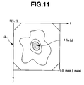
- FIG. 11 is an explanatory diagram showing pixel positions on an endoscope image.
- FIG. 12 is an explanatory diagram for creating a developed view by projecting positions of pixels on an endoscopic image to the surface of a cylinder and pasting the intensity values of the pixels thereto.
- FIG. 13 is an explanatory diagram for performing interpolation processing if the positions to which the pixels of an endoscopic image are pasted do not agree with the positions of the image displayed as a developed view on a display device.
- FIG. 14 is an explanatory diagram showing a state that an endoscopic image in Embodiment 3 of the present invention is projected to the surface of a cylinder.
- FIG. 15 is an explanatory diagram showing a state that light from a light source is reflected by the surface of an object.
- FIG. 16A is a diagram showing a positional relationship in which an image pickup apparatus of an endoscope exists on the center axis of a cylinder and a model image corresponding thereto.
- FIG. 16B is a diagram showing a positional relationship resulting from the parallel movement of the image pickup apparatus upward from the state in FIG. 16A and a model image corresponding thereto.
- FIG. 16C is a diagram showing a positional relationship resulting from the tilting of the axis direction of the insertion section from the state in FIG. 16A and a model image corresponding thereto.
- FIG. 17 is a flowchart showing processing steps for creating a developed view in Embodiment 3.
- FIG. 18 is a configuration diagram of a capsule-type endoscopic system including a variation example.
- FIG. 19 is a block diagram showing a configuration of an endoscopic system including Embodiment 4 of the present invention.
- FIG. 20 is a block diagram showing an image processing function by a CPU.
- FIG. 21 is a flowchart showing processing steps for creating a developed view.
- FIG. 22 is a diagram showing a positional relationship between corresponding points on an object, which correspond to pixels of a picked up image and a light source, for example.
- FIG. 23A is a diagram showing a state that light from a light source is reflected by the surface of an object.
- FIG. 23B is a diagram specifically showing the state in FIG. 23A .
- FIG. 24 is a diagram showing multiple normal vectors defined around corresponding points.
- FIG. 25 is a diagram showing that a vector m passes through a position on an image.
- FIG. 26 is an explanatory diagram for calculating the straight line passing through the center of a three-dimensional form.
- FIG. 27 is an explanatory diagram of conversion from a coordinate system of a three dimensional form to a coordinate system based on a straight line.
- FIG. 28A is a diagram showing an endoscopic image obtained by a direct-view type endoscope.
- FIG. 28B is an explanatory diagram showing a relationship between an endoscopic image and the surface of a cylinder modeling the esophagus.
- FIG. 28C is a diagram showing a developed view created from the endoscopic image projected on the surface of the cylinder in FIG. 28B .
- FIG. 29 is an explanatory diagram for creating a developed view by interpolation processing.
- FIG. 30 is a diagram showing an endoscopic image and developed view, which are developed on a display device.
- FIG. 31 is a flowchart showing a part of processing steps for creating a developed view in Embodiment 5 of the present invention.
- FIG. 32 is an explanatory diagram of processing details in FIG. 31 .
- FIG. 33 is an explanatory diagram of a state that an amount of shift between a template image and a reference image is calculated.
- FIG. 34 is a block diagram showing a configuration of an endoscopic system including Embodiment 6 of the present invention.
- FIG. 35 is a diagram showing an endoscopic image picked up by an image pickup apparatus of the endoscope in FIG. 34 .
- FIG. 36 is a diagram showing an image processing function by a CPU.
- FIG. 37 is a flowchart showing processing steps for determining whether Barrett's esophagus through processing of creating a developed view or not.
- FIG. 38 is a diagram showing a relationship between an endoscopic image and a created developed view.
- FIG. 39 is a flowchart of processing steps of creating a developed view from an endoscopic image.
- FIG. 40 is a flowchart of processing steps of detecting the squamocolumnar junction in FIG. 37 .
- FIG. 41 is a diagram showing a developed view displaying the calculated average values in Z direction of the squamocolumnar junction.
- FIG. 42 is a diagram showing a histogram example in which a reference value, which functions as a criterion, is calculated from a histogram of distributed values of samples in a case of the squamocolumnar junction which has been already diagnosed and a case of Barrett's esophagus.
- FIG. 43 is a diagram showing a display example on a monitor displaying an endoscopic image, a developed view and a determination result.
- FIG. 44A is a diagram showing an endoscopic image obtained by a direct-view type endoscope.
- FIG. 44B is an explanatory diagram showing a relationship between the endoscopic image in FIG. 44A and the surface of a cylinder modeling the esophagus.
- FIG. 44C is a diagram showing a developed view created from an endoscopic image projected on the surface of the cylinder in FIG. 44B .
- FIG. 45 is a diagram showing an endoscopic image and a developed view in Embodiment 7 of the present invention.
- FIG. 46 is a flowchart showing processing steps for determining whether Barrett's esophagus through processing of creating a developed view or not.
- FIG. 47 is a diagram showing an endoscopic image and a developed view in Embodiment 8 of the present invention.
- FIG. 48 is a flowchart showing processing steps for determining whether Barrett's esophagus through processing of creating a developed view or not.
- FIG. 49 is an explanatory diagram for a case that the distance between two adjacent points at the squamocolumnar junction in a developed view in Embodiment 9 is calculated.
- FIG. 50 is a flowchart showing processing steps for determining whether Barrett's esophagus by calculating the total sum of the distances between adjacent two points at the squamocolumnar junction or not.
- FIG. 51A is an explanatory diagram showing a state that vectors are defined at the squamocolumnar junction in the developed view created from an endoscopic image in Embodiment 10.
- FIG. 51B is an explanatory diagram showing a state that the angle formed by adjacent two vectors is calculated from adjacent three points at the squamocolumnar junction of a developed view.
- FIG. 52 is a flowchart showing processing steps for determining whether Barrett's esophagus by calculating the total sum of angles made by adjacent two vectors or not.
- FIG. 53 is an explanatory diagram showing a state that the gradient of the vector connecting adjacent two points at the squamocolumnar junction in a developed view in Embodiment 11 is calculated.
- FIG. 54 is a flowchart showing processing steps for calculating the total number of inflection points where the gradient of a vector changes from positive to negative or from negative to positive and from the total number, determining whether Barrett's esophagus or not.
- Embodiment 1 of the present invention will be described.
- An endoscopic system 1 shown in FIG. 1 includes an endoscopic observation apparatus 2 , an endoscopic image processor (which will be simply abbreviated to image processor) 3 including a personal computer that performs image processing on an endoscopic image obtained by the endoscopic observation apparatus 2 and being Embodiment 1 of the medical image processing apparatus of the present invention, and a display monitor 4 displaying an image image-processed by the image processor 3 .
- an endoscopic image processor which will be simply abbreviated to image processor
- image processor 3 including a personal computer that performs image processing on an endoscopic image obtained by the endoscopic observation apparatus 2 and being Embodiment 1 of the medical image processing apparatus of the present invention
- a display monitor 4 displaying an image image-processed by the image processor 3 .
- the endoscopic observation apparatus 2 has an endoscope 6 to be inserted to a body cavity, a light source device 7 supplying illumination light to the endoscope 6 , a camera control unit (which will be abbreviated to CCU) 8 performing signal processing for image pickup means of the endoscope 6 , and a monitor 9 displaying an endoscopic image shot by an image pickup device by receiving the input of video signals outputted from the CCU 8 .
- the endoscope 6 has a long and narrow insertion section 11 to be inserted to a body cavity and an operating section 12 provided at the rear end of the insertion section 11 .
- a light guide 13 transmitting illumination light is contained through the insertion section 11 .
- the rear end of the light guide 13 is connected to the light source device 7 . Illumination light supplied from the light source device 7 is transferred by the light guide 13 and (the transmitted illumination light) is outputted from the distal end surface mounted on an illumination window provided at a distal end 14 of the insertion section 11 and illuminates a subject such as an affected part.
- An image pickup apparatus 17 which includes an objective 15 mounted on an observation window adjacent to the illumination window and a charge-coupled device (which will be abbreviated to CCD) 16 , for example, functioning as a solid-state image pickup device placed at the image-forming position of the objective 15 . Then, the optical image formed on the image pickup plane of the CCD 16 is photoelectronically converted by the CCD 16 .
- CCD charge-coupled device
- the CCD 16 is connected to the CCU 8 through a signal line, and, in response to the application of a CCD driving signal from the CCU 8 , the CCD 16 outputs the photoelectronically-converted image signals.
- the image signals are signal-processed by a video processing circuit within the CCU 8 and are converted to video signals.
- the video signals are outputted to the monitor 9 , and an endoscopic image is displayed on the display plane of the monitor 9 .
- the video signals are also inputted to the image processor 3 .
- the image processor 3 has an image input section 21 , a CPU 22 and a processing program storage section 23 .
- the image input section 21 receives the input of video signals corresponding to an endoscopic image inputted from the endoscopic observation apparatus 2 .
- the CPU 22 functions as a central operating processing unit that performs image processing on image data inputted from the image input section 21 .
- the processing program storage section 23 stores a processing program (control program) 23 a that causes the CPU 22 to perform image processing.
- the image processor 3 has an image storage section 24 , an information storage section 25 , a hard disk 27 , a display processing section 28 and an input operating section 29 .
- the image storage section 24 may store image data inputted from the image input section 21 .
- the information storage section 25 may store information processed by the CPU 22 .
- the hard disk 27 functions as a storage device that may store image data and information processed by the CPU 22 through a storage device interface (I/F) 26 .
- the display processing section 28 performs display processing for displaying image data processed by the CPU 22 , for example.
- the input operating section 29 has a keyboard for inputting data such as a parameter, for image processing and/or performing a command operation by a user.
- the image input section 21 , CPU 22 , processing program storage section 23 , image storage section 24 , information storage section 25 , storage device interface 26 , display processing section 28 and input operating section 29 are connected to each other through a data bus 30 .
- the insertion section 11 of the direct-view type endoscope 6 is inserted into a tubular organ such as an esophagus 31 or a tubular part, and an inner wall of the esophagus 31 , for example, is picked up by the image pickup apparatus 17 provided in the distal end 14 .
- the direction of the field of vision for image pickup of the image pickup apparatus 17 provided in the direct-view type endoscope 6 is the longitudinal direction of the insertion section 11 .
- the image pickup apparatus 17 is used to pick up an image of the internal surface of a tubular part in a direct-view manner the direction of the field of vision of which is substantially equal to the direction of the luminalis.
- FIG. 3 shows an example of an endoscopic image Ia of Barrett's esophagus image-picked up by the direct-view type endoscope 6 .
- Barrett's esophagus is a state that the mucosa (squamous epithelium) of the esophagus is denatured to the mucosa (columnar epithelium) of the stomach continuously from the esophagogastric junction to the oral cavity.
- a surgeon diagnoses Barrett's esophagus by observing how the denatured cylindrical epithelial extends and a distinctive form of the junction between the columnar epithelium and the squamous epithelium through the endoscope 6 .
- the endoscopic image Ia in FIG. 3 is an image of a tubular part from the esophagus 31 to the inside of the stomach. More specifically, (an image part of) a darkest part 33 toward the inside of the stomach, (an image part of) a junction 34 between the surrounding stomach and the esophagus, (an image part of) a columnar epithelium 35 around the junction 34 , and (an image part of) a squamous epithelium 36 around the columnar epithelium 35 .
- processing is performed in which an image of a subject of a tubular organ such as the esophagus 31 is picked up by the direct-view type endoscope 6 , and the picked up endoscopic image Ia is geometrically converted to create a developed view.
- the image of the created developed view of the subject is displayed on the display monitor 4 .
- the CPU 22 included in the image processor 3 has geometric image converting means (function) 22 a that performs geometric conversion and developed-view output means (function) 22 b that creates an image of a developed view by geometric conversion and outputs the created image on the display monitor 4 .
- the image of the developed view (or will be simply abbreviated to developed view) is displayed on the display plane of the display monitor 4 .
- the geometric image converting means 22 a and developed-view output means 22 b which are shown in FIG. 4 , are implemented in software by the CPU 22 by using the processing program 23 a . Then, in order to do so, the CPU 22 reads out the processing program 23 a memorized (stored) in the processing program storage section 23 shown in FIG. 1 , and the CPU 22 performs processing on the flowchart shown in FIG. 5 in accordance with the processing program 23 a.
- the CPU 22 When the operation of the image processor 3 starts, the CPU 22 reads out the processing program 23 a of the processing program storage section 23 and starts processing in accordance with the processing program 23 a .
- the CPU 22 obtains image data of the endoscopic image Ia inputted from the CCU 8 of the endoscopic observation apparatus 2 through the image input section 21 .
- step S 2 the CPU 22 performs upstream processing on the obtained image data such as correction for distortion and/or aberration (refer to Japanese Unexamined Patent Application Publication No. 8-256295, for example) and noise removal.
- step S 3 the CPU 22 detects the position of the darkest part within the endoscopic image Ia and handles the center of gravity of the detected darkest part as the center position of the coordinates of the endoscopic image Ia.
- a developed view is created about the darkest part within the endoscopic image Ia.
- the endoscopic image Ia is divided into multiple areas, and the average intensities of the divided areas are calculated. Then, the area having the lowest average intensity is calculated as the position of the darkest part.
- the two-dimensional orthogonal coordinate system of the endoscopic image Ia is handled as X-Y, and the endoscopic image Ia is converted to the polar coordinate system of the coordinate system ⁇ -Z of a developed view Ib as shown in the right side of FIG. 6 .
- the coordinate positions in the coordinate system X-Y are indicated by x and y.
- the coordinate positions in the polar coordinate system ⁇ -Z are indicated by ⁇ , which indicates the circumferential position, and z, which indicates the distance position from the center.
- the forms to display the squamocolumnar junction 37 between the squamous epithelium and the columnar epithelium on the endoscopic image Ia, the esophagogastric junction 34 between the stomach and the esophagus in a developed view are corresponded by arrows in FIG. 6 .
- Q 0 , Q 45 and Q 90 indicate zero, 45 and 90 degrees, which are true in other embodiments to be described later.
- step S 6 the CPU 22 calculates the coordinate position of the endoscopic image Ia, which corresponds to the coordinates S ( ⁇ ,z) on the defined developed view Ib by:
- step S 7 the CPU 22 determines whether the calculated coordinates P (x,y) exists within the endoscope image Ia or not.
- the CPU 22 determines the calculated coordinates P (x,y) exists within the endoscope image Ia, the CPU 22 moves to the processing in step S 8 . Since, as shown in FIG. 7 , the position of the coordinates P (x,y) on the endoscopic image obtained by (Eq. 1) possibly exists between pixels, the CPU 22 in step S 8 calculates the intensity value of the coordinates P (x,y) by using a process such as linear interpolation. For example, from the intensity values of four pixels (indicated by shaded circles) around the obtained coordinate position (indicated by x) and the positional relationship, the CPU 22 calculates the intensity value of the coordinate position x.
- a process such as linear interpolation
- the intensity value corresponds to the intensity values of color signals if color image pickup is performed.
- step S 9 handles the intensity value obtained in step S 8 as the intensity value of the coordinates S ( ⁇ ,z) of the developed view.
- the CPU 22 in the next step S 12 returns to step S 5 if ⁇ is smaller than 2 ⁇ (360°) and continues the processing of creating the developed view. On the other hand, if ⁇ is equal to or larger than 2 ⁇ , the CPU 22 determines that the developed view has been created and moves to step S 13 to output the endoscopic image Ia and the developed view Ib to the display monitor 4 and exits the processing.
- the endoscopic image Ia and the developed view Ib are displayed on the display monitor 4 .
- the developed view Ib may only be displayed though both of the endoscopic image Ia and developed view Ib are displayed in FIG. 8 .
- the developed view Ib is created, and the developed view Ib is displayed along with the endoscopic image Ia on the display monitor 4 in this way, the values in the circumferential direction (O-direction) and the direction of depth (z-direction), which is the direction of luminalis, can be displayed in a manner allowing easier comparison, for example, than the case with the endoscopic image Ia only. Therefore, the objective diagnoses on a tubular organ such as Barrett's esophagus can be performed more easily.
- the endoscopic image Ia in FIG. 8 is only displayed, and the endoscopic image Ia only provides an image projecting the inners of a tubular organ, for example, two-dimensionally. For example, components are displayed in a reduced state in some distances in the direction of depth.
- the positions of pixels of the endoscopic image Ia which has been picked up two-dimensionally, are converted to the circumferential positions around a reference line passing through the center position and distance positions (from the center position) orthogonal to the circumferential direction, and the information on intensity values of the pixels is pasted thereto. Then, the image is developed based on the circumferential positions, that is, the value of the angle ⁇ , to display.
- an image of a developed view corresponding to the image created by opening up the inners of a tubular organ at the line in the longitudinal direction (direction of depth) is created and displayed from the endoscopic image Ia.
- Embodiment 2 of the present invention will be described.
- the present embodiment has the same hardware configuration as that of the image processor 3 in FIG. 1 .
- the present embodiment adopts a processing program having different details from those of the processing program 23 a stored in the processing program storage section 23 in FIG. 1 .
- the geometric conversion is performed to project the endoscopic image picked up by an image pickup plane 42 of the (CCD 16 ) of the endoscope 6 to the surface of a cylinder 41 by assuming the inners of the esophagus as the cylinder 41 based on the average diameter value of the inners of the esophagus.
- the endoscopic image picked up on the image pickup plane 42 (of the CCD 16 included in the image pickup apparatus 17 ) is projected to the surface of the cylinder 41 through the inside of the cylinder 41 .
- the size of the cylinder 41 is defined at the value of the tube wall (inner wall) of the near/close esophagus, more specifically, the average value.
- an image of the inners of the esophagus which is closer to a tube, is formed on the image pickup plane 42 of the CCD 16 by the image pickup apparatus 17 including the objective 15 and the CCD 16 , and the formed optical image is picked up by the CCD 16 that performs photoelectronic conversion. Then, the picked endoscopic image mainly near the junction connecting to the esophagus and the stomach is geometrically converted to create an image resulting from the projection of the tube wall of the inside of the esophagus to the inner surface of the approximate cylinder 41 by the objective 16 .
- the image of the developed view of the endoscopic image having the projection of the cylinder 41 is created.
- the developed view is outputted to a display device such as the display monitor 4 , and the developed view is displayed on the display plane of the display device.
- the flowchart in FIG. 10 shows the processing steps of creating a developed view.
- the CPU 22 reads out a processing program in the processing program storage section 23 and starts the processing in accordance with the processing program.
- the CPU 22 in the first step S 21 obtains image data of an endoscopic image Ia inputted from the CCU 8 of the endoscopic observation apparatus 2 through the image input section 21 .
- the CPU 22 handles the coordinate system on the endoscopic image (the image pickup plane 42 of the CCD 16 ) as X-Y and the coordinate system of the surface of the cylinder as ⁇ -Z as shown in FIG. 9 .
- each pixel of an endoscopic image Ia is I(i,j) (1 ⁇ i ⁇ i_max and 1 ⁇ j ⁇ j_max) and the position of the darkest part is I(jo,jo)
- the relationship between the coordinates P(x,y) in the coordinate system X-Y of the endoscopic image in FIG. 9 and the pixel position I (i,j) of the endoscopic image Ia is expressed by:
- the CPU 22 defines the initial position I(1,1) of the pixel of the endoscopic image Ia.
- the CPU 22 obtains the coordinates C ( ⁇ ,z) on the surface of the cylinder 41 , which corresponds to the coordinates P (x,y) on the endoscopic image Ia by:
- f the focus distance of an image pickup system (more specifically, the objective 15 )
- r the radius (which may be calculated from the average diameter of the esophagus, for example) of the cylinder 41
- ⁇ is the angle of view.
- the CPU 22 in the next step S 28 increments the parameter i by one (that is, moves the pixel to the adjacent pixel horizontally) and, in step S 29 , determines whether the parameter i is equal to or lower than i_max or not. Then, the CPU 22 returns to step S 26 if the parameter i is equal to or lower than i_max and continues the processing.
- the CPU 22 moves to the processing in the next step S 30 , the CPU 22 in step S 30 increments the parameter j by one (that is, moves the pixel to the next pixel vertically).
- step S 31 determines whether the parameter j is equal to or lower than j_max or not. Then, the CPU 22 returns to step S 26 if the parameter j is equal to or lower than j_max and continues the processing. On the other hand, if the parameter j is higher than j_max, the CPU 22 moves to the processing in the next step S 32 .
- the CPU 22 in step S 32 obtains the coordinate position C( ⁇ ,z) on the surface of the cylinder 41 , which corresponds to all pixels I (i,j) of the endoscopic image Ia and creates a developed view (by interpolation processing as described below).
- the CPU 22 pastes the intensity values of the pixels of the endoscopic image Ia on the left side of FIG. 12 to the coordinate system ⁇ -z on the surface of the cylinder shown on the right side in FIG. 12 .
- FIG. 13 shows an enlarged view, on the right side, of a part of the developed view Ib on the left side.
- the pasted pixels do not agree with the pixel positions on the image displayed on a display device such as the display monitor 4 , the image to be displayed on the display device, that is, the developed view Ib is created by interpolation processing.
- the CPU 22 in step S 32 performs the interpolation processing and creates an image displayable on the display device such as the display monitor 4 , that is, the developed view Ib.
- the CPU 22 in step S 33 outputs the developed view Ib to the display monitor 4 along with the endoscopic image Ia.
- the display monitor 4 displays the developed view Ib and the endoscopic image Ia as shown in FIG. 8 , and the processing ends.
- the developed view Ib is displayed as a developed view having a different gradient in the z-direction from that of Embodiment 1.
- the present embodiment provides advantages below.
- a developed view Ib with higher accuracy than that of Embodiment 1 can be created since the developed view Ib is created by assuming that the inners of a tubular organ such as the esophagus 31 as the cylinder 41 and projecting the endoscopic image Ia picked up on the image pickup plane of the endoscope 6 to the cylinder 41 .
- the positions on an endoscopic image Ia are converted to the polar coordinate system by the distance z from the center on the endoscopic image Ia and the angle ⁇ as positional information in the circumferential direction from a reference position passing through the center, are developed by the angle ⁇ and are displayed as a developed view Ib along with the distance z.
- the developed view Ib is created by assuming a tubular part (tubular organ) of the esophagus 31 as the cylinder 41 and projecting positions on the endoscopic image Ia to the surface of the cylinder 41 . Therefore, the developed view Ib reflecting a more realistic state can be created.
- the developed view Ib can be obtained which allows easier comparison between parts having different values in the direction of depth (the axial direction of the luminalis).
- the center position may be estimated from the direction that the intensity varies (as disclosed in Japanese Unexamined Patent Application Publication No. 2003-93328).
- Embodiment 3 of the present invention will be described next.
- This image processor is the same as that of Embodiment 1 except that the processing program to be stored in the processing program storage section 23 is different from the processing program 23 a in FIG. 1 .
- the processing program is used to perform the processing below.
- a tubular organ such as the esophagus is assumed as a cylinder 41 , and the positional relationship between (image pickup means of) the distal end of an endoscope and the tubular organ is estimated by using a model image and an endoscopic image.
- an endoscopic image shot by the endoscope 6 is projected to the surface of the cylinder 41 based on the estimated positional relationship, and the projected image is displayed on a display device such as the display monitor 4 as a developed view created by developing the projected image.
- the present embodiment includes creating multiple model images, which have different positional relationships between (the image pickup plane of) the image pickup apparatus 17 at the distal end of the endoscope 6 and the cylinder 41 , performing matching processing between the created multiple model images and the actually shot endoscopic image Ia and detecting the model image close to the shot endoscopic image Ia.
- the positional relationship between the image pickup apparatus 17 and the cylinder 41 is estimated from the detected model image.
- the method for creating the model image will be described with reference to FIG. 14 .
- FIG. 14 is a diagram showing the positional relationship between the image pickup plane 42 of the image pickup apparatus 17 and the cylinder 41 , assuming that the inners of a tubular organ such as the esophagus as the cylinder 41 . While, in Embodiment 2, the condition is defined that the optical axis of the image pickup plane 42 passes through the center of the cylinder 41 , the condition is eliminated in the present embodiment in addition to that the case that both of them are inclined/declined will be considered.
- the reflected light I of the surface of the cylinder is expressed by:
- k is a diffuse reflectance of the surface
- Iq is the luminous intensity of the light source Q
- ⁇ is the angle formed by the normal line of the surface at a point W and the direction QW of the light source
- d is the distance between the point W and the light source Q.
- the position A on the endoscopic image shot by the image pickup apparatus 17 can be obtained from the position B on the surface of the cylinder based on (Eq. 4) to (Eq. 6), and the intensity value then can be calculated based on (Eq. 7).
- FIG. 16A shows a model image 63 a obtained when the image pickup apparatus 17 exists on the center line 51 of the cylinder 41 and faces in the direction of the center line 51 .
- FIG. 16B is a model image 63 b resulting from the upward parallel movement of the image pickup apparatus 17 from the state in FIG. 16A .
- FIG. 16C is a model image 63 c resulting from the parallel movement of the image pickup apparatus 17 from the state in FIG. 16A and the change orientation of the field of vision or the axis of the insertion section 11 .
- multiple positions-directions of the image pickup apparatus 17 and the cylinder are defined, and multiple model images are created.
- the CPU 22 processes by following the flowchart shown in FIG. 17 and creates the developed view Ib as described below.
- the CPU 22 upon start of the operation by the image processor 3 , the CPU 22 reads out a processing program in the processing program storage section 23 and starts the processing in accordance with the processing program.
- the CPU 22 in the first step S 41 obtains image data of an endoscopic image inputted from the CCU 8 of the endoscopic observation apparatus 2 through the input section 21 .
- the CPU 22 in the next step S 42 performs upstream processing on the obtained image data such as correction for distortion/aberration and noise removal, and, in step S 43 , performs matching processing with a model image.
- the CPU 22 calculates the correlation value between the endoscopic image and the model image, which are obtained by normalized cross correlation, for example, and detects a model image with the highest correlation.
- the CPU 22 detects a model image with the highest correlation with the image data obtained by the matching processing in step S 43 and obtains the relationship in position/direction between the image pickup apparatus 17 and the cylinder 41 from the detected model image.
- the coordinate system of the endoscopic image Ia is X-Y
- the coordinate system of the developed view is ⁇ L -Z L .
- the CPU 22 in steps S 44 and S 45 defines the initial values of the coordinates S ( ⁇ L ,z L ) on the surface of the cylinder.
- the CPU 22 in step S 46 obtains the coordinates P (x I ,y I ) on the endoscopic image, which correspond to the defined coordinates S ( ⁇ L ,z L ) from (Eq. 4) to (Eq. 6).
- step S 47 the CPU 22 determines whether the calculated coordinates P (x I ,y I ) exists within the endoscopic image or not. If so, the CPU 22 moves to step S 48 .
- the CPU 22 in step S 48 calculates the intensity value of the coordinates P(x I ,y I ) by using processing such as linear interpolation.
- the intensity value of the coordinate position x is obtained from the intensity values and positional relationship of the surrounding four pixels (indicated by shaded circles) of the obtained coordinate position x.
- step S 49 the CPU 22 handles the intensity value obtained by step S 48 as the intensity value of the coordinates S ( ⁇ L ,z L ) on a developed view thereof.
- step S 52 If the CPU 22 determines that ⁇ L is smaller than 2 ⁇ (360°) in step S 52 , the CPU 22 moves to step S 45 to continue the processing of creating the developed view.
- ⁇ L is equal to or larger than 2 ⁇ , the CPU 22 determines that the developed view has been created and moves to step S 53 to display the endoscopic image and developed view on the display monitor 4 as in Embodiment 1 and exits the processing (or the developed view may only be displayed).
- the present embodiment provides advantages below.
- the present embodiment can create a developed view with higher accuracy than that of Embodiment 2 since a developed view of an endoscopic image is created by assuming a tubular organ such as the esophagus as a cylinder 41 , estimating the relationship in position/direction between the cylinder 41 and the image pickup apparatus 17 from an image and creating the developed view of the endoscopic image based on the estimated position/direction.
- the present invention is also applicable to a capsule-type endoscope 82 as shown in FIG. 18 .
- a capsule-type endoscope 81 including a variation example as shown in FIG. 18 includes the capsule-type endoscopic apparatus (which will be abbreviated to capsule type endoscope, hereinafter) 82 that picks up an image of the inside of a body cavity by being swallowed by a patient, an external apparatus 83 that is placed outside of the body of the patient and receives and records image data from the capsule-type endoscope 82 and an image processor 84 to which an image is inputted from the external apparatus 83 .
- the capsule-type endoscopic apparatus which will be abbreviated to capsule type endoscope, hereinafter
- the capsule-type endoscope 82 includes an LED 85 , for example, functioning as illumination means within a capsule-shaped container, an objective 86 that forms an image of a illuminated subject, a CCD 87 that is placed at the image-formed position and having image pickup means for picking up an image, a control circuit 88 that performs signal processing, for example, on image pickup signals picked up by the CCD 87 , a radio circuit 89 that performs processing of transmitting the picked up image by radio and a battery 90 that supplies power to circuits.
- an LED 85 for example, functioning as illumination means within a capsule-shaped container
- an objective 86 that forms an image of a illuminated subject
- a CCD 87 that is placed at the image-formed position and having image pickup means for picking up an image
- a control circuit 88 that performs signal processing, for example, on image pickup signals picked up by the CCD 87
- a radio circuit 89 that performs processing of transmitting the picked up image by radio
- a battery 90 that supplies power to circuit
- the external apparatus 83 receives, by a radio circuit 92 , radio waves from an antenna 89 a of the radio circuit 89 in the capsule-type endoscope 82 through multiple antennas 91 a , 91 b and 91 c and transmits the signals to a control circuit 93 .
- the control circuit 93 converts the signals to video signals and outputs the video signals to the image processor 84 .
- the image processor 84 performs processing as in the embodiments above.
- the control circuit 93 has a position detecting function 93 a that estimates the position of the capsule-type endoscope 82 through the multiple antennas 91 a to 91 c .
- the position detecting function 93 a may be used to select and define an image to be detected.
- the position detecting function 93 a may be used to detect whether an image of a part close to the border from the esophagus to the stomach is being picked up or not and, if an image of a part closer to the boundary to some extent is being picked up, the image may be used as an endoscopic image to create a developed view thereof as in the cases above.
- the biological mucosa of a part close to the boundary from the esophagus to the stomach to be detected can be determined efficiently.
- Embodiment 4 of the invention With reference to FIGS. 19 to 30 , Embodiment 4 of the invention will be described next. It is an object of Embodiments 4 and 5 to provide a medical image processing apparatus and medical image processing method that can create an image of a developed view with high accuracy by estimating a three-dimensional form of the inners of a tubular part, in addition to the object of Embodiment 1, for example.
- FIG. 19 shows a configuration of an endoscopic system 1 D including an image processor 3 D of Embodiment 4 of the present invention.
- the endoscopic system 1 D has the same hardware configuration as that of the endoscopic system 1 in FIG. 1 .
- a processing program 23 d stored in the processing program storage section 23 of the image processor 3 D is only different from the processing program 23 a in FIG. 1 . For this reason, the same reference numerals are given to the same components to those of Embodiment 1, the description of which will be omitted herein.
- the insertion section 11 of the direct-view type endoscope 6 is inserted to a tubular part (or tubular organ) such as the esophagus 31 , an image of which is then picked up by the image pickup apparatus 17 , as shown in FIG. 2 .
- FIG. 3 also shows an example of the endoscopic image Ia of Barrett's esophagus, which is picked up by the direct-view endoscope 6 .
- an image of a tubular organ such as the esophagus 31 is picked up by the direct-type endoscope 6 , and a three-dimensional form of the subject is estimated from the picked-up image.
- An image allowing easy creation of a developed view is created by estimating the straight line passing through the center of the estimated three-dimensional form and performing geometric conversion with reference to the straight line, and the image is outputted to display means as the developed view. Then, the developed view is displayed on the display plane of the display means.
- the CPU 22 included in the image processor 3 D has, as functions thereof as shown in FIG. 20 , three-dimensional form estimating means (function) 22 c , estimating means (function) 22 d for a straight line passing through the center of the estimated three-dimensional form, geometric conversion means (function) 22 e for performing geometric conversion to a form allowing easy display as a developed view with reference to the estimated straight line, and developed-view output means (function) 22 f for outputting the image of a developed view by the geometric conversion to the display monitor 4 , and a developed view is displayed on the display plane of the display monitor 4 .
- the three-dimensional form estimating means 22 c , straight-line estimating means 22 d , geometric conversion means 22 e and developed-view output means 22 f shown in FIG. 20 are implemented in software.
- the processing program 23 d memorized (stored) in the processing program storage section 23 is read out by the CPU 22 , and the CPU 22 perform processing on the flowchart shown in FIG. 21 in accordance with the processing program 23 d.
- the CPU 22 Upon start of the operation by the image processor 3 D, the CPU 22 reads out the processing program 23 d in the processing program storage section 23 and starts the processing in accordance with the processing program 23 d .
- the CPU 22 in the first step S 61 obtains image data as an original image inputted from the CCU 8 of the endoscopic observation apparatus 2 through the image input section 21 .
- step S 62 performs upstream processing on the obtained image data such as correction for distortion/aberration and noise removal.
- step S 63 the CPU 22 obtains the three-dimensional positions of a subject corresponding to the pixels within the image.
- pixel corresponding points E 1 , E 2 and E 3 on the subject which correspond to three pixels of an image shot by the image pickup means at the point-of-vision position O are extracted, and the positional relationship between the three-dimensional positions of the pixel corresponding points E 1 , E 2 and E 3 and the light source Q and the point of vision O provides:
- n of a plane including the three-dimensional positions of the pixel corresponding points E 1 , E 2 and E 3 is as:
- the vector from the point E 1 to the point E 2 is l 12
- the vector from the point E 2 to the point E 3 is l 23
- x expresses an outer product.
- the intensity values I 1 , I 2 and I 3 of the pixel corresponding points E 1 , E 2 and E 3 are expressed by:
- I 1 hI q cos ⁇ 1 /
- I 2 hI q cos ⁇ 2 /
- I 3 hI q cos ⁇ 3 /
- h is the diffuse reflectance of the surface of a subject
- Iq is the luminous intensity of the light source Q
- ⁇ is an angle formed by the normal vector n of the surface of the subject at the point P and the vector r from the light source Q to the point P.
- the point P in FIG. 23A is a representative of the pixel corresponding points E 1 , E 2 and E 3 in FIG. 22 (therefore, the vector r is a representative of the vectors r 1 , r 2 and r 3 in FIG. 22 ).
- the CPU 22 calculates the three-dimensional position of the subject, which corresponds to picked up pixels by defining and assuming the satisfaction of conditions (a) and (b) below.
- the condition (a) is satisfied if the absolute value of r is larger than the absolute value of d as shown in FIG. 23B .
- the condition (b) may be satisfied in most cases when an image of the inners of a tubular one such as the esophagus is to be picked up.
- FIG. 23B shows an enlarged view of the distal end surface part of the distal end 14 of the insertion section.
- a distal end surface (or illumination lens) 13 a of the light guide 13 faces the distal end surface and outputs illumination light.
- the distal end surface 13 a of the light guide 13 corresponds to the light source Q in FIGS. 22 and 23A .
- the objective 15 of the image pickup means (image pickup apparatus 17 ) corresponding to the point of vision O is placed adjacent to the distal end surface 13 a.
- normal vectors n 1 to n 4 can be calculated for planes having the three points at points Pb to Pe around one pixel corresponding point Pa as shown in FIG. 24 . Therefore, the average vector of the multiple normal vectors n 1 to n 4 may be calculated, and the average vector may be handled as the normal vector of the pixel corresponding point.
- the intensity value I(x,y) of each pixel corresponding point P(x,y) can be expressed by:
- h is a diffuse reflectance of the surface of a subject
- Iq is the luminous intensity of the light source Q
- ⁇ is an angle formed by the normal vector n (x,y) of the surface of a subject at the point P and the direction r(x,y) of the light source.
- the direction r(x,y) of the light source at the point P can be expressed by:
- the vector m(x,y) passes through the position (x,y) on the image on the image pickup plane 42 (of the CCD 16 ) as shown in FIG. 25 , the vector m(x,y) is as:
- I (x,y) hI q ⁇ right arrow over (n) ⁇ (x,y) ⁇ ( k (x,y) ⁇ right arrow over (m) ⁇ (x,y) ⁇ right arrow over (d) ⁇ )/
- the CPU 22 calculates k(x,y) based on (Eq. 15) and calculates the three-dimensional position (X,Y,Z) corresponding to each pixel (x,y) on the image based on:
- the CPU 22 in the next step S 64 estimates a straight line passing through the center of the three-dimensional form obtained by step S 63 (the form obtained based on the three-dimensional positions of pixel corresponding points).
- the CPU 22 estimates an arbitrary dimension r (which is radius of the cylinder), the direction vector l of the straight line and the vector a to the point A by least square method such that the total sum of the differences between the vector u(x,y) obtained by (Eq. 17) and the arbitrary dimension r can be minimum, as expressed by:
- the CPU 22 in the next step S 65 obtains, from the relationship shown in FIG. 27 , a parameter rotation matrix R and a translational matrix M for converting the three-dimensional positions of the three-dimensional form corresponding to pixels from the coordinate system X-Y-Z to the coordinate system X L -Y L -Z L with reference to the straight line.
- the unit vector v(vx,vy,vz) and the angle ⁇ are as:
- the CPU 22 in the next step S 66 converts the three-dimensional positions expressed by the coordinate system X-Y-Z to those in the coordinate system X L -Y L -Z L .
- the conversion equation is:
- a value close to the size of a tubular part such as the esophagus is defined.
- the value resulting from the averaging of inner radiuses of a tubular part is used as the diameter of the cylinder.
- the squamocolumnar junction 37 and (esophagogastric) junction 34 and a dark part junction 38 on the endoscopic image Ia in FIG. 28A correspond to the three-dimensional form parts indicated by the same reference numerals 37 , 34 and 38 in FIG. 28B , and each position of the three-dimensional form parts is projected to the surface of the cylinder about ZL, which is indicated by a thick line.
- the converted three-dimensional position P L (X L , Y L , Z L ) is obtained by:
- the position C( ⁇ L ,Z L ) on the surface of the cylinder, corresponding to each of all pixels of the image, is obtained, and the intensity value of each pixel is pasted to the coordinate system ⁇ L -Z L . Then, the developed view Ib shown in FIG. 28C is created.
- the intensity value is the intensity value of each color signal for a full-color image.
- the pixels pasted to the surface of the cylinder as shown in FIG. 28C or 29 exist unevenly, and the roughness increases as the value of Z L increases (that is, the roughness increases as the distance from the point of vision to the position of the image part increases).
- Each pixel pasted as shown in the partial enlarged view in FIG. 29 may not often agree with each pixel position of the image to be displayed on a display device. Therefore, an image to be displayed on a display device, that is, the developed view Ib, is created by interpolation processing.
- the CPU 22 in step S 68 performs the interpolation processing and creates an image, which can be displayed on a display device such as the display monitor 4 , that is, the developed view Ib.
- the CPU 22 in the next step S 69 outputs the endoscopic image Ia and the developed view Ib to the display monitor 4 .
- the display monitor 4 displays the endoscopic image Ia in step S 10 and the developed view Ib.
- the processing of displaying the developed view Ib ends.
- the present embodiment provides advantages below.
- the endoscopic image Ia in FIG. 30 is only displayed, and the endoscopic image Ia has an image having the two-dimensional projection of the inners of a tubular part.
- each part is displayed which is scaled down based on the value of the distance in the direction of depth (the axial direction of the tubular part).
- the three-dimensional positions of the inners of a tubular part which correspond to pixels of the endoscopic image Ia, which is picked up two-dimensionally, are calculated, and the position information of each pixel is converted to the position information in the circumferential direction and distance component information in the direction of the near/close center axis of the luminalis, which is orthogonal to the circumferential direction based on the calculation of the three-dimensional positions.
- the image is projected to the surface of a cylinder defined in an average size, for example, of the tubular part and is displayed by developing the intensity information of each part based on the positional information in the circumferential direction, that is, the value of the angle.
- positions having different directions of depth can be displayed at an even scale in the circumferential direction, which therefore allows easy comparison among parts at different places and further allows objective and easy comparison, for example, with past cases.
- an image of a developed view allowing an easy diagnose of a tubular part can be created, and an image processing apparatus and image processing method, which are greatly effective for diagnoses, can be provided.
- Embodiment 5 of the present invention will be described.
- the configuration of an image processor of the present embodiment is the same as that of Embodiment 4 except that a processing program, which is different from the processing program 23 d stored in the processing program storage section 23 in FIG. 19 , is adopted.
- Embodiment 4 the three-dimensional position of the pixel corresponding point, which corresponds to each pixel, is estimated from one image, multiple endoscopic images are picked up, and three-dimensional positions on a subject, which correspond to the picked up multiple endoscopic images, are calculated in the present embodiment as described below.
- FIG. 31 shows a flowchart for calculating a three-dimensional position in the present embodiment.
- FIG. 32 shows schematic operations of the processing details.
- FIG. 33 shows a state that an amount of shift between a template image and a reference image is obtained.
- step S 71 the CPU 22 of the image processor 3 picks up images by moving the image pickup apparatus 17 of the distal end 14 of the insertion section 11 of the endoscope 6 and obtains multiple image data pieces.
- the picked up multiple image data is temporarily stored in the image storage section 24 within the image processor 3 through the image input section 21 .
- two-dimension image data pieces at slightly different positions from each other are obtained by moving the image pickup apparatus 17 (of the distal end 14 of the endoscope 6 ) about one subject.
- FIG. 32 A state that the pickup operation is being performed by moving the distal end side of the insertion section 11 is shown in FIG. 32 .
- the image data picked up by moving the distal end side from P 0 to P N is indicated by a square.
- the CPU 22 in the next step S 72 applies pre-processing such as correction for distortion/aberration on multiple images obtained in step S 71 , and distortions of the images are corrected.
- Distortions on images are corrected by applying processing of correction for distortion/aberration to images since image data of an endoscope, which is transmitted from the endoscopic observation apparatus 2 , may have a distortion due to the use of a wide-angle lens as the objective.
- the CPU 22 in step S 72 traces a corresponding point by using the corrected multiple images (image pair), that is, selects one image (template image) representing a subject, selects multiple points on the image and traces how the points move on a reference image, which is different.
- image pair that is, selects one image (template image) representing a subject
- selects multiple points on the image and traces how the points move on a reference image, which is different.
- the corresponding-point tracing will be elaborated.
- the corresponding-point tracing defines a rectangular area (window) about one point as t(x) on the template image of a subject to be detected, and, as shown on the right side of FIG. 33 , defines a search area S having a certain size on a reference image, performs block matching processing between the corresponding area f(x) within the search area S and the rectangular area t(x) on the template image by correlation calculation to perform a calculation for obtaining an area having a highest correlated value, and obtains the direction of movement and the amount of movement of the reference image with respect to the template image in that case.
- the block matching processing is not limited to correlation calculation, and the color matching technique disclosed in the specification of U.S. Pat. No. 4,962,540 is applicable thereto.
- FIG. 32 also shows a state that shiftmaps M 1 , M 2 and so on, are calculated from the obtained image data based on the adjacent image pickup points P 0 and P 1 , and P 1 and P 2 , for example, to perform the position estimation.
- the CPU 22 in the next step S 73 uses the shiftmaps obtained in step S 72 to obtain the motion vector of the image pickup apparatus 17 by repetitive processing such as method of steepest descent, and the position of the subject and the relative positional relationship with the position of the image pickup apparatus 17 are obtained.
- the CPU 22 in the next step S 74 converts such that the positional relationships between the subject and the image pickup apparatus 17 , which are obtained from the shiftmaps, can be within a same coordinate space and estimates a three-dimensional form of one subject by averaging the positions of the subject and image pickup apparatus 17 at each point (that is, calculates each three-dimensional position of the subject).
- processing is performed such as the estimation of a straight line passing through the center of the three-dimensional form in step S 64 in FIG. 21 .
- an image of a developed view suitable for diagnoses can be obtained in the present embodiment by using multiple images picked up by the image pickup apparatus 17 .
- a three-dimensional form may be estimated from one image by a shape-from-shading technique, and a developed view may be created from the estimated three-dimensional form, as disclosed in the document below:
- This document discloses a technique including focusing on curved lines on the surface of a tubular organ spaced apart from a light source (the light guide distal end surface 13 a of the distal end 14 ) by an equal distance and describing and solving the evolution equations of the curved lines by partial differential equations to reconstruct (calculate) the three-dimensional form.
- the processing after the calculation of the three-dimensional form is the same processing as in Embodiment 4.
- Embodiment 6 of the present invention will be described next. It is an object of Embodiment 6 and subsequent embodiments to provide a medical image processing apparatus (more specifically, image processing apparatus for mucosa of the esophagus) and medical image processing method suitable for efficiently performing a diagnosis of Barrett's esophagus, for example, even for an endoscopic image of the esophagus, which is picked up by a direct-view endoscope. The background will be elaborated.
- an image of a tubular part such as the inners of the esophagus, which is picked up by a direct-view type endoscope, has a tubular mucosa tissue (more specifically, epithelial tissue) picked up in a diagonal direction or direction close to the straight angle about the axial direction of the luminalis, the form spaced apart from the image pickup apparatus by different distances, may vary largely.
- An endoscopic system 1 E shown in FIG. 34 has the same configuration in hardware as that of the endoscopic system 1 in FIG. 1 .
- An image processor for mucosa of the esophagus (which will be simply abbreviated to image processor) 3 E of the present embodiment additionally has a function of performing image processing for analyzing a feature value that Barrett's esophagus has by using an image of a developed view created by the image processor 3 in FIG. 1 .
- the image processor 3 E in FIG. 34 includes a processing program 23 e having a function of detecting a squamocolumnar junction and a function of performing an analysis for examining a feature value of Barrett's esophagus on the detected squamocolumnar junction in addition to the processing program 23 a in the case of the image processor 3 in FIG. 1 . Since the rest has the same configuration as that of Embodiment 1, the same reference numerals are given to the same components, the description of which will be omitted hereinafter.
- the insertion section 11 of the direct-view type endoscope 6 is inserted to a tubular organ or tubular part such as the esophagus 31 , and an image of the mucosa of the inner wall of the esophagus 31 is picked up by the image pickup apparatus 17 provided in the distal end 14 .
- FIG. 35 shows an example of the endoscopic image Ia of Barrett's esophagus, which is picked up by the direct-view type endoscope 6 .
- Barrett's esophagus is the junction between the stomach and the esophagus, that is, the squamous epithelium 36 , which is the mucosa of the esophagus, denatured to the columnar epithelium 35 , which is the gastric mucosa or the Barrette's mucosa, continuously from the junction between the stomach and the esophagus, that is, the esophagogastric junction 34 to the oral cavity side.
- the disease, Barrett's esophagus is diagnosed when the Barrett's mucosa occurs circumferentially on the section of the luminalis of the esophagus from the normal mucosa junction by 3 cm or longer.
- a surgeon diagnoses Barrett's esophagus by using the endoscope 6 to observe how the denatured columnar epithelium 35 extends and/or a distinctive form of the squamocolumnar junction 37 which is the junction between the squamous epithelium 35 and the columnar epithelium 36 .
- the endoscopic image Ia in FIG. 35 displays, as the tubular part from the esophagus 31 to the inside of the stomach, the esophagogastric junction 34 around the darkest part, not shown, the columnar epithelium 35 outside of the margin of the esophagogastric junction 34 , the squamocolumnar junction 37 outside thereof, and the squamous epithelium 36 outside of the squamocolumnar junction 37 .
- the present embodiment includes picking up an image of a subject in a tubular organ such as the esophagus 31 by the direct-view type endoscope 6 , converting the picked up endoscopic image Ia geometrically, performing processing of creating a developed view therefrom, displaying the created developed view of the subject on the monitor 4 and detecting the squamocolumnar junction 37 from the created developed view.
- processing is performed including analyzing the form and outputting the analysis result.
- processing of determining either squamocolumnar junction or Barrett's esophagus by calculating the average value in the Z-direction of the squamocolumnar junction 37 and calculating a variance in the Z-direction of the squamocolumnar junction 37 and outputting a determination result (analysis result) on either squamocolumnar junction or Barrett's esophagus.
- the CPU 22 included in the image processor 3 includes geometric image conversion means (function) 22 a for performing geometric conversion, developed-view output means (function) 22 b for outputting an image of a developed view by the geometric conversion, squamocolumnar junction detecting means (function) 22 g for detecting a squamocolumnar junction from a developed view, and squamocolumnar junction analyzing means (function) 22 h for analyzing the form of a squamocolumnar junction and outputting the analysis result.
- geometric image conversion means (function) 22 a for performing geometric conversion
- developed-view output means (function) 22 b for outputting an image of a developed view by the geometric conversion
- squamocolumnar junction detecting means (function) 22 g for detecting a squamocolumnar junction from a developed view
- squamocolumnar junction analyzing means (function) 22 h for analyzing the form of a squamo
- the squamocolumnar analyzing means 22 h includes, specifically, squamocolumnar-junction average-value calculating means (function) for detecting the average value in the Z-axis direction of a squamocolumnar junction, squamocolumnar-junction variance calculating means (function) for calculating a variance in the Z-direction of a squamocolumnar junction, and determining means (function) for determining whether the variance exhibits a squamocolumnar junction or Barrett's esophagus.
- the geometric image conversion means 22 a , developed-view output means 22 b , squamocolumnar junction detecting means 22 g and squamocolumnar analyzing means 22 h shown in FIG. 36 are implemented by software, and the CPU 22 reads out a processing program 23 e memorized (stored) in the processing program storage section 23 therefore. Then, the CPU 22 performs the processing steps shown in FIG. 37 in accordance with the processing program 23 e.
- the present embodiment includes, as described later, creating a developed view Ib from an endoscopic image Ia resulting from the pickup of a surrounding part of an esophagogastric junction of the esophagus by the direct-view type endoscope 6 , detecting the squamocolumnar junction from the developed view Ib, and determining whether the form of the squamocolumnar junction 37 has a typical form of Barrett's esophagus or not, that is, the form has a feature value exhibited when the squamocolumnar junction 37 has a complex form or not, for example, whether the points at the squamocolumnar junction 37 form a serrated line or not by calculating variances at the points of the squamocolumnar junction.
- typical Barrett's esophagus having a complex form is objectively determined for example, when the points at the squamocolumnar junction 37 on the picked up endoscopic image Ia form a serrated line in the direction of the luminalis.
- the CPU 22 Upon start of the operation by the image processor 3 , the CPU 22 reads out the processing program 23 e in the processing program storage section 23 and starts the processing in accordance with the processing program 23 e .
- the CPU 22 in the first step S 81 obtains image data of an endoscopic image Ia inputted from the CCU 8 of the endoscopic observation apparatus 2 through the image input section 21 .
- step S 82 performs upstream processing on the obtained image data such as correction for distortion/aberration and noise removal and in step S 83 performs processing of creating a developed view Ib shown on the right side of FIG. 38 from the endoscopic image Ia shown on the left side.
- step S 83 of creating the developed view Ib is shown in FIG. 39 . Since the processing shown in FIG. 39 is the same as the processing in steps S 3 through step S 13 described with reference to FIG. 5 , the same reference numerals are given to the steps having the same processing details. However, step S 13 ′ in FIG. 39 is processing outputting a developed view only.
- the position of the darkest part within the endoscopic image Ia is detected, and the center of gravity of the detected darkest part is handled as the center position of the coordinates of the endoscopic image Ia.
- a developed view is created about the position of the darkest part within the endoscopic image Ia.
- the method for detecting the darkest part includes dividing the endoscopic image Ia into multiple areas, calculating the average intensities of the divided areas, and the area having the lowest average intensity as the position of the darkest part.
- the two-dimensional orthogonal coordinate system of the endoscopic image Ia is defined as X-Y
- the developed view Ib is created by geometrically converting the coordinate system of the endoscopic image Ia to a polar coordinate system ⁇ -Z.
- the coordinate position on the coordinate system X-Y are expressed by x and y.
- the coordinate position on the polar coordinate system ⁇ -Z is expressed by ⁇ , which is a position in the circumferential direction, and z, which is a distance position from the center.
- FIG. 6 has arrows indicating correspondences describing the forms on the developed view Ib of the squamocolumnar junction 37 between the squamous epithelium 36 and the columnar epithelium 35 and the esophagogastric junction 34 on the endoscopic image Ia.
- the O-axis is divided by 0, 45, 90 degrees and so on.
- the positions of the display frame of the image are indicated by Q 0 , Q 45 and Q 90 .
- step S 4 the initial values of the coordinates S( ⁇ ,z) of the developed view Ib are defined.
- step S 8 the CPU 22 moves to step S 8 . Since the position at the coordinates P(x,y) of the endoscopic image, which is obtained by (Eq. 1), may possibly exist between pixels, the intensity value of the coordinates P(x,y) is calculated by using the processing such as linear interpolation in step S 8 .
- the intensity value of each color signal is calculated when the image pickup has been performed in color.
- the CPU 22 in the next step S 12 returns to step S 5 if ⁇ is smaller than 2 ⁇ (360°) and continues the processing of creating the developed view.
- the CPU 22 determines that the developed view Ib has been created and moves to step S 13 to output the developed view Ib to the monitor 4 and exits the processing of developed-view creation and moves to processing of detecting the squamocolumnar junction 37 in step S 84 in FIG. 37 by using the created developed view Ib.
- edge detection is applied as shown in FIG. 40 . Since the squamous epithelium 36 appears with a white tone while the columnar epithelium 36 appears with a red tone, the squamocolumnar junction 37 can be detected from a specific tone in RGB color signals, for example.
- the CPU 22 in step S 131 obtains image data of the developed view Ib stored in the image storage section 24 .
- the CPU 22 in the next step S 132 performs processing of the publicly known edge detection as the contour extracting/filtering processing on the image data and creates an edge-detected image.
- the CPU 22 in the next step S 1133 performs binarizing processing and line-thinning processing on the edge-detected image and obtains the junction.
- the CPU 22 in the next step S 1134 performs trace processing on the obtained junction and obtains the sequence of coordinate points along the junction, that is, the sequence of points at the squamocolumnar junction.
- the CPU 22 calculates the average value ⁇ Z A > in the Z-direction (which is the direction of the luminalis of the esophagus) of the squamocolumnar junction 37 as described in step S 85 in FIG. 37 .
- the CPU 22 obtains the average value ⁇ Z A > in the Z-direction of the detected squamocolumnar junction 37 by:
- FIG. 41 shows an example in which an average value ⁇ Z A > in the Z-direction of the squamocolumnar junction 37 is displayed on the developed view Ib.
- the CPU 22 in the next step S 86 obtains a variance ⁇ A expressing the degree of variations (pits and projections at the junction) at coordinate positions in the Z-direction of the squamocolumnar junction 37 by:
- the CPU 22 in the next step S 87 compares the variance ⁇ A calculated by (Eq. 26) and a reference value ⁇ th and determines whether the variance ⁇ A is smaller than the reference value ⁇ th or not.
- the CPU 22 in step S 88 determines the squamocolumnar junction 37 .
- the CPU 22 in step S 89 determines that the squamocolumnar junction 37 has a complex form and determines the picked up image as Barrett's esophagus.
- the reference value ⁇ th to be used for the variance ⁇ A obtained from the developed view Ib is determined by the histogram of the variance a based on the use of a sample of the squamocolumnar junction 37 and a sample of Barrett's esophagus, the diagnoses of which have been already confirmed, as shown in FIG. 42 .
- FIG. 42 shows a histogram D nor of the distribution of variances ⁇ nor , which can be obtained for the case of the squamocolumnar junction 37 and a histogram D bar of the distribution of variances ⁇ bar , which can be obtained for the case of Barrett's esophagus.
- the sample for the case of Barrett's esophagus is a sample having a complex junction form such as serration at the squamocolumnar junction 37 .
- the reference value ⁇ th may be determined for evaluating the position ⁇ th where the two histograms cross as Barrett's esophagus, for example.
- the CPU 22 determines either squamocolumnar junction 37 or Barrett's esophagus.
- the CPU 22 in step S 90 outputs the information on the determination result (analysis result) by step S 88 or S 89 to a display device such as the monitor 4 and exits the processing.
- FIG. 43 shows a display example displaying the endoscopic image Ia, developed view Ib and information on a determination result on the monitor 4 .
- the determination result determining “Barrett's esophagus” is displayed at a determination indicating section 41 as an example of the case that the variance ⁇ A is equal to or larger than the reference value ⁇ th .
- Barrett's esophagus an expression “highly possibly Barrett's esophagus” may be displayed, for example, instead.
- the standard deviation value may be calculated and compared with a reference value instead of the variance ⁇ A , and the comparison result may be displayed as an analysis result.
- the analysis result may be outputted which is in (one or more) medium state(s) between a state having a high possibility of Barrett's esophagus and a state close to the normal based on the comparison between the calculated evaluation value and multiple reference values.
- a determination result indicating the initial state that the columnar epithelium (Barrett's mucosa) 35 is slightly formed or indicating that a symptom that the columnar epithelium (Barrett's mucosa) 35 is largely formed is developing if it is determined that the squamous epithelium 36 has been further denatured may be displayed for a notice, for example.
- a surgeon can perform an efficient diagnosis with reference to the information on the determination result.
- a surgeon can more easily grasp the circumferential form, for example, of the squamocolumnar junction 37 (than the case with the endoscopic image Ia only), which therefore results in an efficient diagnosis.
- the developed view Ib shown in FIG. 44C may be created after the three-dimensional form of the surface of the inner wall of the margin of the esophagogastric junction of the esophagus to be diagnosed as shown in FIG. 44B is estimated from the endoscopic image Ia shown in FIG. 44A .
- the center line of the three-dimensional form may be estimated, the points on the endoscopic image Ia may be converted to the three-dimensional coordinate system (X L , Y L , Z L ) with the coordinate axis Z L in the direction of the center line.
- the points of the three-dimensional form on the three-dimensional coordinate system (X L , Y L , Z L ) are projected to the surface of a cylinder about the same Z L , which is close to the three-dimensional form.
- the coordinate system of the surface of the cylinder is ⁇ L -Z L .
- the points on the three-dimensional coordinate system (X L , Y L , Z L ) or the points projected to the surface of the cylinder are converted to the coordinate system ⁇ L -Z L .
- FIG. 44B shows a point P′ on the squamocolumnar junction 37 , and the angle formed by the point P′ on the squamocolumnar junction 37 and the Y L -axis is indicated by ⁇ L .
- the developed-view creating means in Embodiment 5 may be adopted to create a developed view.
- the developed-view creating means in Embodiment 2 or 3 may be adopted to create a developed view by two-dimensional conversion, and the developed view may be used to perform the processing).
- either squamocolumnar junction or Barrett's esophagus resulting from a change in property can be determined by calculating the average value ⁇ Z A > and variance ⁇ A in the Z-direction (that is, ZL-direction in FIG. 44C ) of the squamocolumnar junction 37 and comparing the variance ⁇ A with a reference value ⁇ th by performing processing in step S 84 and subsequent steps in FIG. 37 .
- the resolution of the developed view Ib in FIG. 44C depends on the resolution of an image for estimating a three-dimensional form to be diagnosed.
- a surgeon can use the determination result to efficiently perform a diagnosis on whether Barrett's esophagus or not.
- the developed view Ib is created in the present embodiment, a surgeon can more easily grasp the form distribution, for example, of the squamocolumnous junction 37 in the direction of the luminalis or in the circumferential direction orthogonal to the luminalis than the case with the endoscopic image Ia only, which allows the surgeon to easily perform a diagnosis.
- Embodiment 7 With reference to FIGS. 45 and 46 , Embodiment 7 will be described next. While Barrett's esophagus is applied to the squamocolumnar junction 37 having a complex form, as described in Embodiment 6, the columnar epithelium (Barrett's mucosa) 35 may extend in a tang-like shape, and the form of the squamocolumnar junction 37 may therefore be in a tang-like shape.
- the object of the present embodiment is to allow outputting a proper analysis result (determination result) even when the columnar epithelium 35 extends in a tang-like shape.
- FIG. 45 shows an endoscopic image Ia resulting from the pickup of an image of the esophagogastric junction and the vicinity and a developed view Ib created two- or three-dimensionally from the endoscopic image Ia.
- the processing as shown in FIG. 46 is performed.
- the processing in steps S 81 through step S 84 in FIG. 46 is the same as the processing in FIG. 37 .
- the CPU 22 in step S 141 calculates a maximum value Zmax and a minimum value Zmin in the Z-direction of the squamocolumnar junction 37 in the present embodiment.
- the CPU 22 in the next step S 142 obtains the absolute value D A of the difference between the maximum value Zmax and the minimum value Zmin.
- the CPU 22 in the next step S 143 compares the absolute value D A of the difference with a reference value D th and determines whether the absolute value D A of the difference is smaller than the reference value D th or not.
- the reference value D th is calculated as a threshold value suitable for the determination of both of them.
- the CPU 22 in step S 88 determines the squamocolumnar junction 37 . If the absolute value D A of the difference is equal to or larger than the reference value D th , the CPU 22 in step S 89 determines Barrett's esophagus. Then, the CPU 22 in step S 90 may output the result of the determination in step S 88 or S 89 to a display device such as the monitor 4 and exits the processing.
- accurate determination can be performed by properly analyzing even the characteristic of Barrett's esophagus, if any, that the squamocolumnar junction 37 extends in a tang-like shape, for example.
- Embodiment 8 of the present invention will be described next.
- the object of the present embodiment is to properly determine Barrett's esophagus from a distinctive form of the squamocolumnar junction even when a tubular form of the esophagus results from deformation of a circular tubular form, for example.
- the determination method of Embodiment 6 includes assuming that the esophagus is close to a circular tubular form, calculating the average value ⁇ Z A > in the Z-direction of the squamocolumnar junction 37 , calculating a variation (variance) from the average value ⁇ Z A > for each position in the Z-direction of the squamocolumnar junction 37 , and determining Barrett's esophagus.
- the determination result is susceptible to the effects.
- the present embodiment includes creating a developed view Ib on the right side in FIG. 47 from an endoscopic image Ia shown on the left side, detecting the esophagogastric junction 34 , for example, on the developed view Ib, and determining Barrett's esophagus from a variance of the distance from the esophagogastric junction 34 to the squamocolumnar junction 37 .
- the esophagogastric junction 34 may be also denatured in the same manner. Therefore, by using the distance information from the esophagogastric junction 34 to the squamocolumnar junction 37 , the determination is allowed, which is hardly affected by the tubular form of the esophagus. In this case, a dark part connecting to the stomach or the cardia may be detected and used instead of the esophagogastric junction 34 .
- the esophagogastric junction 34 can be detected by detecting the end points of palisade blood vessels traveling in the direction of the luminalis (that is, in the Z-direction) of the esophageal mucosa and connecting the end points.
- Steps S 81 to S 84 in FIG. 48 are the same as those in FIG. 37 or 46 .
- the CPU 22 in step S 151 after step S 84 performs processing of detecting the esophagogastric junction 34 and detects the esophagogastric junction B 34 .
- the CPU 22 in the next step S 1152 calculates the average value ⁇ Z AB > and variance ⁇ AB of the distance Z A ⁇ i -Z B ⁇ i in the Z-direction between the squamocolumnar junction 37 and the esophagogastric junction 34 .
- the average value ⁇ Z AB > and variance ⁇ AB can be obtained by:
- the CPU 22 in the next step S 153 determines either squamocolumnar junction or Barrett's esophagus resulting from a changed property by comparing the variance ⁇ AB and a reference variance ⁇ ABth to be used for determination, which has been calculated in advance.
- the CPU 22 in step S 88 determines the squamocolumnar junction.
- the CPU 22 in step S 89 determines Barrett's esophagus.
- step S 90 outputs the determination result in step S 88 or S 89 to display the determination result on the monitor 4 and exits the processing.
- the determination may be performed with reference to a dark part connecting to the stomach or the cardia.
- a dark part darkest part
- the edge of the dark part can be detected by binarizing based on a threshold value defined for detecting a dark part, detecting the border by edge extraction and performing line-thinning.
- Embodiment 9 of the present invention will be described next.
- either squamocolumnar junction or Barrett's esophagus is determined from the characteristic by calculating the length of the squamocolumnar junction 37 .
- FIG. 49 shows a developed view Ib created from an endoscopic image as in the embodiments above. Since the developed view Ib is a discrete image, the curved line of the squamocolumnar junction 37 is expressed by a polyline in reality. Therefore, the line length L A of the squamocolumnar junction 37 can be obtained by calculating the distance L i ⁇ ,i between adjacent two points A i ⁇ 1 ( ⁇ i ⁇ 1 ,Z i ⁇ 1 ) and A i ( ⁇ i ,Z i ) and obtaining the total sum value of the distance L i ⁇ 1,i as in:
- the calculated length L A of the squamocolumnar junction 37 is used to determine either squamocolumnar junction or Barrett's esophagus by the steps shown in FIG. 50 . Since the steps S 81 to S 83 are the same as those in FIG. 37 , they are omitted in FIG. 50 .
- step S 161 calculates the length L A of the squamocolumnar junction 37 .
- the CPU 22 in the next step S 1162 compares the calculated length L A of the squamocolumnar junction 37 with the length L th of the squamocolumnar junction, which is a reference to be used for determination based on many samples the diagnoses of which have been confirmed. If the length L A is smaller than the reference length L th of the squamocolumnar junction 37 , the CPU 22 in step S 88 determines the squamocolumnar junction. If the length L A is equal to or larger than the reference length L th of the squamocolumnar junction, the CPU 22 in step S 89 determines Barrett's esophagus.
- step S 90 outputs the determination result in step S 88 or S 89 to display on the monitor 4 and exits the processing.
- Barrett's esophagus can be determined accurately since there are many cases that the squamocolumnar junction 37 has a complex form.
- the curved line of the squamocolumnar junction 37 may be expressed by an approximate expression, and the line length may be calculated by the approximate expression.
- the line length may be calculated by the approximate expression.
- the present embodiment is not necessarily limited to the entire circumference. This is also true for other embodiments.
- the total sum value in the circumferential direction of the absolute values of the angle formed by adjacent vectors on the curved lines of the squamocolumnar junction, and either squamocolumnar junction or Barrett's esophagus is determined based on the total sum value.
- the CPU 22 creates a developed view Ib on the right side of FIG. 51A from an endoscopic image Ia shown on the left side.
- the CPU 22 detects the squamocolumnar junction 37 from the developed view Ib. Since the developed view Ib is a discrete image, the squamocolumnar junction 37 is expressed by a polyline.
- Adjacent three points on the squamocolumnar junction 37 are extracted, and the angle formed by two line segments each connecting adjacent two points, or the angle formed by two vectors is obtained.
- the CPU 22 calculates the angle ⁇ ⁇ i formed by both of the vectors V i and V i+1 .
- the CPU 22 moves the three points A i ⁇ 1 , A i and A i+1 to the left side so as to increment i by one from zero and calculates the total sum ⁇ Ai of the absolute values of the angle ⁇ ⁇ i in that case by:
- the method for determining either squamocolumnar junction or Barrett's esophagus in the present embodiment is as shown in FIG. 52 . Since the first steps S 81 through step S 83 are also the same as those in FIG. 37 , the steps are omitted in FIG. 52 .
- the CPU 22 in the next step S 171 defines two vectors V i and V i+1 sequentially from adjacent three points on the developed view Ib as described in FIGS. 51A and 51B and calculates the angle ⁇ ⁇ i formed thereby. Then, the CPU 22 in the next step S 172 calculates the total sum ⁇ A of the absolute values of the angles ⁇ ⁇ i .
- the CPU 22 in the next step S 173 compares the calculated total sum ⁇ A with the total sum value ⁇ th of the squamocolumnar junction, which is a reference calculated based on many samples the diagnoses of which have been confirmed. If the calculated total sum ⁇ A is smaller than the reference total sum value ⁇ th , the CPU 22 in step S 88 determines the squamocolumnar junction. If the calculated total sum ⁇ A is equal to or larger than the reference total sum value ⁇ th on the other hand, the CPU 22 in step S 89 determines Barrett's esophagus.
- step S 90 outputs the determination result in step S 88 or S 89 to display on the monitor 4 and exits the processing.
- Barrett's esophagus can be determined accurately since there are many cases that the squamocolumnar junction 37 has a complex form.
- the number of inflection points on the squamocolumnar junction is calculated, and either squamocolumnar junction or Barrett's esophagus is determined based on the magnitude of the number.
- squamocolumnar junction or Barrett's esophagus is determined based on the magnitude of the number.
- the squamocolumnar junction 37 may often have pits and projection forms in a case of Barrett's esophagus.
- the number of inflection points corresponding to maximum and minimum values of the squamocolumnar junction 37 on a developed view may be calculated.
- the number of points may be calculated where the angle formed by the line segment or vector connecting adjacent two points on the squamocolumnar junction 37 on a developed view and the horizontal direction is changed from the state beyond zero degree to zero degree or below (a positive value to a negative value) or from the degree below zero degree to zero degree or above (a negative value to a positive value).
- the state is shown in FIG. 53 .
- the point A i+2 is determined as the inflection point.
- the detection of inflection points is performed in cases where i of ⁇ i is equal to 1 to N, and the total sum of the inflection points is calculated. Based on the magnitude of the total sum value of the inflection points, either squamocolumnar junction or Barrett's esophagus is determined.
- the method for determining either squamocolumnar junction or Barrett's esophagus in the present embodiment is as shown in FIG. 54 . Since the first step S 81 to S 83 are the same as those of FIG. 37 , the steps are omitted in FIG. 54 .
- the CPU 22 in the next step S 182 calculates the gradient ⁇ i of the vector V i as shown in FIG. 53 . Then, the CPU 22 in the next step S 183 determines whether the gradient ⁇ i is an inflection point or not. If it is determined so, the CPU 22 in step S 184 increments the value of the number F A by one and then moves to the next step S 185 .
- step S 185 determines whether the variable parameter i is equal to the number N of divisions of ⁇ or not. If not, the CPU 22 increments the number of the variable parameter i by one in step S 186 and returns to step S 182 .
- the CPU 22 in step S 187 determines whether the number F A is smaller than a reference number F th or not.
- the reference number F th is calculated from many samples the diagnoses of which have been confirmed.
- the CPU 22 in step S 88 determines the squamocolumnar junction. If the number F A is equal to or larger than the reference number F th , the CPU 22 in step S 89 determines Barrett's esophagus.
- step S 90 outputs the determination result of step S 88 or S 89 to display on the monitor 4 and exits the processing.
- Barrett's esophagus can be determined accurately since there are many cases that the squamocolumnar junction 37 has a complex form.
- either squamocolumnar junction or Barrett's esophagus is determined by calculating the number F A of inflection points and comparing the calculated number
- either squamocolumnar junction or Barrett's esophagus may be determined by calculating and comparing the number of break points as disclosed in Japanese Unexamined Patent Application Publication No. 2004-360319.
- the determination method only requires performing processing in steps S 4 through S 14 in FIG. 4 in Japanese Unexamined Patent Application Publication No. 2004-360319.
- the processing is performed on image data obtained from an endoscopic image.
- the determination may be performed by comparing the values of adjacent two gradients ⁇ i and ⁇ i+1 and counting the number of points where the value changes (for example, points where the subtracted value varies) and comparing the total sum value with a reference value.
- the developed view Ib may be created after the squamocolumnar junction 37 is detected first.
- Barrett's esophagus is quantitatively determined as a disease in the margin of the esophagogastric junction within the esophagus functioning as an upper digestive tract in the embodiments above, the same is also applicable to a lower digestive tract.
- a developed view may be created from an image picked up by the endoscope 6 inserted to the large intestine, and the junction of the mucosa of a lesion, which is different in tone from a normal part, may be detected from the developed view. Then, the detected junction may be analyzed on the form of the junction, for example, to obtain the analysis result.
- the present invention is widely applicable to an apparatus and method for creating a developed view from an endoscopic image resulting from the pickup of an image of a tubular part within a body and performing an analysis on a lesion from the developed view.
- a lesion for example, may be easily grasped, which may allow performing a diagnosis efficiently.
- Embodiments including partial combinations of the embodiments above belong to the present invention.
Abstract
Description
x=z sin θ
y=z cos θ (1)
x=(i−i o)x CCD
y=(j o −j)y CCD (2)
where xCCD and yCCD are distances between pixels in the directions of the X-axis and Y-axis.
where f is the focus distance of an image pickup system (more specifically, the objective 15), r is the radius (which may be calculated from the average diameter of the esophagus, for example) of the
where the coordinate system with reference to the
where R is a rotation matrix, and M is a translational matrix. In other words, the matrixes R and M function as parameters exhibiting the positional relationship of the
I(x I , y I)=kI q cos β/d 2 (7)
assuming that, as shown in
{right arrow over (r)} 1 ={right arrow over (d)}−k 1 {right arrow over (m)} 1
{right arrow over (r)} 2 ={right arrow over (d)}−k 2 {right arrow over (m)} 2
{right arrow over (r)} 3 ={right arrow over (d)}−k 3 {right arrow over (m)} 3 (8)
where the three-dimensional positions of the pixel corresponding points E1, E2 and E3 are k1m1, k2m2, and k3m3 (where m1, m2 and m3: unit vectors of one dimension), the vector from the point of vision O to the light source Q and the vectors from the light source Q to the three-dimensional positions of the pixel corresponding points E1, E2 and E3 are r1, r2 and r3.
which is expressed by the ratios of the vector components k1, k2 and k3.
I 1 =hI q cos β1 /|{right arrow over (r)} 1|2
I 2 =hI q cos β2 /|{right arrow over (r)} 2|2
I 3 =hI q cos β3 /|{right arrow over (r)} 3|2 (10)
where h is the diffuse reflectance of the surface of a subject, Iq is the luminous intensity of the light source Q, and β is an angle formed by the normal vector n of the surface of the subject at the point P and the vector r from the light source Q to the point P. The point P in
k 1 :k 2 :k 3≈1/√{square root over ( )}I 1:1/√{square root over ( )}I 2:1/√{square root over ( )}I 3 (11)
is obtained.
I (x,y) =hI q cos β/r 2 =hI q {right arrow over (n)} (x,y) ·{right arrow over (r)} (x,y) /|{right arrow over (r)} (x,y)|3 (12)
where h is a diffuse reflectance of the surface of a subject, Iq is the luminous intensity of the light source Q, and β is an angle formed by the normal vector n (x,y) of the surface of a subject at the point P and the direction r(x,y) of the light source.
{right arrow over (r)} (x,y) =k (x,y) {right arrow over (m)} (x,y) −{right arrow over (d)} (13)
where, as shown in
where f is the focal length of the
[EQ 15]
I (x,y) =hI q {right arrow over (n)} (x,y)·(k (x,y) {right arrow over (m)} (x,y) −{right arrow over (d)})/|k (x,y) {right arrow over (m)} (x,y) −{right arrow over (d)}| 3 (15)
where, as shown in
Σ(|{right arrow over (u)} (x,y) |−r)2→min (18)
{right arrow over (v)}={right arrow over (Z)}×{right arrow over (l)}
γ=cos−1({right arrow over (Z)}·{right arrow over (l)}) (19)
where, the vector a=(ax,ay,az) is defined as the translational matrix M.
P L =R −1(P−M) (22)
where the coordinate system of the surface of the cylinder is θL-ZL.
is used to calculate the correlated values, and the area having the highest one is obtained. Then, the direction of movement and the amount of movement are obtained in that case. Here, the double integral indicates the integral within the search area S, and <f> and <t> are averages of f(x+u,y+v) and t(x,y), respectively, within the S.
x=z sin θ, y=z cos θ (1)
where ZAθi is the value Z at θi on the squamocolumnar junction on the developed view obtained by (Eq. 1). From (Eq. 25), the average is calculated from a sample value N for one rotation in the circumferential direction (where the resolution of the developed view Ib in
where i is a value from one (1) to N when 360 degrees (2π) is divided into N.
Claims (31)
Applications Claiming Priority (7)
| Application Number | Priority Date | Filing Date | Title |
|---|---|---|---|
| JP2004378011A JP4776919B2 (en) | 2004-12-27 | 2004-12-27 | Medical image processing device |
| JP2004-378011 | 2004-12-27 | ||
| JP2005-001842 | 2005-01-06 | ||
| JP2005001842A JP2006187470A (en) | 2005-01-06 | 2005-01-06 | Medical image processing apparatus |
| JP2005-003200 | 2005-01-07 | ||
| JP2005003200A JP4668624B2 (en) | 2005-01-07 | 2005-01-07 | Image processing device for esophageal mucosa |
| PCT/JP2005/023493 WO2006070669A1 (en) | 2004-12-27 | 2005-12-21 | Medical image processing apparatus, and medical image processing method |
Related Parent Applications (1)
| Application Number | Title | Priority Date | Filing Date |
|---|---|---|---|
| PCT/JP2005/023493 Continuation WO2006070669A1 (en) | 2004-12-27 | 2005-12-21 | Medical image processing apparatus, and medical image processing method |
Publications (2)
| Publication Number | Publication Date |
|---|---|
| US20080097150A1 US20080097150A1 (en) | 2008-04-24 |
| US7857752B2 true US7857752B2 (en) | 2010-12-28 |
Family
ID=36614788
Family Applications (1)
| Application Number | Title | Priority Date | Filing Date |
|---|---|---|---|
| US11/821,898 Active 2027-09-02 US7857752B2 (en) | 2004-12-27 | 2007-06-26 | Medical image processing apparatus and medical image processing method |
Country Status (5)
| Country | Link |
|---|---|
| US (1) | US7857752B2 (en) |
| EP (1) | EP1832223B1 (en) |
| KR (1) | KR100890102B1 (en) |
| CN (1) | CN101065052B (en) |
| WO (1) | WO2006070669A1 (en) |
Cited By (6)
| Publication number | Priority date | Publication date | Assignee | Title |
|---|---|---|---|---|
| US20080166072A1 (en) * | 2007-01-09 | 2008-07-10 | Kang-Huai Wang | Methods to compensate manufacturing variations and design imperfections in a capsule camera |
| US20080165248A1 (en) * | 2007-01-09 | 2008-07-10 | Capso Vision, Inc. | Methods to compensate manufacturing variations and design imperfections in a capsule camera |
| US20090041320A1 (en) * | 2006-04-17 | 2009-02-12 | Olympus Medical Systems Corp. | Endoscope insertion direction detecting device and endoscope insertion direction detecting method |
| US20100283841A1 (en) * | 2009-01-29 | 2010-11-11 | Olympus Medical Systems Corp. | Endoscope system |
| US8582853B2 (en) | 2006-03-13 | 2013-11-12 | Given Imaging Ltd. | Device, system and method for automatic detection of contractile activity in an image frame |
| US10499029B2 (en) | 2007-01-09 | 2019-12-03 | Capso Vision Inc | Methods to compensate manufacturing variations and design imperfections in a display device |
Families Citing this family (33)
| Publication number | Priority date | Publication date | Assignee | Title |
|---|---|---|---|---|
| EP2020897B1 (en) * | 2006-05-09 | 2015-04-29 | Koninklijke Philips N.V. | Imaging system for three-dimensional imaging of the interior of an object |
| JP4994737B2 (en) | 2006-07-27 | 2012-08-08 | オリンパスメディカルシステムズ株式会社 | Medical image processing apparatus and medical image processing method |
| EP2215960B1 (en) * | 2007-11-29 | 2017-12-27 | Olympus Corporation | Endoscope curve control apparatus |
| DE102008017501A1 (en) | 2008-04-04 | 2009-10-08 | Olympus Winter & Ibe Gmbh | Process for displaying the inner surface of a hollow organ |
| JP5305850B2 (en) * | 2008-11-14 | 2013-10-02 | オリンパス株式会社 | Image processing apparatus, image processing program, and image processing method |
| KR20100101526A (en) * | 2009-03-09 | 2010-09-17 | 삼성전자주식회사 | Strobo thin film chemical analysis apparatus and assay method using the same |
| JP5702572B2 (en) * | 2009-10-29 | 2015-04-15 | 株式会社東芝 | X-ray equipment |
| JP5658945B2 (en) * | 2010-08-24 | 2015-01-28 | オリンパス株式会社 | Image processing apparatus, method of operating image processing apparatus, and image processing program |
| US9585633B2 (en) * | 2010-08-31 | 2017-03-07 | Uti Limited Partnership | Methods and apparatuses for monitoring gastroesophageal reflux volume with ultrasonic catheter |
| JP5675227B2 (en) * | 2010-08-31 | 2015-02-25 | 富士フイルム株式会社 | Endoscopic image processing apparatus, operation method, and program |
| JP5576782B2 (en) * | 2010-12-16 | 2014-08-20 | オリンパス株式会社 | Image processing apparatus, image processing method, and image processing program |
| US10039473B2 (en) | 2012-05-14 | 2018-08-07 | Intuitive Surgical Operations, Inc. | Systems and methods for navigation based on ordered sensor records |
| US10299698B2 (en) | 2012-05-14 | 2019-05-28 | Intuitive Surgical Operations, Inc. | Systems and methods for registration of a medical device using a reduced search space |
| JP6221166B2 (en) | 2012-10-22 | 2017-11-01 | ジーイー・メディカル・システムズ・グローバル・テクノロジー・カンパニー・エルエルシー | Display device, medical device, and program |
| CN105530852B (en) * | 2013-09-27 | 2017-08-25 | 奥林巴斯株式会社 | Endoscopic system |
| US10334227B2 (en) | 2014-03-28 | 2019-06-25 | Intuitive Surgical Operations, Inc. | Quantitative three-dimensional imaging of surgical scenes from multiport perspectives |
| EP3125806B1 (en) | 2014-03-28 | 2023-06-14 | Intuitive Surgical Operations, Inc. | Quantitative three-dimensional imaging of surgical scenes |
| JP6854237B2 (en) | 2014-03-28 | 2021-04-07 | インテュイティブ サージカル オペレーションズ, インコーポレイテッド | Quantitative 3D visualization of instruments in the field of view |
| US10555788B2 (en) | 2014-03-28 | 2020-02-11 | Intuitive Surgical Operations, Inc. | Surgical system with haptic feedback based upon quantitative three-dimensional imaging |
| CN110251047B (en) | 2014-03-28 | 2022-01-18 | 直观外科手术操作公司 | Quantitative three-dimensional imaging and printing of surgical implants |
| US20150346115A1 (en) * | 2014-05-30 | 2015-12-03 | Eric J. Seibel | 3d optical metrology of internal surfaces |
| WO2015187261A1 (en) * | 2014-06-01 | 2015-12-10 | Capso Vision, Inc. | Reconstruction of images from an in vivo multi-camera capsule with confidence matching |
| AU2015299765A1 (en) | 2014-08-06 | 2017-02-16 | Commonwealth Scientific And Industrial Research Organisation | Representing an interior of a volume |
| WO2017006708A1 (en) * | 2015-07-06 | 2017-01-12 | オリンパス株式会社 | Medical device, medical image generating method, and medical image generating program |
| CN105261052B (en) | 2015-11-03 | 2018-09-18 | 沈阳东软医疗系统有限公司 | Method for drafting and device is unfolded in lumen image |
| US10321878B2 (en) * | 2016-12-22 | 2019-06-18 | Biosense Webster (Israel) Ltd. | Pulmonary vein display in two dimensions |
| DE112018001730T5 (en) * | 2017-03-31 | 2020-01-09 | Hoya Corporation | Electronic endoscope system |
| KR102136094B1 (en) * | 2018-08-01 | 2020-07-22 | 한국과학기술연구원 | Method of measuring intraocular pressure using Moire pattern |
| KR102171994B1 (en) | 2020-07-02 | 2020-10-30 | 그린스펙(주) | Endoscopic equipment with image conversion table |
| KR102431479B1 (en) | 2020-09-18 | 2022-08-11 | 그린스펙(주) | Endoscopic equipment with correction of image brightness and color information |
| CN113160040B (en) * | 2021-05-07 | 2022-08-02 | 上海埃尔顿医疗器械有限公司 | Lumen image unfolding method for medical endoscope imaging |
| CN114511615A (en) * | 2021-12-31 | 2022-05-17 | 深圳市中科微光医疗器械技术有限公司 | Method and device for calibrating image |
| CN115393221B (en) * | 2022-08-29 | 2023-06-20 | 眉山市人民医院 | Method, terminal and medium for calibrating angle of probe lens suitable for ureter soft lens end |
Citations (27)
| Publication number | Priority date | Publication date | Assignee | Title |
|---|---|---|---|---|
| US4910590A (en) * | 1988-11-16 | 1990-03-20 | Olympus Optical Co., Ltd. | Endoscope insertion direction detection method |
| JPH03109023A (en) | 1989-02-21 | 1991-05-09 | Olympus Optical Co Ltd | Insertion controller for endoscope |
| US5018509A (en) * | 1989-02-21 | 1991-05-28 | Olympus Optical Co., Ltd. | Endoscope insertion controlling apparatus |
| JPH04295326A (en) | 1991-03-22 | 1992-10-20 | Olympus Optical Co Ltd | Endoscopic system |
| JPH067289A (en) | 1992-03-27 | 1994-01-18 | Olympus Optical Co Ltd | Endoscopic image processor |
| US5469254A (en) * | 1992-04-06 | 1995-11-21 | Olympus Optical Co., Ltd. | Method and apparatus for measuring three-dimensional position of a pipe from image of the pipe in an endoscopic observation system |
| US5469840A (en) * | 1991-12-10 | 1995-11-28 | Olympus Optical, Ltd. | Electromotive warping type endoscope with velocity control |
| JPH08256295A (en) | 1994-12-21 | 1996-10-01 | Olympus Optical Co Ltd | Image processing unit |
| US5817019A (en) * | 1996-04-15 | 1998-10-06 | Olympus Optical Co., Ltd. | Diagnostic ultrasonic imaging system having run extracting means for extracting point closest to start point of scanning lines |
| US5841511A (en) * | 1992-06-02 | 1998-11-24 | Eyesys Technologies, Inc. | Method of corneal analysis using a checkered placido apparatus |
| JPH1166316A (en) | 1997-08-26 | 1999-03-09 | Tokyo Met Gov Gesuido Service Kk | Inner surface of tube culvert development device |
| US5885218A (en) * | 1997-11-07 | 1999-03-23 | Scimed Life Systems, Inc. | Method and apparatus for spatial filtering in an intravascular ultrasound imaging system |
| JPH11299787A (en) | 1998-04-15 | 1999-11-02 | Olympus Optical Co Ltd | Ultrasonic image diagnostic equipment |
| US6346940B1 (en) * | 1997-02-27 | 2002-02-12 | Kabushiki Kaisha Toshiba | Virtualized endoscope system |
| JP2003093328A (en) | 2001-09-25 | 2003-04-02 | Olympus Optical Co Ltd | Endoscope insertion direction detection method and endoscope insertion direction detection device |
| US20030103212A1 (en) * | 2001-08-03 | 2003-06-05 | Volker Westphal | Real-time imaging system and method |
| US20040027500A1 (en) * | 2002-02-12 | 2004-02-12 | Tal Davidson | System and method for displaying an image stream |
| US20040081340A1 (en) * | 2002-10-28 | 2004-04-29 | Kabushiki Kaisha Toshiba | Image processing apparatus and ultrasound diagnosis apparatus |
| US20040160440A1 (en) * | 2002-11-25 | 2004-08-19 | Karl Barth | Method for surface-contouring of a three-dimensional image |
| JP2005028123A (en) | 2003-06-19 | 2005-02-03 | Saraya Kk | Method and apparatus for measuring blood vessel diameter using echo |
| US20050148847A1 (en) * | 2003-09-29 | 2005-07-07 | Olympus Corporation | Capsule medication administration system, medication administration method using capsule medication administration system, control method for capsule medication administration system |
| US7016539B1 (en) * | 1998-07-13 | 2006-03-21 | Cognex Corporation | Method for fast, robust, multi-dimensional pattern recognition |
| JP2006166990A (en) | 2004-12-13 | 2006-06-29 | Olympus Corp | Medical image processing method |
| US20060149134A1 (en) * | 2003-12-12 | 2006-07-06 | University Of Washington | Catheterscope 3D guidance and interface system |
| US7197170B2 (en) * | 2003-11-10 | 2007-03-27 | M2S, Inc. | Anatomical visualization and measurement system |
| US7233820B2 (en) * | 2002-04-17 | 2007-06-19 | Superdimension Ltd. | Endoscope structures and techniques for navigating to a target in branched structure |
| US7245754B2 (en) * | 2000-06-30 | 2007-07-17 | Hitachi Medical Corporation | image diagnosis supporting device |
Family Cites Families (5)
| Publication number | Priority date | Publication date | Assignee | Title |
|---|---|---|---|---|
| US5347987A (en) * | 1991-04-08 | 1994-09-20 | Feldstein David A | Self-centering endoscope system |
| US6201574B1 (en) * | 1991-05-13 | 2001-03-13 | Interactive Pictures Corporation | Motionless camera orientation system distortion correcting sensing element |
| CN100364482C (en) * | 2000-05-02 | 2008-01-30 | 富士胶片株式会社 | Ultrasonic diagnostic apparatus |
| CN1252468C (en) * | 2000-05-02 | 2006-04-19 | 富士胶片株式会社 | Ultrasonic probe and ultrasonic diagnosing device using same |
| JP4266548B2 (en) * | 2001-09-27 | 2009-05-20 | 富士フイルム株式会社 | Ultrasonic receiver and ultrasonic diagnostic apparatus using the same |
-
2005
- 2005-12-21 CN CN2005800406014A patent/CN101065052B/en not_active Expired - Fee Related
- 2005-12-21 KR KR1020077014516A patent/KR100890102B1/en not_active IP Right Cessation
- 2005-12-21 EP EP05820108.8A patent/EP1832223B1/en not_active Expired - Fee Related
- 2005-12-21 WO PCT/JP2005/023493 patent/WO2006070669A1/en active Application Filing
-
2007
- 2007-06-26 US US11/821,898 patent/US7857752B2/en active Active
Patent Citations (29)
| Publication number | Priority date | Publication date | Assignee | Title |
|---|---|---|---|---|
| US4910590A (en) * | 1988-11-16 | 1990-03-20 | Olympus Optical Co., Ltd. | Endoscope insertion direction detection method |
| JPH03109023A (en) | 1989-02-21 | 1991-05-09 | Olympus Optical Co Ltd | Insertion controller for endoscope |
| US5018509A (en) * | 1989-02-21 | 1991-05-28 | Olympus Optical Co., Ltd. | Endoscope insertion controlling apparatus |
| JPH04295326A (en) | 1991-03-22 | 1992-10-20 | Olympus Optical Co Ltd | Endoscopic system |
| US5469840A (en) * | 1991-12-10 | 1995-11-28 | Olympus Optical, Ltd. | Electromotive warping type endoscope with velocity control |
| US5432543A (en) * | 1992-03-05 | 1995-07-11 | Olympus Optical Co., Ltd. | Endoscopic image processing device for estimating three-dimensional shape of object based on detection of same point on a plurality of different images |
| JPH067289A (en) | 1992-03-27 | 1994-01-18 | Olympus Optical Co Ltd | Endoscopic image processor |
| JP3347385B2 (en) | 1992-03-27 | 2002-11-20 | オリンパス光学工業株式会社 | Endoscope image processing device |
| US5469254A (en) * | 1992-04-06 | 1995-11-21 | Olympus Optical Co., Ltd. | Method and apparatus for measuring three-dimensional position of a pipe from image of the pipe in an endoscopic observation system |
| US5841511A (en) * | 1992-06-02 | 1998-11-24 | Eyesys Technologies, Inc. | Method of corneal analysis using a checkered placido apparatus |
| JPH08256295A (en) | 1994-12-21 | 1996-10-01 | Olympus Optical Co Ltd | Image processing unit |
| US5817019A (en) * | 1996-04-15 | 1998-10-06 | Olympus Optical Co., Ltd. | Diagnostic ultrasonic imaging system having run extracting means for extracting point closest to start point of scanning lines |
| US6346940B1 (en) * | 1997-02-27 | 2002-02-12 | Kabushiki Kaisha Toshiba | Virtualized endoscope system |
| JPH1166316A (en) | 1997-08-26 | 1999-03-09 | Tokyo Met Gov Gesuido Service Kk | Inner surface of tube culvert development device |
| US5885218A (en) * | 1997-11-07 | 1999-03-23 | Scimed Life Systems, Inc. | Method and apparatus for spatial filtering in an intravascular ultrasound imaging system |
| JPH11299787A (en) | 1998-04-15 | 1999-11-02 | Olympus Optical Co Ltd | Ultrasonic image diagnostic equipment |
| US7016539B1 (en) * | 1998-07-13 | 2006-03-21 | Cognex Corporation | Method for fast, robust, multi-dimensional pattern recognition |
| US7245754B2 (en) * | 2000-06-30 | 2007-07-17 | Hitachi Medical Corporation | image diagnosis supporting device |
| US20030103212A1 (en) * | 2001-08-03 | 2003-06-05 | Volker Westphal | Real-time imaging system and method |
| JP2003093328A (en) | 2001-09-25 | 2003-04-02 | Olympus Optical Co Ltd | Endoscope insertion direction detection method and endoscope insertion direction detection device |
| US20040027500A1 (en) * | 2002-02-12 | 2004-02-12 | Tal Davidson | System and method for displaying an image stream |
| US7233820B2 (en) * | 2002-04-17 | 2007-06-19 | Superdimension Ltd. | Endoscope structures and techniques for navigating to a target in branched structure |
| US20040081340A1 (en) * | 2002-10-28 | 2004-04-29 | Kabushiki Kaisha Toshiba | Image processing apparatus and ultrasound diagnosis apparatus |
| US20040160440A1 (en) * | 2002-11-25 | 2004-08-19 | Karl Barth | Method for surface-contouring of a three-dimensional image |
| JP2005028123A (en) | 2003-06-19 | 2005-02-03 | Saraya Kk | Method and apparatus for measuring blood vessel diameter using echo |
| US20050148847A1 (en) * | 2003-09-29 | 2005-07-07 | Olympus Corporation | Capsule medication administration system, medication administration method using capsule medication administration system, control method for capsule medication administration system |
| US7197170B2 (en) * | 2003-11-10 | 2007-03-27 | M2S, Inc. | Anatomical visualization and measurement system |
| US20060149134A1 (en) * | 2003-12-12 | 2006-07-06 | University Of Washington | Catheterscope 3D guidance and interface system |
| JP2006166990A (en) | 2004-12-13 | 2006-06-29 | Olympus Corp | Medical image processing method |
Non-Patent Citations (2)
| Title |
|---|
| Office Action mailed Oct. 5, 2010 by the Japan Patent Office. |
| Okatani, T, et al.; "Reconstructing Shape from Shading with a Point Light Source at the Projection Center-Shape Reconstruction from an Endoscopic Image-" Computer Vision, vol. 98-4, pp. 19-26, 1996. |
Cited By (11)
| Publication number | Priority date | Publication date | Assignee | Title |
|---|---|---|---|---|
| US8582853B2 (en) | 2006-03-13 | 2013-11-12 | Given Imaging Ltd. | Device, system and method for automatic detection of contractile activity in an image frame |
| US20090041320A1 (en) * | 2006-04-17 | 2009-02-12 | Olympus Medical Systems Corp. | Endoscope insertion direction detecting device and endoscope insertion direction detecting method |
| US8285016B2 (en) * | 2006-04-17 | 2012-10-09 | Olympus Medical System Corp. | Endoscope insertion direction detecting device and endoscope insertion direction detecting method |
| US20080166072A1 (en) * | 2007-01-09 | 2008-07-10 | Kang-Huai Wang | Methods to compensate manufacturing variations and design imperfections in a capsule camera |
| US20080165248A1 (en) * | 2007-01-09 | 2008-07-10 | Capso Vision, Inc. | Methods to compensate manufacturing variations and design imperfections in a capsule camera |
| US8405711B2 (en) * | 2007-01-09 | 2013-03-26 | Capso Vision, Inc. | Methods to compensate manufacturing variations and design imperfections in a capsule camera |
| US9007478B2 (en) | 2007-01-09 | 2015-04-14 | Capso Vision, Inc. | Methods to compensate manufacturing variations and design imperfections in a capsule camera |
| US9307233B2 (en) | 2007-01-09 | 2016-04-05 | Capso Vision, Inc. | Methods to compensate manufacturing variations and design imperfections in a capsule camera |
| US10499029B2 (en) | 2007-01-09 | 2019-12-03 | Capso Vision Inc | Methods to compensate manufacturing variations and design imperfections in a display device |
| US20100283841A1 (en) * | 2009-01-29 | 2010-11-11 | Olympus Medical Systems Corp. | Endoscope system |
| US8167792B2 (en) * | 2009-01-29 | 2012-05-01 | Olympus Medical Systems Corp. | Endoscope system having passage position setting section and passage position correction section |
Also Published As
| Publication number | Publication date |
|---|---|
| CN101065052B (en) | 2010-12-22 |
| WO2006070669A1 (en) | 2006-07-06 |
| US20080097150A1 (en) | 2008-04-24 |
| KR20070094746A (en) | 2007-09-21 |
| KR100890102B1 (en) | 2009-03-24 |
| EP1832223A4 (en) | 2013-01-23 |
| EP1832223A1 (en) | 2007-09-12 |
| CN101065052A (en) | 2007-10-31 |
| EP1832223B1 (en) | 2017-10-25 |
Similar Documents
| Publication | Publication Date | Title |
|---|---|---|
| US7857752B2 (en) | Medical image processing apparatus and medical image processing method | |
| EP1994878B9 (en) | Medical image processing device and medical image processing method | |
| US9486123B2 (en) | Endoscope system which enlarges an area of a captured image, and method for operating endoscope system | |
| US8165370B2 (en) | Medical image processing apparatus and medical image processing method | |
| JP4832927B2 (en) | Medical image processing apparatus and medical image processing method | |
| EP1994879B1 (en) | Image analysis device and image analysis method | |
| JP5276225B2 (en) | Medical image processing apparatus and method of operating medical image processing apparatus | |
| WO2012153568A1 (en) | Medical image processing device and medical image processing method | |
| WO2014148184A1 (en) | Endoscope system and operation method of endoscope system | |
| US10939800B2 (en) | Examination support device, examination support method, and examination support program | |
| JP7385731B2 (en) | Endoscope system, image processing device operating method, and endoscope | |
| JP2006223376A (en) | Medical image processing apparatus | |
| US7559888B2 (en) | Endoscope insertion direction detecting system | |
| JP2006187470A (en) | Medical image processing apparatus | |
| JP7441934B2 (en) | Processing device, endoscope system, and method of operating the processing device | |
| EP1992273B1 (en) | Medical image processing device and medical image processing method | |
| JP4668624B2 (en) | Image processing device for esophageal mucosa | |
| JP4776919B2 (en) | Medical image processing device |
Legal Events
| Date | Code | Title | Description |
|---|---|---|---|
| AS | Assignment |
Owner name: OLYMPUS CORPORATION, JAPAN Free format text: ASSIGNMENT OF ASSIGNORS INTEREST;ASSIGNORS:HASEGAWA, JUNE;NISHIMURA, HIROKAZU;TANAKA, HIDEKI;AND OTHERS;REEL/FRAME:019530/0936;SIGNING DATES FROM 20070606 TO 20070613 Owner name: OLYMPUS CORPORATION, JAPAN Free format text: ASSIGNMENT OF ASSIGNORS INTEREST;ASSIGNORS:HASEGAWA, JUNE;NISHIMURA, HIROKAZU;TANAKA, HIDEKI;AND OTHERS;SIGNING DATES FROM 20070606 TO 20070613;REEL/FRAME:019530/0936 |
|
| AS | Assignment |
Owner name: OLYMPUS CORPORATION, JAPAN Free format text: CORRECTIVE ASSIGNMENT TO CORRECT THE TYPOGRAPHGICAL ERROR IN CONVEYING PARTY(IES)NAME TO JUN HASEGAWA PREVIOUSLY RECORDED ON REEL 019530 FRAME 0936;ASSIGNORS:HASEGAWA, JUN;NISHIMURA, HIROKAZU;TANAKA, HIDEKI;AND OTHERS;REEL/FRAME:020009/0004;SIGNING DATES FROM 20070606 TO 20070613 Owner name: OLYMPUS CORPORATION, JAPAN Free format text: CORRECTIVE ASSIGNMENT TO CORRECT THE TYPOGRAPHGICAL ERROR IN CONVEYING PARTY(IES)NAME TO JUN HASEGAWA PREVIOUSLY RECORDED ON REEL 019530 FRAME 0936. ASSIGNOR(S) HEREBY CONFIRMS THE ASSIGNMENT OF ASSIGNOR;S INTEREST;ASSIGNORS:HASEGAWA, JUN;NISHIMURA, HIROKAZU;TANAKA, HIDEKI;AND OTHERS;SIGNING DATES FROM 20070606 TO 20070613;REEL/FRAME:020009/0004 |
|
| FEPP | Fee payment procedure |
Free format text: PAYOR NUMBER ASSIGNED (ORIGINAL EVENT CODE: ASPN); ENTITY STATUS OF PATENT OWNER: LARGE ENTITY |
|
| STCF | Information on status: patent grant |
Free format text: PATENTED CASE |
|
| FPAY | Fee payment |
Year of fee payment: 4 |
|
| AS | Assignment |
Owner name: OLYMPUS CORPORATION, JAPAN Free format text: CHANGE OF ADDRESS;ASSIGNOR:OLYMPUS CORPORATION;REEL/FRAME:039344/0502 Effective date: 20160401 |
|
| MAFP | Maintenance fee payment |
Free format text: PAYMENT OF MAINTENANCE FEE, 8TH YEAR, LARGE ENTITY (ORIGINAL EVENT CODE: M1552) Year of fee payment: 8 |
|
| MAFP | Maintenance fee payment |
Free format text: PAYMENT OF MAINTENANCE FEE, 12TH YEAR, LARGE ENTITY (ORIGINAL EVENT CODE: M1553); ENTITY STATUS OF PATENT OWNER: LARGE ENTITY Year of fee payment: 12 |