US7843456B2 - Gradient domain editing of animated meshes - Google Patents
Gradient domain editing of animated meshes Download PDFInfo
- Publication number
- US7843456B2 US7843456B2 US11/772,001 US77200107A US7843456B2 US 7843456 B2 US7843456 B2 US 7843456B2 US 77200107 A US77200107 A US 77200107A US 7843456 B2 US7843456 B2 US 7843456B2
- Authority
- US
- United States
- Prior art keywords
- mesh
- animated
- editing
- sequence
- frame
- Prior art date
- Legal status (The legal status is an assumption and is not a legal conclusion. Google has not performed a legal analysis and makes no representation as to the accuracy of the status listed.)
- Active, expires
Links
Images


Classifications
-
- G—PHYSICS
- G06—COMPUTING; CALCULATING OR COUNTING
- G06T—IMAGE DATA PROCESSING OR GENERATION, IN GENERAL
- G06T13/00—Animation
- G06T13/20—3D [Three Dimensional] animation
- G06T13/40—3D [Three Dimensional] animation of characters, e.g. humans, animals or virtual beings
Definitions
- deforming mesh sequences have an additional temporal dimension that leads to greater data complexity and a few new technical challenges.
- a paramount demand is minimizing the amount of user intervention. This is especially important for long sequences and dictates whether the entire editing system is truly usable.
- the system should still permit both flexible and precise user control.
- the system should be able to produce desired results that preserve both temporal coherence and important characteristics of the deformations in the original mesh sequence.
- Laplacian mesh editing extracts intrinsic geometric properties, such as differential coordinates, from the original mesh, subjects them to local transformations during editing, and finally reconstructs new meshes from the transformed differential coordinates by solving a global system of equations.
- the reconstruction step makes local editing in differential coordinates have a global effect on the new mesh.
- Gradient domain editing of animated meshes is described.
- Exemplary systems edit deforming mesh sequences by applying Laplacian mesh editing techniques in the spacetime domain.
- a user selects relevant frames or handles to edit and the edits are propagated to the entire sequence. For example, if the mesh depicts an animated figure, then user-modifications to position of limbs, head, torso, etc., in one frame are propagated to the entire sequence.
- a user can reposition footprints over new terrain and the system automatically conforms the walking figure to the new footprints.
- a user-sketched curve can automatically provide a new motion path. Movements of one animated figure can be transferred to a different figure. Caricature and cartoon special effects are available.
- the user can also select spacetime morphing to smoothly change the shape and motion of one animated figure into another over a short interval.
- FIG. 1 is a diagram of an exemplary animated mesh editing system.
- FIG. 2 is a block diagram of the exemplary animated mesh editor of FIG. 1 , in greater detail.
- FIG. 3 is a diagram comparing results of the animated mesh editor of FIGS. 1 and 2 with a conventional subspace technique.
- FIG. 4 is a diagram comparing exemplary gradient domain mesh editing with a conventional multi-resolution method for mesh editing.
- FIG. 5 is a diagram comparing results provided by the exemplary handle trajectory editor of FIG. 2 with results provided by a conventional simple local translation at each vertex.
- FIG. 6 is a diagram showing exemplary results provided by the control mesh transfer engine of FIG. 2 .
- FIG. 7 is a flow diagram showing an exemplary method of animated mesh editing.
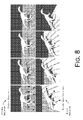
- FIG. 8 is a diagram of results of an exemplary method of footprint editing.
- FIG. 9 is a diagram of results of an exemplary method path editing.
- FIG. 10 is a diagram of results of an exemplary method of combined footprint editing, path editing, and keyframe editing.
- FIG. 11 is a diagram of results of an exemplary method of handle-based deformation editing.
- FIG. 12 is a diagram of results of an exemplary method of mesh deformation filtering.
- FIG. 13 is a diagram of results of an exemplary method of spacetime morphing.
- This disclosure describes gradient domain editing of animated meshes.
- the animated mesh is edited by applying Laplacian mesh editing techniques in the spacetime domain.
- editing a static mesh in the gradient domain is known—that is, editing one frame that contains one snapshot of the mesh
- exemplary systems and methods described herein automatically edit the entire sequence as it progresses temporally, based on received edits at sparsely selected individual frames.
- exemplary systems generalize gradient domain static mesh editing to animated mesh editing, i.e., to deforming mesh sequence editing.
- the system adjusts the meshes at keyframes to satisfy the constraints, and then propagates the constraints and deformations at the keyframes to the entire sequence to generate new deforming mesh sequences.
- the system enables several novel applications, including footprint editing, path editing, handle based deformation mixing, deformation filtering, and space-time morphing.
- the alternating least-squares method obtains high-quality deformation results at keyframes.
- An animated mesh is a deforming mesh sequence—across multiple video frames—that forms the underlying 3-dimensional geometrical structure of a moving foreground figure or other 2-dimensional object in a video. That is, the mesh is a mathematical construction of triangles or other geometric shapes joined at their vertices that realistically simulates a moving shape—such as a moving animal or person—in a video sequence.
- the moving shape can be well-approximated by changing the position of vertices where triangles meet and/or the visual rotation of the triangles, thereby changing the 2-dimensional size and shape of the triangles. This allows control of the visual aspect of the mesh construction as needed to simulate a moving 3-dimensional object on a 2-dimensional display surface. More realism can be attained by using smaller triangles to provide more detail, however this raises processing costs.
- the mesh is usually covered with an appealing outer layer to visually hide the mesh structure and simulate the depicted figure.
- the exemplary system is keyframe-based and edits an animated mesh sequence at selected frames and/or selected trajectory handles so that the edits are propagated to the rest of the mesh sequence via a least-squares energy technique.
- the exemplary alternating least-squares technique is embodied in an engine that lies at the heart of diverse editors, which can provide advanced editing.
- the advanced editing capabilities provided herein save the user a great deal of manual work.
- the user can reposition footprints of a walking mesh figure over a new path and/or new terrain and the system automatically conforms the walking figure to the new footprints.
- a user-sketched curve allows the system to automatically provide a new motion path to the animated figure. Movements of one animated figure can be transferred to a different figure in a different mesh sequence.
- Signal processing can be applied to provide caricature and cartoon effects.
- the user can also select spacetime morphing to change the shape and motion of one animated figure into the shape and motion of another figure over a short time interval.
- FIG. 1 shows an exemplary system 100 in which a computing device 102 hosts an exemplary animated mesh editor 104 .
- the computing device 102 may be a desktop or notebook computer, or other computing device with a processor, memory, data storage, etc.
- An initial animated mesh sequence 106 (shown stylistically as only the 2-dimensional foreground object that is based on the mesh—i.e., a horse) is input as the raw starting sequence 106 for the animated mesh editor 104 to edit.
- a user selects a frame 108 of the initial video 106 and drags a part of the horse to a new position onscreen. For example, the user might lift the head or place the legs, tail, ears, and/or torso, in new position(s).
- the selected frame 108 being edited becomes an initial keyframe for changes which are then propagated to the remaining frames of the video: i.e., to the new animated mesh sequence 110 .
- Other frames in the animated mesh sequence 106 may also be selected and edited in the same manner.
- Results are more natural than conventional mesh editing techniques because the exemplary animated mesh editor 104 uses per-vertex local rotations, which prevent severe distortion.
- the exemplary mesh editor 104 also correctly propagates handle-editing results from the edited keyframe(s) 108 to intermediate frames.
- the exemplary animated mesh editor 104 defines a single local coordinate frame for each handle, and represents the vertices in each handle using local coordinates for natural propagation that avoids distortion.
- the animated mesh editor 104 can port a walking sequence from a planar surface to uneven terrain.
- the animated mesh editor 104 can provide these advanced editing effects through such advanced modes as footprint editing and path editing for walking and running.
- footprint editing the user merely drags footprints to new positions—even over uneven terrain—and the animated walking object walks or runs in the new footprint positions.
- path editing the user merely designates a line or a complex curve, and the animated object walks the new curve.
- a handle-based deformation mode allows the user to easily transfer handles from one moving object—e.g., a human dancer—to another moving object—e.g., a waving cloth—to make a dancing cloth that follows the movements of the human dancer.
- Mesh deformation filtering allows animated mesh movements to be caricatured or exaggerated for special effect, such as for making a cartoon.
- Spacetime morphing allows the exemplary animated mesh editor 104 to smoothly transition the shape and motion of one object into the shape and motion of a second object. For example, a running man can be made to smoothly morph into a crawling baby in a certain number of strides.
- FIG. 2 shows one example configuration of the exemplary animated mesh editor 104 of FIG. 1 , in greater detail.
- the illustrated implementation is only one example configuration, for descriptive purposes. Many other arrangements of the components of an exemplary animated mesh editor 104 are possible within the scope of the subject matter.
- Such an exemplary animated mesh editor 104 can be executed in hardware, software, or combinations of hardware, software, firmware, etc.
- the exemplary animated mesh editor 104 includes a gradient domain deformation engine (“deformation engine”) 202 , a control mesh transfer engine 204 , an environmental constraints engine 206 , and a deformation & constraints propagator 208 .
- the deformation engine 202 further includes a keyframe editor 210 and a boundary condition definition engine 212 .
- the keyframe editor 210 may further include a user interface 214 that includes a frame selector 214 ( a ) and a handle selector 214 ( b ), a subspace solver 216 that uses a coarse control mesh 218 and provides initial vertex positions 220 , and an alternating least-squares engine 222 .
- the alternating least-squares engine 222 includes a local rotation solver 224 and a vertex position solver 226 .
- the boundary condition definition engine 212 inputs handle edits 228 and includes a handle trajectory editor 230 .
- the control mesh transfer engine 204 operates on a first frame control mesh 232 as a starting point.
- the deformation & constraints propagator 208 further includes a mesh reconstructor 234 , which may include a per-vertex rotation interpolator 236 , and a differential coordinates generator 238 .
- the exemplary animated mesh editor 104 receives the animated mesh sequence 106 (also shown in FIG. 1 ) as input and creates the new animated mesh sequence 110 as output.
- the exemplary animated mesh editor 104 is keyframe-based.
- the user can choose to edit any frame in the original mesh sequence 106 as well as any handle on that frame. Handles will be described in greater detail below.
- the visual environment may induce constraints at certain frames—for instance, a walking mesh figure should walk over a hill, not through it. Each frame with environment-induced or user-supplied constraints subsequently becomes a keyframe 108 . The location of these constraints varies among different keyframes 108 . Adapting the original deforming mesh 106 to satisfy such sparse and irregularly distributed constraints at unevenly spaced keyframes 108 is conventionally a daunting task.
- the keyframe editor 210 first adjusts the meshes at the keyframes 108 to satisfy these constraints, and then the deformation & constraints propagator 208 smoothly transfers the constraints and deformations from keyframes 108 to the entire sequence 106 to generate a new deforming mesh sequence 110 .
- the keyframe editor 210 harnesses the power of the subspace (deformation) solver 216 and the two-pass linear methods that are inherent in the alternating least-squares engine 222 to achieve high-quality deformations.
- the boundary condition definition engine 212 effectively defines boundary conditions for all frames in a sequence 110 using an exemplary handle trajectory editor 230 . Implementations of the exemplary animated mesh editor 104 have been successfully applied to the above-introduced editing scenarios that possess increasing complexity, including footprint editing, path editing, temporal filtering, handle-based deformation mixing, and spacetime morphing.
- the deformation & constraints propagator 208 smoothly transfers both the deformations and constraints at keyframes 108 to the rest of the frames in the sequence 110 .
- the deformations are defined as local transforms of the differential coordinates between a pair of original and deformed keyframes 108 .
- the propagated deformations are used by the differential coordinates generator 238 to generate target differential coordinates for each frame.
- the mesh reconstructor 234 uses boundary conditions to perform subsequent mesh reconstruction from target differential coordinates. Therefore, the handle trajectory editor 230 uses a least-squares technique to propagate the constraints at keyframes 108 to the rest of the frames to serve as boundary conditions.
- the exemplary keyframe editor 210 introduces an accurate nonlinear solution for static mesh deformation of individual keyframes 108 .
- a deformed mesh should satisfy deformation constraints while optimally preserving the local relative configurations among neighboring vertices under rotation invariant criteria. This has motivated the introduction of a local frame at each vertex in conventional techniques, where a solution of the deformed mesh is obtained by solving the altered local frames and vertex positions in two sequential linear steps.
- ⁇ circumflex over (v) ⁇ i and v i represent the same vertex in the original and deformed meshes, respectively.
- Equation (1) over all vertices gives rise to an overdetermined linear system for vertex positions and can be solved using least-squares if a boundary condition is given.
- Equation (2) It is suboptimal to first solve local frames and then solve vertex positions in the sense that they may not optimally satisfy the overdetermined system expressed in Equation (1). Instead, it is more optimal to solve both local frames and vertex positions simultaneously by minimizing the objective function in Equation (2):
- V represents the set of constrained vertices on handles
- C is the positional constraint matrix
- U is the target positions of the constrained vertices.
- Equation (2) Simultaneously optimizing all the unknowns in Equation (2) gives rise to an expensive nonlinear least-squares problem. Fortunately, an initial inaccurate solution to this nonlinear problem can be refined until convergence is reached.
- the alternating least-squares engine 222 can iterate two simpler and more efficient least-squares steps, which are responsible for improving, respectively, the estimation of the local frames and the vertex positions. The first of these two steps minimizes Equation (2) by fixing the vertex positions and optimizing R i 's only. The second step does the opposite.
- Equation (2) becomes equivalent to minimizing the local objective function in Equation (3), once for each local frame:
- the optimal rotation matrix R i can be conveniently obtained from a closed-form quaternion-based solution: a local shape matching problem.
- the problem has a unique solution as long as v i has two or more 1-ring neighbors and v i is not collinear with them. Since the number of vertices in a 1-ring neighborhood is practically bounded, solving the local frames at all vertices using this closed-form solution has a linear complexity.
- the keyframe editor 210 successfully minimizes Equation (2) using a combination of local shape matching and sparse linear systems without the expensive global shape matching that is typically used in nonlinear optimization.
- the alternating least-squares convergence can be guaranteed, since the two alternating steps respectively obtain optimal least-squares solutions with respect to the subset of the variables they optimize.
- the local rotation solver 224 optimizes the rotations using Horn's closed-form solution, which has the same least-squares objective function in Equation (2).
- the vertex position solver 226 optimizes vertex positions while fixing rotations. Both steps monotonically decrease the least-squares objective function defined in Equation (2) and therefore guarantee convergence.
- Equation (2) An initial solution to Equation (2) is still needed to start the iterations.
- One conventional subspace method uses a coarse control mesh to obtain an approximate solution inside a subspace (see Huang J., Shi, X., Liu, X, Zhou, K. Wei, L.-Y., Teng, S.-H., Bao, H., Guo, B., and Shum, H.-Y, “Subspace gradient domain mesh deformation,” ACM Transactions on Graphics, 2006, 25, 3, 1126-1134: the “Huang 2006 reference,” which is incorporated herein by reference, in its entirety).
- the subspace solver 216 uses a coarse control mesh 218 to provide such an approximate subspace solution to serve as a desirable starting point for initializing the alternating least-squares engine 222 .
- the subspace solver 216 merely requires positional constraints. Even though the iterations of the alternating least-squares engine 222 involve rotations, the initial rotations can be estimated from the initially deformed vertex positions supplied by the subspace solver 216 . As a result, the exemplary keyframe editor 210 can also work with positional constraints only.
- the alternating least-squares engine 222 can achieve smooth and visually pleasing results in less than ten iterations.
- the running time for each iteration is 0.03 second on a 3.2 GHz Pentium processor for a mesh with 10,000 vertices (Davis, T. A., “User Guide for CHOLMOD,” Tech. rep ., University of Florida, 2006).
- the exemplary alternating least-squares engine 222 can reach a more globally optimal solution than conventional methods, it can achieve better visual results as well. Many conventional methods need user-supplied rotational constraints while the alternating least-squares engine 222 does not. Although in one implementation, the alternating least-squares engine 222 does not explicitly enforce the smoothness of the rotation field over the deformed mesh as in some conventional techniques, the local frames as well as the resulting rotation field obtained are in fact smoothly varying because they are extracted from 1-ring neighborhoods as in Equation (3) and the 1-ring neighborhoods of adjacent vertices have partial overlap.
- FIG. 3 compares results of the exemplary keyframe editor 210 with a conventional subspace technique in the Huang 2006 reference cited above.
- One issue is that self-intersections in the conventional control mesh as well as its coarse resolution can result in unnatural deformation results from the subspace technique while the alternating least-squares engine 222 can successfully eliminate the problems in such results.
- FIG. 3( a ) shows the rest pose of a mesh-based figure.
- FIG. 3( b ) shows the control mesh. Since the head and hand of the illustrated dinosaur figure are too close to each other, the subspace technique causes self-intersections 302 in the control mesh. As a result, the subspace method produces the unnatural results shown in FIG. 3( c ), while the exemplary alternating least-squares engine 222 preserves the details of the original shape very well, as shown in FIG. 3( d ).
- the exemplary keyframe editor 210 built upon the subspace method in the Huang 2006 reference, further provides additional control over deformation results, including volume constraint, skeleton constraint, and projection constraint. Therefore, the exemplary gradient domain deformation engine 202 with its alternating least-squares keyframe editor 210 is a more convenient tool for interactive keyframe editing.
- the user interface 214 allows the user to choose to edit an arbitrary subset of frames.
- these chosen frames are called keyframes 108 , because a frame that contains user-provided or environment-imposed constraints becomes a keyframe 108 for modifying the intermediate frames between the keyframes 108 .
- the user can choose to edit an arbitrary subset of handles.
- a handle is defined as a subset of neighboring vertices within the same frame.
- L k is the matrix for computing spatial Laplacian differential coordinates at the k-th frame
- ⁇ circumflex over (d) ⁇ i k is the vector of differential coordinates at the i-th vertex of the original mesh at the k-th frame
- R i k is the local rotation matrix at v i k
- ⁇ t R i k represents the differences of corresponding rotation matrices in consecutive frames
- C k , V k , and U k are similar to C, V, and U in Equation (2).
- Equation (4) enforces temporal coherence of local rotations.
- terms accommodating additional constraints have been left out, such as volume preservation.
- Directly optimizing such a nonlinear objective function with respect to vertex positions and local rotations across all the frames is extremely expensive.
- simultaneous optimization in both spatial and temporal domains typically does not preserve very well the shape of the meshes at individual frames because the solution needs to provide a tradeoff between these two domains.
- the deformation engine 202 obtains a numerically suboptimal solution, which nonetheless is capable of producing visually pleasing results. Once constraints are set up, the deformation engine 202 performs the following steps to minimize Equation (4) and produce a new deforming mesh sequence 110 that is consistent with all constraints while maintaining temporal coherence of both local rotations and handle positions.
- Equation (4) its first and third terms are minimized by the second and last steps (above) respectively for the keyframes 108 and intermediate frames.
- the second term of Equation (4) is reduced in the third step above.
- the positional constraints at intermediate frames are automatically set up by the fourth step above. Compared to simultaneously optimizing all of Equation (4)'s unknowns at once, the above sequential steps can preserve shapes better at individual frames. More details regarding the control mesh transfer engine's 204 automatic control mesh generation (the first step) and the handle trajectory editor's 230 handle propagation (the fourth step) follow.
- FIG. 4 shows a comparison between the gradient domain editing steps and methods implemented in the exemplary animated mesh editor 104 and a conventional multi-resolution method for mesh editing.
- FIG. 4( a ) shows an original, unedited, box twisting sequence.
- FIG. 4( b ) shows the result from the exemplary animated mesh editor 104 .
- FIG. 4( c ) shows the result from the multi-resolution editing method.
- the keyframe editor 210 receives the original first frame 402 ; edits the first frame 404 , which becomes a keyframe; and then propagates the deformation at the first frame 404 to the entire sequence: frames 406 and 408 .
- the exemplary animated mesh editor 104 generates natural results ( 406 and 408 ) while the results from the multi-resolution method have severe distortions: frames 410 and 412 . This is because the multi-resolution method is based on local detail vectors only while the exemplary animated mesh editor 104 is based on local rotations.
- the deformation and constraints propagator 208 performs the critical function of correctly propagating the handle editing results from the keyframes 108 to all intermediate frames since altered handles serve as new boundary conditions when the meshes at the intermediate frames are deformed and reconstructed. Because there are multiple vertices in the same handle and interpolating each vertex position individually at intermediate frames would severely distort the overall shape of the handle, these vertices are forced to move together rigidly using the extracted average translation and rotation.
- a single local coordinate frame is defined for each handle and represents the vertices in that handle using their local coordinates.
- m 0, . . . , n p ⁇ 1 ⁇ , where ⁇ v im k
- m 0, . . . , n p ⁇ 1 ⁇ is the set of vertices in the handle, and c i k and columns of F i k define the origin and axes of the local coordinate frame.
- C i k can be the centroid of the vertices and the initial axes can be defined arbitrarily since in one implementation the exemplary technique only considers the rotation between the initial and altered axes.
- the boundary condition definition engine 212 can define a piecewise linear curve in the temporal domain and then ⁇ c i k 0 ⁇ k ⁇ n f ⁇ is the set of vertices of this curve. ⁇ F i k 0 ⁇ k ⁇ n f ⁇ can also be used to define the axes of the local coordinate frames at these vertices.
- handle trajectory editor 230 determines the new positions and rotations for the rest of the vertices on the curve.
- handle trajectory editing can be cast as a temporal curve editing problem.
- ⁇ i k and c i k represent the original and new handle centroids
- N k represents the index set of the immediate neighbors of c i k
- ⁇ i k ⁇ l represents the local coordinates of ⁇ i l in the local frame— ⁇ circumflex over (F) ⁇ i k —defined at ⁇ i k in the original curve.
- Corresponding handle rotations at keyframes 108 are simply interpolated over the rest of the vertices on the curve to determine the orientation of all the new local coordinate frames, ⁇ F i k ⁇ , at these vertices. Once these altered local frames are known, Equation (5) over all unconstrained vertices gives rise to an overdetermined linear system for vertex positions and can be solved using least-squares. Such a least-squares problem is solved for each curve. Since the number of vertices on a curve is relatively small, the least-squares problem can be solved very quickly. The new world coordinates of the vertices inside each handle at an intermediate frame can be obtained by maintaining their original local coordinates in the new local coordinate frame at that handle.
- FIG. 5 shows a comparison of results from the exemplary handle trajectory editor 230 and those provided by a conventional simple local translation at each vertex. It is apparent that conventional local translation shrinks the size of the horse leg 502 while results from the exemplary handle trajectory editor 230 remain natural 504 .
- frames # 1 and # 4 in the sequence are set as keyframes.
- FIG. 5( b ) shows frame # 1 edited: i.e., before editing 506 and after editing 508 .
- FIG. 5( c ) shows edited results at the second frame in the sequence (frame # 2 ).
- the exemplary handle trajectory editor 230 generates natural results 510 at frame # 2 , while editing based on conventional simple local translation generates severe distortion 512 at frame # 2 in the edited leg.
- the control mesh transfer engine 204 exploits the frame-to-frame deformation of the finer mesh to automatically construct an altered control mesh for each keyframe 108 in the sequence 106 .
- the altered control mesh has altered vertex positions but the same mesh connectivity.
- the control mesh transfer engine 204 first binds the control mesh to the finer mesh at the first frame, and then uses the same binding throughout the rest of the sequence 106 .
- the control mesh transfer engine 204 simply uses their linear blend as ⁇ tilde over (v) ⁇ j 's new world coordinates. Experimentation reveals that even uniform weighting in the linear blending can achieve good results.
- FIG. 6 shows two typical results provided by the control mesh transfer engine 204 . As illustrated on the left, first frames 602 and 604 are shown with assigned control mesh in two different deforming mesh sequences. On the right, the automatically transferred control meshes are shown at respective later frames 606 and 608 .
- FIG. 7 shows an exemplary method 700 of animated mesh editing 700 .
- the exemplary method 700 may be performed by hardware, software, or combinations of hardware, software, firmware, etc., for example, by components of the exemplary animated mesh engine 104 .
- An animated mesh is a deforming mesh sequence—a sequence of video frames that typically include a visual foreground object generated or depicted in terms of a geometrical model of triangles (or other polygons) connected at their vertices to make a geometrical structure composed of the triangles—the mesh.
- the mesh can be mathematically generated or manipulated. For visual effect, the mesh is typically covered with a visual skin to portray a moving person or animal.
- the animated mesh is edited in the spacetime domain by applying alternating least-squares to a Laplacian mesh editing technique.
- editing a static mesh in the gradient domain is known—that is, editing one frame that contains one snapshot of the mesh
- the exemplary method 700 automatically edits the entire sequence as it progresses temporally, from edits of sparsely selected individual frames.
- the exemplary method 700 includes transferring a control mesh modified from the first frame of the received sequence, across the rest of the frames. This provides constraints and boundary conditions for later calculations. The method also accounts for environment-induced constraints.
- Applying alternating least-squares in the spacetime domain includes receiving initial information from a subspace solving technique and iterating between solving local vertices and solving local rotations.
- Creating a new animated mesh sequence includes propagating the deformations and constraints at the edited keyframes to intermediate frames in the sequence. In one implementation, this involves handle trajectory editing, in which a least-squares technique propagates the constraints at keyframes to the rest of the frames to serve as boundary conditions.
- the exemplary animated mesh editor 104 described as an engine above is powerful and the processes that it implements may save the user a great deal of manual editing labor. Sometimes it may become tedious for the user to generate more advanced editing effects. For example, porting a walking sequence from a planar surface to an uneven terrain conventionally requires a great deal of user interaction.
- advanced editing modes are described which can be built on top of the exemplary method 700 or on top of the exemplary animated mesh editor 104 .
- footprint editing and path editing are specifically designed for motion similar to walking and running.
- Handle-based deformation mixing can be useful for duplicating handle movements from a source sequence to a target sequence.
- the exemplary techniques not only alter the shape of the deforming mesh sequence but also the overall motion of the shape, which is very hard to achieve using conventional methods, such as multi-resolution mesh editing.
- the moving mesh figure leaves a so-called footprint there.
- the footprint is defined within an interval of the frames in which a handle remains fixed on the ground.
- the user revises the original footprints, and lets the exemplary method automatically adapt the original walking motion to the new footprints.
- the user first defines a handle that represents the foot. After that, the footprints are automatically detected by checking within an interval if the position of the handle is unchanged or the changes are less than a threshold.
- a frame that contains a footprint is automatically set as a keyframe.
- the exemplary method allows the user to either directly place or project footprints onto a terrain.
- the footprint can be rotated during projection by aligning the local surface normal of the terrain and the up-axis of the local frame at the footprint.
- FIG. 8 shows exemplary footprint editing.
- the user relocates the footprints, and the exemplary method automatically generates the edited sequence.
- a planar walking sequence is adapted to stair walking simply by dragging left and right footprints to new locations.
- the user only has to relocate the footprints to the stairs, and the exemplary method 700 or the exemplary animated mesh editor 104 automatically generates the stair walking sequence.
- FIG. 9 shows the path of a planar and linear walking sequence (i.e., the top row of frames in FIG. 8 ) that has been adapted to a user-sketched curve 902 in FIG. 9 .
- an exemplary method To estimate the motion path of the original mesh sequence, an exemplary method first projects the centroids of the meshes in the original sequence onto the ground, and then fits a B-spline curve through these projected points.
- the path editing method builds correspondence between the original path p orig (s) and the new one p new (t) using arc length.
- p orig (sk) is the point for frame k on the original path, and it corresponds to p new (tk) on the new path.
- the method uses the rigid body transform between the two local frames at these two points to transform the mesh at frame k in the original sequence so that the transformed mesh has a position and orientation consistent with the new path.
- a footprint may last a few frames, each of which may have different transforms, the same footprint in the original sequence may be transformed to multiple different locations.
- the exemplary path method simply averages these multiple locations and sets the result as the corresponding footprint for the edited sequence.
- an exemplary system applies the exemplary spacetime techniques described above with respect to the animated mesh editor 104 to these transformed meshes while considering the new footprints as handle constraints.
- FIG. 10 shows a more complex example where a straight run, in which the original deforming mesh sequence moves along a straight line on a planar surface, is adapted to a curved path on an uneven terrain.
- the user has adjusted the pose of the horse's head to make the animation look more natural.
- a straight run is first adapted to a curved path on an uneven terrain—the user first makes the horse move along a curve using path editing. Then, the user adapts the sequence onto the terrain using footprint editing.
- Deformation transfer has been used for making a static mesh follow the deformation sequence of a second mesh.
- Conventional deformation transfer algorithms require a complete or nearly complete correspondence between triangles on the two meshes.
- An exemplary deformation mixing method starts with two deforming meshes and generates a new third sequence that mixes the large-scale deformations of the first mesh sequence with the small-scale deformations of the second mesh sequence.
- the exemplary deformation mixing method uses the motion trajectories of a sparse set of handles on the first mesh to define the large-scale deformations of the new mesh sequence, and forces the corresponding handles on the second mesh to follow these trajectories in the new mesh sequence.
- a user only has to define the correspondence between handles on the two starting meshes.
- Each handle on the two starting meshes generates a motion trajectory within its own respective mesh sequence. Since there may be global differences between two corresponding trajectories, directly forcing the second handle to follow the trajectory of the first one may produce noticeable inconsistencies between the transferred handle trajectory and the rest of the deformation on the second mesh. Therefore, the exemplary method first aligns the two corresponding trajectories using a global transformation, including scaling, translation, and rotation, between them. After that, the exemplary method sets the transformed handle positions and rotations from the first trajectory as constraints for the corresponding handle on the second mesh. The method repeatedly sets up such constraints on the second mesh for all the handles defined on the first mesh, and then applies the spacetime solving techniques (e.g., as executed by the animated mesh editor 104 ) to deform each frame of the second sequence.
- the spacetime solving techniques e.g., as executed by the animated mesh editor 104
- FIG. 11 shows exemplary deformation mixing results.
- the method mixes human motion, such as running and boxing, with a second figure in a second sequence, e.g., a cloth animation (in this case, a flag blowing in the wind).
- a cloth animation in this case, a flag blowing in the wind.
- the moving wrinkles of the flag are well preserved using the exemplary method.
- the top row of FIG. 11 shows example MoCAP data for running.
- the bottom row shows the motions of the running sequence of the top row, mixed with the flag animation.
- the wrinkles on the cloth are originally generated using cloth simulation.
- the user defines corresponding handles between the human model and the cloth. For instance, handles on the arms of the human model can correspond to the upper corners of the cloth while handles on the feet of the human model correspond to lower corners of the cloth.
- an exemplary mesh deformation filtering method can apply signal processing techniques to produce filtered versions of the trajectories, and then use these filtered trajectories as constraints on the handles to deform the original mesh sequence.
- the mesh surface itself has characteristic small-scale details in addition to frame-to-frame deformations.
- the exemplary deformation filtering method alters the latter but preserves the details. Performing filtering at the level of handles allows the exemplary method to achieve this goal, while on the contrary, directly filtering the trajectory of each vertex would destroy such details.
- the exemplary mesh deformation filtering method further allows the user to create a hierarchy among the handles.
- the root of the hierarchy is typically the centroid of the entire mesh.
- the centroids of the meshes at all frames define the trajectory of the root.
- All of the user-defined handles are children of the root.
- the user can optionally set one handle as a child of another handle.
- the trajectory of each handle is transformed to the local coordinate frame at its parent. All these relative trajectories, as well as the global trajectory at the root, are subject to filtering. However, detected footprints may be exempted from filtering to avoid footskating.
- the filtered relative trajectories are transformed back to the world coordinate system before being used as constraints in the exemplary spacetime solving techniques, e.g., as implemented in the animated mesh editor 104 .
- LOG is the Laplacian of the Gaussian
- X*(t) is the original signal
- X*(t) is the filtered signal.
- One implementation of the exemplary mesh deformation filtering method utilizes this filter successfully.
- FIG. 12 shows an exemplary filtering example.
- FIG. 12( a ) shows the user-specified handles.
- FIG. 12( b ) shows the initial hierarchy among the user-specified handles defined for the illustrated dinosaur. The trajectory of each handle is filtered to create cartoon style motion. To maintain existing contact constraints, the foot trajectories are not filtered.
- FIG. 12( c ) shows one frame in the original deforming mesh sequence.
- FIG. 12( d ) shows a filtered result (i.e., exaggerated, cartoon-like caricature of motion) for the frame, with the silhouette of the original shape in the background.
- Spacetime morphing is introduced herein as a new application based on the above-described animated mesh editing methods.
- the exemplary spacetime morphing method morphs a source deforming mesh A s to a target deforming mesh A t in terms of both shape and deformation. For example, given a walking dinosaur as the source mesh and a walking lion as the target mesh, the exemplary spacetime morphing method generates a new sequence, in which the shape of the dinosaur is morphed into the shape of the lion while the dinosaur's walking transitions into the lion's walking.
- both initial deforming sequences are remeshed so that every pair of corresponding frames has the same topology.
- the exemplary method first performs cross-parameterization between the first pair of corresponding frames as in Kraevoy, V., and Sheffer, A., “Cross-parameterization and compatible remeshing of 3-d models,” ACM Transactions on Graphics, 2004, 23, 3, 861-869, which is incorporated herein by reference.
- ⁇ tilde over (V) ⁇ c,k may be computed as described above with respect to the control mesh transfer engine 204 —using the original mesh topology.
- the exemplary method designates a temporal morph interval for A s and A t respectively. Assuming the interval is (f 1 s , f 2 s ) for the source and (f 1 t ,f 2 t ) for the target (the number of frames in the two intervals can be different), the method aligns the two mesh sequences in the world coordinate system. This may be achieved by computing an optimal rigid transformation to make the mesh at f 1 t align with the mesh at f 1 s , or alignment can be specified by user input. The computed transformation is then applied to every frame in A t to align the two sequences. Finally, the exemplary method blends the portion of the two sequences inside the morph intervals.
- the method calculates a parameter t ( ⁇ [0,1]) to sample a source and target mesh from (f 1 s , f 2 s ) and (f 1 t , f 2 t ) respectively.
- the local frames and Laplacian differential coordinates of the sampled meshes are interpolated using a method similar to the one presented in Lipman, Y., Sorkine, O., Levin, D., and Cohen-Or, D., “Linear rotation-invariant coordinates for meshes,” ACM Transactions on Graphics, 2005, 24, 3, which is incorporated herein by reference.
- the exemplary method reconstructs a mesh for the blended frame from the interpolated Laplacian coordinates.
- the exemplary method carefully tracks constraints, such as footprints in walking motion, in the spacetime morphing.
- constraints such as footprints in walking motion
- the exemplary method marks the frames where a constraint should be satisfied and maintains that constraint when the method solves the meshes for the blended frames.
- FIG. 13 demonstrates the above-described exemplary spacetime morphing method.
- the exemplary method concatenates dinosaur walking with lion walking by morphing the dinosaur into the lion in one-and-a-half walking cycles (starting out with the right foot of the dinosaur).
- the middle three images in FIG. 13 show how the shape and motion of the two original sequences are blended to generate the final results.
- An exemplary system prior to interactively editing a deforming mesh sequence, transfers the control mesh at the first frame of the received mesh sequence to all frames, and computes the mean-value matrix from this control mesh to the fine mesh of each frame.
- Laplacian matrices used for minimizing Equation (4), above, can be pre-computed.
- the exemplary system obtains sparse coefficient matrices, and pre-computes the factorization of such sparse matrices for each frame.
- An editing session may have both online and offline stages.
- the exemplary system can provide interactive frame rates. This is achieved by using the subspace solver 216 to show approximate initial solutions quickly.
- the alternating least-squares engine 222 may be activated by the user only when the subspace solver 216 cannot produce satisfactory results.
- the exemplary system may perform offline computation to obtain the entire edited sequence, for example, to solve for each frame when there are more than 100 frames in the sequence.
Abstract
Description
v j −v i =R i {circumflex over (v)} i→j , jεN i, (1)
where Ni represents the index set of the 1-ring neighbors of vi, Ri is a 3×3 rotation matrix that represents the altered local frame at vi, and {circumflex over (v)}i→j represents the local coordinates of {circumflex over (v)}j in the local frame {circumflex over (R)}i, at {circumflex over (v)}i in the original mesh. The columns of Ri consist of the three orthonormal axes, (b1 i,b2 i,Ni), of the local frame. Once the altered local frames are known, Equation (1) over all vertices gives rise to an overdetermined linear system for vertex positions and can be solved using least-squares if a boundary condition is given.
where vi, vj and Ri are unknowns, V represents the set of constrained vertices on handles, C is the positional constraint matrix, and U is the target positions of the constrained vertices.
where the optimal rotation matrix Ri can be conveniently obtained from a closed-form quaternion-based solution: a local shape matching problem. The problem has a unique solution as long as vi has two or more 1-ring neighbors and vi is not collinear with them. Since the number of vertices in a 1-ring neighborhood is practically bounded, solving the local frames at all vertices using this closed-form solution has a linear complexity.
where Lk is the matrix for computing spatial Laplacian differential coordinates at the k-th frame, {circumflex over (d)}i k is the vector of differential coordinates at the i-th vertex of the original mesh at the k-th frame, Ri k is the local rotation matrix at vi k, Δt R i k represents the differences of corresponding rotation matrices in consecutive frames, and Ck, Vk, and Uk are similar to C, V, and U in Equation (2). The second term in Equation (4) enforces temporal coherence of local rotations. In this objective function, for the sake of clarity, terms accommodating additional constraints have been left out, such as volume preservation. Directly optimizing such a nonlinear objective function with respect to vertex positions and local rotations across all the frames is extremely expensive. More importantly, simultaneous optimization in both spatial and temporal domains typically does not preserve very well the shape of the meshes at individual frames because the solution needs to provide a tradeoff between these two domains.
-
- First, since obtaining the initial solution for alternating least-squares requires a
coarse control mesh 218 to make the solution applicable in the spacetime domain, the controlmesh transfer engine 204 creates and/or transfers a control mesh for each frame in theinput sequence 106. In one implementation, to minimize user interaction, theanimated mesh editor 104 merely requires a firstframe control mesh 232 and automatically generates a control mesh for each subsequent frame by adjusting thefirst one 232. - Second, the mesh at each
keyframe 108 is deformed to satisfy the positional constraints at thatkeyframe 108 via the alternating least-squares engine 222 introduced above. As an output, the alternating least-squares engine 222 provides an altered local coordinate frame as well as an associated rotation at each vertex over the deformed mesh. - Third, the per-
vertex rotation interpolator 236 smoothly interpolates these rotations for each vertex of thekeyframes 108 to obtain dense rotational constraints at each intermediate frame. Rotations can be represented as unit quaternions, and the logarithm of the quaternions can be interpolated using Hermite splines. Those frames at the very beginning or end of themesh sequence 106 may not be bracketed by sufficient number ofkeyframes 108 and are therefore only linearly interpolated or not interpolated at all. The user can optionally designate an influence interval for akeyframe 108 to have finer control over the interpolation. - Fourth, the
handle trajectory editor 230 extracts an average translation and rotation for each handle from the translations and rotations associated with individual vertices in the handle. Since each handle has its own temporal trajectory in theoriginal mesh sequence 106, this trajectory is automatically edited and updated using the extracted average translations and rotations atkeyframes 108 to guarantee its temporal consistency. - Lastly, the
mesh reconstructor 234 solves a deformed mesh for each intermediate frame (between the keyframes 108) using the interpolated rotational constraints as well as the positional constraints from the updated handles. Since there is already a rotational constraint at each free vertex, themesh reconstructor 234 can obtain a deformed mesh quickly by simply solving the overdetermined linear system in Equation (1) without invoking the moreexpensive subspace solver 216. A few iterations of the alternating least-squares engine 222 can optionally be applied to improve the deformed mesh.
- First, since obtaining the initial solution for alternating least-squares requires a
c i l −c i k =F i k ĉ i k→l , lεN k, (5)
where ĉi k and ci k represent the original and new handle centroids, Nk represents the index set of the immediate neighbors of ci k, the term |Nk|≦2; and the term ĉi k→l represents the local coordinates of ĉi l in the local frame—{circumflex over (F)}i k—defined at ĉi k in the original curve. Corresponding handle rotations at
Vf=WVc, (6)
where Vf represents vertices of the finer mesh, Vc represents vertices of the control mesh, and W is a matrix of mean value coordinates. In the current context, given the first
X*(t)=X(t)−X(t){circle around (×)}LOG, (7)
where LOG is the Laplacian of the Gaussian, X*(t) is the original signal, and X*(t) is the filtered signal. One implementation of the exemplary mesh deformation filtering method utilizes this filter successfully.
Claims (17)
Priority Applications (1)
| Application Number | Priority Date | Filing Date | Title |
|---|---|---|---|
| US11/772,001 US7843456B2 (en) | 2007-06-29 | 2007-06-29 | Gradient domain editing of animated meshes |
Applications Claiming Priority (1)
| Application Number | Priority Date | Filing Date | Title |
|---|---|---|---|
| US11/772,001 US7843456B2 (en) | 2007-06-29 | 2007-06-29 | Gradient domain editing of animated meshes |
Publications (2)
| Publication Number | Publication Date |
|---|---|
| US20090002376A1 US20090002376A1 (en) | 2009-01-01 |
| US7843456B2 true US7843456B2 (en) | 2010-11-30 |
Family
ID=40159836
Family Applications (1)
| Application Number | Title | Priority Date | Filing Date |
|---|---|---|---|
| US11/772,001 Active 2029-07-30 US7843456B2 (en) | 2007-06-29 | 2007-06-29 | Gradient domain editing of animated meshes |
Country Status (1)
| Country | Link |
|---|---|
| US (1) | US7843456B2 (en) |
Cited By (10)
| Publication number | Priority date | Publication date | Assignee | Title |
|---|---|---|---|---|
| US20090207169A1 (en) * | 2006-05-11 | 2009-08-20 | Matsushita Electric Industrial Co., Ltd. | Processing device |
| US20110292179A1 (en) * | 2008-10-10 | 2011-12-01 | Carlos Hernandez | Imaging system and method |
| US20120008843A1 (en) * | 2009-11-09 | 2012-01-12 | The University Of Arizona | Method for reconstruction of magnetic resonance images |
| US20120113116A1 (en) * | 2010-11-08 | 2012-05-10 | Cranial Technologies, Inc. | Method and apparatus for preparing image representative data |
| US20120308162A1 (en) * | 2010-01-22 | 2012-12-06 | Raymond Pierre Le Gue | Media Editing |
| US20140176661A1 (en) * | 2012-12-21 | 2014-06-26 | G. Anthony Reina | System and method for surgical telementoring and training with virtualized telestration and haptic holograms, including metadata tagging, encapsulation and saving multi-modal streaming medical imagery together with multi-dimensional [4-d] virtual mesh and multi-sensory annotation in standard file formats used for digital imaging and communications in medicine (dicom) |
| US9245070B2 (en) | 2012-04-10 | 2016-01-26 | Bridgestone Americas Tire Operations, Llc | System and method for determining statistical distribution of a rolling tire boundary |
| US20180158241A1 (en) * | 2016-12-07 | 2018-06-07 | Samsung Electronics Co., Ltd. | Methods of and devices for reducing structure noise through self-structure analysis |
| WO2020089817A1 (en) * | 2018-10-31 | 2020-05-07 | Soul Machines Limited | Morph target animation |
| US11922552B2 (en) * | 2020-11-04 | 2024-03-05 | Softbank Corp. | Data processing device, program, and data processing method for generating animation data representing movement of clothing worn by wearer's body |
Families Citing this family (30)
| Publication number | Priority date | Publication date | Assignee | Title |
|---|---|---|---|---|
| JP4613313B2 (en) * | 2005-04-01 | 2011-01-19 | 国立大学法人 東京大学 | Image processing system and image processing program |
| US8749543B2 (en) * | 2006-08-15 | 2014-06-10 | Microsoft Corporation | Three dimensional polygon mesh deformation using subspace energy projection |
| TWI355619B (en) * | 2007-12-04 | 2012-01-01 | Inst Information Industry | System, method and recording medium for multi-leve |
| US8400455B2 (en) * | 2008-01-11 | 2013-03-19 | Sony Corporation | Method and apparatus for efficient offset curve deformation from skeletal animation |
| AU2010259971C1 (en) * | 2009-06-12 | 2017-02-16 | Sunovion Pharmaceuticals Inc. | Sublingual apomorphine |
| US9053553B2 (en) | 2010-02-26 | 2015-06-09 | Adobe Systems Incorporated | Methods and apparatus for manipulating images and objects within images |
| US8860732B2 (en) | 2010-09-27 | 2014-10-14 | Adobe Systems Incorporated | System and method for robust physically-plausible character animation |
| EP2600315B1 (en) * | 2011-11-29 | 2019-04-10 | Dassault Systèmes | Creating a surface from a plurality of 3D curves |
| US20130278626A1 (en) * | 2012-04-20 | 2013-10-24 | Matthew Flagg | Systems and methods for simulating accessory display on a subject |
| US9536338B2 (en) * | 2012-07-31 | 2017-01-03 | Microsoft Technology Licensing, Llc | Animating objects using the human body |
| JP5983550B2 (en) * | 2012-11-30 | 2016-08-31 | 株式会社デンソー | 3D image generation apparatus and 3D image generation method |
| US9336566B2 (en) * | 2012-12-14 | 2016-05-10 | Industry-Academic Cooperation Foundation, Yonsei University | Image deformation method and apparatus using deformation axis |
| US9818216B2 (en) * | 2014-04-08 | 2017-11-14 | Technion Research And Development Foundation Limited | Audio-based caricature exaggeration |
| US20170018110A1 (en) * | 2015-07-15 | 2017-01-19 | Siemens Product Lifecycle Management Software Inc. | Walk simulation system and method |
| US10474927B2 (en) * | 2015-09-03 | 2019-11-12 | Stc. Unm | Accelerated precomputation of reduced deformable models |
| GB2546814B (en) | 2016-02-01 | 2018-10-24 | Naturalmotion Ltd | Animating a virtual object in a virtual world |
| GB2546817B (en) * | 2016-02-01 | 2018-10-24 | Naturalmotion Ltd | Animating a virtual object in a virtual world |
| GB2546815B (en) | 2016-02-01 | 2019-07-03 | Naturalmotion Ltd | Animating a virtual object in a virtual world |
| GB2546820A (en) * | 2016-02-01 | 2017-08-02 | Naturalmotion Ltd | Animating a virtual object in a virtual world |
| US10083525B2 (en) * | 2016-04-11 | 2018-09-25 | Brian Mantuano | Multi-dimensional color and opacity gradation tools, systems, methods and components |
| US10186082B2 (en) * | 2016-04-13 | 2019-01-22 | Magic Leap, Inc. | Robust merge of 3D textured meshes |
| US10169903B2 (en) * | 2016-06-12 | 2019-01-01 | Apple Inc. | Animation techniques for mobile devices |
| US9881647B2 (en) * | 2016-06-28 | 2018-01-30 | VideoStitch Inc. | Method to align an immersive video and an immersive sound field |
| US10304244B2 (en) * | 2016-07-08 | 2019-05-28 | Microsoft Technology Licensing, Llc | Motion capture and character synthesis |
| GB2555605B (en) * | 2016-11-03 | 2020-10-21 | Naturalmotion Ltd | Animating a virtual object in a virtual world |
| US10140764B2 (en) * | 2016-11-10 | 2018-11-27 | Adobe Systems Incorporated | Generating efficient, stylized mesh deformations using a plurality of input meshes |
| CN108269297B (en) * | 2017-12-27 | 2021-06-01 | 福建省天奕网络科技有限公司 | Method and terminal for arranging character movement track in three-dimensional scene |
| US10417806B2 (en) * | 2018-02-15 | 2019-09-17 | JJK Holdings, LLC | Dynamic local temporal-consistent textured mesh compression |
| US11164393B2 (en) * | 2018-09-14 | 2021-11-02 | Microsoft Technology Licensing, Llc | Generating display of a 3-dimensional object |
| US10643365B1 (en) * | 2018-11-20 | 2020-05-05 | Adobe Inc. | Deformation mesh control for a computer animated artwork |
Citations (14)
| Publication number | Priority date | Publication date | Assignee | Title |
|---|---|---|---|---|
| US5929867A (en) | 1996-08-07 | 1999-07-27 | Adobe System Incorporated | Floating keyframes |
| US6088042A (en) | 1997-03-31 | 2000-07-11 | Katrix, Inc. | Interactive motion data animation system |
| US6101235A (en) | 1998-05-27 | 2000-08-08 | General Electric Company | Methods and apparatus for altering spatial characteristics of a digital image |
| US6593925B1 (en) * | 2000-06-22 | 2003-07-15 | Microsoft Corporation | Parameterized animation compression methods and arrangements |
| US20050231512A1 (en) | 2004-04-16 | 2005-10-20 | Niles Gregory E | Animation of an object using behaviors |
| US20050232587A1 (en) | 2004-04-15 | 2005-10-20 | Microsoft Corporation | Blended object attribute keyframing model |
| US6987511B2 (en) * | 2002-10-17 | 2006-01-17 | International Business Machines Corporation | Linear anisotrophic mesh filtering |
| US20060028466A1 (en) | 2004-08-04 | 2006-02-09 | Microsoft Corporation | Mesh editing with gradient field manipulation and user interactive tools for object merging |
| US7151542B2 (en) | 2001-10-17 | 2006-12-19 | Avid Technology, Inc. | Manipulation of motion data in an animation editing system |
| US20060290693A1 (en) | 2005-06-22 | 2006-12-28 | Microsoft Corporation | Large mesh deformation using the volumetric graph laplacian |
| US7184039B2 (en) * | 2000-05-09 | 2007-02-27 | Mental Images Gmbh | Computer-implemented method for generating coarse level meshes for multi-resolution surface editing |
| US7212197B1 (en) * | 1999-02-01 | 2007-05-01 | California Institute Of Technology | Three dimensional surface drawing controlled by hand motion |
| US20100226589A1 (en) * | 2003-08-26 | 2010-09-09 | Electronic Data Systems Corporation | System, method, and computer program product for smoothing |
| US7800627B2 (en) * | 2007-06-08 | 2010-09-21 | Microsoft Corporation | Mesh quilting for geometric texture synthesis |
-
2007
- 2007-06-29 US US11/772,001 patent/US7843456B2/en active Active
Patent Citations (14)
| Publication number | Priority date | Publication date | Assignee | Title |
|---|---|---|---|---|
| US5929867A (en) | 1996-08-07 | 1999-07-27 | Adobe System Incorporated | Floating keyframes |
| US6088042A (en) | 1997-03-31 | 2000-07-11 | Katrix, Inc. | Interactive motion data animation system |
| US6101235A (en) | 1998-05-27 | 2000-08-08 | General Electric Company | Methods and apparatus for altering spatial characteristics of a digital image |
| US7212197B1 (en) * | 1999-02-01 | 2007-05-01 | California Institute Of Technology | Three dimensional surface drawing controlled by hand motion |
| US7184039B2 (en) * | 2000-05-09 | 2007-02-27 | Mental Images Gmbh | Computer-implemented method for generating coarse level meshes for multi-resolution surface editing |
| US6593925B1 (en) * | 2000-06-22 | 2003-07-15 | Microsoft Corporation | Parameterized animation compression methods and arrangements |
| US7151542B2 (en) | 2001-10-17 | 2006-12-19 | Avid Technology, Inc. | Manipulation of motion data in an animation editing system |
| US6987511B2 (en) * | 2002-10-17 | 2006-01-17 | International Business Machines Corporation | Linear anisotrophic mesh filtering |
| US20100226589A1 (en) * | 2003-08-26 | 2010-09-09 | Electronic Data Systems Corporation | System, method, and computer program product for smoothing |
| US20050232587A1 (en) | 2004-04-15 | 2005-10-20 | Microsoft Corporation | Blended object attribute keyframing model |
| US20050231512A1 (en) | 2004-04-16 | 2005-10-20 | Niles Gregory E | Animation of an object using behaviors |
| US20060028466A1 (en) | 2004-08-04 | 2006-02-09 | Microsoft Corporation | Mesh editing with gradient field manipulation and user interactive tools for object merging |
| US20060290693A1 (en) | 2005-06-22 | 2006-12-28 | Microsoft Corporation | Large mesh deformation using the volumetric graph laplacian |
| US7800627B2 (en) * | 2007-06-08 | 2010-09-21 | Microsoft Corporation | Mesh quilting for geometric texture synthesis |
Non-Patent Citations (11)
| Title |
|---|
| Huang, et al., "Subspace Gradient Domain Mesh Deformation", available at least as early as Apr. 20, 2007, at <<http://research.microsoft.com/users/kunzhou/publications/subspace.pdf>>, pp. 1-9. |
| Huang, et al., "Subspace Gradient Domain Mesh Deformation", available at least as early as Apr. 20, 2007, at >, pp. 1-9. |
| Shi, et al., "A Fast Multigrid Algorithm for Mesh Deformation", available at least as early as Apr. 20, 2007, at <<http:// graphics.cs.uiuc.edu/˜linshi/project/multigrid/multigrid—mesh.pdf>>, ACM SIGGRAPH, 2006, pp. 1-10. |
| Shi, et al., "A Fast Multigrid Algorithm for Mesh Deformation", available at least as early as Apr. 20, 2007, at >, ACM SIGGRAPH, 2006, pp. 1-10. |
| Yoshioka, et al., "A Constrained Least Squares Approach to Interactive Mesh Deformation", available at least as early as Apr. 20, 2007, at <<http://www.nakl.t.u-tokyo.ac.jp/~masuda/papers/SMI2006.pdf, pp. 1-10. |
| Yoshioka, et al., "A Constrained Least Squares Approach to Interactive Mesh Deformation", available at least as early as Apr. 20, 2007, at <<http://www.nakl.t.u-tokyo.ac.jp/˜masuda/papers/SMI2006.pdf, pp. 1-10. |
| Yu, et al., "Mesh Editing with Poisson-Based Gradient Field Manipulation", available at least as early as Apr. 20, 2007, at <<http://www-sal.cs.uiuc.edu/˜yyz/publication/poisson—mesh.pdf>>, ACM SIGGRAPH, 2004, pp. 1-8. |
| Yu, et al., "Mesh Editing with Poisson-Based Gradient Field Manipulation", available at least as early as Apr. 20, 2007, at >, ACM SIGGRAPH, 2004, pp. 1-8. |
| Zhou, et al., "Large Mesh Deformatin Using the Volumetric Graph Laplacian", available at least as early as Apr. 20, 2007, at <<http://research.microsoft.com/users/kunzhou/publications/VGL.pdf >>, pp. 1-8. |
| Zhou, et al., "Large Mesh Deformatin Using the Volumetric Graph Laplacian", available at least as early as Apr. 20, 2007, at >, pp. 1-8. |
| Zhou, K., Huang, J., Snyder, J., Liu, X., Bao, H., Guo, B., Shum, H., Large mesh deformation using the volumetric graph Laplacian, Jul. 2005, ACM Transactions on Graphics, vol. 24, Issue 3, pp. 496-503. * |
Cited By (18)
| Publication number | Priority date | Publication date | Assignee | Title |
|---|---|---|---|---|
| US8180182B2 (en) * | 2006-05-11 | 2012-05-15 | Panasonic Corporation | Processing device for processing plurality of polygon meshes, the device including plurality of processors for performing coordinate transformation and gradient calculations and an allocation unit to allocate each polygon to a respective processor |
| US20090207169A1 (en) * | 2006-05-11 | 2009-08-20 | Matsushita Electric Industrial Co., Ltd. | Processing device |
| US8331734B2 (en) | 2006-05-11 | 2012-12-11 | Panasonic Corporation | Processing method and device for processing a polygon mesh that approximates a three-dimensional object with use of a polygonal shape |
| US8451322B2 (en) * | 2008-10-10 | 2013-05-28 | Kabushiki Kaisha Toshiba | Imaging system and method |
| US20110292179A1 (en) * | 2008-10-10 | 2011-12-01 | Carlos Hernandez | Imaging system and method |
| US20120008843A1 (en) * | 2009-11-09 | 2012-01-12 | The University Of Arizona | Method for reconstruction of magnetic resonance images |
| US8582907B2 (en) * | 2009-11-09 | 2013-11-12 | Siemens Aktiengesellschaft | Method for reconstruction of magnetic resonance images |
| US20120308162A1 (en) * | 2010-01-22 | 2012-12-06 | Raymond Pierre Le Gue | Media Editing |
| US8442288B2 (en) * | 2010-11-08 | 2013-05-14 | Cranial Technologies, Inc. | Method and apparatus for processing three-dimensional digital mesh image representative data of three-dimensional subjects |
| US20120113116A1 (en) * | 2010-11-08 | 2012-05-10 | Cranial Technologies, Inc. | Method and apparatus for preparing image representative data |
| US9245070B2 (en) | 2012-04-10 | 2016-01-26 | Bridgestone Americas Tire Operations, Llc | System and method for determining statistical distribution of a rolling tire boundary |
| US20140176661A1 (en) * | 2012-12-21 | 2014-06-26 | G. Anthony Reina | System and method for surgical telementoring and training with virtualized telestration and haptic holograms, including metadata tagging, encapsulation and saving multi-modal streaming medical imagery together with multi-dimensional [4-d] virtual mesh and multi-sensory annotation in standard file formats used for digital imaging and communications in medicine (dicom) |
| US9560318B2 (en) | 2012-12-21 | 2017-01-31 | Skysurgery Llc | System and method for surgical telementoring |
| US20180158241A1 (en) * | 2016-12-07 | 2018-06-07 | Samsung Electronics Co., Ltd. | Methods of and devices for reducing structure noise through self-structure analysis |
| US10521959B2 (en) * | 2016-12-07 | 2019-12-31 | Samsung Electronics Co., Ltd. | Methods of and devices for reducing structure noise through self-structure analysis |
| WO2020089817A1 (en) * | 2018-10-31 | 2020-05-07 | Soul Machines Limited | Morph target animation |
| US11893673B2 (en) | 2018-10-31 | 2024-02-06 | Soul Machines Limited | Morph target animation |
| US11922552B2 (en) * | 2020-11-04 | 2024-03-05 | Softbank Corp. | Data processing device, program, and data processing method for generating animation data representing movement of clothing worn by wearer's body |
Also Published As
| Publication number | Publication date |
|---|---|
| US20090002376A1 (en) | 2009-01-01 |
Similar Documents
| Publication | Publication Date | Title |
|---|---|---|
| US7843456B2 (en) | Gradient domain editing of animated meshes | |
| US11189084B2 (en) | Systems and methods for executing improved iterative optimization processes to personify blendshape rigs | |
| Xu et al. | Photo-inspired model-driven 3D object modeling | |
| Min et al. | Interactive generation of human animation with deformable motion models | |
| Yamane et al. | Animating non-humanoid characters with human motion data | |
| Hornung et al. | Character animation from 2d pictures and 3d motion data | |
| Lewis et al. | Direct manipulation blendshapes | |
| US8390628B2 (en) | Facial animation using motion capture data | |
| US11875458B2 (en) | Fast and deep facial deformations | |
| Kho et al. | Sketching mesh deformations | |
| Xu et al. | Gradient domain editing of deforming mesh sequences | |
| Miranda et al. | Sketch express: A sketching interface for facial animation | |
| Dinev et al. | User‐guided lip correction for facial performance capture | |
| Cetinaslan et al. | Sketching manipulators for localized blendshape editing | |
| Hudon et al. | 2D shading for cel animation | |
| Dey et al. | Eigen deformation of 3d models | |
| Zhang et al. | Interactive modeling of complex geometric details based on empirical mode decomposition for multi-scale 3D shapes | |
| Tejera et al. | Animation control of surface motion capture | |
| Hudon et al. | 2DToonShade: A stroke based toon shading system | |
| Even et al. | Non‐linear Rough 2D Animation using Transient Embeddings | |
| Tejera et al. | Space-time editing of 3d video sequences | |
| Tejera et al. | Learning part-based models for animation from surface motion capture | |
| Guo et al. | Controlling movement using parametric frame space interpolation | |
| Kwon et al. | Rubber-like exaggeration for character animation | |
| Schmidt et al. | Drag, drop, and clone: An interactive interface for surface composition |
Legal Events
| Date | Code | Title | Description |
|---|---|---|---|
| AS | Assignment |
Owner name: MICROSOFT CORPORATION, WASHINGTON Free format text: ASSIGNMENT OF ASSIGNORS INTEREST;ASSIGNORS:XU, WEIWEI;ZHOU, KUN;YU, YIZHOU;AND OTHERS;REEL/FRAME:019559/0397;SIGNING DATES FROM 20070627 TO 20070629 Owner name: MICROSOFT CORPORATION, WASHINGTON Free format text: ASSIGNMENT OF ASSIGNORS INTEREST;ASSIGNORS:XU, WEIWEI;ZHOU, KUN;YU, YIZHOU;AND OTHERS;SIGNING DATES FROM 20070627 TO 20070629;REEL/FRAME:019559/0397 |
|
| STCF | Information on status: patent grant |
Free format text: PATENTED CASE |
|
| FEPP | Fee payment procedure |
Free format text: PAYOR NUMBER ASSIGNED (ORIGINAL EVENT CODE: ASPN); ENTITY STATUS OF PATENT OWNER: LARGE ENTITY |
|
| FPAY | Fee payment |
Year of fee payment: 4 |
|
| AS | Assignment |
Owner name: MICROSOFT TECHNOLOGY LICENSING, LLC, WASHINGTON Free format text: ASSIGNMENT OF ASSIGNORS INTEREST;ASSIGNOR:MICROSOFT CORPORATION;REEL/FRAME:034542/0001 Effective date: 20141014 |
|
| MAFP | Maintenance fee payment |
Free format text: PAYMENT OF MAINTENANCE FEE, 8TH YEAR, LARGE ENTITY (ORIGINAL EVENT CODE: M1552) Year of fee payment: 8 |
|
| MAFP | Maintenance fee payment |
Free format text: PAYMENT OF MAINTENANCE FEE, 12TH YEAR, LARGE ENTITY (ORIGINAL EVENT CODE: M1553); ENTITY STATUS OF PATENT OWNER: LARGE ENTITY Year of fee payment: 12 |