US7806686B2 - Anchor apparatus and method for orthodontic appliances - Google Patents
Anchor apparatus and method for orthodontic appliances Download PDFInfo
- Publication number
- US7806686B2 US7806686B2 US11/508,909 US50890906A US7806686B2 US 7806686 B2 US7806686 B2 US 7806686B2 US 50890906 A US50890906 A US 50890906A US 7806686 B2 US7806686 B2 US 7806686B2
- Authority
- US
- United States
- Prior art keywords
- bone
- anchor
- washer
- threaded portion
- mouth
- Prior art date
- Legal status (The legal status is an assumption and is not a legal conclusion. Google has not performed a legal analysis and makes no representation as to the accuracy of the status listed.)
- Expired - Fee Related, expires
Links
Images


Classifications
-
- A—HUMAN NECESSITIES
- A61—MEDICAL OR VETERINARY SCIENCE; HYGIENE
- A61C—DENTISTRY; APPARATUS OR METHODS FOR ORAL OR DENTAL HYGIENE
- A61C7/00—Orthodontics, i.e. obtaining or maintaining the desired position of teeth, e.g. by straightening, evening, regulating, separating, or by correcting malocclusions
- A61C7/02—Tools for manipulating or working with an orthodontic appliance
-
- A—HUMAN NECESSITIES
- A61—MEDICAL OR VETERINARY SCIENCE; HYGIENE
- A61C—DENTISTRY; APPARATUS OR METHODS FOR ORAL OR DENTAL HYGIENE
- A61C7/00—Orthodontics, i.e. obtaining or maintaining the desired position of teeth, e.g. by straightening, evening, regulating, separating, or by correcting malocclusions
-
- A—HUMAN NECESSITIES
- A61—MEDICAL OR VETERINARY SCIENCE; HYGIENE
- A61C—DENTISTRY; APPARATUS OR METHODS FOR ORAL OR DENTAL HYGIENE
- A61C8/00—Means to be fixed to the jaw-bone for consolidating natural teeth or for fixing dental prostheses thereon; Dental implants; Implanting tools
-
- A—HUMAN NECESSITIES
- A61—MEDICAL OR VETERINARY SCIENCE; HYGIENE
- A61C—DENTISTRY; APPARATUS OR METHODS FOR ORAL OR DENTAL HYGIENE
- A61C8/00—Means to be fixed to the jaw-bone for consolidating natural teeth or for fixing dental prostheses thereon; Dental implants; Implanting tools
- A61C8/0093—Features of implants not otherwise provided for
- A61C8/0096—Implants for use in orthodontic treatment
-
- A—HUMAN NECESSITIES
- A61—MEDICAL OR VETERINARY SCIENCE; HYGIENE
- A61C—DENTISTRY; APPARATUS OR METHODS FOR ORAL OR DENTAL HYGIENE
- A61C8/00—Means to be fixed to the jaw-bone for consolidating natural teeth or for fixing dental prostheses thereon; Dental implants; Implanting tools
- A61C8/0018—Means to be fixed to the jaw-bone for consolidating natural teeth or for fixing dental prostheses thereon; Dental implants; Implanting tools characterised by the shape
Definitions
- the present invention relates to a new and improved anchor apparatus and method for orthodontic appliances and, more particularly, to such an anchor apparatus and method wherein different anchor devices are used for different areas of the mouth to ensure adequate lateral and longitudinal support in each area of the mouth.
- interference fit nut drivers are used to prevent the screw from dropping into the mouth. Such nut drivers must often be wiggled from side to side for release with the possibility of unseating the screw during the process. Also, the interference fit is not a 100% reliable solution to preventing the screw from dropping into a patient's mouth with the potential of it being swallowed and requiring hospitalization for removal.
- a further disadvantage of existing bone screw constructions are that they have no radial support and thus rely on the support of the screw threads alone in the perpendicular access of installation. Accordingly, such screw constructions are subject to failure or movement when subjected to lateral or radial forces.
- anchor screws of different constructions are used for different areas of the mouth to insure adequate bone contact and retention, and lateral or radial support in each area, as well as the positioning of the screw in each area such that its head portion is adequately exposed outside of the covering tissue to facilitate the connection of a ligature or other device thereto for connecting to an orthodontic device.
- the anchor screw is provided with an enlarged washer portion for engagement with the cortical bone and having a radial width sufficient to provide lateral support for the threaded end portion extending into the bone to prevent its failure or movement when subjected to lateral forces.
- each anchor screw is provided with a transverse bore and aligned recesses such that a ligature can be passed therethrough and extended through a cannulated driver that serves to rotate and anchor the screw. In this manner, the screw is prevented from separating from the driver because of the ligature passing through the driver that holds the screw in place.
- an anchor screw may provided with a flexible and resilient washer adjacent the washer portion thereof such that the washer engages the bone for lateral support even when the screw is inserted at different angles into the bone.
- the inner head portion of the screw can be provided with inwardly extending annular sharp portions for anchoring into the flexible and resilient washer when the screw is installed in the bone.
- FIG. 1 is a side elevational view of an incisal anchor screw of the present invention
- FIG. 2 is a side elevational view in section of the incisal anchor screw as shown in FIG. 1 ;
- FIG. 3 is a perspective view of the incisal anchor screw shown in FIG. 1 ;
- FIG. 4 is a side elevational view of a palatal anchor screw of the present invention.
- FIG. 5 is a side elevational view in section of the palatal anchor screw as shown in FIG. 4 ;
- FIG. 6 is a perspective view of the palatal anchor screw shown in FIG. 4 ;
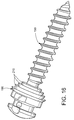
- FIG. 7 is a side elevational view of a mesial anchor screw of the present invention.
- FIG. 8 is a side elevational view in section of the mesial anchor screw as shown in FIG. 7 ;
- FIG. 9 is a perspective view of the mesial anchor screw shown in FIG. 7 ;
- FIG. 10 is a side elevational view of a zygomatic anchor screw of the present invention.
- FIG. 11 is a side elevational view in section of the zygomatic anchor screw as shown in FIG. 10 ;
- FIG. 12 is a perspective view of the zygomatic anchor screw shown in FIG. 10 ;
- FIG. 13 is a perspective view of a first embodiment of an anchor screw having a flexible and resilient washer in accordance with the present invention
- FIG. 14 is a perspective view of the anchor screw shown in FIG. 13 without the washer;
- FIG. 15 is a perspective view of a second embodiment of an anchor screw having a flexible and resilient washer.
- FIG. 16 is a perspective view of the anchor screw shown in FIG. 15 without the washer.
- anchor screws of different constructions are provided for different areas of the mouth to anchor orthodontic appliances or the like.
- the anchor screws are constructed to insure adequate bone contact and retention and lateral support in each area of the mouth to prevent movement or failure of the screws when subjected to lateral forces or the like.
- FIGS. 1-3 illustrate an anchor screw 10 for the incisal area of the mouth.
- the screw 10 comprises a threaded portion 12 that merges outwardly with an enlarged washer portion 14 that is connected to a narrower neck portion 16 that is in turn connected to a head portion 18 of larger size than the neck portion and of smaller size than the washer portion.
- the threaded portion 12 is of a size such that it can be placed between the roots of the lower anterior teeth, and the washer portion 14 is of sufficient width or diameter to provide adequate lateral support for the threaded portion 12 when the interior surface of the washer portion 14 engages the adjacent exterior cortical bone surface upon installation of the screw 10 .
- the inner surface 20 of the washer portion 14 can be concave such that the outer edge portion thereof can cut through the gum tissue and engage the outer bone surface to provide lateral support for the threaded portion 12 when it is fully inserted in the adjacent bone area.
- the neck portion 16 is provided with a bore 22 therethrough and the head portion 18 is provided with recesses 24 aligned with the outer ends of the bore 22 such that a ligature (not shown) or the like can be passed through the bore 22 and outwardly through the recesses 24 through a cannulated driver (not shown) or the like for rotating and installing the screw in the desired position in the incisal area.
- a ligature (not shown) or the like can be passed through the bore 22 and outwardly through the recesses 24 through a cannulated driver (not shown) or the like for rotating and installing the screw in the desired position in the incisal area.
- a ligature not shown
- a cannulated driver not shown
- the threaded portion 12 may have a 1.5 mm thread diameter and an 8.0 mm thread length.
- the washer portion 14 may be approximately 1 mm in thickness or longitudinal length.
- FIGS. 4 , 5 and 6 illustrate an anchor screw 30 for the palatal area of the mouth which comprises an inner threaded portion 32 and an intermediate threaded portion 34 of a size larger than the inner threaded portion 32 .
- the anchor screw 30 has an enlarged washer portion 36 having threads 38 on the exterior surface thereof.
- the washer portion 36 merges outwardly with a neck portion 40 and a head portion 42 of a construction similar to that of the neck portion 16 and head portion 18 of the incisal anchor screw 10 shown in FIGS. 1-3 and thus are not described in detail herein.
- the outer end 44 of the washer portion 36 adjacent the neck portion 40 is in the form of an angled nut such that it can be engaged by a cannulated driver (not shown) or the like for rotating and installing the anchor screw 30 in a desired position in the mouth.
- the inner smaller threaded portion 32 penetrates the bone first and the larger intermediate threaded portion 34 then engages the cortical bone to anchor the screw therein.
- the threads 38 on the washer portion 36 cut through the surrounding gum tissue to facilitate the engagement of the inner surface of the washer portion 36 with the outer surface of the cortical bone to provide adequate lateral support for the threaded portions 32 and 34 installed in the bone.
- the inner portion 32 may have a 2.0 mm starter thread and the intermediate portion 34 may have a 2.5 mm final thread.
- the thread length may be 6.5 mm.
- the threaded head portion 36 may have a 4 mm outer diameter and may be 3 mm in thickness.
- FIGS. 7 , 8 and 9 illustrate an anchor screw 50 for placement mesial to either the upper or lower molars.
- the anchor screw 50 comprises an inner threaded portion 52 , a larger intermediate threaded portion 54 and an enlarged threaded washer portion 56 that are similar in construction to the threaded portions 32 , 34 and the washer portion 36 of the palatal anchor screw 30 shown in FIGS. 4-6 .
- the threaded washer portion 56 is of less thickness than the washer portion 36 of the palatal anchor screw 30 for the reason that the gum tissue in the area mesial to the upper or lower molars is of less thickness than that in the palatal area.
- the anchor screw 50 comprises an angled nut portion 58 , a neck portion 60 and a head portion 62 similar to the nut portion 44 , neck portion 40 and head portion 42 , respectively, of the palatal anchor screw 30 and thus are not described in detail herein.
- the mesial anchor screw 50 may have a 1.5 mm inner threaded portion 52 , a 2.0 mm intermediate threaded portion 54 , a thread length of approximately 6.5 mm, and a washer portion 56 of approximately 4 mm outer diameter.
- FIGS. 11-13 illustrate an anchor screw 70 for use in the zygomatic area in the mouth and, more specifically, for placement in the zygomatic process of the maxillary bone.
- the anchor screw 70 comprises an inner threaded portion 72 that is connected at its outer end with an enlarged and elongated washer portion 74 .
- the outer end of the washer portion 74 merges with an angled nut portion 76 that is connected to a neck portion 78 that is in turn connected to an outer head portion 80 .
- the nut portion 76 , neck portion 78 and head portion 80 are similar to the nut portion 14 , neck portion 16 and head portion 18 respectively, of the incisal anchor screw 10 and thus are not described in detail herein.
- the inner surface 82 of the washer portion 74 may be concave to provide a sharp outer edge portion 84 that cuts through the gum tissue and engages a cortical bone for lateral support when the threaded portion 72 is installed in the bone in the zygomatic area.
- the washer portion 74 is elongated and is of a greater length than the washer portion 14 of the incisal anchor screw 10 for the reason that the gum tissue in the zygomatic area is unattached tissue of a greater thickness. In this manner, tissue is prevented from growing over the head portion 80 of the anchor screw 70 to insure that the neck portion 78 and head portion 80 of the anchor screw 70 are fully exposed when the anchor screw 70 is installed in the bone in the zygomatic area.
- the threaded portion 72 of the zygomatic anchor screw 70 may have a starter thread of approximately 2.0 mm and a final thread of approximately 3.0 mm, with a thread length of approximately 5 mm.
- the inner end of the washer portion 74 may have an outer diameter of approximately 4 mm, and the washer portion 74 may have a thickness of approximately 5 mm. with a concave outer diameter to facilitate the handling and use thereof.
- FIGS. 13 and 14 illustrate a further embodiment of the present invention wherein anchor screw 90 of any suitable construction or configuration is provided with a flexible and resilient washer 92 disposed at the outer end of the threaded portion 94 and adjacent to the inner surface of the washer portion 96 of the anchor screw 90 .
- the anchor screw 90 may have an outer angled nut portion 98 , a neck portion 100 and a head portion 102 similar to the same components of the anchor screws 10 , 30 , 50 and 70 disclosed herein.
- the inner surface 104 of the washer 92 is concave to provide a relatively sharp outer edge 106 for engagement with the outer bone surface when the anchor screw 90 is installed in the bone in a selected area of the mouth.
- the outer end of the washer 92 is provided with a concave recess 108 of a size and shape complementary to that of the inner end of the washer portion 96 of the anchor screw 90 so that it can be seated therein.
- the inner surface of the washer portion 96 is generally convex and may be formed of a plurality of concentric sharp edge portions 110 .
- the purpose of the flexible and resilient washer 92 is to engage the outer bone surface for lateral support of the anchor screw 90 when it is installed at various angles to the adjacent bone surface.
- the sharp concentric portions 110 at the inner end of the washer portion 96 of the anchor screw 90 served to engage the adjacent concave surface 108 of the flexible and resilient washer 92 to hold the washer in place firmly against the outer bone surface for proper lateral support of the anchor screw 90 .
- the anchor screw 190 and washer 192 shown in FIGS. 15 and 16 are very similar to the anchor screw 90 and washer 92 shown in FIGS. 13 and 14 .
- the anchor screw 190 differs from the anchor screw 90 in that the inner surface of its washer portion 198 is formed of larger concentric sharp edge portions 210 that fit and anchor within the adjacent concave recess 208 in the washer 192 .
- the washers 92 and 192 may be formed of any suitable flexible and resilient material, such as plastic and, more particularly, ultra high molecular weight polyethylene, Teflon, polyurethane or Peek.
- the anchor screws disclosed herein may be formed of any suitable material of sufficient strength and safety for the mouth area, e.g., a metal such as titanium, cobalt chromium or stainless steel.
Abstract
Description
-
- 1. For the incisal area of the mouth, an anchor screw having one thread size is used and is of a length and diameter to be placed between the roots of the lower anterior teeth.
- 2. For the palatal mouth area, the anchor screw has two thread sizes such that the initial or inner thread portion penetrates the bone first and an intermediate portion of a larger thread size anchors in the cortical bone. At the inner end of the washer portion, a large diameter threaded portion is provided for cutting through the gingival tissue of the palate such that the inner surface of the washer portion can seat against the bone to provide adequate lateral support.
- 3. The anchor screw for the zygomatic process of the maxillary bone is provided with a single thread size and has a washer portion of increased longitudinal size or height such that its outer portion extends beyond the gum tissue in this area.
- 4. The anchor device to be placed mesial to either the upper or lower molars has a construction similar to that of the palatal anchor device except that the longitudinal length or height of the head portion is not as large as that of the palatal anchor screw for the reason that the tissue in these areas is of less thickness than in the palatal area.
Claims (4)
Priority Applications (7)
| Application Number | Priority Date | Filing Date | Title |
|---|---|---|---|
| US11/508,909 US7806686B2 (en) | 2006-08-24 | 2006-08-24 | Anchor apparatus and method for orthodontic appliances |
| KR1020070022052A KR20080019153A (en) | 2006-08-24 | 2007-03-06 | Anchor apparatus and method for orthodontic appliances |
| CA002661622A CA2661622A1 (en) | 2006-08-24 | 2007-07-31 | Anchor apparatus and method for orthodontic appliances |
| PCT/US2007/017068 WO2008024179A2 (en) | 2006-08-24 | 2007-07-31 | Anchor apparatus and method for orthodontic appliances |
| EP07810924A EP2056731A4 (en) | 2006-08-24 | 2007-07-31 | Anchor apparatus and method for orthodontic appliances |
| AU2007288394A AU2007288394A1 (en) | 2006-08-24 | 2007-07-31 | Anchor apparatus and method for orthodontic appliances |
| US12/923,678 US20110033813A1 (en) | 2006-08-24 | 2010-10-04 | Anchor apparatus and method for orthodontic appliances |
Applications Claiming Priority (1)
| Application Number | Priority Date | Filing Date | Title |
|---|---|---|---|
| US11/508,909 US7806686B2 (en) | 2006-08-24 | 2006-08-24 | Anchor apparatus and method for orthodontic appliances |
Related Child Applications (1)
| Application Number | Title | Priority Date | Filing Date |
|---|---|---|---|
| US12/923,678 Division US20110033813A1 (en) | 2006-08-24 | 2010-10-04 | Anchor apparatus and method for orthodontic appliances |
Publications (2)
| Publication Number | Publication Date |
|---|---|
| US20080050691A1 US20080050691A1 (en) | 2008-02-28 |
| US7806686B2 true US7806686B2 (en) | 2010-10-05 |
Family
ID=39107272
Family Applications (2)
| Application Number | Title | Priority Date | Filing Date |
|---|---|---|---|
| US11/508,909 Expired - Fee Related US7806686B2 (en) | 2006-08-24 | 2006-08-24 | Anchor apparatus and method for orthodontic appliances |
| US12/923,678 Abandoned US20110033813A1 (en) | 2006-08-24 | 2010-10-04 | Anchor apparatus and method for orthodontic appliances |
Family Applications After (1)
| Application Number | Title | Priority Date | Filing Date |
|---|---|---|---|
| US12/923,678 Abandoned US20110033813A1 (en) | 2006-08-24 | 2010-10-04 | Anchor apparatus and method for orthodontic appliances |
Country Status (6)
| Country | Link |
|---|---|
| US (2) | US7806686B2 (en) |
| EP (1) | EP2056731A4 (en) |
| KR (1) | KR20080019153A (en) |
| AU (1) | AU2007288394A1 (en) |
| CA (1) | CA2661622A1 (en) |
| WO (1) | WO2008024179A2 (en) |
Cited By (2)
| Publication number | Priority date | Publication date | Assignee | Title |
|---|---|---|---|---|
| US20130130200A1 (en) * | 2011-10-21 | 2013-05-23 | Milan Djordjevic | Flatbed Dental Implant |
| US20220370175A1 (en) * | 2021-05-20 | 2022-11-24 | Ho Fung KWAN | Dental implant able to enhance stability |
Families Citing this family (25)
| Publication number | Priority date | Publication date | Assignee | Title |
|---|---|---|---|---|
| US8118850B2 (en) | 2007-12-10 | 2012-02-21 | Marcus Jeffrey R | Intermaxillary fixation device and method of using same |
| EP2237735B1 (en) | 2007-12-31 | 2015-10-07 | Jeffrey R. Marcus | Intermaxillary fixation device |
| US8083521B2 (en) * | 2008-04-30 | 2011-12-27 | Toads Llc | Anchor apparatus for orthodontic appliances |
| JP4489133B2 (en) * | 2008-09-10 | 2010-06-23 | 株式会社東芝 | Printed wiring boards, electronic devices |
| JP4421663B1 (en) * | 2008-09-10 | 2010-02-24 | 株式会社東芝 | Printed wiring boards, electronic devices |
| KR20100031917A (en) * | 2008-09-16 | 2010-03-25 | 주식회사 이노바이오써지 | Positonning device for dental implant |
| WO2010032898A1 (en) * | 2008-09-16 | 2010-03-25 | Miratech | Dental implant |
| US8454363B2 (en) | 2008-11-06 | 2013-06-04 | William B. Worthington | Dental implant system |
| IT1400805B1 (en) * | 2010-07-02 | 2013-07-02 | Vigolo | ORTHODONTIC ANCHOR SCREW AND PROCEDURE FOR ITS REALIZATION |
| US9011144B2 (en) * | 2011-09-14 | 2015-04-21 | Roberto Carrillo Fuentevilla | Palatal t-bar |
| RU2477495C1 (en) * | 2011-10-25 | 2013-03-10 | Открытое акционерное общество "Корпорация космических систем специального назначения "Комета" | Method of calibrating radar station from effective radar cross-section value during dynamic measurement of effective radar cross-section of analysed objects |
| RU2477496C1 (en) * | 2011-10-25 | 2013-03-10 | Открытое акционерное общество "Корпорация космических систем специального назначения "Комета" | Method of calibrating radar station operating on circularly polarised waves with parallel reception of reflected signals based on value of effective radar cross-section during dynamic measurement of effective radar cross-section of ballistic and space objects |
| DE102013001933B4 (en) * | 2012-09-07 | 2017-09-14 | Human Tech Germany Gmbh | Bone screw for fixation of a bone screw rod system |
| US10378131B2 (en) * | 2013-08-08 | 2019-08-13 | EverestMedica LLC | Surgical braids |
| US9610077B2 (en) | 2013-08-08 | 2017-04-04 | EverestMedica LLC | Round-flat-round surgical braids |
| US11447901B2 (en) | 2013-04-12 | 2022-09-20 | EverestMedica LLC | Method of making a surgical braid |
| DE102013111842A1 (en) | 2013-10-28 | 2015-04-30 | Universität Rostock | Mini screw for orthopedic reconstructions |
| USD744106S1 (en) * | 2014-11-12 | 2015-11-24 | Orthoarm, Inc. | Orthodontic anchorage device |
| USD744105S1 (en) * | 2014-10-27 | 2015-11-24 | Orthoarm, Inc. | Orthodontic anchorage device |
| USD773926S1 (en) * | 2015-06-01 | 2016-12-13 | Spinal Generations, Llc | Screw |
| WO2017083644A1 (en) * | 2015-11-11 | 2017-05-18 | Marcus Jeffrey R | Intermaxillary fixation device and method of using same |
| JP6664937B2 (en) * | 2015-11-19 | 2020-03-13 | 国立大学法人 鹿児島大学 | Anchor screw device with dome-shaped coupling force maintenance tool |
| JP6589616B2 (en) * | 2015-12-11 | 2019-10-16 | 国立大学法人 鹿児島大学 | Maxilla enlargement device |
| BR202018003759U2 (en) * | 2018-02-26 | 2019-09-10 | Nagassawa Eduardo | constructive arrangement introduced in mini-implant for orthodontic anchorage |
| KR102179725B1 (en) * | 2018-11-20 | 2020-11-17 | 주식회사 덴티스 | screw for orthodontic treatment |
Citations (50)
| Publication number | Priority date | Publication date | Assignee | Title |
|---|---|---|---|---|
| US951437A (en) * | 1909-04-14 | 1910-03-08 | Edward A Gehrke | Tap-screw for plugging leaks. |
| US2226491A (en) * | 1939-08-10 | 1940-12-24 | Continental Screw Company | Self-locking screw, bolt, nut, or the like |
| US2490364A (en) * | 1948-02-27 | 1949-12-06 | Herman H Livingston | Bone pin |
| US2959204A (en) * | 1958-06-18 | 1960-11-08 | Burdsall & Ward Co | Threaded fastener with biting teeth and bearing platform |
| US3469490A (en) * | 1967-10-18 | 1969-09-30 | Loctite Corp | Self-sealing mechanical fastener |
| US4350465A (en) * | 1980-04-28 | 1982-09-21 | Industrial Fasteners Corp. | Spider washer head screw |
| US4468200A (en) | 1982-11-12 | 1984-08-28 | Feldmuhle Aktiengesellschaft | Helical mandibular implant |
| US4812095A (en) * | 1987-02-24 | 1989-03-14 | Emhart Industries, Inc. | Threaded fastener |
| US4988351A (en) * | 1989-01-06 | 1991-01-29 | Concept, Inc. | Washer for use with cancellous screw for attaching soft tissue to bone |
| US5263996A (en) | 1990-10-18 | 1993-11-23 | Filhol Stuart J | Dental pin |
| US5433719A (en) * | 1993-03-25 | 1995-07-18 | Pennig; Dietmar | Fixation pin for small-bone fragments |
| US5453010A (en) | 1994-03-11 | 1995-09-26 | Dental Logics, Inc. | Dental post with internal retention means |
| US5507643A (en) | 1994-03-11 | 1996-04-16 | Dental Logics, Inc. | Kit, tool and method of use for securing a dental restoration on a prepared tooth stub |
| US5522843A (en) * | 1994-02-23 | 1996-06-04 | Orthopaedic Biosystems Limited, Inc. | Apparatus for attaching soft tissue to bone |
| US5564924A (en) | 1995-02-21 | 1996-10-15 | Kwan; Norman H. | Hexagonal abutment implant system |
| US5697779A (en) | 1995-06-07 | 1997-12-16 | Ormco Corporation | Temporary implant for use as an anchor in the mouth |
| US5725345A (en) * | 1994-09-26 | 1998-03-10 | Zhov; Peng | Tire repair screw with sealing material |
| US5746560A (en) * | 1997-03-31 | 1998-05-05 | Illinois Tool Works Inc. | Fastener having torque-absorbing ribs |
| US5814070A (en) * | 1996-02-20 | 1998-09-29 | Howmedica Inc. | Suture anchor and driver |
| US5871504A (en) | 1997-10-21 | 1999-02-16 | Eaton; Katulle Koco | Anchor assembly and method for securing ligaments to bone |
| US5925047A (en) * | 1998-10-19 | 1999-07-20 | Third Millennium Engineering, Llc | Coupled rod, anterior vertebral body screw, and staple assembly |
| US6015410A (en) * | 1997-12-23 | 2000-01-18 | Bionx Implants Oy | Bioabsorbable surgical implants for endoscopic soft tissue suspension procedure |
| US6027523A (en) | 1997-10-06 | 2000-02-22 | Arthrex, Inc. | Suture anchor with attached disk |
| US6139565A (en) | 1993-06-23 | 2000-10-31 | Kevin R. Stone | Suture anchor assembly |
| US6290499B1 (en) | 1994-11-08 | 2001-09-18 | Implant Innovations, Inc. | Transfer-type impression coping |
| US6312259B1 (en) | 1999-12-17 | 2001-11-06 | Nobel Biocare Ab | Bone implant |
| US20020182560A1 (en) * | 2000-07-12 | 2002-12-05 | Young-Chel Park | Implant for teeth orthodontics |
| US20030105465A1 (en) * | 2001-11-13 | 2003-06-05 | Reinhold Schmieding | Implant screw and washer assembly and method of fixation |
| US6575976B2 (en) * | 2000-06-12 | 2003-06-10 | Arthrex, Inc. | Expandable tissue anchor |
| US6575742B2 (en) * | 2001-03-07 | 2003-06-10 | Hee Moon Kyung | Osteogenic support device for orthodontic treatment |
| US6648892B2 (en) * | 1997-06-02 | 2003-11-18 | Jeannette Martello | Soft tissue securing anchor |
| US6648893B2 (en) * | 2000-10-27 | 2003-11-18 | Blackstone Medical, Inc. | Facet fixation devices |
| US6669473B1 (en) * | 1999-11-26 | 2003-12-30 | Nicos Sas Di De Toni Nicoletta & C. | Anchor screw for orthodontic treatments |
| US6689137B2 (en) * | 2001-10-15 | 2004-02-10 | Gary Jack Reed | Orthopedic fastener and method |
| US20040059336A1 (en) * | 2002-09-25 | 2004-03-25 | Giuseppe Lombardo | Soft tissue anchor |
| US20040157187A1 (en) * | 2003-02-07 | 2004-08-12 | Cheng-Yi Lin | Screw device for orthodontic treatment |
| US20040166460A1 (en) * | 2003-02-25 | 2004-08-26 | John Devincenzo | Orthodontic anchor |
| US6800078B2 (en) * | 2001-11-07 | 2004-10-05 | Lock-N-Stitch, Inc. | Orthopedic stabilization device and method |
| US20050059972A1 (en) | 2003-09-16 | 2005-03-17 | Spineco, Inc., An Ohio Corporation | Bone anchor prosthesis and system |
| US20050095550A1 (en) * | 2002-06-27 | 2005-05-05 | Jung-Moon Kim | Orthodontic implant |
| US20050100854A1 (en) * | 2003-11-07 | 2005-05-12 | Hee Moon Kyung | Osteogenic support device for orthodontic treatment |
| US20050130093A1 (en) * | 2003-12-11 | 2005-06-16 | Cheng-Yi Lin | Screw device for orthodontic treatment |
| US20050227197A1 (en) * | 2002-08-05 | 2005-10-13 | Cheng-Yi Lin | Screw device for orthodontic treatment |
| US20060004365A1 (en) | 1996-08-05 | 2006-01-05 | Arthrex, Inc. | Corkscrew suture anchor |
| US6997711B2 (en) | 2002-12-23 | 2006-02-14 | Robert Jeffrey Miller | Dental implant |
| US20060046229A1 (en) | 2004-08-26 | 2006-03-02 | Teich Thomas J | Dental implant |
| US20060100629A1 (en) * | 2004-11-09 | 2006-05-11 | Lee James M | Method and apparatus for repair of torn rotator cuff tendons |
| US20060199138A1 (en) * | 2003-11-25 | 2006-09-07 | Leonardo Corti | Orthodontic microscrew |
| US20070083206A1 (en) * | 2005-09-21 | 2007-04-12 | Microware Precision Co., Ltd. | Self drilling and tapping bone screw |
| US20070122764A1 (en) * | 2005-11-28 | 2007-05-31 | Ace Surgical Supply Co., Inc. | Orthodontic bone screw |
Family Cites Families (9)
| Publication number | Priority date | Publication date | Assignee | Title |
|---|---|---|---|---|
| JPS4825541Y1 (en) * | 1969-03-07 | 1973-07-25 | ||
| US3746560A (en) * | 1971-03-25 | 1973-07-17 | Great Lakes Carbon Corp | Oxidized carbon fibers |
| IT1237496B (en) * | 1989-10-26 | 1993-06-08 | Giuseppe Vrespa | SCREW DEVICE FOR ANCHORING BONE PROSTHESES, METHOD FOR THE APPLICATION OF SUCH DEVICE AND RELATED EQUIPMENT |
| US5489210A (en) * | 1994-05-13 | 1996-02-06 | Hanosh; Frederick N. | Expanding dental implant and method for its use |
| BR9707531A (en) * | 1996-02-16 | 1999-07-27 | Smith & Nephew Inc | graft anchor |
| US6827574B2 (en) * | 2001-04-12 | 2004-12-07 | Kevin L. Payton | Skeletal transmucosal orthodontic plate and method |
| JP3928173B2 (en) * | 2003-12-26 | 2007-06-13 | 堀田 康記 | Orthodontic support |
| US7559764B2 (en) * | 2004-01-06 | 2009-07-14 | John Devincenzo | Orthodontic bone anchor |
| FR2865373B1 (en) * | 2004-01-27 | 2006-03-03 | Medicrea International | MATERIAL OF VERTEBRAL OSTEOSYNTHESIS |
-
2006
- 2006-08-24 US US11/508,909 patent/US7806686B2/en not_active Expired - Fee Related
-
2007
- 2007-03-06 KR KR1020070022052A patent/KR20080019153A/en not_active Application Discontinuation
- 2007-07-31 WO PCT/US2007/017068 patent/WO2008024179A2/en active Application Filing
- 2007-07-31 EP EP07810924A patent/EP2056731A4/en not_active Withdrawn
- 2007-07-31 CA CA002661622A patent/CA2661622A1/en not_active Abandoned
- 2007-07-31 AU AU2007288394A patent/AU2007288394A1/en not_active Abandoned
-
2010
- 2010-10-04 US US12/923,678 patent/US20110033813A1/en not_active Abandoned
Patent Citations (51)
| Publication number | Priority date | Publication date | Assignee | Title |
|---|---|---|---|---|
| US951437A (en) * | 1909-04-14 | 1910-03-08 | Edward A Gehrke | Tap-screw for plugging leaks. |
| US2226491A (en) * | 1939-08-10 | 1940-12-24 | Continental Screw Company | Self-locking screw, bolt, nut, or the like |
| US2490364A (en) * | 1948-02-27 | 1949-12-06 | Herman H Livingston | Bone pin |
| US2959204A (en) * | 1958-06-18 | 1960-11-08 | Burdsall & Ward Co | Threaded fastener with biting teeth and bearing platform |
| US3469490A (en) * | 1967-10-18 | 1969-09-30 | Loctite Corp | Self-sealing mechanical fastener |
| US4350465A (en) * | 1980-04-28 | 1982-09-21 | Industrial Fasteners Corp. | Spider washer head screw |
| US4468200A (en) | 1982-11-12 | 1984-08-28 | Feldmuhle Aktiengesellschaft | Helical mandibular implant |
| US4812095A (en) * | 1987-02-24 | 1989-03-14 | Emhart Industries, Inc. | Threaded fastener |
| US4988351A (en) * | 1989-01-06 | 1991-01-29 | Concept, Inc. | Washer for use with cancellous screw for attaching soft tissue to bone |
| US5263996A (en) | 1990-10-18 | 1993-11-23 | Filhol Stuart J | Dental pin |
| US5433719A (en) * | 1993-03-25 | 1995-07-18 | Pennig; Dietmar | Fixation pin for small-bone fragments |
| US6139565A (en) | 1993-06-23 | 2000-10-31 | Kevin R. Stone | Suture anchor assembly |
| US5522843A (en) * | 1994-02-23 | 1996-06-04 | Orthopaedic Biosystems Limited, Inc. | Apparatus for attaching soft tissue to bone |
| US5453010A (en) | 1994-03-11 | 1995-09-26 | Dental Logics, Inc. | Dental post with internal retention means |
| US5507643A (en) | 1994-03-11 | 1996-04-16 | Dental Logics, Inc. | Kit, tool and method of use for securing a dental restoration on a prepared tooth stub |
| US5725345A (en) * | 1994-09-26 | 1998-03-10 | Zhov; Peng | Tire repair screw with sealing material |
| US6290499B1 (en) | 1994-11-08 | 2001-09-18 | Implant Innovations, Inc. | Transfer-type impression coping |
| US5564924A (en) | 1995-02-21 | 1996-10-15 | Kwan; Norman H. | Hexagonal abutment implant system |
| US5697779A (en) | 1995-06-07 | 1997-12-16 | Ormco Corporation | Temporary implant for use as an anchor in the mouth |
| US5814070A (en) * | 1996-02-20 | 1998-09-29 | Howmedica Inc. | Suture anchor and driver |
| US20060004365A1 (en) | 1996-08-05 | 2006-01-05 | Arthrex, Inc. | Corkscrew suture anchor |
| US5746560A (en) * | 1997-03-31 | 1998-05-05 | Illinois Tool Works Inc. | Fastener having torque-absorbing ribs |
| US6648892B2 (en) * | 1997-06-02 | 2003-11-18 | Jeannette Martello | Soft tissue securing anchor |
| US6027523A (en) | 1997-10-06 | 2000-02-22 | Arthrex, Inc. | Suture anchor with attached disk |
| US5871504A (en) | 1997-10-21 | 1999-02-16 | Eaton; Katulle Koco | Anchor assembly and method for securing ligaments to bone |
| US6015410A (en) * | 1997-12-23 | 2000-01-18 | Bionx Implants Oy | Bioabsorbable surgical implants for endoscopic soft tissue suspension procedure |
| US5925047A (en) * | 1998-10-19 | 1999-07-20 | Third Millennium Engineering, Llc | Coupled rod, anterior vertebral body screw, and staple assembly |
| US6669473B1 (en) * | 1999-11-26 | 2003-12-30 | Nicos Sas Di De Toni Nicoletta & C. | Anchor screw for orthodontic treatments |
| US6312259B1 (en) | 1999-12-17 | 2001-11-06 | Nobel Biocare Ab | Bone implant |
| US6575976B2 (en) * | 2000-06-12 | 2003-06-10 | Arthrex, Inc. | Expandable tissue anchor |
| US20020182560A1 (en) * | 2000-07-12 | 2002-12-05 | Young-Chel Park | Implant for teeth orthodontics |
| US6648893B2 (en) * | 2000-10-27 | 2003-11-18 | Blackstone Medical, Inc. | Facet fixation devices |
| US6575742B2 (en) * | 2001-03-07 | 2003-06-10 | Hee Moon Kyung | Osteogenic support device for orthodontic treatment |
| US6689137B2 (en) * | 2001-10-15 | 2004-02-10 | Gary Jack Reed | Orthopedic fastener and method |
| US6800078B2 (en) * | 2001-11-07 | 2004-10-05 | Lock-N-Stitch, Inc. | Orthopedic stabilization device and method |
| US20030105465A1 (en) * | 2001-11-13 | 2003-06-05 | Reinhold Schmieding | Implant screw and washer assembly and method of fixation |
| US20050095550A1 (en) * | 2002-06-27 | 2005-05-05 | Jung-Moon Kim | Orthodontic implant |
| US7101177B2 (en) * | 2002-08-05 | 2006-09-05 | Cheng-Yi Lin | Screw device for orthodontic treatment |
| US20050227197A1 (en) * | 2002-08-05 | 2005-10-13 | Cheng-Yi Lin | Screw device for orthodontic treatment |
| US20040059336A1 (en) * | 2002-09-25 | 2004-03-25 | Giuseppe Lombardo | Soft tissue anchor |
| US6997711B2 (en) | 2002-12-23 | 2006-02-14 | Robert Jeffrey Miller | Dental implant |
| US20040157187A1 (en) * | 2003-02-07 | 2004-08-12 | Cheng-Yi Lin | Screw device for orthodontic treatment |
| US20040166460A1 (en) * | 2003-02-25 | 2004-08-26 | John Devincenzo | Orthodontic anchor |
| US20050059972A1 (en) | 2003-09-16 | 2005-03-17 | Spineco, Inc., An Ohio Corporation | Bone anchor prosthesis and system |
| US20050100854A1 (en) * | 2003-11-07 | 2005-05-12 | Hee Moon Kyung | Osteogenic support device for orthodontic treatment |
| US20060199138A1 (en) * | 2003-11-25 | 2006-09-07 | Leonardo Corti | Orthodontic microscrew |
| US20050130093A1 (en) * | 2003-12-11 | 2005-06-16 | Cheng-Yi Lin | Screw device for orthodontic treatment |
| US20060046229A1 (en) | 2004-08-26 | 2006-03-02 | Teich Thomas J | Dental implant |
| US20060100629A1 (en) * | 2004-11-09 | 2006-05-11 | Lee James M | Method and apparatus for repair of torn rotator cuff tendons |
| US20070083206A1 (en) * | 2005-09-21 | 2007-04-12 | Microware Precision Co., Ltd. | Self drilling and tapping bone screw |
| US20070122764A1 (en) * | 2005-11-28 | 2007-05-31 | Ace Surgical Supply Co., Inc. | Orthodontic bone screw |
Cited By (2)
| Publication number | Priority date | Publication date | Assignee | Title |
|---|---|---|---|---|
| US20130130200A1 (en) * | 2011-10-21 | 2013-05-23 | Milan Djordjevic | Flatbed Dental Implant |
| US20220370175A1 (en) * | 2021-05-20 | 2022-11-24 | Ho Fung KWAN | Dental implant able to enhance stability |
Also Published As
| Publication number | Publication date |
|---|---|
| US20080050691A1 (en) | 2008-02-28 |
| US20110033813A1 (en) | 2011-02-10 |
| WO2008024179A3 (en) | 2008-07-17 |
| EP2056731A4 (en) | 2011-06-29 |
| WO2008024179A2 (en) | 2008-02-28 |
| EP2056731A2 (en) | 2009-05-13 |
| KR20080019153A (en) | 2008-03-03 |
| CA2661622A1 (en) | 2008-02-28 |
| AU2007288394A1 (en) | 2008-02-28 |
Similar Documents
| Publication | Publication Date | Title |
|---|---|---|
| US7806686B2 (en) | Anchor apparatus and method for orthodontic appliances | |
| EP2713939B1 (en) | Dental implant | |
| US10441387B2 (en) | Abutment system and dental methods | |
| US20070087301A1 (en) | Archwire assembly with stops | |
| US8814570B2 (en) | Dental implant | |
| WO2014088116A1 (en) | Fastening force maintaining device for screw, and screw equipped with fastening force maintaining device | |
| JPH0329647A (en) | Inter-teeth fixation instrument | |
| KR100807150B1 (en) | Implant for overdenture | |
| US10398534B2 (en) | One-part tooth implant, device for bending an implant, and method for bending an implant | |
| KR101551381B1 (en) | Anchorage for orthodontic treatment or maxillofacial surgery | |
| US6379154B2 (en) | Subperiosteal bone anchor | |
| EP0988836B1 (en) | Anchoring device for orthodontic correction treatment instruments | |
| US8251698B2 (en) | Orthodontic implant | |
| US20180132978A1 (en) | Bony bracket screw | |
| WO2012066524A1 (en) | Set of dental implant aligning tools | |
| KR101210671B1 (en) | Dental Implant | |
| KR100602798B1 (en) | Fixing device for orthodontic apparatus | |
| KR100602799B1 (en) | Fixing device for orthodontic apparatus | |
| KR101479598B1 (en) | Appliance for Protraction of maxillary bone | |
| CA1259866A (en) | Interdental immobilization device | |
| KR200459306Y1 (en) | Screw for Anchor of Orthodontic Treatment | |
| KR20120126139A (en) | Implant Fixture | |
| KR100931645B1 (en) | Othodontic screw | |
| WO2005074832A1 (en) | Provisional implant | |
| KR100727095B1 (en) | implant and fixing device for orthodontic apparatus utilizing the same |
Legal Events
| Date | Code | Title | Description |
|---|---|---|---|
| AS | Assignment |
Owner name: TOADS LLC, KENTUCKY Free format text: ASSIGNMENT OF ASSIGNORS INTEREST;ASSIGNORS:BAUGHMAN, DAVID;FISHER, JACK;REEL/FRAME:018215/0545;SIGNING DATES FROM 20060731 TO 20060805 Owner name: TOADS LLC, KENTUCKY Free format text: ASSIGNMENT OF ASSIGNORS INTEREST;ASSIGNORS:BAUGHMAN, DAVID;FISHER, JACK;SIGNING DATES FROM 20060731 TO 20060805;REEL/FRAME:018215/0545 |
|
| FPAY | Fee payment |
Year of fee payment: 4 |
|
| FEPP | Fee payment procedure |
Free format text: MAINTENANCE FEE REMINDER MAILED (ORIGINAL EVENT CODE: REM.) |
|
| LAPS | Lapse for failure to pay maintenance fees |
Free format text: PATENT EXPIRED FOR FAILURE TO PAY MAINTENANCE FEES (ORIGINAL EVENT CODE: EXP.); ENTITY STATUS OF PATENT OWNER: SMALL ENTITY |
|
| STCH | Information on status: patent discontinuation |
Free format text: PATENT EXPIRED DUE TO NONPAYMENT OF MAINTENANCE FEES UNDER 37 CFR 1.362 |
|
| FP | Lapsed due to failure to pay maintenance fee |
Effective date: 20181005 |