US7805902B2 - Fastener for grooved or slotted decking members - Google Patents
Fastener for grooved or slotted decking members Download PDFInfo
- Publication number
- US7805902B2 US7805902B2 US11/717,395 US71739507A US7805902B2 US 7805902 B2 US7805902 B2 US 7805902B2 US 71739507 A US71739507 A US 71739507A US 7805902 B2 US7805902 B2 US 7805902B2
- Authority
- US
- United States
- Prior art keywords
- body portion
- fastener
- decking
- coplanar
- connection
- Prior art date
- Legal status (The legal status is an assumption and is not a legal conclusion. Google has not performed a legal analysis and makes no representation as to the accuracy of the status listed.)
- Active, expires
Links
Images


Classifications
-
- E—FIXED CONSTRUCTIONS
- E04—BUILDING
- E04F—FINISHING WORK ON BUILDINGS, e.g. STAIRS, FLOORS
- E04F15/00—Flooring
- E04F15/02—Flooring or floor layers composed of a number of similar elements
- E04F15/10—Flooring or floor layers composed of a number of similar elements of other materials, e.g. fibrous or chipped materials, organic plastics, magnesite tiles, hardboard, or with a top layer of other materials
-
- E—FIXED CONSTRUCTIONS
- E04—BUILDING
- E04F—FINISHING WORK ON BUILDINGS, e.g. STAIRS, FLOORS
- E04F15/00—Flooring
- E04F15/02—Flooring or floor layers composed of a number of similar elements
-
- E—FIXED CONSTRUCTIONS
- E04—BUILDING
- E04F—FINISHING WORK ON BUILDINGS, e.g. STAIRS, FLOORS
- E04F15/00—Flooring
- E04F15/02—Flooring or floor layers composed of a number of similar elements
- E04F15/02044—Separate elements for fastening to an underlayer
- E04F2015/0205—Separate elements for fastening to an underlayer with load-supporting elongated furring elements between the flooring elements and the underlayer
- E04F2015/02066—Separate elements for fastening to an underlayer with load-supporting elongated furring elements between the flooring elements and the underlayer with additional fastening elements between furring elements and flooring elements
- E04F2015/02077—Separate elements for fastening to an underlayer with load-supporting elongated furring elements between the flooring elements and the underlayer with additional fastening elements between furring elements and flooring elements the additional fastening elements located in-between two adjacent flooring elements
- E04F2015/02094—Engaging side grooves running along the whole length of the flooring elements
-
- E—FIXED CONSTRUCTIONS
- E04—BUILDING
- E04F—FINISHING WORK ON BUILDINGS, e.g. STAIRS, FLOORS
- E04F2201/00—Joining sheets or plates or panels
- E04F2201/05—Separate connectors or inserts, e.g. pegs, pins, keys or strips
-
- E—FIXED CONSTRUCTIONS
- E04—BUILDING
- E04F—FINISHING WORK ON BUILDINGS, e.g. STAIRS, FLOORS
- E04F2201/00—Joining sheets or plates or panels
- E04F2201/05—Separate connectors or inserts, e.g. pegs, pins, keys or strips
- E04F2201/0517—U- or C-shaped brackets and clamps
Definitions
- the present invention relates to a deck fastener for securing decking members (e.g., boards or planks) together and to a supporting member and, more particularly, to a fastener for securing grooved or slotted decking members to an underlying support member.
- decking members e.g., boards or planks
- Composite deck boards or planks have become increasingly common as a replacement or alternative to traditional wood planks for outside decking or the like.
- Composite boards are made of a combination of materials usually including a polymer matrix material and one or more reinforcement materials such as wood fibers, with the polymer matrix surrounding and supporting the wood fiber reinforcement material.
- the reinforcement material provides strength, workability, and dimensional stability, while the polymer matrix material provides low-maintenance characteristics, durability (especially in terms of color longevity), and splinter-free wear.
- Composite deck boards may be fastened to underlying support members in the same manner as traditional wood planking, e.g., by driving a fastener down through the body of the deck board.
- composite boards are still subject to possible splitting.
- users prefer not to have fasteners protruding above the decking surface, as may be unsightly and/or create a hazard.
- conventional nails even if countersunk in the first instance, have a tendency to work themselves above the decking surface over time as the planking contracts and expands due to changing weather conditions.
- various systems have been proposed for securing deck boards together and to underlying supports in a “hidden” manner, e.g., the fasteners do not protrude above the decking surface.
- FIGS. 1A and 1B show a generally rectangular, generally planar, composite plank 10 having an elongate body 12 , first and second lateral ends 14 , 16 (e.g., the ends are perpendicular to a longitudinal axis 18 of the plank, which is the axis defined by the longest dimension of the plank), and left and right longitudinal sides 20 , 22 (e.g., the sides are parallel to the longitudinal axis 18 of the plank).
- Each side 20 , 22 has a longitudinal groove or slot 24 , 26 formed therein.
- a biscuit device such as shown in U.S. Pat. No.
- 6,402,415 to Eberle, III is used to hold adjacent planks together and to an underlying support.
- the connection between planks may not be as secure as desired.
- the planks may be subject to shifting or other movement.
- An embodiment of the present invention relates to a fastener for securing laterally adjacent, grooved decking members to an underlying support.
- Grooved decking member refers to an elongate board, plank, or other construction member having generally planar top and bottom surfaces, such as those suitable for use as the surface of a deck, where one or both of the side edges of the member are provided with longitudinal grooves or slots.
- the fastener includes a generally flat body portion with front and rear faces and top and bottom edges.
- a first connection wing is attached to the top edge of the body and extends outwardly from the rear face of the body in a first direction.
- a second connection wing is also attached to the top edge of the body, but extends generally outwardly from the front face of the body in a second, opposite direction.
- a flange is attached to the bottom edge of the body portion and extends outwardly from the rear face of the body in the general direction of the first connection wing.
- the flange and/or body portion include an opening for passage of a connector (e.g., screw) through the fastener.
- the connection wings are adapted in size and shape to engage laterally adjacent decking members when the wings are inserted into the longitudinal grooves formed in the sides of the decking members and the fastener is connected to a supporting member that supports and underlies the laterally adjacent decking members.
- a first decking member is held in place against the underlying support member.
- the fastener's second connection wing e.g., the connection wing opposite the flange
- the fastener's second connection wing is positioned in the decking member's longitudinal groove such that the connector opening is positioned proximate to the support member and the flange is facing away from the decking member.
- a screw or other connector is inserted through the opening and is secured in place down into the support member.
- several fasteners are deployed in this manner at even intervals along the length of the decking member.
- a second decking member is placed laterally against the first decking member by maneuvering its longitudinal side groove over the fastener's first connection wing.
- the second decking member lies against the support member, and is then moved towards the first decking member until it abuts the flange, which establishes a gap between the two decking members.
- the connection wings engage the decking members in the slots for securing the decking members against the support member, e.g., lip-like portions of the decking members, which lie below the grooves, are sandwiched between the connection wings and the underlying support, preventing the decking members from being substantially raised upwards.
- the flange is generally perpendicular to the rear face of the body portion.
- the first connection wing e.g., the wing positioned on the same side as the flange
- the second connection wing is longer than the second connection wing in a latter manner. This means that the first connection wing extends out from the body portion by a lateral distance greater than that of the second connection wing. (“Lateral distance” refers to the distance between the body portion and the farthest, distal edge of the wing, as measured normally/perpendicularly to the front or rear face of the body portion, as applicable.)
- connection wings are “bent” in shape, with each including first and second portions that are non-coplanar to one another.
- first non-coplanar portion is attached to the top edge of the body and lies generally perpendicular to the fastener body portion.
- the second non-coplanar portion which defines the distal end of the connection wing, is attached to an edge of the first portion opposite (and typically parallel to) the top edge of the body.
- the second portion is inclined at an angle with respect to the first portion for leveraged engagement of the connection wing with a decking member when inserted into a longitudinal groove thereof.
- a first grooved decking member is held in place against an underlying joist or other support member.
- the second, laterally shorter connection wing e.g., the connection wing on the opposite side of the body from the flange
- the fastener's connector opening is positioned proximate to the support member, and the flange faces away from the decking member.
- a connector is inserted through the connector opening and is secured in place down into the support member.
- the fastener body and flange are located on one side of the plane, and the angled or bent portions of the wings extend out past the opposite side of the plane.
- the angled or bent portions are angled from about 15° to about 75° with respect to the plane defined by the first connection wing portions.
- connection wings are generally rectangular and have generally rectangular distal ends.
- the distal ends may be provided with wedge-shaped prongs, e.g., positioned at the left and right corners of the distal end, for the connection wings to bite into the decking members inside the longitudinal grooves.
- FIGS. 1A and 1B are views of a grooved decking member
- FIGS. 2A-2D are perspective, front side elevation, left side elevation, and bottom plan views, respectively, of a fastener for grooved or slotted decking members, according to a first embodiment of the present invention
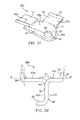
- FIGS. 3A and 3B are perspective and side elevation views, respectively, of a fastener according to an additional embodiment of the present invention.
- FIGS. 4A-4C and 5 A- 5 D are side elevation views showing the fasteners in use
- FIG. 6 is a perspective view of an alternative embodiment of the fastener shown in FIGS. 3A and 3B ;
- FIGS. 7A-7C are end side elevation, rear side elevation, and bottom plan views, respectively, of a fastener according to an additional embodiment of the present invention.
- FIGS. 8A and 8B are end side elevation and top plan views, respectively, of a fastener according to an additional, embodiment of the present invention.
- the present invention relates to a novel fastener device 30 a , 30 b for connecting (i) a first grooved or slotted board, plank, or other decking member 32 to an underlying joist or other support member 34 and (ii) a second grooved decking member 36 to the first decking member 32 in an adjacent or lateral manner.
- the fastener 30 a , 30 b is used, in effect, to connect two decking members to one another and both decking members to an underlying support 34 .
- the fastener 30 a , 30 b includes a thin, flat body portion 38 , two connection lips or “wings” 40 a , 40 b , and a main flange 42 .
- the wings 40 a , 40 b extend out from the top edge 44 of the body portion 38 in opposite directions.
- the first wing 40 a is attached along one side of the top edge 44 of the body 38 , and extends outwardly from the body in the direction of a rear face 45 a of the body portion.
- the second wing 40 b is attached along the other side of the top edge 44 of the body 38 , and extends outwardly from the body in the direction of a front face 45 b of the body portion. (“Front” and “rear” are arbitrary designations.)
- the connection wings 40 a , 40 b may be oriented generally perpendicularly to the body portion 38 .
- the flange 42 extends outwardly from the bottom edge 46 of the body portion in the direction of the rear face 45 a of the body 38 , and lies generally perpendicular thereto.
- the body 38 and/or flange 42 include an opening 48 for passage of a connector, such as a screw 50 .
- connection wings 40 a , 40 b may be generally flat, as is the case with the fastener 30 a shown in FIGS. 2A-2D and 4 A- 4 C.
- the leading edge of one or both wings may be provided with prongs 52 .
- each connection wing may include first and second non-coplanar portions 54 , 56 .
- the first, “flat” portion 54 is connected to the body 38
- the second, “bent” portion 56 is inclined at an angle to the first portion 54 .
- first wing portion 54 is generally perpendicular to the body 38
- Both wings 40 a , 40 b are generally rectangular, although the bent portion may be provided with prongs or teeth 52 for better engaging grooved decking members or other construction members.
- the wing 40 a that extends out in the same direction as the flange 42 may be slightly longer than the other wing 40 b , in a lateral direction from the body.
- the former is occasionally referred to herein as the “long” wing 40 a , the latter the “short” wing 40 b.
- decking member refers to any type of elongate board, plank, or other construction member having generally planar top and bottom surfaces, such as those suitable for use as the primary surface of a deck, and regardless of how the members are manufactured or the material(s) from which they are made. This encompasses wood, composites, laminates, polymers, and the like. Also, when it is referred to herein that the decking member grooves or slots are “formed” in the decking members, this includes any manufacturing operation resulting in the provision of the grooves/slots, such as molding, machining, the connection of varying-width laminates, or the like.
- a first grooved decking member 32 is held in place against an underlying joist or other support member 34 , e.g., the support member may be temporarily manually held against the joist, or it may be temporarily held using clamps or the like.
- the grooved decking member 32 has a longitudinal side groove or slot 58 formed in one or both of the member's long/lateral sides 60 .
- the decking member may be used as decking, whereby a number of the decking members are placed across the support members to form a deck.
- the short wing 40 b is positioned in the groove 58 such that the opening 48 is positioned proximate to the support member and the flange 42 faces away from the decking member 32 .
- a screw or other connector 50 is inserted through the opening 48 and is secured in place down into the support member 34 .
- a second decking member 36 is placed laterally against the first decking member by maneuvering its side groove 58 over the long wing 40 a .
- the second decking member 36 is then moved towards the first decking member 32 , as shown in FIG.
- connection wings 40 a , 40 b engage the decking members in the slots for securing the decking members against the support member, e.g., longitudinal lip portions “N” of the decking members, which lie below the grooves 58 , are sandwiched between the connection wings 40 a , 40 b and the support 34 , preventing the decking members from being raised upwards.
- each decking member is held along both its side edges. End decking members may be held in place through abutment to structural members or the like, through the use of other fasteners, or through provision of “one sided” fasteners, such as the fastener 30 a but without a connection wing 40 a.
- the fastener 30 b with bent wings 40 a , 40 b provides a positive leverage lock between the decking members and support member, resulting in an even more secure connection.
- a first grooved decking member 32 is held in place against an underlying joist or other support member 34 .
- the short wing 40 b of the fastener 30 b is angled into the groove 58 .
- the body 38 of the fastener abuts the lower edge 62 of the groove 58 (or thereabouts), with the body 38 and second wing 40 a lying in an inclined or angled position above the support member 34 . (See FIG.
- the opening 48 is positioned proximate to the support member, and the flange 42 faces away from the decking member 32 .
- a connector 50 is inserted through the opening 48 and is secured in place down into the support member 34 .
- a second decking member 36 is maneuvered in at a slight angle to place its side groove 58 over the long wing 40 a , as shown in FIG. 5C . Allowing the second decking member 36 to fall flat against the support member 34 causes the long wing 40 a to flex slightly under the weight of the second decking member 36 . This causes the bent portion 56 of the long wing 40 a to frictionally engage the second decking member inside the groove 58 , as indicated by the arrow “f 2 ”, including possibly slightly biting into the decking member. This secures the second decking member in place. Additional decking members may be attached laterally in a similar manner. It should be noted that even if the second decking member's elevation is off, the long connection wing 40 a will still tend to hold the decking member down in place against or proximate to the support 34 .
- the fastener 30 b (or 30 a ) may be provided with elongated or pronounced prongs 64 , on either or both of the wings 40 a , 40 b , for a more pronounced biting engagement with a decking member groove.
- the dimensions and relative orientations of the various component portions of the fasteners 30 a , 30 b will vary depending on the characteristics and/or dimensions of the decking members with which they are used.
- the fasteners 30 a , 30 b can be considered as being complementary to the decking members 32 , 36 in terms of the relative dimensions and positioning of the fastener components and decking member slots or grooves 58 .
- an overall height “H 1 ” of the fastener body portion and flange will approximately correspond to the height of the decking member lip “N”, at least insofar as the height H 1 allows for the connection wings to extend into the slots 58 when the flange 42 abuts the underlying support 34 .
- connection wings extend out laterally from the front and rear faces of the fastener body portion, respectively, are such that the connection wings extend into the slots at least a sufficient distance to engage the decking members in the slots, in consideration of the depths of the slots and the width of the gap established by the flange 42 .
- “Lateral” extension in this case refers to the distance between the distal end of the connection wing and the nearest of the front or rear faces of the fastener body portion, as measured normally/perpendicularly to a plane defined by the nearest face.
- distal end or edge refers to the portion of the connection wing lying farthest away from the body portion, again, as measured normally.
- a length L 1 of the body portion 38 is about 1.0′′ (length is measured with respect to a longitudinal axis of the body, which is the axis lying parallel to the flange and connection wings).
- the lengths L 3 , L 2 of the connection wings 40 a , 40 b are each about 0.4-0.5′′.
- the widths W 1 , W 2 of the wings are also each about 0.4-0.5′′, with the width W 1 being longer than the width W 2 to compensate for the flange 42 (width is measured normal to the body portion).
- the height “H 2 ” of the flat body portion 38 is about 0.3′′, where height is measured normally to the flange and connection wings.
- a thickness “T” of the fastener is about 0.05-0.06′′.
- the angle ⁇ of the “bent” portions 54 may be varied depending on the dimensions of the decking member grooves 58 and on the degree to which it is desired to have the connection wings flex or bend during installation. Typical values of ⁇ range between about 15° and about 75°.
- FIGS. 7A-7C show an additional embodiment of the present invention, which further illustrates possible variances in component dimensions.
- a fastener 66 is generally similar to the fastener 30 b shown in FIGS. 3A and 3B , and includes a body 68 , flange 70 , opening 72 , and “long” and “short” connection wings 74 a , 74 b , respectively.
- the “bent” portion 76 of the short connection wing 74 b is significantly longer than the bent portion 56 of the short connection wing 40 b of the fastener 30 b .
- the fastener 66 further includes an optional side flange 78 .
- the side flange 78 is connected to the body 68 at the end of the body 68 opposite the opening 72 .
- the side flange 78 is approximately perpendicular to the body 68 , and extends in the same direction as the main flange 70 .
- the side flange 78 helps to augment the spacing function of the main flange 70 by abutting the side 60 of the decking member 36 , e.g., as at point P in FIG. 7A .
- FIGS. 8A and 8B show an additional fastener embodiment 80 .
- the fastener 80 is generally similar to the fasteners described above.
- the “bent” portion 82 of each connection wing 84 is connected to the flat portion 86 by way of a radius “R.” (In other words, the boundary between the bent portion and flat portion is provided with a curved groove or indentation having a radius R.)
- first, “flat” wing portions 54 , 86 , etc. have been illustrated as lying generally perpendicular to the body, the first wing portions could be disposed at a different angular orientation other than 90° without departing from the spirit and scope of the invention.
- the fasteners ( 30 a , 30 b , 66 , 80 ) may be characterized as having: a generally flat body portion ( 38 , 68 ); flange means ( 42 , 70 ) connected to the body portion for establishing a gap between laterally adjacent decking members ( 32 , 36 ); and connection means, namely, the wings ( 40 a , 40 b , 74 a , 74 b , 84 ), connected to the body portion ( 38 , 68 ) for engaging the laterally adjacent decking members ( 32 , 36 ).
- the connection wings engage the decking members within the laterally adjacent grooves formed in the sides of the decking members.
- the term “about” refers to ⁇ 1 of the least significant digit of the value in question, e.g., “about 45°” means 45° ⁇ 1°.
- the fasteners may be made of metal or some other suitably strong and durable material, using standard manufacturing methods.
- the fastener may be manufactured by cutting or stamping an appropriately dimensioned flat blank from a piece of sheet metal, and then bending the blank to form the fastener as shown.
- the fastener will be a unitary member, wherein each connection wing will extend out from one side of the fastener body only, i.e., each will commence at the top edge of the body and extend outwards from the front or rear face, as applicable, without extending past or otherwise breaking a plane defined by the other face.
- the flanges may be made of metal or some other suitably strong and durable material, using standard manufacturing methods.
- the fastener may be manufactured by cutting or stamping an appropriately dimensioned flat blank from a piece of sheet metal, and then bending the blank to form the fastener as shown.
- the fastener will be a unitary member, wherein each connection wing will extend out from one side of the fastener body only,
- an embodiment of the present invention may be characterized as a decking system that includes first and second decking members ( 32 , 36 ) and a complementary-shaped fastener ( 30 a , 30 b , 66 , 80 ) for securing the decking members together and to a support member 34 that underlies and supports the decking members.
- the decking members are elongate, with each having generally planar, generally parallel top and bottom surfaces interconnected by left and right longitudinal side edges ( 20 , 22 ). At least one of the side edges of each decking member has a longitudinal slot ( 24 , 26 , 58 ) formed therein.
- the fastener ( 30 a , 30 b , 66 , 80 ) includes a generally flat body portion ( 38 , 68 ) having rear and front faces ( 45 a , 45 b ). The body portion is positioned between the laterally adjacent decking members.
- a first connection wing ( 40 a , 74 a , 84 ) is attached to the body and extends outwardly from the rear face 45 a of the body and into the second longitudinal slot of the second decking member 36 .
- a second connection wing ( 40 b , 74 b , 84 ) is attached to the body and extends outwardly from the front face 45 b of the body and into the first longitudinal slot of the first decking member 32 .
- a flange ( 42 , 70 ) is attached to a bottom edge of the body portion and extends outwardly from the rear face 45 a of the body. A bottom surface of the flange abuts the support member 34 , and a distal edge of the flange abuts the second decking member 36 .
- the fastener is connected to the support member by way of an elongate connector 50 extending through an opening 48 in the fastener and into the support member.
- the opening 48 extends through and is defined by the flange and/or body.
- the connection wings ( 40 a , 40 b , 74 a , 74 b , 84 ) engage the decking members in the slots for securing the decking members against the support member 34 .
- the fastener ( 30 a , 30 b , 66 , 80 ) corresponds to the shape and dimensions of the decking members, such that when the decking members lie against the support member and the fastener is attached to the support member, the connection wings extend into the decking member longitudinal grooves for engaging the decking members inside the grooves.
- the height of the fastener body portion and flange (measured from the bottom surface of the flange to the top edge of the flat body portion) will approximately correspond to the height of the decking member lip N, as measured normally from the flat bottom surface of the decking member.
- connection wings extend out laterally from the front and rear faces of the fastener body portion, respectively, are such that the connection wings extend into the decking member longitudinal grooves by at least a distance sufficient to engage the decking members in the grooves, in consideration of the depths of the grooves, the particular shape and dimensions of the connection wings, and the width of the gap established by the flange.
- connection wings may be “bent” in shape, with each including first and second non-coplanar portions oriented at a non-zero degree angle with respect to one another.
- connection wings are flexed downwards towards the flange. This causes the connection wings to exert a leveraged force at least partly upwards against the decking members in the slots for facilitating engagement of the connection wings with the decking members.
- the second connection wing (opposite the flange) is flexed upon the connector being tightened into the support member through the connector opening. The tightening action draws the fastener body portion into butting engagement with the first decking member.
- the first connection wing (located on the same side of the fastener body as the flange) is flexed upon placement of the second decking member against the support member subsequent to angling the slot of the second decking member over the first connection wing.
Landscapes
- Engineering & Computer Science (AREA)
- Architecture (AREA)
- Civil Engineering (AREA)
- Structural Engineering (AREA)
- Joining Of Building Structures In Genera (AREA)
- Mutual Connection Of Rods And Tubes (AREA)
Abstract
Description
Claims (35)
Priority Applications (3)
| Application Number | Priority Date | Filing Date | Title |
|---|---|---|---|
| US11/717,395 US7805902B2 (en) | 2006-03-23 | 2007-03-13 | Fastener for grooved or slotted decking members |
| CA2584953A CA2584953C (en) | 2007-03-13 | 2007-04-16 | Fastener for grooved or slotted decking members |
| CA2777636A CA2777636C (en) | 2007-03-13 | 2007-04-16 | Fastener for grooved or slotted decking members |
Applications Claiming Priority (2)
| Application Number | Priority Date | Filing Date | Title |
|---|---|---|---|
| US78523006P | 2006-03-23 | 2006-03-23 | |
| US11/717,395 US7805902B2 (en) | 2006-03-23 | 2007-03-13 | Fastener for grooved or slotted decking members |
Publications (2)
| Publication Number | Publication Date |
|---|---|
| US20070234670A1 US20070234670A1 (en) | 2007-10-11 |
| US7805902B2 true US7805902B2 (en) | 2010-10-05 |
Family
ID=38573623
Family Applications (1)
| Application Number | Title | Priority Date | Filing Date |
|---|---|---|---|
| US11/717,395 Active 2027-12-27 US7805902B2 (en) | 2006-03-23 | 2007-03-13 | Fastener for grooved or slotted decking members |
Country Status (1)
| Country | Link |
|---|---|
| US (1) | US7805902B2 (en) |
Cited By (33)
| Publication number | Priority date | Publication date | Assignee | Title |
|---|---|---|---|---|
| US20110067335A1 (en) * | 2009-09-21 | 2011-03-24 | Brent Alan Gibson | Deck track |
| US20110314765A1 (en) * | 2010-06-25 | 2011-12-29 | Omg, Inc. | Hidden fastener formed in situ during attachment of sheathing onto a support member |
| US20120110944A1 (en) * | 2010-11-10 | 2012-05-10 | Hess Joseph L | Fastener for building materials |
| US20130298497A1 (en) * | 2012-05-14 | 2013-11-14 | Matclad Limited | Tile Kit and Method |
| US20130340377A1 (en) * | 2012-06-25 | 2013-12-26 | Handy & Harman | Hidden Decking Fastener |
| US8656671B1 (en) * | 2011-09-30 | 2014-02-25 | Robert X. Chambers | Floor systems |
| US20140165491A1 (en) * | 2012-08-20 | 2014-06-19 | Sigma Dek Ltd. | Deck Board Mounting Clip |
| US20140230362A1 (en) * | 2012-02-24 | 2014-08-21 | Extech/Exterior Technologies, Inc. | Snap-in glass block system |
| US20140260043A1 (en) * | 2011-10-03 | 2014-09-18 | James Hardie Technology Limited | Building array |
| US9181716B1 (en) * | 2013-07-16 | 2015-11-10 | Brent Alan Gibson | System for mounting elongated panels to a substructure |
| US20170114536A1 (en) * | 2014-06-20 | 2017-04-27 | Glenn J. Tebo | Decking Clip |
| USD792757S1 (en) | 2016-06-20 | 2017-07-25 | Simpson Strong-Tie Company Inc. | Deck board fastener |
| USD795049S1 (en) | 2016-06-20 | 2017-08-22 | Simpson Strong-Tie Company Inc. | Deck board fastener |
| USD796305S1 (en) | 2016-06-20 | 2017-09-05 | Simpson Strong-Tie Company Inc. | Deck board fastener |
| USD796306S1 (en) | 2016-06-20 | 2017-09-05 | Simpson Strong-Tie Company Inc. | Deck board fastener |
| EP3266954A1 (en) | 2016-06-20 | 2018-01-10 | Simpson Strong-Tie Company, Inc. | Deck board fasteners and methods |
| US20180355620A1 (en) * | 2013-07-09 | 2018-12-13 | Ceraloc Innovation Ab | Mechanical locking system for floor panels |
| US20190211856A1 (en) * | 2018-01-05 | 2019-07-11 | Nova USA Wood Products, LLC | Resilient mounting clips, panel mount systems including the same, and associated methods |
| US10605288B2 (en) | 2010-06-25 | 2020-03-31 | Omg, Inc. | Hidden deck fastener |
| USD924044S1 (en) | 2019-11-20 | 2021-07-06 | National Nail Corp. | Fastener positioning device |
| US11111679B2 (en) | 2017-08-15 | 2021-09-07 | National Nail Corp. | Hidden fastener unit and related method of use |
| US11149445B2 (en) | 2017-08-15 | 2021-10-19 | National Nail Corp. | Hidden fastener unit and related method of use |
| US11261893B2 (en) | 2017-08-15 | 2022-03-01 | National Nail Corp. | Hidden fastener unit and related method of use |
| USD945870S1 (en) | 2020-11-17 | 2022-03-15 | National Nail Corp. | Fastener positioning device |
| US11359383B2 (en) | 2019-04-23 | 2022-06-14 | Omg, Inc. | Hidden fastener assembly for attaching grooved deck members |
| US20220220748A1 (en) * | 2021-01-09 | 2022-07-14 | MN Fastener LLC | Hidden clip for decking |
| US11731252B2 (en) | 2021-01-29 | 2023-08-22 | National Nail Corp. | Screw guide and related method of use |
| US11840848B2 (en) | 2017-08-15 | 2023-12-12 | National Nail Corp. | Hidden fastener unit and related method of use |
| US11873648B2 (en) | 2020-03-26 | 2024-01-16 | Omg, Inc. | Deck clip |
| US11898357B2 (en) | 2017-08-15 | 2024-02-13 | National Nail Corp. | Hidden fastener unit and related method of use |
| USD1019365S1 (en) | 2023-05-31 | 2024-03-26 | National Nail Corp. | Fastener positioning device |
| USD1022684S1 (en) | 2023-02-23 | 2024-04-16 | National Nail Corp. | Fastener positioning device |
| US11969863B2 (en) | 2023-07-05 | 2024-04-30 | National Nail Corp. | Screw guide and related method of use |
Families Citing this family (9)
| Publication number | Priority date | Publication date | Assignee | Title |
|---|---|---|---|---|
| DE102008052774A1 (en) * | 2008-10-22 | 2010-05-06 | Nicocyl-Gmbh | Method for producing floor panels made of a resilient plastic material |
| DE202012104127U1 (en) * | 2012-10-26 | 2013-02-08 | Prati Group S.P.A. | Prefabricated element for floors or floor footings |
| CN103741926A (en) * | 2013-12-18 | 2014-04-23 | 安徽森泰塑木新材料有限公司 | Novel flooring seamless connector |
| WO2017034455A1 (en) * | 2015-08-24 | 2017-03-02 | Välinge Innovation AB | A set comprising panels, a supporting structure and a fastening device |
| SE541420C2 (en) | 2016-12-16 | 2019-09-24 | Vaelinge Innovation Ab | A set of decking boards provided with a connecting system |
| EE01433U1 (en) | 2017-03-01 | 2018-05-15 | Bole Oü | A fixing clamp for fixing adjacent boards |
| WO2018169483A1 (en) | 2017-03-16 | 2018-09-20 | Välinge Innovation AB | Connecting device, support element and connecting system for boards |
| CN113272507B (en) | 2019-01-08 | 2023-03-10 | 瓦林格创新股份有限公司 | Deck system provided with a connection system and associated connection means |
| KR20240025148A (en) * | 2022-08-18 | 2024-02-27 | 남궁민우 | Clip for fixing deck and structure for installing deck |
Citations (99)
| Publication number | Priority date | Publication date | Assignee | Title |
|---|---|---|---|---|
| US876399A (en) | 1907-05-09 | 1908-01-14 | Henry L Robinson | Tile-fastener. |
| US1714738A (en) * | 1928-06-11 | 1929-05-28 | Arthur R Smith | Flooring and the like |
| US1879459A (en) | 1930-02-20 | 1932-09-27 | Stanley Works | Anchor plate |
| US1888611A (en) * | 1930-06-10 | 1932-11-22 | Concrete Wood Floor Clip Compa | Flooring and the like |
| US2065525A (en) | 1935-07-08 | 1936-12-29 | John G Hamilton | Fastener for wall panels |
| US2066813A (en) | 1936-02-26 | 1937-01-05 | Frederick W Williams | Fastening device |
| US2116737A (en) * | 1934-07-16 | 1938-05-10 | Leon F Urbain | System for laying boards |
| US2129975A (en) | 1935-05-11 | 1938-09-13 | Leon F Urbain | Acoustical tile clip |
| US2129976A (en) * | 1935-05-20 | 1938-09-13 | Leon F Urbain | Clip and channel |
| US2200649A (en) | 1939-04-07 | 1940-05-14 | James B Wardle | Anchoring clip for artificial brick siding and the like |
| US2214939A (en) | 1938-06-03 | 1940-09-17 | Albert L Stirn | Fastening device |
| US2270284A (en) | 1940-08-31 | 1942-01-20 | Alfred G Faggard | Utility staple |
| US2325766A (en) | 1941-07-24 | 1943-08-03 | Gisondi Emanuel | Nail and fastener |
| US2338870A (en) | 1943-03-19 | 1944-01-11 | Praeger Melville | Partition construction |
| US2362252A (en) | 1942-08-24 | 1944-11-07 | George G Ellinwood | Wall structure |
| US2620705A (en) | 1946-08-03 | 1952-12-09 | William J Papa | Fastening device |
| US2779979A (en) | 1953-03-16 | 1957-02-05 | Barclay Mfg Co Inc | Wall and wall unit construction |
| US2848758A (en) | 1955-03-15 | 1958-08-26 | Gordon R Chisholm | Wall board securing cleat |
| US3020602A (en) | 1957-11-07 | 1962-02-13 | Johns Manville | Wallboard fastener |
| US3267630A (en) | 1964-04-20 | 1966-08-23 | Powerlock Floors Inc | Flooring systems |
| US3284117A (en) | 1964-06-23 | 1966-11-08 | Illinois Tool Works | Multi-piece clip |
| US3331180A (en) | 1963-12-23 | 1967-07-18 | Vissing Friedrich | Fastening device for wall and ceiling coverings |
| US3439464A (en) | 1967-04-12 | 1969-04-22 | Powerlock Floors Inc | Floor and wall system |
| US3500604A (en) | 1968-04-10 | 1970-03-17 | Richard E Forsyth | Tie down clip |
| US3553919A (en) | 1968-01-31 | 1971-01-12 | Omholt Ray | Flooring systems |
| US3577694A (en) | 1969-08-18 | 1971-05-04 | Powerlock Floors Inc | Flooring systems |
| US3619963A (en) | 1969-07-31 | 1971-11-16 | Powerlock Floors Inc | Flooring system |
| US3731445A (en) | 1970-05-02 | 1973-05-08 | Freudenberg C | Joinder of floor tiles |
| US4052831A (en) | 1976-06-01 | 1977-10-11 | Frank William Roberts | Panel building construction and method, and clip |
| US4117644A (en) | 1976-10-28 | 1978-10-03 | Roger Neil Weinar | Wallboard fastener |
| US4154172A (en) * | 1975-12-09 | 1979-05-15 | Carlock, Inc. | Deck means for a railroad car |
| US4281494A (en) | 1978-09-29 | 1981-08-04 | Weinar Roger N | Concealable wallboard fasteners and walls assembled therewith |
| US4296580A (en) | 1978-09-29 | 1981-10-27 | Weinar Roger N | Wall constructed from panels held in position with the aid of concealed fasteners and concealable fasteners for use in assembling such wall |
| US4408427A (en) * | 1980-10-03 | 1983-10-11 | Donn Incorporated | Framing system for demountable walls or the like |
| US4435935A (en) | 1980-10-08 | 1984-03-13 | Perfil En Frio, S.A. (Perfrisa) | Panel joining system |
| US4448007A (en) | 1981-04-22 | 1984-05-15 | Adams George C | Wall panel fastener |
| US4467579A (en) | 1980-07-23 | 1984-08-28 | Weinar Roger N | Readily separable positively locking panel fasteners |
| US4498272A (en) | 1982-05-20 | 1985-02-12 | Rollform, Incorporated | Panel fastener |
| US4598518A (en) | 1984-11-01 | 1986-07-08 | Hohmann Enterprises, Inc. | Pronged veneer anchor and dry wall construction system |
| US4616462A (en) | 1984-10-01 | 1986-10-14 | Abendroth Carl W | Fastener for flooring systems |
| US4620403A (en) | 1984-10-10 | 1986-11-04 | Field Gerald L | Nailing anchor and method of use |
| US4621473A (en) | 1983-08-03 | 1986-11-11 | United States Gypsum Company | Field attachment clip for wall panels |
| US4703601A (en) * | 1984-10-01 | 1987-11-03 | Abendroth Carl W | Fastener for flooring systems |
| US4831808A (en) | 1987-10-05 | 1989-05-23 | Wynar Roger N | Self-adjusting wallboard clips |
| US4925141A (en) | 1988-10-17 | 1990-05-15 | Mickey Classen | Deck clip |
| USD312772S (en) | 1987-11-05 | 1990-12-11 | Paul Harold J | Ceiling tile section support wedge |
| US5027573A (en) | 1989-05-01 | 1991-07-02 | Simpson Strong-Tie Company, Inc. | Deck clip system, method and connector connection |
| US5222341A (en) * | 1989-04-13 | 1993-06-29 | Watkins Neil A | Metal roofing panel clip |
| US5390457A (en) | 1990-11-09 | 1995-02-21 | Sjoelander; Oliver | Mounting member for face tiles |
| US5394667A (en) | 1993-03-01 | 1995-03-07 | Nystrom; Ron | Flooring construction and method |
| US5408796A (en) | 1989-09-29 | 1995-04-25 | Hashimoto; Daniel T. | Wall structure and retainer |
| US5642597A (en) | 1996-06-21 | 1997-07-01 | Hendrickson; Gary J. | Drywall mounting bracket |
| US5694730A (en) | 1996-10-25 | 1997-12-09 | Noranda Inc. | Spline for joining boards |
| US5738473A (en) | 1996-06-21 | 1998-04-14 | Tebo; Glenn J. | Deck fasteners |
| US5842319A (en) | 1997-05-05 | 1998-12-01 | Ravetto; George D. | Invisible decking connector |
| US5997209A (en) | 1994-03-18 | 1999-12-07 | Alchemy Nominees Pty. Ltd. | Decking clip |
| US6071054A (en) | 1996-06-21 | 2000-06-06 | Tebo; Glenn J. | Deck fasteners |
| US6094882A (en) | 1996-12-05 | 2000-08-01 | Valinge Aluminium Ab | Method and equipment for making a building board |
| US6134854A (en) | 1998-12-18 | 2000-10-24 | Perstorp Ab | Glider bar for flooring system |
| US6237295B1 (en) * | 1999-02-04 | 2001-05-29 | Ballard International Distributing | Flooring assembly and fastener therefor |
| US6266937B1 (en) | 1998-09-28 | 2001-07-31 | Nichiha Corp. | Fastening member for vertical board siding, method of fastening lower end of siding board using the fastening member, and structure fastened using the fastening member |
| US6279286B1 (en) | 1999-07-28 | 2001-08-28 | Nichiha Corp. | Fastening member for vertical board siding, vertical board siding using the fastening member, and vertical siding structure constructed using the fastening member |
| US6299400B1 (en) | 2000-06-28 | 2001-10-09 | Glenn J. Tebo | Deck fastener, method of driving and method of manufacture of fastener |
| US6374552B1 (en) * | 2000-04-12 | 2002-04-23 | Alliance Concrete Concepts, Inc. | Skirting wall system |
| US20020051680A1 (en) | 2000-11-01 | 2002-05-02 | Andrew Albanese | Structural fastener system |
| US6402415B1 (en) | 1997-03-05 | 2002-06-11 | Eberle, Iii Harry W. | Anchoring biscuit device |
| US6416269B1 (en) | 2000-10-25 | 2002-07-09 | David Martel | Fastener for securing decking boards to an underlying supporting member |
| US20020095897A1 (en) * | 2001-01-19 | 2002-07-25 | Summerford Jeffry L. | Above-grade decking system |
| US20020121064A1 (en) * | 2001-03-05 | 2002-09-05 | Erwin Ronald D. | Wood deck plank with protective cladding |
| US6449918B1 (en) * | 1999-11-08 | 2002-09-17 | Premark Rwp Holdings, Inc. | Multipanel floor system panel connector with seal |
| US6460306B1 (en) * | 1999-11-08 | 2002-10-08 | Premark Rwp Holdings, Inc. | Interconnecting disengageable flooring system |
| US6484467B2 (en) * | 2000-04-08 | 2002-11-26 | Brian Richard Crout | Timber decking |
| US6497395B1 (en) | 1999-11-02 | 2002-12-24 | Apw Ltd. | Mounting bracket |
| US20030019174A1 (en) | 2001-07-25 | 2003-01-30 | Manuel Bolduc | Method for installing wood flooring |
| US20030101673A1 (en) * | 1999-01-15 | 2003-06-05 | Kroy Building Products, Inc. | Deck system with deck clip |
| US20030121226A1 (en) | 2001-07-25 | 2003-07-03 | Manuel Bolduc | Method for installing wood flooring |
| US6594961B2 (en) | 2000-05-20 | 2003-07-22 | Richard Alan Leines | Deck plank extrusion and retaining clip |
| US6631589B1 (en) | 2000-03-03 | 2003-10-14 | Harold Friedman | Elevator wall panel mounting structures and method of installation for cab interior |
| US20040020152A1 (en) * | 2002-08-02 | 2004-02-05 | Harris G. Steven | Deck board fastener |
| US6763643B1 (en) | 1998-10-06 | 2004-07-20 | Pergo (Europe) Ab | Flooring material comprising flooring elements which are assembled by means of separate joining elements |
| US6766992B1 (en) | 2003-04-24 | 2004-07-27 | The United States Of America As Represented By The Secretary Of The Navy | Mounting bracket for attachment to flat or cylindrical surfaces |
| US20040182034A1 (en) * | 2003-03-20 | 2004-09-23 | Eberle Harry W. | Expansion-compensating deck fastener |
| US20040237460A1 (en) | 2001-07-25 | 2004-12-02 | Andrew Green | Apparatus for laying decking |
| US6871467B2 (en) * | 2002-09-06 | 2005-03-29 | Robert Hafner | Decking system with clip apparatus |
| US6880305B2 (en) | 1995-05-17 | 2005-04-19 | Valinge Aluminium Ab | Metal strip for interlocking floorboard and a floorboard using same |
| US20050252154A1 (en) | 2004-05-12 | 2005-11-17 | David Martel | Deck board fastener with concave prongs |
| US6966161B2 (en) | 2000-03-10 | 2005-11-22 | Pergo (Europe) Ab | Vertically joined floor elements comprising a combination of different floor elements |
| US20060059822A1 (en) * | 2004-08-04 | 2006-03-23 | Guffey James K | Deck clip |
| US7028437B2 (en) | 2002-07-31 | 2006-04-18 | Hauck Robert F | Above-joist, integrated deck-gutter system |
| US7073303B2 (en) * | 2002-08-28 | 2006-07-11 | Elk Composite Building Products | Structure and method for interconnecting construction units made from composite materials |
| US20060156666A1 (en) | 2005-01-20 | 2006-07-20 | Caufield Francis J | Synthetic boards for exterior water-resistant applications |
| US20060283126A1 (en) * | 2004-03-03 | 2006-12-21 | Complepark, S.L. | Timber covering for exteriors and interiors |
| US20060283122A1 (en) * | 2005-06-07 | 2006-12-21 | Roy Burgess | Deck system |
| US7207147B2 (en) * | 2000-09-20 | 2007-04-24 | Alliance Concrete Concepts, Inc. | Mortarless wall structure |
| US7251918B2 (en) * | 2001-07-16 | 2007-08-07 | Braun & Wùrfele GmbH & Co. | Fixing bracket for joining wooden building components |
| US7313893B2 (en) * | 2003-11-13 | 2008-01-01 | Extech/Exterior Technologies, Inc. | Panel clip assembly for use with roof or wall panels |
| US7409803B2 (en) * | 2003-08-05 | 2008-08-12 | Correct Building Products, L.L.C. | Hidden deck fastener system |
| US20080279654A1 (en) * | 2007-05-07 | 2008-11-13 | Res-Q-Jack, Inc., Dba Cepco Tool Company | Hidden deck fastener and method of use |
| US7503146B2 (en) | 2003-08-18 | 2009-03-17 | The Wilson Family Trust | Covers, systems, and methods for covering outdoor deck components |
Family Cites Families (2)
| Publication number | Priority date | Publication date | Assignee | Title |
|---|---|---|---|---|
| US2650705A (en) * | 1946-08-05 | 1953-09-01 | Champion Paper & Fibre Co | Method and apparatus for handling paper |
| US4931808A (en) * | 1989-01-10 | 1990-06-05 | Ball Corporation | Embedded surface wave antenna |
-
2007
- 2007-03-13 US US11/717,395 patent/US7805902B2/en active Active
Patent Citations (111)
| Publication number | Priority date | Publication date | Assignee | Title |
|---|---|---|---|---|
| US876399A (en) | 1907-05-09 | 1908-01-14 | Henry L Robinson | Tile-fastener. |
| US1714738A (en) * | 1928-06-11 | 1929-05-28 | Arthur R Smith | Flooring and the like |
| US1879459A (en) | 1930-02-20 | 1932-09-27 | Stanley Works | Anchor plate |
| US1888611A (en) * | 1930-06-10 | 1932-11-22 | Concrete Wood Floor Clip Compa | Flooring and the like |
| US2116737A (en) * | 1934-07-16 | 1938-05-10 | Leon F Urbain | System for laying boards |
| US2129975A (en) | 1935-05-11 | 1938-09-13 | Leon F Urbain | Acoustical tile clip |
| US2129976A (en) * | 1935-05-20 | 1938-09-13 | Leon F Urbain | Clip and channel |
| US2065525A (en) | 1935-07-08 | 1936-12-29 | John G Hamilton | Fastener for wall panels |
| US2066813A (en) | 1936-02-26 | 1937-01-05 | Frederick W Williams | Fastening device |
| US2214939A (en) | 1938-06-03 | 1940-09-17 | Albert L Stirn | Fastening device |
| US2200649A (en) | 1939-04-07 | 1940-05-14 | James B Wardle | Anchoring clip for artificial brick siding and the like |
| US2270284A (en) | 1940-08-31 | 1942-01-20 | Alfred G Faggard | Utility staple |
| US2325766A (en) | 1941-07-24 | 1943-08-03 | Gisondi Emanuel | Nail and fastener |
| US2362252A (en) | 1942-08-24 | 1944-11-07 | George G Ellinwood | Wall structure |
| US2338870A (en) | 1943-03-19 | 1944-01-11 | Praeger Melville | Partition construction |
| US2620705A (en) | 1946-08-03 | 1952-12-09 | William J Papa | Fastening device |
| US2779979A (en) | 1953-03-16 | 1957-02-05 | Barclay Mfg Co Inc | Wall and wall unit construction |
| US2848758A (en) | 1955-03-15 | 1958-08-26 | Gordon R Chisholm | Wall board securing cleat |
| US3020602A (en) | 1957-11-07 | 1962-02-13 | Johns Manville | Wallboard fastener |
| US3331180A (en) | 1963-12-23 | 1967-07-18 | Vissing Friedrich | Fastening device for wall and ceiling coverings |
| US3267630A (en) | 1964-04-20 | 1966-08-23 | Powerlock Floors Inc | Flooring systems |
| US3284117A (en) | 1964-06-23 | 1966-11-08 | Illinois Tool Works | Multi-piece clip |
| US3439464A (en) | 1967-04-12 | 1969-04-22 | Powerlock Floors Inc | Floor and wall system |
| US3553919A (en) | 1968-01-31 | 1971-01-12 | Omholt Ray | Flooring systems |
| US3500604A (en) | 1968-04-10 | 1970-03-17 | Richard E Forsyth | Tie down clip |
| US3619963A (en) | 1969-07-31 | 1971-11-16 | Powerlock Floors Inc | Flooring system |
| US3577694A (en) | 1969-08-18 | 1971-05-04 | Powerlock Floors Inc | Flooring systems |
| US3731445A (en) | 1970-05-02 | 1973-05-08 | Freudenberg C | Joinder of floor tiles |
| US4154172A (en) * | 1975-12-09 | 1979-05-15 | Carlock, Inc. | Deck means for a railroad car |
| US4052831A (en) | 1976-06-01 | 1977-10-11 | Frank William Roberts | Panel building construction and method, and clip |
| US4117644A (en) | 1976-10-28 | 1978-10-03 | Roger Neil Weinar | Wallboard fastener |
| US4333286A (en) | 1978-09-29 | 1982-06-08 | Weinar Roger N | Walls and partitions and concealed fasteners for assembly thereof |
| US4296580A (en) | 1978-09-29 | 1981-10-27 | Weinar Roger N | Wall constructed from panels held in position with the aid of concealed fasteners and concealable fasteners for use in assembling such wall |
| US4281494A (en) | 1978-09-29 | 1981-08-04 | Weinar Roger N | Concealable wallboard fasteners and walls assembled therewith |
| US4333286B1 (en) | 1978-09-29 | 1986-07-15 | ||
| US4467579A (en) | 1980-07-23 | 1984-08-28 | Weinar Roger N | Readily separable positively locking panel fasteners |
| US4408427A (en) * | 1980-10-03 | 1983-10-11 | Donn Incorporated | Framing system for demountable walls or the like |
| US4435935A (en) | 1980-10-08 | 1984-03-13 | Perfil En Frio, S.A. (Perfrisa) | Panel joining system |
| US4448007A (en) | 1981-04-22 | 1984-05-15 | Adams George C | Wall panel fastener |
| US4498272A (en) | 1982-05-20 | 1985-02-12 | Rollform, Incorporated | Panel fastener |
| US4621473A (en) | 1983-08-03 | 1986-11-11 | United States Gypsum Company | Field attachment clip for wall panels |
| US4616462A (en) | 1984-10-01 | 1986-10-14 | Abendroth Carl W | Fastener for flooring systems |
| US4703601A (en) * | 1984-10-01 | 1987-11-03 | Abendroth Carl W | Fastener for flooring systems |
| US4620403A (en) | 1984-10-10 | 1986-11-04 | Field Gerald L | Nailing anchor and method of use |
| US4598518A (en) | 1984-11-01 | 1986-07-08 | Hohmann Enterprises, Inc. | Pronged veneer anchor and dry wall construction system |
| US4831808A (en) | 1987-10-05 | 1989-05-23 | Wynar Roger N | Self-adjusting wallboard clips |
| USD312772S (en) | 1987-11-05 | 1990-12-11 | Paul Harold J | Ceiling tile section support wedge |
| US4925141A (en) | 1988-10-17 | 1990-05-15 | Mickey Classen | Deck clip |
| US5222341A (en) * | 1989-04-13 | 1993-06-29 | Watkins Neil A | Metal roofing panel clip |
| US5027573A (en) | 1989-05-01 | 1991-07-02 | Simpson Strong-Tie Company, Inc. | Deck clip system, method and connector connection |
| US5408796A (en) | 1989-09-29 | 1995-04-25 | Hashimoto; Daniel T. | Wall structure and retainer |
| US5390457A (en) | 1990-11-09 | 1995-02-21 | Sjoelander; Oliver | Mounting member for face tiles |
| US5394667A (en) | 1993-03-01 | 1995-03-07 | Nystrom; Ron | Flooring construction and method |
| US5997209A (en) | 1994-03-18 | 1999-12-07 | Alchemy Nominees Pty. Ltd. | Decking clip |
| US6880305B2 (en) | 1995-05-17 | 2005-04-19 | Valinge Aluminium Ab | Metal strip for interlocking floorboard and a floorboard using same |
| US5738473A (en) | 1996-06-21 | 1998-04-14 | Tebo; Glenn J. | Deck fasteners |
| US5642597A (en) | 1996-06-21 | 1997-07-01 | Hendrickson; Gary J. | Drywall mounting bracket |
| US5927923A (en) | 1996-06-21 | 1999-07-27 | Tebo; Glenn J. | Deck fasteners |
| US6071054A (en) | 1996-06-21 | 2000-06-06 | Tebo; Glenn J. | Deck fasteners |
| US5694730A (en) | 1996-10-25 | 1997-12-09 | Noranda Inc. | Spline for joining boards |
| US6094882A (en) | 1996-12-05 | 2000-08-01 | Valinge Aluminium Ab | Method and equipment for making a building board |
| US6402415B1 (en) | 1997-03-05 | 2002-06-11 | Eberle, Iii Harry W. | Anchoring biscuit device |
| US5842319A (en) | 1997-05-05 | 1998-12-01 | Ravetto; George D. | Invisible decking connector |
| US6266937B1 (en) | 1998-09-28 | 2001-07-31 | Nichiha Corp. | Fastening member for vertical board siding, method of fastening lower end of siding board using the fastening member, and structure fastened using the fastening member |
| US6763643B1 (en) | 1998-10-06 | 2004-07-20 | Pergo (Europe) Ab | Flooring material comprising flooring elements which are assembled by means of separate joining elements |
| US6134854A (en) | 1998-12-18 | 2000-10-24 | Perstorp Ab | Glider bar for flooring system |
| US20030101673A1 (en) * | 1999-01-15 | 2003-06-05 | Kroy Building Products, Inc. | Deck system with deck clip |
| US20010015042A1 (en) | 1999-02-04 | 2001-08-23 | Ballard International Distributing Co. | Flooring assembly and fastener therefor |
| US6237295B1 (en) * | 1999-02-04 | 2001-05-29 | Ballard International Distributing | Flooring assembly and fastener therefor |
| US6279286B1 (en) | 1999-07-28 | 2001-08-28 | Nichiha Corp. | Fastening member for vertical board siding, vertical board siding using the fastening member, and vertical siding structure constructed using the fastening member |
| US6497395B1 (en) | 1999-11-02 | 2002-12-24 | Apw Ltd. | Mounting bracket |
| US6460306B1 (en) * | 1999-11-08 | 2002-10-08 | Premark Rwp Holdings, Inc. | Interconnecting disengageable flooring system |
| US6449918B1 (en) * | 1999-11-08 | 2002-09-17 | Premark Rwp Holdings, Inc. | Multipanel floor system panel connector with seal |
| US6631589B1 (en) | 2000-03-03 | 2003-10-14 | Harold Friedman | Elevator wall panel mounting structures and method of installation for cab interior |
| US6966161B2 (en) | 2000-03-10 | 2005-11-22 | Pergo (Europe) Ab | Vertically joined floor elements comprising a combination of different floor elements |
| US6484467B2 (en) * | 2000-04-08 | 2002-11-26 | Brian Richard Crout | Timber decking |
| US20020056237A1 (en) | 2000-04-12 | 2002-05-16 | Alliance Concrete Concepts Inc. | Mortarless wall structure |
| US6374552B1 (en) * | 2000-04-12 | 2002-04-23 | Alliance Concrete Concepts, Inc. | Skirting wall system |
| US6691471B2 (en) * | 2000-04-12 | 2004-02-17 | Alliance Concrete Concepts Inc. | Mortarless wall structure |
| US7073301B1 (en) * | 2000-04-12 | 2006-07-11 | Alliance Concrete Concepts Inc. | Wall structure |
| US6594961B2 (en) | 2000-05-20 | 2003-07-22 | Richard Alan Leines | Deck plank extrusion and retaining clip |
| US6299400B1 (en) | 2000-06-28 | 2001-10-09 | Glenn J. Tebo | Deck fastener, method of driving and method of manufacture of fastener |
| US7207147B2 (en) * | 2000-09-20 | 2007-04-24 | Alliance Concrete Concepts, Inc. | Mortarless wall structure |
| US6416269B1 (en) | 2000-10-25 | 2002-07-09 | David Martel | Fastener for securing decking boards to an underlying supporting member |
| US6540432B2 (en) | 2000-11-01 | 2003-04-01 | Andrew Albanese | Structural fastener system |
| US20020051680A1 (en) | 2000-11-01 | 2002-05-02 | Andrew Albanese | Structural fastener system |
| US20020095897A1 (en) * | 2001-01-19 | 2002-07-25 | Summerford Jeffry L. | Above-grade decking system |
| US6490838B2 (en) * | 2001-01-19 | 2002-12-10 | Jeffry L. Summerford | Above-grade decking system |
| US20020121064A1 (en) * | 2001-03-05 | 2002-09-05 | Erwin Ronald D. | Wood deck plank with protective cladding |
| US6711864B2 (en) * | 2001-03-05 | 2004-03-30 | Erwin Industries, Inc. | Wood deck plank with protective cladding |
| US7251918B2 (en) * | 2001-07-16 | 2007-08-07 | Braun & Wùrfele GmbH & Co. | Fixing bracket for joining wooden building components |
| US20030121226A1 (en) | 2001-07-25 | 2003-07-03 | Manuel Bolduc | Method for installing wood flooring |
| US20040237460A1 (en) | 2001-07-25 | 2004-12-02 | Andrew Green | Apparatus for laying decking |
| US20030019174A1 (en) | 2001-07-25 | 2003-01-30 | Manuel Bolduc | Method for installing wood flooring |
| US7028437B2 (en) | 2002-07-31 | 2006-04-18 | Hauck Robert F | Above-joist, integrated deck-gutter system |
| US6810633B2 (en) | 2002-08-02 | 2004-11-02 | G. Steven Harris, Sr. | Deck board fastener |
| US20040020152A1 (en) * | 2002-08-02 | 2004-02-05 | Harris G. Steven | Deck board fastener |
| US7073303B2 (en) * | 2002-08-28 | 2006-07-11 | Elk Composite Building Products | Structure and method for interconnecting construction units made from composite materials |
| US6871467B2 (en) * | 2002-09-06 | 2005-03-29 | Robert Hafner | Decking system with clip apparatus |
| US20040182034A1 (en) * | 2003-03-20 | 2004-09-23 | Eberle Harry W. | Expansion-compensating deck fastener |
| US6766992B1 (en) | 2003-04-24 | 2004-07-27 | The United States Of America As Represented By The Secretary Of The Navy | Mounting bracket for attachment to flat or cylindrical surfaces |
| US7409803B2 (en) * | 2003-08-05 | 2008-08-12 | Correct Building Products, L.L.C. | Hidden deck fastener system |
| US7503146B2 (en) | 2003-08-18 | 2009-03-17 | The Wilson Family Trust | Covers, systems, and methods for covering outdoor deck components |
| US7313893B2 (en) * | 2003-11-13 | 2008-01-01 | Extech/Exterior Technologies, Inc. | Panel clip assembly for use with roof or wall panels |
| US20060283126A1 (en) * | 2004-03-03 | 2006-12-21 | Complepark, S.L. | Timber covering for exteriors and interiors |
| US20050252154A1 (en) | 2004-05-12 | 2005-11-17 | David Martel | Deck board fastener with concave prongs |
| US7398623B2 (en) * | 2004-05-12 | 2008-07-15 | Tiger Claw, Inc. | Deck board fastener with concave prongs |
| US20060059822A1 (en) * | 2004-08-04 | 2006-03-23 | Guffey James K | Deck clip |
| US20060156666A1 (en) | 2005-01-20 | 2006-07-20 | Caufield Francis J | Synthetic boards for exterior water-resistant applications |
| US20060283122A1 (en) * | 2005-06-07 | 2006-12-21 | Roy Burgess | Deck system |
| US20080279654A1 (en) * | 2007-05-07 | 2008-11-13 | Res-Q-Jack, Inc., Dba Cepco Tool Company | Hidden deck fastener and method of use |
Non-Patent Citations (4)
| Title |
|---|
| Canadian Office Action dated Aug. 21, 2007 for Canadian Patent Application No. 2,506,970. |
| Tiger Claw Hidden Deck Fasteners [online]. Tiger Claw Inc. Retrieved from the Internet Archive Wayback Machine <URL: http://web.archive.org/web/20030810145836/http:www.deckfastener.com/products.htm. |
| Tiger Claw Inc., TC-3 Fastener, May 11, 2003, http://web.archive.org/web/20030621101925/www.deckfastener.com/TC-3.htm. |
| Tiger Claw Inc., TC-X Fasteners, May 11, 2003, http://web.archive.org/web/20030621061553/www.deckfastener.com/products.htm. |
Cited By (52)
| Publication number | Priority date | Publication date | Assignee | Title |
|---|---|---|---|---|
| US8146303B2 (en) * | 2009-09-21 | 2012-04-03 | Brent Alan Gibson | Integrated decking member fastening track |
| US20110067335A1 (en) * | 2009-09-21 | 2011-03-24 | Brent Alan Gibson | Deck track |
| US20110314765A1 (en) * | 2010-06-25 | 2011-12-29 | Omg, Inc. | Hidden fastener formed in situ during attachment of sheathing onto a support member |
| US8555570B2 (en) * | 2010-06-25 | 2013-10-15 | Omg, Inc. | Hidden fastener formed in situ during attachment of sheathing onto a support member |
| US10605288B2 (en) | 2010-06-25 | 2020-03-31 | Omg, Inc. | Hidden deck fastener |
| US20120110944A1 (en) * | 2010-11-10 | 2012-05-10 | Hess Joseph L | Fastener for building materials |
| US8656671B1 (en) * | 2011-09-30 | 2014-02-25 | Robert X. Chambers | Floor systems |
| US20140260043A1 (en) * | 2011-10-03 | 2014-09-18 | James Hardie Technology Limited | Building array |
| US20160244974A1 (en) * | 2011-10-03 | 2016-08-25 | James Hardie Technology Limited | Building array |
| US9382715B2 (en) * | 2011-10-03 | 2016-07-05 | James Hardie Technology Limited | Building array |
| US8915034B2 (en) * | 2012-02-24 | 2014-12-23 | Extech/Exterior Technologies, Inc. | Snap-in glass block system |
| US20140230362A1 (en) * | 2012-02-24 | 2014-08-21 | Extech/Exterior Technologies, Inc. | Snap-in glass block system |
| US9010068B2 (en) * | 2012-05-14 | 2015-04-21 | Matclad Limited | Tile kit and method |
| US20130298497A1 (en) * | 2012-05-14 | 2013-11-14 | Matclad Limited | Tile Kit and Method |
| US20130340377A1 (en) * | 2012-06-25 | 2013-12-26 | Handy & Harman | Hidden Decking Fastener |
| US8910442B2 (en) * | 2012-08-20 | 2014-12-16 | Sigma Dek Ltd. | Deck board mounting clip |
| US20140165491A1 (en) * | 2012-08-20 | 2014-06-19 | Sigma Dek Ltd. | Deck Board Mounting Clip |
| US11434646B2 (en) | 2013-07-09 | 2022-09-06 | Ceraloc Innovation Ab | Mechanical locking system for floor panels |
| US20180355620A1 (en) * | 2013-07-09 | 2018-12-13 | Ceraloc Innovation Ab | Mechanical locking system for floor panels |
| US11428014B2 (en) | 2013-07-09 | 2022-08-30 | Ceraloc Innovation Ab | Mechanical locking system for floor panels |
| US10633870B2 (en) * | 2013-07-09 | 2020-04-28 | Ceraloc Innovation Ab | Mechanical locking system for floor panels |
| US9181716B1 (en) * | 2013-07-16 | 2015-11-10 | Brent Alan Gibson | System for mounting elongated panels to a substructure |
| US10214896B2 (en) * | 2014-06-20 | 2019-02-26 | Glenn J. Tebo | Decking clip |
| US20170114536A1 (en) * | 2014-06-20 | 2017-04-27 | Glenn J. Tebo | Decking Clip |
| EP3266954A1 (en) | 2016-06-20 | 2018-01-10 | Simpson Strong-Tie Company, Inc. | Deck board fasteners and methods |
| US10113306B2 (en) | 2016-06-20 | 2018-10-30 | Simpson Strong-Tie Company Inc. | Deck board fasteners |
| USD796306S1 (en) | 2016-06-20 | 2017-09-05 | Simpson Strong-Tie Company Inc. | Deck board fastener |
| US10309099B2 (en) | 2016-06-20 | 2019-06-04 | Simpson Strong-Tie Company Inc. | Deck board fastener methods |
| USD792757S1 (en) | 2016-06-20 | 2017-07-25 | Simpson Strong-Tie Company Inc. | Deck board fastener |
| USD796305S1 (en) | 2016-06-20 | 2017-09-05 | Simpson Strong-Tie Company Inc. | Deck board fastener |
| USD795049S1 (en) | 2016-06-20 | 2017-08-22 | Simpson Strong-Tie Company Inc. | Deck board fastener |
| US11261893B2 (en) | 2017-08-15 | 2022-03-01 | National Nail Corp. | Hidden fastener unit and related method of use |
| US11898357B2 (en) | 2017-08-15 | 2024-02-13 | National Nail Corp. | Hidden fastener unit and related method of use |
| US11149445B2 (en) | 2017-08-15 | 2021-10-19 | National Nail Corp. | Hidden fastener unit and related method of use |
| US11920618B2 (en) | 2017-08-15 | 2024-03-05 | National Nail Corp. | Hidden fastener unit and related method of use |
| US11111679B2 (en) | 2017-08-15 | 2021-09-07 | National Nail Corp. | Hidden fastener unit and related method of use |
| US11840848B2 (en) | 2017-08-15 | 2023-12-12 | National Nail Corp. | Hidden fastener unit and related method of use |
| US11603670B2 (en) | 2017-08-15 | 2023-03-14 | National Nail Corp. | Hidden fastener unit and related method of use |
| US11306754B2 (en) | 2018-01-05 | 2022-04-19 | Nova USA Wood Products, LLC | Resilient mounting clips, panel mount systems including the same, and associated methods |
| US10801537B2 (en) * | 2018-01-05 | 2020-10-13 | Nova USA Wood Products, LLC | Resilient mounting clips, panel mount systems including the same, and associated methods |
| US20190211856A1 (en) * | 2018-01-05 | 2019-07-11 | Nova USA Wood Products, LLC | Resilient mounting clips, panel mount systems including the same, and associated methods |
| US11598357B2 (en) | 2018-01-05 | 2023-03-07 | Nova USA Wood Products, LLC | Resilient mounting clips, panel mount systems including the same, and associated methods |
| US11359383B2 (en) | 2019-04-23 | 2022-06-14 | Omg, Inc. | Hidden fastener assembly for attaching grooved deck members |
| USD924044S1 (en) | 2019-11-20 | 2021-07-06 | National Nail Corp. | Fastener positioning device |
| US11873648B2 (en) | 2020-03-26 | 2024-01-16 | Omg, Inc. | Deck clip |
| USD945870S1 (en) | 2020-11-17 | 2022-03-15 | National Nail Corp. | Fastener positioning device |
| US20220220748A1 (en) * | 2021-01-09 | 2022-07-14 | MN Fastener LLC | Hidden clip for decking |
| US11629509B2 (en) * | 2021-01-09 | 2023-04-18 | MN Fastener LLC | Hidden clip for decking |
| US11731252B2 (en) | 2021-01-29 | 2023-08-22 | National Nail Corp. | Screw guide and related method of use |
| USD1022684S1 (en) | 2023-02-23 | 2024-04-16 | National Nail Corp. | Fastener positioning device |
| USD1019365S1 (en) | 2023-05-31 | 2024-03-26 | National Nail Corp. | Fastener positioning device |
| US11969863B2 (en) | 2023-07-05 | 2024-04-30 | National Nail Corp. | Screw guide and related method of use |
Also Published As
| Publication number | Publication date |
|---|---|
| US20070234670A1 (en) | 2007-10-11 |
Similar Documents
| Publication | Publication Date | Title |
|---|---|---|
| US7805902B2 (en) | Fastener for grooved or slotted decking members | |
| US20070289249A1 (en) | L-shape slotted deck board and hidden fastener system | |
| US7398623B2 (en) | Deck board fastener with concave prongs | |
| EP1267013B1 (en) | Laminate floor sealing | |
| EP1349994B1 (en) | Flooring system comprising a plurality of mechanically joinable floorboards | |
| US8910442B2 (en) | Deck board mounting clip | |
| US20070130872A1 (en) | Wide width lock and fold laminate | |
| US20110067335A1 (en) | Deck track | |
| JP4578561B1 (en) | Floor board fixture | |
| US20070154257A1 (en) | Device for connecting structural elements | |
| CN110121582B (en) | Panel connector | |
| RU2751154C1 (en) | Panel | |
| US8136308B2 (en) | Wedge set, especially for use in fastening floor joists | |
| CA2984664A1 (en) | Concealed joist tie with sloped center flange | |
| US20060107612A1 (en) | Anchoring device | |
| CA2584953C (en) | Fastener for grooved or slotted decking members | |
| AU2007201767B2 (en) | Fastener for Grooved or Slotted Decking Members | |
| WO2017000054A1 (en) | Improved wall panel trim system and method | |
| EP1816271A3 (en) | Improvements in or relating to joists and floor panels containing same | |
| JP5570857B2 (en) | Fixing bracket for long flooring | |
| US4338039A (en) | Toenail | |
| WO2018228654A1 (en) | Building panel, preferably for a covering in the interior of a building | |
| US20240141656A1 (en) | Deck Clip | |
| EP1476616B1 (en) | Floor element | |
| JP2002356979A (en) | Flooring and its joint structure |
Legal Events
| Date | Code | Title | Description |
|---|---|---|---|
| AS | Assignment |
Owner name: TIGER CLAW, INC., CONNECTICUT Free format text: ASSIGNMENT OF ASSIGNORS INTEREST;ASSIGNOR:MARTEL, DAVID;REEL/FRAME:019144/0295 Effective date: 20070306 |
|
| STCF | Information on status: patent grant |
Free format text: PATENTED CASE |
|
| AS | Assignment |
Owner name: OMG, INC., MASSACHUSETTS Free format text: ASSIGNMENT OF ASSIGNORS INTEREST;ASSIGNOR:TIGER CLAW, INC.;REEL/FRAME:026105/0579 Effective date: 20110323 |
|
| AS | Assignment |
Owner name: PNC BANK, NATIONAL ASSOCIATION, AS COLLATERAL AGEN Free format text: SECURITY AGREEMENT;ASSIGNORS:ARLON LLC;CONTINENTAL INDUSTRIES, INC.;HANDY & HARMAN;AND OTHERS;REEL/FRAME:029308/0304 Effective date: 20121108 |
|
| FPAY | Fee payment |
Year of fee payment: 4 |
|
| FEPP | Fee payment procedure |
Free format text: 7.5 YR SURCHARGE - LATE PMT W/IN 6 MO, LARGE ENTITY (ORIGINAL EVENT CODE: M1555) |
|
| MAFP | Maintenance fee payment |
Free format text: PAYMENT OF MAINTENANCE FEE, 8TH YEAR, LARGE ENTITY (ORIGINAL EVENT CODE: M1552) Year of fee payment: 8 |
|
| AS | Assignment |
Owner name: PNC BANK, NATIONAL ASSOCIATION, PENNSYLVANIA Free format text: SECURITY INTEREST;ASSIGNORS:DUNMORE INTERNATIONAL CORP.;HANDY & HARMAN;HANDYTUBE CORPORATION;AND OTHERS;REEL/FRAME:058600/0571 Effective date: 20211229 |
|
| MAFP | Maintenance fee payment |
Free format text: PAYMENT OF MAINTENANCE FEE, 12TH YEAR, LARGE ENTITY (ORIGINAL EVENT CODE: M1553); ENTITY STATUS OF PATENT OWNER: LARGE ENTITY Year of fee payment: 12 |