US7802875B2 - Liquid ejection head and recording apparatus - Google Patents
Liquid ejection head and recording apparatus Download PDFInfo
- Publication number
- US7802875B2 US7802875B2 US12/167,652 US16765208A US7802875B2 US 7802875 B2 US7802875 B2 US 7802875B2 US 16765208 A US16765208 A US 16765208A US 7802875 B2 US7802875 B2 US 7802875B2
- Authority
- US
- United States
- Prior art keywords
- liquid chamber
- liquid
- communicating
- individual
- ejection
- Prior art date
- Legal status (The legal status is an assumption and is not a legal conclusion. Google has not performed a legal analysis and makes no representation as to the accuracy of the status listed.)
- Active, expires
Links
- 239000007788 liquid Substances 0.000 title claims abstract description 293
- 239000000758 substrate Substances 0.000 claims description 106
- ZEFWRWWINDLIIV-UHFFFAOYSA-N tetrafluorosilane;dihydrofluoride Chemical compound F.F.F[Si](F)(F)F ZEFWRWWINDLIIV-UHFFFAOYSA-N 0.000 description 58
- 238000000059 patterning Methods 0.000 description 48
- VYPSYNLAJGMNEJ-UHFFFAOYSA-N Silicium dioxide Chemical compound O=[Si]=O VYPSYNLAJGMNEJ-UHFFFAOYSA-N 0.000 description 35
- 239000000976 ink Substances 0.000 description 27
- ABTOQLMXBSRXSM-UHFFFAOYSA-N silicon tetrafluoride Chemical compound F[Si](F)(F)F ABTOQLMXBSRXSM-UHFFFAOYSA-N 0.000 description 24
- MGNHOGAVECORPT-UHFFFAOYSA-N difluorosilicon Chemical compound F[Si]F MGNHOGAVECORPT-UHFFFAOYSA-N 0.000 description 21
- 229910052814 silicon oxide Inorganic materials 0.000 description 18
- 239000010931 gold Substances 0.000 description 16
- 238000003486 chemical etching Methods 0.000 description 14
- 238000000034 method Methods 0.000 description 14
- 238000004519 manufacturing process Methods 0.000 description 11
- 238000006243 chemical reaction Methods 0.000 description 9
- BASFCYQUMIYNBI-UHFFFAOYSA-N platinum Chemical compound [Pt] BASFCYQUMIYNBI-UHFFFAOYSA-N 0.000 description 9
- 229910052737 gold Inorganic materials 0.000 description 8
- KRHYYFGTRYWZRS-UHFFFAOYSA-N Fluorane Chemical compound F KRHYYFGTRYWZRS-UHFFFAOYSA-N 0.000 description 6
- 229910052581 Si3N4 Inorganic materials 0.000 description 6
- 229910000040 hydrogen fluoride Inorganic materials 0.000 description 6
- 230000008569 process Effects 0.000 description 6
- HQVNEWCFYHHQES-UHFFFAOYSA-N silicon nitride Chemical compound N12[Si]34N5[Si]62N3[Si]51N64 HQVNEWCFYHHQES-UHFFFAOYSA-N 0.000 description 6
- 238000000992 sputter etching Methods 0.000 description 6
- XUIMIQQOPSSXEZ-UHFFFAOYSA-N Silicon Chemical compound [Si] XUIMIQQOPSSXEZ-UHFFFAOYSA-N 0.000 description 5
- 229910052710 silicon Inorganic materials 0.000 description 5
- 239000010703 silicon Substances 0.000 description 5
- 229910003638 H2SiF6 Inorganic materials 0.000 description 4
- PCHJSUWPFVWCPO-UHFFFAOYSA-N gold Chemical compound [Au] PCHJSUWPFVWCPO-UHFFFAOYSA-N 0.000 description 4
- 239000000463 material Substances 0.000 description 4
- 230000002411 adverse Effects 0.000 description 3
- 238000002048 anodisation reaction Methods 0.000 description 3
- 230000008602 contraction Effects 0.000 description 3
- 230000000694 effects Effects 0.000 description 3
- 229910052697 platinum Inorganic materials 0.000 description 3
- 229910004014 SiF4 Inorganic materials 0.000 description 2
- 230000008901 benefit Effects 0.000 description 2
- 238000005868 electrolysis reaction Methods 0.000 description 2
- 238000005530 etching Methods 0.000 description 2
- XLYOFNOQVPJJNP-ZSJDYOACSA-N heavy water Substances [2H]O[2H] XLYOFNOQVPJJNP-ZSJDYOACSA-N 0.000 description 2
- 229910052451 lead zirconate titanate Inorganic materials 0.000 description 2
- 238000007254 oxidation reaction Methods 0.000 description 2
- 229910021420 polycrystalline silicon Inorganic materials 0.000 description 2
- 229920005591 polysilicon Polymers 0.000 description 2
- 229910004016 SiF2 Inorganic materials 0.000 description 1
- 229910020479 SiO2+6HF Inorganic materials 0.000 description 1
- 229910021417 amorphous silicon Inorganic materials 0.000 description 1
- 230000015572 biosynthetic process Effects 0.000 description 1
- 238000009835 boiling Methods 0.000 description 1
- 239000003086 colorant Substances 0.000 description 1
- HFGPZNIAWCZYJU-UHFFFAOYSA-N lead zirconate titanate Chemical compound [O-2].[O-2].[O-2].[O-2].[O-2].[Ti+4].[Zr+4].[Pb+2] HFGPZNIAWCZYJU-UHFFFAOYSA-N 0.000 description 1
- 229910052751 metal Inorganic materials 0.000 description 1
- 239000002184 metal Substances 0.000 description 1
- 238000012986 modification Methods 0.000 description 1
- 230000004048 modification Effects 0.000 description 1
- 238000005192 partition Methods 0.000 description 1
- 238000003672 processing method Methods 0.000 description 1
Images


Classifications
-
- B—PERFORMING OPERATIONS; TRANSPORTING
- B41—PRINTING; LINING MACHINES; TYPEWRITERS; STAMPS
- B41J—TYPEWRITERS; SELECTIVE PRINTING MECHANISMS, i.e. MECHANISMS PRINTING OTHERWISE THAN FROM A FORME; CORRECTION OF TYPOGRAPHICAL ERRORS
- B41J2/00—Typewriters or selective printing mechanisms characterised by the printing or marking process for which they are designed
- B41J2/005—Typewriters or selective printing mechanisms characterised by the printing or marking process for which they are designed characterised by bringing liquid or particles selectively into contact with a printing material
- B41J2/01—Ink jet
- B41J2/135—Nozzles
- B41J2/16—Production of nozzles
- B41J2/1607—Production of print heads with piezoelectric elements
- B41J2/161—Production of print heads with piezoelectric elements of film type, deformed by bending and disposed on a diaphragm
-
- B—PERFORMING OPERATIONS; TRANSPORTING
- B41—PRINTING; LINING MACHINES; TYPEWRITERS; STAMPS
- B41J—TYPEWRITERS; SELECTIVE PRINTING MECHANISMS, i.e. MECHANISMS PRINTING OTHERWISE THAN FROM A FORME; CORRECTION OF TYPOGRAPHICAL ERRORS
- B41J2/00—Typewriters or selective printing mechanisms characterised by the printing or marking process for which they are designed
- B41J2/005—Typewriters or selective printing mechanisms characterised by the printing or marking process for which they are designed characterised by bringing liquid or particles selectively into contact with a printing material
- B41J2/01—Ink jet
- B41J2/135—Nozzles
- B41J2/14—Structure thereof only for on-demand ink jet heads
- B41J2/14201—Structure of print heads with piezoelectric elements
- B41J2/14233—Structure of print heads with piezoelectric elements of film type, deformed by bending and disposed on a diaphragm
-
- B—PERFORMING OPERATIONS; TRANSPORTING
- B41—PRINTING; LINING MACHINES; TYPEWRITERS; STAMPS
- B41J—TYPEWRITERS; SELECTIVE PRINTING MECHANISMS, i.e. MECHANISMS PRINTING OTHERWISE THAN FROM A FORME; CORRECTION OF TYPOGRAPHICAL ERRORS
- B41J2/00—Typewriters or selective printing mechanisms characterised by the printing or marking process for which they are designed
- B41J2/005—Typewriters or selective printing mechanisms characterised by the printing or marking process for which they are designed characterised by bringing liquid or particles selectively into contact with a printing material
- B41J2/01—Ink jet
- B41J2/135—Nozzles
- B41J2/16—Production of nozzles
- B41J2/1621—Manufacturing processes
- B41J2/1623—Manufacturing processes bonding and adhesion
-
- B—PERFORMING OPERATIONS; TRANSPORTING
- B41—PRINTING; LINING MACHINES; TYPEWRITERS; STAMPS
- B41J—TYPEWRITERS; SELECTIVE PRINTING MECHANISMS, i.e. MECHANISMS PRINTING OTHERWISE THAN FROM A FORME; CORRECTION OF TYPOGRAPHICAL ERRORS
- B41J2/00—Typewriters or selective printing mechanisms characterised by the printing or marking process for which they are designed
- B41J2/005—Typewriters or selective printing mechanisms characterised by the printing or marking process for which they are designed characterised by bringing liquid or particles selectively into contact with a printing material
- B41J2/01—Ink jet
- B41J2/135—Nozzles
- B41J2/16—Production of nozzles
- B41J2/1621—Manufacturing processes
- B41J2/1626—Manufacturing processes etching
-
- B—PERFORMING OPERATIONS; TRANSPORTING
- B41—PRINTING; LINING MACHINES; TYPEWRITERS; STAMPS
- B41J—TYPEWRITERS; SELECTIVE PRINTING MECHANISMS, i.e. MECHANISMS PRINTING OTHERWISE THAN FROM A FORME; CORRECTION OF TYPOGRAPHICAL ERRORS
- B41J2/00—Typewriters or selective printing mechanisms characterised by the printing or marking process for which they are designed
- B41J2/005—Typewriters or selective printing mechanisms characterised by the printing or marking process for which they are designed characterised by bringing liquid or particles selectively into contact with a printing material
- B41J2/01—Ink jet
- B41J2/135—Nozzles
- B41J2/14—Structure thereof only for on-demand ink jet heads
- B41J2002/14419—Manifold
-
- B—PERFORMING OPERATIONS; TRANSPORTING
- B41—PRINTING; LINING MACHINES; TYPEWRITERS; STAMPS
- B41J—TYPEWRITERS; SELECTIVE PRINTING MECHANISMS, i.e. MECHANISMS PRINTING OTHERWISE THAN FROM A FORME; CORRECTION OF TYPOGRAPHICAL ERRORS
- B41J2/00—Typewriters or selective printing mechanisms characterised by the printing or marking process for which they are designed
- B41J2/005—Typewriters or selective printing mechanisms characterised by the printing or marking process for which they are designed characterised by bringing liquid or particles selectively into contact with a printing material
- B41J2/01—Ink jet
- B41J2/135—Nozzles
- B41J2/14—Structure thereof only for on-demand ink jet heads
- B41J2002/14459—Matrix arrangement of the pressure chambers
Definitions
- the present invention relates to a liquid ejection head for ejecting liquid such as ink onto a recording material such as a recording sheet or the like and relates to a recording apparatus including the liquid ejection head.
- the liquid ejection head is employed in a recording apparatus used as an image forming apparatus such as a printer or the like.
- This liquid ejection head includes ejection outlets for ejecting liquid, individual liquid chambers connected to the ejection outlets through orifice communicating paths, and ejection energy generating means for generating energy for ejecting the liquid in the individual liquid chambers.
- the liquid ejection head ejects the liquid from the ejection outlets through the orifice communicating paths by expansion and contraction of the liquid in the individual liquid chambers.
- the liquid ejection head of this type includes a piezoelectric type liquid ejection head in which an electromechanical transducer element such as a piezoelectric element or the like is used to dispose a vibrational plate forming a wall surface of an individual liquid chamber thereby to eject the liquid.
- an electromechanical transducer element such as a piezoelectric element or the like
- a thermal type liquid ejection head in which a bubble is generated by film boiling of ink by a heat generating resistor or the like disposed in an individual liquid chamber to eject an ink droplet
- an electrostatic type liquid ejection head in which a vibrational plate is displaced by an electrostatic force to eject the liquid.
- Each of the individual liquid chambers of the liquid ejection heads is connected to a common liquid chamber via a communicating path (common liquid chamber communicating path) constituting a flow path.
- a communicating path common liquid chamber communicating path
- JP-B Japanese Patent
- FIGS. 12( a ) to 12 ( c ) and FIGS. 13( a ) and 13 ( b ) the structure disclosed in JP-B 3666386 includes individual liquid chambers 201 classified into a plurality of groups connected to different common liquid chambers 202 , respectively.
- Each individual liquid chamber 201 is provided with a supply port through which ink is supplied from an associated common liquid chamber 202 and an ejection outlet 205 for ejecting the ink supplied from the supply port 203 .
- JP-A 2001-334661 discloses that individual liquid chambers 201 are classified into a plurality of groups, with a length (flow path length) of a common liquid chamber communicating path 206 , connected to different common liquid chambers 202 , respectively.
- JP-B 3666386 it is inferred that the influence of the cross-talk on portions among the individual liquid chambers 201 connected to the different common liquid chambers 202 is small.
- JP-B 3666386 is adaptable to a high recording density of about 600 dpi or more and is less affected by the cross-talk between the individual liquid chambers connected to different common liquid chambers.
- a high recording density of about 600 dpi or more
- the cross-talk between the individual liquid chambers connected to the same common liquid chamber, there is a large influence of the cross-talk.
- JP-A 2000-158645 when the ejecting operation is continued, it is inferred that it is difficult to keep an ejection amount of liquid at a constant level and carry out a stable ejecting operation.
- a principal object of the present invention is to provide a liquid ejection head capable of alleviating an influence of cross-talk on adjacent individual liquid chambers of individual liquid chambers which are connected to a single (the same) common liquid chamber and arranged with a high density and capable of performing an ejecting operation while stably retaining an ejection amount.
- an ink jet recording head comprising:
- ejection energy generating elements provided correspondingly to associated ones of the individual liquid chambers, for generating energy for ejecting the liquid
- a common liquid chamber for supplying the liquid to the plurality of individual liquid chambers
- communicating paths constituting flow paths for communicating associated ones of the individual liquid chambers and the common liquid chamber with each other
- the present invention it is possible to considerably alleviate the influence of the cross-talk and reduce a variation in the ejection amount of the liquid to realize the stable ejecting operation.
- FIG. 1 is a plan view showing a principal portion of a liquid ejection head according to First Embodiment.
- FIG. 2 is a plan view for illustrating the liquid ejection head.
- FIG. 3 is an exploded perspective view showing the liquid ejection head.
- FIG. 4 is a sectional view showing the liquid ejection head.
- FIGS. 5( a ) to 5 ( f ) are sectional views for illustrating a production process of the liquid ejection head.
- FIG. 6 is a sectional view showing a liquid ejection head according to Second Embodiment.
- FIGS. 7( a ) to 7 ( e ) are sectional views for illustrating a production process of the liquid ejection head in Second Embodiment.
- FIG. 8 is an exploded perspective view showing a liquid ejection head according to Third Embodiment.
- FIGS. 9( a ) to 9 ( j ) are sectional views for illustrating a production process of the liquid ejection head in Third Embodiment.
- FIG. 10 is an exploded perspective view showing a liquid ejection head according to Fourth Embodiment of the present invention.
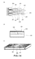
- FIG. 11 is a perspective view showing a recording apparatus to which the above described liquid ejection heads are applicable.
- FIGS. 12( a ) to 12 ( c ), FIGS. 13( a ) and 13 ( b ), and FIGS. 14( a ) to 14 ( c ) are schematic views for illustrating conventional liquid ejection heads.
- FIG. 1 is a plan view showing a principal portion of a liquid ejection head of this embodiment.
- the liquid ejection head of this embodiment includes ejection outlets 21 for ejecting ink as liquid, individual liquid chambers 16 communicating with the ejection outlets 21 , and a vibrational plate as an ejection energy generating means for generating energy for ejecting the liquid by expansion and contraction of the liquid in each individual liquid chamber 16 .
- the liquid ejection head is provided with a plurality of arranged individual liquid chambers 16 .
- the liquid ejection head further includes a common liquid chamber 19 for supplying the liquid to the plurality of individual liquid chambers 16 , an orifice communicating path 17 constituting a flow path for communicating an associated ejection outlet 21 and an associated individual liquid chamber 16 with each other, and a common liquid chamber communicating path 18 constituting a flow path for communicating the associated individual liquid chamber 16 and the common liquid chamber 19 with each other.
- Each of the individual liquid chambers 16 is formed in a substantially rectangular (rhombus) cross sectional shape with four corners where an ejection outlet 21 and three supply ports 20 for supplying the liquid from the common liquid chamber 19 are disposed.
- Each of the individual liquid chambers 16 is provided with an orifice communicating path 17 connected to an ejection outlet 21 and three common liquid chamber communicating paths 18 connected to the three supply ports 20 , respectively.
- flow paths are constituted by an orifice communicating path column-like portion and a common liquid chamber projected portion 10 , respectively, and are formed in a substantially V character-like, i.e., a so-called wedge-like, cross-sectional shape with respect to a direction perpendicular to an ejecting direction of the liquid.
- the V cross-sectional common liquid chamber projected portion 10 and the V cross-sectional orifice communicating path column-like portion 11 are opened toward a front end portion of the liquid ejection head with respect to a main scan direction (a travelling direction of the liquid ejection head during ejection of the ink from each ejection outlet).
- each individual liquid chamber 4 has a dimension, e.g., such that a length of a diagonal line connecting an ejection outlet 21 with a supply port 20 located diagonally with respect to the ejection outlet 21 is 500 ⁇ m and a length of a diagonal line connecting other (two) supply ports 20 is 300 ⁇ m.
- An angle formed between the diagonal line connecting the ejection outlet 21 of the orifice communicating path 17 for the individual liquid chamber 16 with the supply port 20 located diagonally with respect to the ejection outlet 21 and a row (X-axis in FIG. 1 ) direction perpendicular to the main scan direction is taken as an individual liquid chamber angle ⁇ 1 .
- This individual liquid chamber angle ⁇ 1 is determined by directions of the above-described V cross-sectional common liquid chamber projected portion 10 and orifice communicating path column-like portion 11 , an in-plane arrangement direction of each individual liquid chamber 16 , and an arrangement angle ⁇ 2 described below.
- FIG. 2 is a plan view showing the liquid ejection head of this embodiment, wherein 100 (10 ⁇ 10) individual liquid chambers 16 each having the shape shown in FIG. 1 are arranged in a plane. As shown in FIG. 2 , the plurality of individual liquid chambers 16 is arranged in an area surrounded by a common liquid chamber partition wall 12 .
- the liquid ejection head is provided with, as shown in FIG. 3 , the common liquid chamber 19 on a layer on which the individual liquid chambers 16 are arranged.
- an angle formed by an arrangement direction of the ejection outlets 21 of the individual liquid chambers 16 arranged roughly along a row (X-axis in FIG. 2 ) direction perpendicular to the main scan direction and the X-axis is taken as the arrangement axis ⁇ 2 .
- the arrangement angle ⁇ 2 may desirably be a non-zero finite value.
- the ejection outlets 21 are arranged so that those arranged in a column (Y-axis) direction ( FIG. 2 ) are shifted every column with respect to the row (X-axis) direction.
- the liquid ejection head of this embodiment is prepared by applying four substrates (first to fourth substrates) to each other.
- FIG. 3 is a perspective view showing the liquid ejection head exploded into patterned four substrates.
- a substrate 3 may desirably be subjected to patterning after a substrate 2 and the substrate 3 are bonded to each other. This is because a sufficient mechanical strength can be obtained by the bonding between the substrates 2 and 3 .
- FIG. 4 is a sectional view showing a constitution in which flow path lengths of the common liquid chamber communicating paths 18 with respect to adjacent three individual liquid chambers 16 are different from each other.
- three flow paths constituted by three common liquid chamber communicating paths 18 a , 18 b and 18 c have communicating positions, at different portions as seen in a direction perpendicular to a direction of ejection of the liquid through the ejection outlets 21 , with the common liquid chamber 19 . That is, as shown in FIG. 4 , the adjacent three individual liquid chambers 16 are provided with three common liquid chamber communicating paths 18 a , 18 b and 18 c , respectively, different in flow path length for connecting the common liquid chamber 19 to an associated supply port 20 .
- each of the common liquid chamber communicating paths 18 a , 18 b and 18 c different in flow path length is connected to the same common liquid chamber 19 .
- the individual liquid chambers 16 are classified into a plurality of groups associated with the common liquid chamber communicating paths different in flow path length.
- substrates 1 , 2 and 3 of three types for patterning are prepared.
- the substrates 1 , 2 and 3 e.g., an Si substrate or an SOI substrate or the like is used but the SOI substrate may desirably be used in view of a patterning step described below.
- each of the substrates 1 and 2 comprises a 200 ⁇ m-thick SOI substrate consisting of a 199.5 ⁇ m-thick silicon (Si) layer and a 0.5 ⁇ m-thick silicon oxide (SiO 2 ) layer.
- the substrate 3 comprises a 400 ⁇ m-thick SOI substrate consisting of a 399.5 ⁇ m-thick silicon (Si) layer and a 0.5 ⁇ m-thick silicon oxide (SiO 2 ) layer.
- a vibrational plate 22 of silicon (Si) is formed in a thickness of, e.g., 6 ⁇ m.
- a 0.3 ⁇ m-thick platinum (Pt) lower electrode 13 is formed at a bottom surface of the individual liquid chamber 16 .
- PZT lead zirconate titanate
- a 0.3 ⁇ m-thick platinum (Pt) upper electrode 15 are formed and used in combination with the vibrational plate 22 as an expansion and contraction means for the individual liquid chamber 16 .
- the substrate 2 is subjected to patterning of an orifice communicating path 17 with a diameter of 60 ⁇ m and three common liquid chamber communicating paths 18 a , 18 b and 18 c each with a diameter of 10 ⁇ m.
- the substrate 3 is subjected to patterning of the orifice communicating path 17 and the common liquid chambers 18 a , 18 b and 18 c different in length from each other. These patterning operations are performed by, e.g., chemical etching or ion milling. After the patterning operations of the substrates 1 , 2 and 3 , each of the substrates 1 , 2 and 3 is subjected to a flattening process.
- bonding of the substrate 1 , 2 and 3 is carried out.
- bonding between the substrates 2 and 3 which are the SOI substrates is performed so that the silicon oxide (SiO 2 ) layers are located as the upper layer of the substrate 2 and the lower layer of the substrate 3 .
- the silicon oxide (SiO 2 ) film has a function of arresting the progression of the patterning when the common liquid chamber projected portion 10 associated with the common liquid chamber communicating path 18 b is processed.
- the bonding of the substrates 1 , 2 and 3 is carried out with gold (Au)-gold (Au) bonding.
- the patterning of the common liquid chamber 19 is performed in an area other than those for the orifice communicating path 17 and the common liquid chamber communicating paths 18 b and 18 c .
- This patterning is effected by chemical etching or ion milling.
- FIG. 5( c ) shows a process for performing the patterning through the chemical etching and shows a state immediately after the chemical etching is effected. Thereafter, a resist 51 is removed.
- FIG. 5( d ) a second step of the patterning of the common liquid chamber 19 is performed.
- patterning is performed in an area of an upper portion of the common liquid chamber communicating path 18 .
- This patterning is carried out by the chemical etching or the ion milling.
- FIG. 5( d ) shows a process for performing the patterning through the chemical etching and shows a state immediately after the resist 51 is applied and the chemical etching is performed. By this chemical etching, the upper portion of the common liquid chamber communicating path 18 b is patterned.
- further progression of the etching is arrested. After the patterning, the resist 51 is removed and then flattening process of the substrate 3 is performed.
- the substrate 4 for patterning is prepared.
- the substrate 4 e.g., an Si substrate or an SOI substrate or the like is used, but the SOI substrate may desirably be used from the viewpoint of the patterning.
- the substrate 4 may, e.g., comprise a 200 ⁇ m-thick SOI substrate consisting of a 199.5 ⁇ m-thick Si layer and a 0.5 ⁇ m-thick SiO2 layer.
- the substrate 4 is subjected to patterning of the orifice communicating path 17 , the common liquid chamber 19 , and ejection outlets 21 with, e.g., a diameter of 30 ⁇ m and a height of 50 ⁇ m. This patterning is performed through, e.g., the chemical etching or ion milling. After the patterning, a flattening process of the substrate 4 is performed.
- bonding between the substrate 3 and the substrate 4 is effected.
- the bonding is effected through, e.g., gold (Au)-gold (Au) bonding.
- the substrates 1 , 2 , 3 and 4 are integrated.
- the individual liquid chambers 16 in the liquid ejection head of this embodiment are classified into the plurality of groups in which the flow path lengths of the common liquid chamber communicating paths 18 are different from each other and the same common liquid chamber 19 is connected to the respective common liquid chamber communicating paths 18 a , 18 b and 18 c . That is, the flow path lengths of the common liquid chamber communicating paths 18 a , 18 b and 18 c each connected to the same common liquid chamber 19 are provided in a plurality of different lengths. In other words, communicating positions (openings) of the common liquid chamber communicating paths 18 in the common liquid chamber 19 are different with respect to a vertical direction. Particularly, it is preferable that adjacent common liquid chamber communicating paths 18 are different in height of the opening.
- the liquid ejection head of this embodiment has the common liquid chamber communicating path projected portions 10 and the orifice communicating path column-like portions 11 which are formed in the substantially V character-like cross section opening toward the front end of the liquid ejection head with respect to the main scan direction.
- the order of the ejecting operation of the respective individual liquid chambers 16 substantially coincides with the position of the liquid ejection head in the main scan direction.
- the liquid ejection head is provided with the plurality of common liquid chamber communicating paths 18 each connected to an associated individual liquid chamber 16 .
- the liquid is forcedly ejected during a refreshing operation of an ejection characteristic.
- it is possible to easily discharge a bubble entering or generated in the inside of the individual liquid chamber 16 to the outside of the liquid ejection head through the ejection outlet 21 .
- it is possible to sufficiently ensure supply of the liquid from the common liquid chamber 19 to the individual liquid chambers 16 .
- the flow path lengths of the plurality of common liquid chamber communicating paths 18 connected to the same common liquid chamber 19 may be the same or different from each other.
- Second Embodiment will be described with reference to FIG. 6 and FIGS. 7( a ) to 7 ( e ).
- First Embodiment three types of the different flow path lengths are set with respect to the common liquid chamber communicating paths 18 connected to the same common liquid chamber 19 .
- two types of different flow path lengths with respect to common liquid chamber communicating paths 18 connected to the same common liquid chamber 19 are employed. It is preferable that at least heights of adjacent openings of the common liquid chamber communicating paths 18 communicating with the common liquid chamber 19 are different from each other. As described with reference to FIGS.
- the number of types of the different flow path lengths of the common liquid chamber communicating paths 18 connected to the same common liquid chamber 19 is reduced to two, so that patterning of the common liquid chamber 19 can be carried out in one step to further facilitate a production step of the common liquid chamber 19 .
- FIGS. 7( a ) to 7 ( e ) are sectional views for illustrating a production process of the entire liquid ejection head of this embodiment.
- a wafer and a processing method necessary to produce the liquid ejection head in this embodiment and those in First Embodiment are in common with each other in some steps.
- the steps shown in FIGS. 7( a ) and 7 ( b ) are identical to those shown in FIGS. 5( a ) and 5 ( b ), respectively.
- Patterned substrates 1 , 2 and 3 are prepared and bonded to each other.
- patterning of the common liquid chamber 19 is performed in an area other than those for the orifice communicating paths 17 and the common liquid chamber communicating path 18 c .
- This patterning is effected through, e.g., the chemical etching or the ion milling.
- FIG. 7( c ) shows a process for effecting through the chemical etching and shows a state immediately after the chemical etching. After the patterning, the resist 51 is removed and the substrate 3 is subjected to a flattening processing. Finally, as shown in FIG.
- patterned substrate 4 is prepared and bonded to the substrate 3 through, e.g., gold (Au)-gold (Au) bonding to complete a structure as shown in FIG. 7( e ).
- Au gold
- Au gold
- FIGS. 7( d ) and 7 ( e ) are identical to those shown in FIGS. 5( e ) and 5 ( f ) described above, respectively.
- the number of the substrates constituting the liquid ejection head is smaller than those in First and Second Embodiments by one. That is, the liquid ejection head is constituted by bonding three substrates to each other. Therefore, a production process is further easily performed compared with those in First and Second Embodiments.
- FIG. 8 is a perspective view showing exploded and patterned through substrates for constituting the liquid ejection head of this embodiment, wherein the three substrates consisting of a substrate 1 , a substrate 5 and a substrate 4 are bonded to each other to constitute the liquid ejection head.
- the liquid ejection head is produced by bonding the substrate 1 and the substrate 4 to each other after the substrate 5 is subjected to patterning.
- FIGS. 9( a ) to 9 ( j ) are sectional views for illustrating a production process of the entire liquid ejection head of this embodiment.
- FIGS. 9( a ) to 9 ( h ) illustrate a method of patterning the substrate 5 .
- the patterning of the substrate 5 is effected through anodization.
- the anodization is a method in which electrolysis is performed in a hydrogen fluoride solution by using a substrate to be subjected to patterning (e.g., a silicon (Si) substrate) as an anode electrode and the other metal plate (e.g., a platinum (Pt) substrate) as a cathode electrode.
- a substrate to be subjected to patterning e.g., a silicon (Si) substrate
- the other metal plate e.g., a platinum (Pt) substrate
- Si is finally changed to H 2 SiF 6 through the following four reactions (2) to to be dissolved in the hydrogen fluoride solution.
- SiF 2 ⁇ Si*+SiF 4 (2) SiF 4 +2HF ⁇ H 2 SiF 6 (3) Si*+2H 2 O ⁇ SiO 2 +2H 2 (4) SiO 2 +6HF ⁇ H 2 SiF 6 +2H 2 O (5)
- h + represents a hole and in the reactions (2) and (4), Si* represents amorphous silicon.
- the reaction (4) is particularly slow. Accordingly, a method in which an St substrate with a portion intended to be subjected to the patterning is changed into silicon oxide (SiO 2 ) in advance is immersed in the hydrogen fluoride solution to form H 2 SiF 6 only by the reaction (5) is effective. According to this method, the chemical reactions (1) to (4) are not required, so that the electrolysis as described above is also not required to be carried out. As a result, the patterning can be effected by only immersing the Si substrate in the hydrogen fluoride solution.
- FIG. 9( g ) a method in which an Si substrate 5 with a portion, intended to be subjected to the patterning, which has been changed into the silicon oxide (SiO 2 ) in advance is prepared and immersed in the hydrogen fluoride solution to a structure as shown in FIG. 9( h ) is considered.
- the substrate 5 for patterning is prepared.
- the substrate 5 e.g., an Si substrate or an SOI substrate or the like is used. However, in either case, a p-type Si substrate or a p-type SOI substrate is required to be used.
- the substrate 5 is formed in a thickness of, e.g., about 200 ⁇ m.
- a silicon nitride film 52 is formed and used as a mask for the patterning. In this state, the substrate 5 is heat-oxidized to form a silicon oxide layer 53 but the silicon nitride film 52 functions as the mask during the patterning. For this reason, the silicon portion covered with the silicon nitride film 52 is not oxidized. Thereafter, the silicon nitride film 52 is removed from the substrate 5 to form a structure shown in FIG. 9( b ).
- a silicon oxide film 53 is formed by, e.g., an epitaxial growth method or the like.
- a polysilicon film 54 is laminated on the substrate 5 by, e.g., the epitaxial growth method or the like to create a state shown in FIG. 9( d ).
- the silicon nitride film 52 is laminated on the substrate 5 and subjected to the oxidization processing again.
- the substrate 5 from which the silicon nitride film 52 is removed is shown in FIG. 9( e ).
- the polysilicon film 54 is laminated in a thickness of, e.g., 200 ⁇ m on the substrate 5 again by the epitaxial growth method or the like to create a state shown in FIG. 9( f ).
- the substrate 5 is subjected to patterning of the orifice communicating paths 17 and the common liquid chamber communicating paths 18 a , 18 b and 18 c .
- This patterning is performed through, e.g., the chemical etching or the ion milling.
- the silicon oxide film 53 functions as a stopper (etching stopper film) for the patterning, so that the patterning does not progress toward a lower portion than the silicon oxide film 53 .
- the substrate 5 is subjected to the flattening processing. The substrate 5 at this time is shown in FIG. 9( g ).
- the substrate 5 is patterned.
- the patterning is performed in the hydrogen fluoride solution by immersing the substrate 5 in the solution.
- FIG. 9( h ) a shape of the substrate 5 after the patterning is shown.
- FIGS. 9( i ) and 9 ( j ) show steps for completing the liquid ejection head by turning the substrate 5 subjected to the patterning in the steps shown in FIGS. 5( a ) to 6 ( h ) upside down and placing the substrate 5 between the substrates 1 and 4 , followed by bonding of these substrates.
- patterned substrates 1 and 4 are prepared. These substrates 1 and 4 are, e.g., the same as the patterned substrates used in First and Second Embodiments.
- the bonding of the substrates 1 , 5 and 4 is performed so that these substrates are laminated in this order. This bonding is effected through, e.g., gold (Au)-gold (Au) bonding.
- FIG. 10 is an exploded perspective view of a liquid ejection head of this embodiment.
- an orifice communicating path 17 in this embodiment is constituted by an orifice communicating path column-like portion 11 formed in a substantially triangular cross section.
- On side of the triangular cross-sectional orifice communicating path column-like portion 11 is disposed to face the space defined by the V cross-sectional common liquid chamber communicating path projected portion.
- the orifice communicating path column-like portion 11 is formed in the substantially triangular cross section, so that compared with First Embodiment employing the V cross-sectional orifice communicating path column-like portion, processing of the orifice communicating path column-like portion is easily performed.
- this embodiment has the advantage that positional deviation between a substrate 6 and a substrate 4 can be reduced when these substrates are bonded to each other.
- the liquid ejection head of this embodiment is constituted by bonding four substrates consisting of the substrates 1 , 2 , 6 and 4 similarly as in First Embodiment.
- the substrate 6 is provided with the triangular cross-sectional orifice communicating path column-like portions 11 .
- the patterning of the substrate 6 may desirably be performed after the bonding between the substrates 2 and 6 .
- the liquid ejection head of this embodiment can be produced in the same manner as in First Embodiment described with reference to FIGS. 5( a ) to 5 ( f ). The description of the production process will be omitted.
- FIG. 11 is a perspective view showing a recording apparatus to which the present invention is applicable.
- a recording material P supplied to the recording apparatus is conveyed by a pair of conveying rollers 109 and 110 to an area in which recording can be made by a liquid ejection head unit 100 .
- the liquid ejection head unit 100 is guided by a pair of guiding shafts 107 and 102 , being enabled to be reciprocally moved along the guiding shafts 107 and 102 in the direction (main scan direction) parallel to the direction in which the guiding shafts 107 and 102 extend.
- the scan direction of the liquid ejection head unit 100 is the main scan direction, and the direction in which the recording material P is conveyed is a sub-scan direction.
- liquid ejection heads 113 shown in FIG. 2 (plan view) and a plurality of ink containers 101 for supplying inks to a common liquid chamber 19 are mounted.
- the ink containers 101 include ink containers 101 B, 101 C, 101 M and 101 Y of four colors of black (Bk), cyan (C), magenta (M), and yellow (Y) inks.
- a refreshing unit 112 for refreshing an ejection characteristic of the liquid ejection head 113 is disposed below a right end portion in a movable range of the liquid ejection head unit 100 .
- the refreshing unit 112 refreshes the ejection characteristic, e.g., by forcely ejecting the ink(s) from the ejection outlets 21 of the liquid ejection head 113 during a non-recording operation.
- the ink containers 101 B, 101 C, 101 M and 101 Y of Bk, C, M and Y are structured so that the ink containers can be replaced independently from each other.
- the ink container 101 B for Bk ink, the ink container 101 C for C ink, the ink container 101 M for M ink, and the ink container 101 Y for Y ink are mounted.
- the liquid ejection heads are mounted, respectively, so that each of the inks is supplied to an associated common liquid chamber 19 of each of the liquid ejection heads.
Landscapes
- Engineering & Computer Science (AREA)
- Manufacturing & Machinery (AREA)
- Particle Formation And Scattering Control In Inkjet Printers (AREA)
Abstract
Description
Si+2HF+2h +→SiF2+2H+ (1)
2SiF2→Si*+SiF4 (2)
SiF4+2HF→H2SiF6 (3)
Si*+2H2O→SiO2+2H2 (4)
SiO2+6HF→H2SiF6+2H2O (5)
Claims (9)
Applications Claiming Priority (2)
| Application Number | Priority Date | Filing Date | Title |
|---|---|---|---|
| JP2007178286A JP4979488B2 (en) | 2007-07-06 | 2007-07-06 | Liquid ejection head and recording apparatus |
| JP2007-178286 | 2007-07-06 |
Publications (2)
| Publication Number | Publication Date |
|---|---|
| US20090021562A1 US20090021562A1 (en) | 2009-01-22 |
| US7802875B2 true US7802875B2 (en) | 2010-09-28 |
Family
ID=40264494
Family Applications (1)
| Application Number | Title | Priority Date | Filing Date |
|---|---|---|---|
| US12/167,652 Active 2029-02-10 US7802875B2 (en) | 2007-07-06 | 2008-07-03 | Liquid ejection head and recording apparatus |
Country Status (2)
| Country | Link |
|---|---|
| US (1) | US7802875B2 (en) |
| JP (1) | JP4979488B2 (en) |
Families Citing this family (1)
| Publication number | Priority date | Publication date | Assignee | Title |
|---|---|---|---|---|
| JP7318398B2 (en) * | 2019-07-31 | 2023-08-01 | セイコーエプソン株式会社 | Liquid ejection head and liquid ejection device |
Citations (8)
| Publication number | Priority date | Publication date | Assignee | Title |
|---|---|---|---|---|
| JP2000158645A (en) | 1998-11-25 | 2000-06-13 | Matsushita Electric Ind Co Ltd | Ink jet head |
| JP2001334661A (en) | 2000-03-21 | 2001-12-04 | Nec Corp | Ink jet head |
| US6488355B2 (en) | 2000-03-21 | 2002-12-03 | Fuji Xerox Co., Ltd. | Ink jet head |
| JP3666386B2 (en) | 2000-11-30 | 2005-06-29 | ブラザー工業株式会社 | Inkjet printer head |
| US7121650B2 (en) * | 2001-12-18 | 2006-10-17 | Samsung Electronics Co., Ltd. | Piezoelectric ink-jet printhead |
| US7338151B1 (en) * | 1998-06-30 | 2008-03-04 | Canon Kabushiki Kaisha | Head for ink-jet printer having piezoelectric elements provided for each ink nozzle |
| US20080239016A1 (en) | 2007-03-26 | 2008-10-02 | Canon Kabushiki Kaisha | Liquid discharge head and liquid discharge apparatus |
| US7585061B2 (en) * | 2004-08-27 | 2009-09-08 | Fujifilm Corporation | Ejection head and image forming apparatus |
Family Cites Families (1)
| Publication number | Priority date | Publication date | Assignee | Title |
|---|---|---|---|---|
| JP2005125696A (en) * | 2003-10-27 | 2005-05-19 | Canon Inc | Inkjet recording head |
-
2007
- 2007-07-06 JP JP2007178286A patent/JP4979488B2/en active Active
-
2008
- 2008-07-03 US US12/167,652 patent/US7802875B2/en active Active
Patent Citations (8)
| Publication number | Priority date | Publication date | Assignee | Title |
|---|---|---|---|---|
| US7338151B1 (en) * | 1998-06-30 | 2008-03-04 | Canon Kabushiki Kaisha | Head for ink-jet printer having piezoelectric elements provided for each ink nozzle |
| JP2000158645A (en) | 1998-11-25 | 2000-06-13 | Matsushita Electric Ind Co Ltd | Ink jet head |
| JP2001334661A (en) | 2000-03-21 | 2001-12-04 | Nec Corp | Ink jet head |
| US6488355B2 (en) | 2000-03-21 | 2002-12-03 | Fuji Xerox Co., Ltd. | Ink jet head |
| JP3666386B2 (en) | 2000-11-30 | 2005-06-29 | ブラザー工業株式会社 | Inkjet printer head |
| US7121650B2 (en) * | 2001-12-18 | 2006-10-17 | Samsung Electronics Co., Ltd. | Piezoelectric ink-jet printhead |
| US7585061B2 (en) * | 2004-08-27 | 2009-09-08 | Fujifilm Corporation | Ejection head and image forming apparatus |
| US20080239016A1 (en) | 2007-03-26 | 2008-10-02 | Canon Kabushiki Kaisha | Liquid discharge head and liquid discharge apparatus |
Also Published As
| Publication number | Publication date |
|---|---|
| JP4979488B2 (en) | 2012-07-18 |
| US20090021562A1 (en) | 2009-01-22 |
| JP2009012367A (en) | 2009-01-22 |
Similar Documents
| Publication | Publication Date | Title |
|---|---|---|
| US9415597B2 (en) | Ink jet head having nozzle plate equipped with piezoelectric elements | |
| US8047632B2 (en) | Ink jet recording head | |
| EP1815991B1 (en) | Piezoelectric inkjet printhead | |
| JP5454016B2 (en) | Inkjet head | |
| US6676844B2 (en) | Method for manufacturing ink-jet printhead having hemispherical ink chamber | |
| JP5573052B2 (en) | Inkjet head | |
| US20020089570A1 (en) | Ink-jet printhead having hemispherical ink chamber and method for manufacturing the same | |
| US7980675B2 (en) | Ink jet head | |
| US20070052759A1 (en) | Inkjet printhead and method of manufacturing the same | |
| JP5849131B1 (en) | Ink jet head and manufacturing method thereof | |
| US6652077B2 (en) | High-density ink-jet printhead having a multi-arrayed structure | |
| US7802875B2 (en) | Liquid ejection head and recording apparatus | |
| JP6047548B2 (en) | Inkjet recording head | |
| JP4665455B2 (en) | Silicon structure manufacturing method, mold manufacturing method, molded member manufacturing method, silicon structure, ink jet recording head, and image forming apparatus | |
| JP6360949B2 (en) | Inkjet printer | |
| US8356887B2 (en) | Piezoelectric element, and liquid ejection head and recording apparatus using the piezoelectric element | |
| JP6181830B2 (en) | Method for manufacturing ink jet recording head | |
| US7568784B2 (en) | Inkjet printhead and method of manufacturing the same | |
| JP7220328B1 (en) | HEAD CHIP, LIQUID JET HEAD AND LIQUID JET RECORDING APPARATUS | |
| US20240051298A1 (en) | Method for manufacturing substrate bonded body and method for manufacturing liquid ejection substrate | |
| JP2002240293A (en) | Liquid drop jet recorder and method for manufacturing silicon structure | |
| JPH11157060A (en) | Ink jet head | |
| JP3419376B2 (en) | Ink jet recording head | |
| JP3564853B2 (en) | Method of manufacturing ink jet head and printer using the head | |
| JP2001162791A (en) | Ink jet recording head |
Legal Events
| Date | Code | Title | Description |
|---|---|---|---|
| AS | Assignment |
Owner name: CANON KABUSHIKI KAISHA, JAPAN Free format text: ASSIGNMENT OF ASSIGNORS INTEREST;ASSIGNORS:MIURA, KAORU;KITAKAMI, KOICHI;REEL/FRAME:022706/0819;SIGNING DATES FROM 20080628 TO 20080629 Owner name: CANON KABUSHIKI KAISHA, JAPAN Free format text: ASSIGNMENT OF ASSIGNORS INTEREST;ASSIGNORS:MIURA, KAORU;KITAKAMI, KOICHI;SIGNING DATES FROM 20080628 TO 20080629;REEL/FRAME:022706/0819 |
|
| STCF | Information on status: patent grant |
Free format text: PATENTED CASE |
|
| FEPP | Fee payment procedure |
Free format text: PAYOR NUMBER ASSIGNED (ORIGINAL EVENT CODE: ASPN); ENTITY STATUS OF PATENT OWNER: LARGE ENTITY |
|
| FPAY | Fee payment |
Year of fee payment: 4 |
|
| MAFP | Maintenance fee payment |
Free format text: PAYMENT OF MAINTENANCE FEE, 8TH YEAR, LARGE ENTITY (ORIGINAL EVENT CODE: M1552) Year of fee payment: 8 |
|
| MAFP | Maintenance fee payment |
Free format text: PAYMENT OF MAINTENANCE FEE, 12TH YEAR, LARGE ENTITY (ORIGINAL EVENT CODE: M1553); ENTITY STATUS OF PATENT OWNER: LARGE ENTITY Year of fee payment: 12 |