US7799062B2 - Self-guiding threaded fastener - Google Patents
Self-guiding threaded fastener Download PDFInfo
- Publication number
- US7799062B2 US7799062B2 US11/000,098 US9804A US7799062B2 US 7799062 B2 US7799062 B2 US 7799062B2 US 9804 A US9804 A US 9804A US 7799062 B2 US7799062 B2 US 7799062B2
- Authority
- US
- United States
- Prior art keywords
- thread
- orthopedic
- shank
- diameter
- screw
- Prior art date
- Legal status (The legal status is an assumption and is not a legal conclusion. Google has not performed a legal analysis and makes no representation as to the accuracy of the status listed.)
- Active, expires
Links
- 230000000399 orthopedic effect Effects 0.000 claims abstract description 129
- 210000000988 bone and bone Anatomy 0.000 claims abstract description 83
- 239000007943 implant Substances 0.000 claims abstract description 62
- 238000000034 method Methods 0.000 claims description 16
- 238000004891 communication Methods 0.000 claims description 5
- 230000007704 transition Effects 0.000 claims description 4
- 238000005553 drilling Methods 0.000 claims description 3
- 239000011295 pitch Substances 0.000 claims 16
- 230000004927 fusion Effects 0.000 abstract description 5
- 230000006641 stabilisation Effects 0.000 abstract description 4
- 238000011105 stabilization Methods 0.000 abstract description 4
- 239000000463 material Substances 0.000 description 6
- 238000013461 design Methods 0.000 description 4
- 238000001356 surgical procedure Methods 0.000 description 3
- 230000006870 function Effects 0.000 description 2
- 238000003780 insertion Methods 0.000 description 2
- 230000037431 insertion Effects 0.000 description 2
- 238000012986 modification Methods 0.000 description 2
- 230000004048 modification Effects 0.000 description 2
- 238000007747 plating Methods 0.000 description 2
- 229920000049 Carbon (fiber) Polymers 0.000 description 1
- 229910001200 Ferrotitanium Inorganic materials 0.000 description 1
- RTAQQCXQSZGOHL-UHFFFAOYSA-N Titanium Chemical compound [Ti] RTAQQCXQSZGOHL-UHFFFAOYSA-N 0.000 description 1
- 229910045601 alloy Inorganic materials 0.000 description 1
- 239000000956 alloy Substances 0.000 description 1
- 238000004873 anchoring Methods 0.000 description 1
- 239000004917 carbon fiber Substances 0.000 description 1
- 239000000919 ceramic Substances 0.000 description 1
- 239000002131 composite material Substances 0.000 description 1
- 230000008602 contraction Effects 0.000 description 1
- 230000008878 coupling Effects 0.000 description 1
- 238000010168 coupling process Methods 0.000 description 1
- 238000005859 coupling reaction Methods 0.000 description 1
- 229910003460 diamond Inorganic materials 0.000 description 1
- 239000010432 diamond Substances 0.000 description 1
- 238000000605 extraction Methods 0.000 description 1
- 210000002758 humerus Anatomy 0.000 description 1
- 238000002513 implantation Methods 0.000 description 1
- 208000014674 injury Diseases 0.000 description 1
- 238000004519 manufacturing process Methods 0.000 description 1
- 230000013011 mating Effects 0.000 description 1
- 229910052751 metal Inorganic materials 0.000 description 1
- 239000002184 metal Substances 0.000 description 1
- VNWKTOKETHGBQD-UHFFFAOYSA-N methane Chemical compound C VNWKTOKETHGBQD-UHFFFAOYSA-N 0.000 description 1
- 230000002980 postoperative effect Effects 0.000 description 1
- 230000008569 process Effects 0.000 description 1
- 230000001737 promoting effect Effects 0.000 description 1
- 238000004513 sizing Methods 0.000 description 1
- 239000010935 stainless steel Substances 0.000 description 1
- 229910001220 stainless steel Inorganic materials 0.000 description 1
- 239000010936 titanium Substances 0.000 description 1
- 230000008733 trauma Effects 0.000 description 1
- 210000000689 upper leg Anatomy 0.000 description 1
Images


Classifications
-
- A—HUMAN NECESSITIES
- A61—MEDICAL OR VETERINARY SCIENCE; HYGIENE
- A61B—DIAGNOSIS; SURGERY; IDENTIFICATION
- A61B17/00—Surgical instruments, devices or methods, e.g. tourniquets
- A61B17/56—Surgical instruments or methods for treatment of bones or joints; Devices specially adapted therefor
- A61B17/58—Surgical instruments or methods for treatment of bones or joints; Devices specially adapted therefor for osteosynthesis, e.g. bone plates, screws, setting implements or the like
- A61B17/68—Internal fixation devices, including fasteners and spinal fixators, even if a part thereof projects from the skin
- A61B17/80—Cortical plates, i.e. bone plates; Instruments for holding or positioning cortical plates, or for compressing bones attached to cortical plates
- A61B17/8052—Cortical plates, i.e. bone plates; Instruments for holding or positioning cortical plates, or for compressing bones attached to cortical plates immobilised relative to screws by interlocking form of the heads and plate holes, e.g. conical or threaded
- A61B17/8057—Cortical plates, i.e. bone plates; Instruments for holding or positioning cortical plates, or for compressing bones attached to cortical plates immobilised relative to screws by interlocking form of the heads and plate holes, e.g. conical or threaded the interlocking form comprising a thread
-
- A—HUMAN NECESSITIES
- A61—MEDICAL OR VETERINARY SCIENCE; HYGIENE
- A61B—DIAGNOSIS; SURGERY; IDENTIFICATION
- A61B17/00—Surgical instruments, devices or methods, e.g. tourniquets
- A61B17/56—Surgical instruments or methods for treatment of bones or joints; Devices specially adapted therefor
- A61B17/58—Surgical instruments or methods for treatment of bones or joints; Devices specially adapted therefor for osteosynthesis, e.g. bone plates, screws, setting implements or the like
- A61B17/68—Internal fixation devices, including fasteners and spinal fixators, even if a part thereof projects from the skin
- A61B17/84—Fasteners therefor or fasteners being internal fixation devices
- A61B17/86—Pins or screws or threaded wires; nuts therefor
- A61B17/8625—Shanks, i.e. parts contacting bone tissue
- A61B17/863—Shanks, i.e. parts contacting bone tissue with thread interrupted or changing its form along shank, other than constant taper
-
- A—HUMAN NECESSITIES
- A61—MEDICAL OR VETERINARY SCIENCE; HYGIENE
- A61B—DIAGNOSIS; SURGERY; IDENTIFICATION
- A61B17/00—Surgical instruments, devices or methods, e.g. tourniquets
- A61B17/56—Surgical instruments or methods for treatment of bones or joints; Devices specially adapted therefor
- A61B17/58—Surgical instruments or methods for treatment of bones or joints; Devices specially adapted therefor for osteosynthesis, e.g. bone plates, screws, setting implements or the like
- A61B17/68—Internal fixation devices, including fasteners and spinal fixators, even if a part thereof projects from the skin
- A61B17/84—Fasteners therefor or fasteners being internal fixation devices
- A61B17/86—Pins or screws or threaded wires; nuts therefor
- A61B17/8685—Pins or screws or threaded wires; nuts therefor comprising multiple separate parts
Definitions
- the present invention relates to the fixation of orthopedic implants, including fasteners to bones and other orthopedic devices and fasteners for effecting such fixation, as well as associated methods.
- Orthopedic surgery whether it be for fracture fixation, joint reconstruction, spine stabilization or fusion, often comprises the fastening of an implant, including an orthopedic plate, to a bone or to another implant or component of a trauma, reconstructive or fusion system.
- a screw fastener is used in conjunction with an aperture in an orthopedic implant, and the threads of the screw fastener engage bone or another component of the system as indicated above.
- the screw fastener would include not only threads to engage the bony material, but also threads to engage the female threads in a threaded aperture.
- orthopedic screws In order to accomplish the goal of fixing orthopedic plates to the bone, orthopedic screws have been constructed with threads designed for engaging bony structures. This enables the screw to be tightly positioned against the plate and bone.
- the aperture of the orthopedic plate in which the screw is received often includes internal threads for coupling the bone screw to the orthopedic implant. Since many screws are designed to specifically have threads which are best adapted for anchoring in bony material, often the engagement between the screw and the orthopedic plate is not optimized.
- the part of the shank which is designed to be disposed within the bone may include external threads specifically adapted to engage bony material.
- the second thread has a conical configuration.
- a bone screw may also be designed having a conical shank portion.
- the entire shank of the bone screw may be conical or the conical shank may be limited to only a portion of the shank.
- the shank portion that is disposed within an aperture of a bone plate may be conical while the bone engaging portion is not.
- a fastener in accordance with the present invention can be used as a monoaxial fastener in a plate or other device having an aperture with a female thread.
- the fastener includes a single thread, the profile which is the same throughout the length of the fastener from the trailing end or proximal end at the bottom of the head (if there is a head) to the leading end or distal end of the fastener.
- the pitch and depth of the thread is the same.
- that portion of the shank of the screw fastener i.e., the plate engaging portion of the shank—has a different thickness than the remaining shaft of the screw fastener.
- the root diameter of the fastener shank (the thickness of the shank without the threads) is larger in the plate engaging portion, and this plate engaging portion is sized to lock with the plate as the bone engaging portion threads into the bone.
- the bone engaging portion of the fastener shank is sized to permit the thread to fit loosely between the female threads of the plate throughout the bone engaging portion of the shaft. This facilitates the threading process and avoids cross-threading.
- the fastener in any one of the permeations discussed above, can be used in connection with a coupler having an internal thread, the coupler being positioned in a through-hole of a plate.
- the fastener may not have a head so that the coupler can facilitate polyaxial movement of the fastener.
- a coupler might be a ball-shaped coupler or a coupler having spherical surfaces to permit polyaxial movement of the fastener.
- the fastener would self-thread into the internal thread of the coupler in the same fashion as described above.
- the coupler-engaging portion of the fastener engages the internal thread of the coupler, the threading is tight between the coupler thread and the thread in the coupler engaging portion of the fastener shank.
- an orthopedic screw for attachment to an orthopedic component in an orthopedic surgical procedure includes a shank, which includes a first portion and a second portion.
- the first portion having a first shank diameter and a first thread extending radially outward from the shank, said first thread defining a first thread diameter.
- the second portion includes a second shank diameter and a second thread extending radially outward from the second portion.
- the second thread has a second thread diameter.
- the second shank diameter and the second thread diameter are preferably smaller than the respective first shank diameter and first thread diameter.
- the second thread has a thread height and a pitch and the first thread has a thread height and a pitch.
- the thread height and pitch of the first thread are substantially equal to the thread height and pitch of the second thread, respectively.
- the orthopedic screw may also include a distal tip.
- the distal tip having a third shank extending from the second portion remote from the first portion and including a third thread extending radially outward from the third shank.
- the third has a thread height and a pitch.
- the thread height and pitch of the third thread height substantially equal to the thread height and pitch of the first and second portions.
- the distal tip may further include a first end remote from the second portion and at least one groove extending from the first end toward the second portion.
- the orthopedic screw preferably includes a recess disposed in at least the head of the screw.
- the recess may be in the shape of a polygon.
- the pitch of the first and second portion is approximately 1 millimeter. Additionally in one preferred embodiment of the present invention the thread height of the first and second portion is approximately 0.6 millimeters. Further the orthopedic screw may have a length between approximately 10 and 120 millimeters and with the first portion having a length between approximately 1 and 2.2 millimeters.
- an orthopedic screw for use in a surgical procedure.
- the orthopedic screw preferably includes a shank having a first portion and a second portion.
- the first portion preferably includes an engagement means adapted for engaging the screw relative to a second element.
- the second portion preferably includes an aligning means adapted for contacting the second element while being received within the second element.
- the aligning means further adapted for maintaining a correct relationship between the screw relative to the second element while being received within the second element until the second portion has surpassed the second element.
- an orthopedic implant and an orthopedic screw are provided.
- the orthopedic implant preferably includes at least one aperture with internal threads.
- the orthopedic screw preferably includes a head, a first portion and a second portion.
- the first portion has a shank with a first shank diameter and a first thread. The first thread extending radially outward from the shank to define a thread diameter.
- the second portion of the orthopedic screw has a shank with a second shank diameter and a second thread extending radially outward from the shank.
- the second shank diameter and the second thread diameter are preferably smaller than the first shank diameter and the second thread diameter.
- the second thread has a thread height and a pitch.
- the first thread also has a thread height and a pitch.
- the thread height and pitch of the first thread are substantially equal to the thread height and pitch of the second thread, respectively
- the second thread is adapted to be received in the aperture of the orthopedic implant and communicate with the internal threads of the orthopedic implant to maintain correct alignment between the orthopedic screw and the orthopedic implant.
- the first thread and the first shank diameter of said first portion are adapted to fully engage the internal threads of the at least one aperture of the orthopedic implant.
- the orthopedic implant may be a bone plate or a coupler as well as additional implants.
- a method of attaching an orthopedic implant to a patient preferably includes providing an orthopedic screw having a head, a first portion and a second portion.
- the first portion being in communication with the head and including a shank having a first inner diameter and a first thread extending radially outward from the shank.
- the first thread includes a first outer diameter.
- the orthopedic screw further includes a second portion including a second shank having a second inner diameter and a second thread extending radially outward from the second portion.
- the second thread has a second outer diameter.
- the second inner diameter and the second outer diameter are smaller than the first inner diameter and the first outer diameter.
- the second thread has a thread height and a pitch and the first thread has a thread height and a pitch.
- the thread height and pitch of the first thread are substantially equal to the thread height and pitch of the second thread, respectively.
- the method further includes providing an orthopedic implant, the implant having at least one aperture with an internal thread. Additional the method includes pre-drilling a hole into a bone to which the orthopedic implant will be attached to.
- the orthopedic implant in placed in correct spatial relation relative to the pre-drilled hole.
- the orthopedic screw is than aligned with the aperture of the implant.
- the orthopedic screw through is than translated through the aperture and into the predrilled hole, wherein said second portion of the orthopedic screw contacts the internal thread of the aperture in order that the orthopedic screw maintains a predetermined spatial relationship with regard to the orthopedic implant.
- the screw is further translated through the aperture of the orthopedic implant, wherein the first portion contacts the internal thread of the orthopedic implant to lock the orthopedic screw relative to the orthopedic implant.
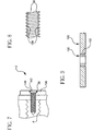
- FIG. 1 is a side view of one embodiment of the present invention
- FIG. 2 is a cut-out view of the embodiment of FIG. 1 illustrating one embodiment of a first portion
- FIG. 3 is a cut-out view of the embodiment of FIG. 1 illustrating one embodiment of a second portion
- FIG. 4 is a top view of one embodiment of an orthopedic implant used in combination with the embodiment of FIG. 1 ;
- FIG. 5 is a side view of the orthopedic implant of FIG. 4 in a method of use
- FIG. 6 is an enlarged cross-sectional view of the threads, screw and the female threads of an orthopedic implant of FIG. 4 ;
- FIG. 7 is a side view of an orthopedic implant of FIG. 4 , illustrating the fastener and further threaded into its fastened position;
- FIG. 8 is an enlarged cross-sectional view of the threads illustrating the cooperation between the plate engaging portion of a bone screw and the female threads of an orthopedic implant of FIG. 7 ;
- FIG. 9 illustrates an alternate embodiment of the orthopedic implant used in the present invention.
- bone screw 10 includes a head 12 and a shank 14 .
- Shank 14 extends downwardly from head 12 and preferably includes first portion 16 , second portion 18 and distal tip 20 .
- Shank 14 also preferably includes thread 22 extending radially outward from shank 14 .
- Thread 22 extends radially outward from shank 22 as well as substantially continuous from the proximal end of first portion 16 to distal tip 20 .
- first portion 16 resides in that portion of the shank 14 that engages the orthopedic implant, for instance a plate, when surgically implanted. There need not be exacting congruency in such engagement.
- the first portion 16 can partially engage the female threaded aperture of a plate, fully engage the female threaded aperture of a plate, or even extend beyond the bounds of the female threaded aperture of a plate.
- a substantial portion of a threaded aperture in a plate is engaged by the first portion 16 .
- the second portion 18 of the bone screw 10 engages bone, though it may engage another orthopedic component used in connection with fracture fixation, joint reconstruction, spinal stabilization or fusion, or any other component within an orthopedic system.
- the length of the second portion 18 need not be in proportion to the first portion 16 as shown in the drawings, but rather can be of any suitable length (and other parameters) as may be suitable for a particular application.
- Bone screw 10 as well as other elements which are described below, are preferably made from a biologically inert material, for example, any metal customarily used for surgical devices and particularly those used for bone screws and pins, such as titanium or stainless steel.
- suitable materials include, but are not limited to, alloys, composite materials, ceramics or carbon-fiber materials.
- first portion 16 of bone screw 10 includes first end 24 and second end 26 .
- First end 24 is preferably in communication with head 12 , though it need not be in every application.
- the first portion 16 is not tapered from its first end 24 to its second end 26 , but is instead of a constant diameter. Of course, a slight taper is still within the spirit of this preferred embodiment.
- Shank 14 has a first diameter D in first portion 16 .
- first diameter D representing the root diameter
- First portion 16 also includes first thread 30 which is preferably part of thread 22 .
- First thread 30 has a pitch P and a thread height T.
- thread height T is approximately in a range between 0.25 millimeters and 3 millimeters, as measured from the shank 14 .
- pitch P of first thread 30 is approximately between 0.8 millimeters and 1 millimeter.
- second portion 18 of shank 14 includes a first end 32 and second end 34 .
- First end 32 although not shown in FIG. 3 , is preferably attached to and extends from second end 26 of first portion 16 .
- Such a chamfer is a well-known engineering expedient to facilitate manufacture and to break sharp edges.
- Such chamfer is shown slightly in FIG. 1 .
- Second portion 18 has a second diameter D′, representing the root diameter.
- second diameter D′ is between approximately 2.5 millimeters and 4.5 millimeters.
- Second portion 18 of shank 14 also includes second thread 36 extending radially outward from shank 14 .
- Second thread 36 is preferably part of thread 22 and is continuous with first thread 30 .
- Second thread 36 has a pitch P′ and a thread height T′.
- pitch P′ is approximately between 0.8 millimeters and 1 millimeter.
- thread height T′ is approximately between 0.25 millimeters and 3 millimeters.
- first diameter D is slightly larger than second diameter D′.
- pitch P and thread height T of first thread 30 is substantially equal to pitch P′ and thread height T′ of second thread 36 , respectively.
- This arrangement facilitates the self-threading of the screw fastener 10 into a threaded aperture of an implant, for instance, a plate.
- the outer diameter of second thread 36 is greater than diameter D in first portion 16 . This facilitates that second thread 36 will engage internal threads of a second element as will be described below.
- the distal tip 20 may include surface modifications to facilitate the self-starting of the screw to the extent necessary.
- radial grooves or three equally-spaced grooves 10 which interrupt the continuous nature of the thread at the distal tip.
- a bullet-nose chamfer 61 at the very tip.
- other well-known expedients may be practiced here as well.
- the distal tip 20 may also be structured so as to have a different root diameter than the root diameter of the first portion 16 and a root diameter of the second portion 18 .
- any threads provided on the distal tip could be of the same pitch and height as that of the first portion 16 and second portion 18 (or either of them), or could differ.
- head 12 preferably includes recess 70 to facilitate the engagement of a device tool.
- Hexagon, slotted, diamond shaped, star shaped or other geometric structures can be used, with star-shaped being preferred.
- the third thread diameter i.e., diameter of the thread I the distal tip, is less than the first shank diameter.
- a protruding abutment may be provided on head 12 to mate with a tool.
- the design criteria to balance in arranging the structure of the first portion 16 and the second portion 18 is the self-threading function performed by the second portion 18 , and the subsequent full-threading by the first portion 16 .
- the overall diameter or thread diameter of the screw fastener will also take into account the thread height.
- Bone screw 10 is most preferably adapted for use with orthopedic implants, especially bone plates.
- An example of one such bone plate is shown in FIG. 4 .
- Bone plate 100 includes front surface 102 and rear surface 104 .
- rear surface 104 has no gravitational relationship except that rear surface 104 , as discussed herein, is configured to face the structure to which bone plate 100 will be attached to.
- Bone plate 100 also preferably includes at least one aperture 106 extending from front surface 102 to rear surface 104 therethrough. Although bone plate 100 is shown with four apertures in FIG. 4 , often various bone plates, as well as additional implants, may have more or less apertures.
- Apertures 106 of plate 100 preferably include interior threads 108 extending inwardly from interior wall 110 of aperture 106 . Threads 108 are adapted for mating with at least a portion of the threads of bone screw 10 .
- bone plate 100 is placed adjacent to a bone 120 .
- the bone 120 may be a fractured femur, humerus or any other bone.
- Plate 100 may span a fracture or fractures, illustrated as F on FIG. 5 .
- the bone may be a vertebral body or bodies, with the plate spanning the intervertebral space.
- the bone may, of course, be any other bone or bone segment that is involved in an orthopedic treatment.
- Pilot hole 122 is pre-drilled into bone 120 .
- Hole 122 preferably has a cross-section which is preferably at least less than the diameter of threads 22 of bone screw 10 and preferably substantially equal to the diameter of the second portion 18 .
- part of thread 22 may preferably have a cross section less than the cross section of the diameter at least in the distal tip 20 region.
- second portion 18 has a shank diameter which enables second thread 36 to enter the boundary of the internal thread 108 of the bone plate 100 .
- second thread 36 contacts internal threads 108 of aperture 106 , the threads do not fully mate with each other, i.e., come into full contact with one another. In other words, the diameter D′ of the second portion 18 will not tighten against the internal threads 108 .
- FIG. 6 illustrates this “self-tightening.” For instance, as shown in FIG. 6 , second thread 36 , when placed symmetrical relative to internal threads 108 , leaves gaps 130 between the two threads.
- bone screw 10 may be pushed against either side of aperture 106 and fully contact internal threads 108 on one side, it is not possible for second threads 36 to fully lock within aperture 106 .
- the threads 36 along with second diameter D′ do have a large enough cross-sectional diameter to enable apexes 132 of thread 36 to enter the valleys 134 of internal thread 108 . This allows a spatial relationship between the two threads that guides bone screw 10 through bone plate 100 while reducing the possibility of cross-threading the threads.
- the sizing of the different diameter at the distal tip will determine whether the threads in the distal tip area will enter the valleys 134 of the internal thread 108 .
- first portion 16 has a first diameter D which is specifically adapted for not only allowing thread 30 to come into contact with internal thread 108 of bone plate 100 , but also to lock the bone plate relative to the bone screw, as shown in FIG. 7 .
- FIG. 8 This result is highlighted in FIG. 8 , in which it can be easily seen that thread 30 , when placed within aperture 106 , contacts internal threads 108 to establish the integrity of the desired threading forces.
- bone screw 10 is translated through bone plate 100 and into bone 120 until head 12 contacts bone plate 100 .
- bone plate 100 includes a recess or countersink 140 designed for receiving head 12 of the bone screw. This configuration enables the top surface of head 12 to be flush with the front surface 102 of the bone plate.
- an orthopedic implant may include a coupler that is disposed within apertures of the bone plate.
- a coupler may be in the form of an insert that functions as a blocker to prevent the screw fastener from backing out of a plate or other orthopedic implant.
- Such an insert is shown and described in U.S. patent application Ser. No. 10/999,132 entitled Device For Connecting A Screw To A Support Plate by inventor Robert Porcher, and filed on Nov. 29, 2004, the entire disclosure of which is incorporated herein by references as if fully set forth herein.
- the coupler may also be an insert that locks to a plate or other orthopedic implant through the deformation of the insert upon tightening of the screw fastener.
- a coupler may also be in the form of a ring or other expedient that facilitates the polyaxial placement of a screw fastener through a plate or other implant into a bone.
- a screw fastener can be placed through a plate at an angle to obtain better bony purchase, to facilitate ease of implantation procedure, to avoid fractured portions of the bone, or for any other reason.
- Such a ring could be slotted to allow contraction for insertion into a plate aperture and/or expansion against the plate aperture as the threaded fastener 10 is driven into place.
- the ring might also be unslotted.
- the coupler itself would preferably carry the internal threads, and the aperture of the implant in which the coupler resides would not be threaded, though it could be in a particular embodiment.
- FIG. 9 illustrates a ring 130 that can be polyaxially arranged within the plate 100 to permit a screw fastener to be inserted through the plate and into a bone at an angle.
- the arcuate surfaces 132 of the ring 130 facilitating such arrangement.
- any other arrangement of a coupler can be provided.
Abstract
Description
Claims (23)
Priority Applications (5)
| Application Number | Priority Date | Filing Date | Title |
|---|---|---|---|
| US11/000,098 US7799062B2 (en) | 2004-11-30 | 2004-11-30 | Self-guiding threaded fastener |
| EP05405411.9A EP1661526B1 (en) | 2004-11-30 | 2005-06-27 | Self-guiding threaded fastener |
| ES05405411.9T ES2615031T3 (en) | 2004-11-30 | 2005-06-27 | Self-guided threaded fastener |
| AU2005202820A AU2005202820B2 (en) | 2004-11-30 | 2005-06-28 | Self-guiding threaded fastener |
| JP2005244146A JP4995448B2 (en) | 2004-11-30 | 2005-08-25 | Self-guided screw fastener |
Applications Claiming Priority (1)
| Application Number | Priority Date | Filing Date | Title |
|---|---|---|---|
| US11/000,098 US7799062B2 (en) | 2004-11-30 | 2004-11-30 | Self-guiding threaded fastener |
Publications (2)
| Publication Number | Publication Date |
|---|---|
| US20060116686A1 US20060116686A1 (en) | 2006-06-01 |
| US7799062B2 true US7799062B2 (en) | 2010-09-21 |
Family
ID=35871163
Family Applications (1)
| Application Number | Title | Priority Date | Filing Date |
|---|---|---|---|
| US11/000,098 Active 2027-10-28 US7799062B2 (en) | 2004-11-30 | 2004-11-30 | Self-guiding threaded fastener |
Country Status (5)
| Country | Link |
|---|---|
| US (1) | US7799062B2 (en) |
| EP (1) | EP1661526B1 (en) |
| JP (1) | JP4995448B2 (en) |
| AU (1) | AU2005202820B2 (en) |
| ES (1) | ES2615031T3 (en) |
Cited By (7)
| Publication number | Priority date | Publication date | Assignee | Title |
|---|---|---|---|---|
| US20090198291A1 (en) * | 2006-10-26 | 2009-08-06 | Warsaw Orthopedic, Inc. | Bone screw |
| US20100057138A1 (en) * | 2008-09-02 | 2010-03-04 | Stryker Trauma Sa | Locking screw with synchronized thread |
| US9155580B2 (en) | 2011-08-25 | 2015-10-13 | Medos International Sarl | Multi-threaded cannulated bone anchors |
| US9265548B2 (en) | 2008-10-30 | 2016-02-23 | DePuy Synthes Products, Inc. | Systems and methods for delivering bone cement to a bone anchor |
| EP3692939A1 (en) | 2019-02-07 | 2020-08-12 | Stryker European Operations Limited | Surgical systems for facilitating tissue treatment |
| US20210196330A1 (en) * | 2015-09-05 | 2021-07-01 | Life Spine, Inc. | Orthopedic implants with variable angle bone screw locking |
| US11273043B1 (en) | 2018-06-15 | 2022-03-15 | Advance Research System, Llc | System and method for fusion of sacroiliac joint |
Families Citing this family (27)
| Publication number | Priority date | Publication date | Assignee | Title |
|---|---|---|---|---|
| US8114158B2 (en) | 2004-08-03 | 2012-02-14 | Kspine, Inc. | Facet device and method |
| US7799062B2 (en) | 2004-11-30 | 2010-09-21 | Stryker Trauma S.A. | Self-guiding threaded fastener |
| US20060195085A1 (en) * | 2005-02-01 | 2006-08-31 | Inion Ltd. | System and method for stabilizing spine |
| US8118849B2 (en) * | 2006-03-17 | 2012-02-21 | Tornier, Inc. | Bone screw with selectively securable washer |
| ES2327148T3 (en) * | 2006-07-14 | 2009-10-26 | Stryker Trauma Gmbh | A MEDICAL DEVICE AND A KIT FOR THE HANDLING OF AN IMPLANT. |
| US20090216282A1 (en) * | 2007-05-18 | 2009-08-27 | Blake Doris M | Systems and methods for retaining a plate to a substrate with an asynchronous thread form |
| WO2008154313A1 (en) | 2007-06-06 | 2008-12-18 | Vertech, Inc. | Medical device and method to correct deformity |
| US8668725B2 (en) * | 2007-07-13 | 2014-03-11 | Southern Spine, Llc | Bone screw |
| US9044282B2 (en) * | 2008-06-24 | 2015-06-02 | Extremity Medical Llc | Intraosseous intramedullary fixation assembly and method of use |
| US8828058B2 (en) | 2008-11-11 | 2014-09-09 | Kspine, Inc. | Growth directed vertebral fixation system with distractible connector(s) and apical control |
| US8357182B2 (en) | 2009-03-26 | 2013-01-22 | Kspine, Inc. | Alignment system with longitudinal support features |
| US8282676B2 (en) * | 2009-05-28 | 2012-10-09 | Griffin T Hall | Tapered thread root transition on cortical bone fastener |
| US9168071B2 (en) | 2009-09-15 | 2015-10-27 | K2M, Inc. | Growth modulation system |
| US8771325B2 (en) * | 2009-11-20 | 2014-07-08 | T. Hall Griffin | Tapered threaded orthopedic fastener engaging predetermined radial preloads |
| US8409261B2 (en) * | 2009-11-20 | 2013-04-02 | T. Hall Griffin | Engaging predetermined radial preloads in securing an orthopedic fastener |
| US8414629B2 (en) * | 2009-11-20 | 2013-04-09 | T. Hall Griffin | Limiting radial preloads in securing an orthopedic fastener |
| CN103781429B (en) | 2011-06-03 | 2017-02-15 | 科斯班公司 | Spinal correction system actuators |
| US8920472B2 (en) | 2011-11-16 | 2014-12-30 | Kspine, Inc. | Spinal correction and secondary stabilization |
| US9468468B2 (en) | 2011-11-16 | 2016-10-18 | K2M, Inc. | Transverse connector for spinal stabilization system |
| US9468469B2 (en) | 2011-11-16 | 2016-10-18 | K2M, Inc. | Transverse coupler adjuster spinal correction systems and methods |
| US9451987B2 (en) | 2011-11-16 | 2016-09-27 | K2M, Inc. | System and method for spinal correction |
| WO2014172632A2 (en) | 2011-11-16 | 2014-10-23 | Kspine, Inc. | Spinal correction and secondary stabilization |
| DE202013101135U1 (en) * | 2013-03-15 | 2014-06-17 | Zimmer Gmbh | Surgical locking screw |
| WO2014149015A2 (en) * | 2013-03-20 | 2014-09-25 | Parmaksizoğlu Ahmet Fatih | Locking plate-screw structure comprising a screw provided without threads on the screw head and locking directly into the screw hole disposed on the plate |
| US9468471B2 (en) | 2013-09-17 | 2016-10-18 | K2M, Inc. | Transverse coupler adjuster spinal correction systems and methods |
| CN106333754B (en) * | 2016-09-21 | 2017-11-17 | 中国人民解放军第四军医大学 | A kind of pure titanium oral cavity micro-implant of Ultra-fine Grained and preparation method thereof |
| CN106983552B (en) * | 2017-05-18 | 2023-06-20 | 长春圣博玛生物材料有限公司 | T-shaped buckling arm microplate device |
Citations (68)
| Publication number | Priority date | Publication date | Assignee | Title |
|---|---|---|---|---|
| US1007107A (en) | 1910-03-12 | 1911-10-31 | Frederic Hulsmann | Screw-driving. |
| US1980093A (en) * | 1925-01-16 | 1934-11-06 | Rosenberg Heyman | Anchorage device |
| US3466748A (en) | 1967-12-15 | 1969-09-16 | Robert W Christensen | Anchor screw for dental prosthesis |
| US3918345A (en) | 1961-06-27 | 1975-11-11 | Res Eng & Mfg | Thread forming fasteners |
| US4040328A (en) | 1976-03-10 | 1977-08-09 | Research Engineering & Manufacturing, Inc. | Thread-forming fastener having dual lobulation and dies for making the same |
| US4319420A (en) | 1981-01-08 | 1982-03-16 | Clinton Robert E | Canvas frame spring tension wire clamp apparatus |
| US4429600A (en) | 1982-06-21 | 1984-02-07 | Bulent Gulistan | Tamper-proof screw assembly |
| US4544313A (en) | 1977-12-09 | 1985-10-01 | Ejot Eberhard Jaeger Gmbh & Co. Kg | Self-tapping screw |
| AU4206789A (en) | 1988-09-09 | 1990-04-02 | Australian Defence Industries Pty. Limited | Screw |
| US4940467A (en) | 1988-02-03 | 1990-07-10 | Tronzo Raymond G | Variable length fixation device |
| EP0387392A2 (en) | 1989-03-17 | 1990-09-19 | Donald R. Huene | Bone screw fixation assembly, bone screw therefor and method of fixation |
| US4966599A (en) | 1987-04-07 | 1990-10-30 | Pollock Richard A | Anatomical precontoured plating, instruments and methods |
| US5019103A (en) | 1990-02-05 | 1991-05-28 | Boehringer Mannheim Corporation | Tibial wedge system |
| US5139499A (en) | 1989-02-06 | 1992-08-18 | American Cyanamid Company | Screw and driver |
| US5141376A (en) | 1992-02-03 | 1992-08-25 | Emhart Inc. | Self drilling screw |
| JPH04295348A (en) | 1990-12-19 | 1992-10-20 | Synthes Ag | Bone screw |
| US5199873A (en) * | 1990-01-15 | 1993-04-06 | Friedrichsfeld Ag Keramik- Und Kunststoffwerke | Dental implant |
| US5242253A (en) | 1992-10-08 | 1993-09-07 | Semblex Corporation | Thread-forming screw |
| US5246441A (en) | 1989-09-08 | 1993-09-21 | Linvatec Corporation | Bioabsorbable tack for joining bodily tissue |
| US5259398A (en) | 1989-10-26 | 1993-11-09 | Giuseppe Vrespa | Method for fixing prosthesis to bones |
| FR2704170A1 (en) | 1993-04-20 | 1994-10-28 | Medinov Sa | Screwdriver with means for coupling a screw or the like |
| US5360448A (en) | 1991-10-07 | 1994-11-01 | Thramann Jeffrey J | Porous-coated bone screw for securing prosthesis |
| US5364400A (en) | 1992-02-14 | 1994-11-15 | American Cyanamid Co. | Interference implant |
| US5385439A (en) | 1993-11-29 | 1995-01-31 | Hurdle; Donald R. | Radial extrusion thread-forming screw |
| US5456685A (en) | 1994-02-14 | 1995-10-10 | Smith & Nephew Dyonics, Inc. | Interference screw having a tapered back root |
| EP0705572A2 (en) | 1994-10-03 | 1996-04-10 | Synthes AG, Chur | Locking plate and bone screw |
| US5591166A (en) | 1995-03-27 | 1997-01-07 | Smith & Nephew Richards, Inc. | Multi angle bone bolt |
| FR2739151A1 (en) | 1995-09-22 | 1997-03-28 | Numedic | Fixing screw for bone implants |
| US5697929A (en) | 1995-10-18 | 1997-12-16 | Cross Medical Products, Inc. | Self-limiting set screw for use with spinal implant systems |
| US5795120A (en) | 1996-05-13 | 1998-08-18 | Hurdle; Donald R. | Reduced-friction thread forming or thread cutting screw |
| US5797914A (en) | 1995-12-21 | 1998-08-25 | Kls Martin, L.P. | Bone screw |
| DE29809736U1 (en) | 1998-06-02 | 1998-11-26 | Mondeal Medical Systems Gmbh | Medical screw |
| US5915967A (en) | 1994-11-14 | 1999-06-29 | Mcgill University | Implant assembly |
| US5925048A (en) | 1998-03-13 | 1999-07-20 | Osteomed | Bone screw |
| US5951560A (en) | 1997-10-15 | 1999-09-14 | Applied Biological Concepts, Inc. | Wedge orthopedic screw |
| US5964768A (en) | 1993-01-21 | 1999-10-12 | Acumed, Inc. | Tapered bone screw with continuously varying pitch |
| US5997541A (en) | 1996-01-18 | 1999-12-07 | Synthes (U.S.A) | Threaded washer |
| US6030162A (en) | 1998-12-18 | 2000-02-29 | Acumed, Inc. | Axial tension screw |
| DE19852945A1 (en) | 1998-11-17 | 2000-05-25 | Leibinger Georg | Bone-marrow nail has internally threaded angled bore hole, tension-bolt guided in externally threaded compression sleeve and compression bolt |
| US6086303A (en) | 1996-01-18 | 2000-07-11 | Flueckiger; Werner | Distance screw |
| US6120227A (en) | 1998-07-07 | 2000-09-19 | Aoyama Seisakusho Co., Ltd | Self-aligning bolt |
| US6123711A (en) | 1999-06-10 | 2000-09-26 | Winters; Thomas F. | Tissue fixation device and method |
| US6129730A (en) | 1999-02-10 | 2000-10-10 | Depuy Acromed, Inc. | Bi-fed offset pitch bone screw |
| US6149653A (en) | 1997-09-05 | 2000-11-21 | Deslauriers; Richard J. | Self-retaining anchor track and method of making and using same |
| US20010001119A1 (en) | 1999-09-27 | 2001-05-10 | Alan Lombardo | Surgical screw system and related methods |
| US6273889B1 (en) | 1997-05-09 | 2001-08-14 | Spinal Innovations, Llc | Method of fixing a spine with a fixation plate |
| EP1145691A1 (en) | 2000-04-13 | 2001-10-17 | BIOLOK International, Inc. | Buttress thread dental implant |
| US6306140B1 (en) | 2001-01-17 | 2001-10-23 | Synthes (Usa) | Bone screw |
| US6322562B1 (en) * | 1998-12-19 | 2001-11-27 | Dietmar Wolter | Fixation system for bones |
| US20020016594A1 (en) | 1998-11-26 | 2002-02-07 | Schlapfer Fridolin J. | Bone screw |
| US20020016595A1 (en) | 1999-05-05 | 2002-02-07 | Gary K. Michelson | Screws of cortical bone and method of manufacture thereof |
| US6355043B1 (en) | 1999-03-01 | 2002-03-12 | Sulzer Orthopedics Ltd. | Bone screw for anchoring a marrow nail |
| US20020052605A1 (en) | 1996-07-16 | 2002-05-02 | Grooms Jamie M. | Cortical bone interference screw |
| US20020058939A1 (en) * | 1997-08-04 | 2002-05-16 | Spinal Concepts, Inc. | System and method for stabilizing the human spine with a bone plate |
| WO2002065925A1 (en) | 2001-02-21 | 2002-08-29 | Henrik Hansson | Bone screw, method for producing the threads thereof and drill for drilling holes therefor |
| US6454771B1 (en) | 1997-02-11 | 2002-09-24 | Gary K. Michelson | Anterior cervical plating system |
| US6488681B2 (en) | 2001-01-05 | 2002-12-03 | Stryker Spine S.A. | Pedicle screw assembly |
| US20030074002A1 (en) | 2001-10-12 | 2003-04-17 | West Hugh S. | Interference screws having increased proximal diameter |
| US6554834B1 (en) | 1999-10-07 | 2003-04-29 | Stryker Spine | Slotted head pedicle screw assembly |
| US20030088251A1 (en) | 2001-11-05 | 2003-05-08 | Braun John T | Devices and methods for the correction and treatment of spinal deformities |
| US6565573B1 (en) | 2001-04-16 | 2003-05-20 | Smith & Nephew, Inc. | Orthopedic screw and method of use |
| US20030158556A1 (en) | 2002-02-15 | 2003-08-21 | John Stanley Taras | Distraction pin for fracture fixation |
| US6730091B1 (en) * | 1999-05-03 | 2004-05-04 | Medartis Ag | Blockable bone plate |
| US6955677B2 (en) * | 2002-10-15 | 2005-10-18 | The University Of North Carolina At Chapel Hill | Multi-angular fastening apparatus and method for surgical bone screw/plate systems |
| US7001389B1 (en) * | 2002-07-05 | 2006-02-21 | Navarro Richard R | Fixed and variable locking fixation assembly |
| US20060116686A1 (en) | 2004-11-30 | 2006-06-01 | Stryker Trauma Sa | Self-guiding threaded fastener |
| US20060149265A1 (en) | 2004-09-07 | 2006-07-06 | Anthony James | Minimal thickness bone plate locking mechanism |
| US7179260B2 (en) * | 2003-09-29 | 2007-02-20 | Smith & Nephew, Inc. | Bone plates and bone plate assemblies |
Family Cites Families (1)
| Publication number | Priority date | Publication date | Assignee | Title |
|---|---|---|---|---|
| BRPI0418311B8 (en) | 2004-02-23 | 2021-06-22 | Synthes Ag | bone screw |
-
2004
- 2004-11-30 US US11/000,098 patent/US7799062B2/en active Active
-
2005
- 2005-06-27 ES ES05405411.9T patent/ES2615031T3/en active Active
- 2005-06-27 EP EP05405411.9A patent/EP1661526B1/en active Active
- 2005-06-28 AU AU2005202820A patent/AU2005202820B2/en active Active
- 2005-08-25 JP JP2005244146A patent/JP4995448B2/en active Active
Patent Citations (78)
| Publication number | Priority date | Publication date | Assignee | Title |
|---|---|---|---|---|
| US1007107A (en) | 1910-03-12 | 1911-10-31 | Frederic Hulsmann | Screw-driving. |
| US1980093A (en) * | 1925-01-16 | 1934-11-06 | Rosenberg Heyman | Anchorage device |
| US3918345A (en) | 1961-06-27 | 1975-11-11 | Res Eng & Mfg | Thread forming fasteners |
| US3466748A (en) | 1967-12-15 | 1969-09-16 | Robert W Christensen | Anchor screw for dental prosthesis |
| US4040328A (en) | 1976-03-10 | 1977-08-09 | Research Engineering & Manufacturing, Inc. | Thread-forming fastener having dual lobulation and dies for making the same |
| US4544313A (en) | 1977-12-09 | 1985-10-01 | Ejot Eberhard Jaeger Gmbh & Co. Kg | Self-tapping screw |
| US4319420A (en) | 1981-01-08 | 1982-03-16 | Clinton Robert E | Canvas frame spring tension wire clamp apparatus |
| US4429600A (en) | 1982-06-21 | 1984-02-07 | Bulent Gulistan | Tamper-proof screw assembly |
| US4966599A (en) | 1987-04-07 | 1990-10-30 | Pollock Richard A | Anatomical precontoured plating, instruments and methods |
| US4940467A (en) | 1988-02-03 | 1990-07-10 | Tronzo Raymond G | Variable length fixation device |
| AU4206789A (en) | 1988-09-09 | 1990-04-02 | Australian Defence Industries Pty. Limited | Screw |
| US5139499A (en) | 1989-02-06 | 1992-08-18 | American Cyanamid Company | Screw and driver |
| EP0387392A2 (en) | 1989-03-17 | 1990-09-19 | Donald R. Huene | Bone screw fixation assembly, bone screw therefor and method of fixation |
| US5246441A (en) | 1989-09-08 | 1993-09-21 | Linvatec Corporation | Bioabsorbable tack for joining bodily tissue |
| US5259398A (en) | 1989-10-26 | 1993-11-09 | Giuseppe Vrespa | Method for fixing prosthesis to bones |
| US5199873A (en) * | 1990-01-15 | 1993-04-06 | Friedrichsfeld Ag Keramik- Und Kunststoffwerke | Dental implant |
| US5019103A (en) | 1990-02-05 | 1991-05-28 | Boehringer Mannheim Corporation | Tibial wedge system |
| US5180382A (en) | 1990-12-19 | 1993-01-19 | Synthes (U.S.A.) | Bone screw |
| JPH04295348A (en) | 1990-12-19 | 1992-10-20 | Synthes Ag | Bone screw |
| US5360448A (en) | 1991-10-07 | 1994-11-01 | Thramann Jeffrey J | Porous-coated bone screw for securing prosthesis |
| US5141376A (en) | 1992-02-03 | 1992-08-25 | Emhart Inc. | Self drilling screw |
| US5364400A (en) | 1992-02-14 | 1994-11-15 | American Cyanamid Co. | Interference implant |
| US5242253A (en) | 1992-10-08 | 1993-09-07 | Semblex Corporation | Thread-forming screw |
| US5964768A (en) | 1993-01-21 | 1999-10-12 | Acumed, Inc. | Tapered bone screw with continuously varying pitch |
| FR2704170A1 (en) | 1993-04-20 | 1994-10-28 | Medinov Sa | Screwdriver with means for coupling a screw or the like |
| US5385439A (en) | 1993-11-29 | 1995-01-31 | Hurdle; Donald R. | Radial extrusion thread-forming screw |
| US5456685A (en) | 1994-02-14 | 1995-10-10 | Smith & Nephew Dyonics, Inc. | Interference screw having a tapered back root |
| EP0705572A2 (en) | 1994-10-03 | 1996-04-10 | Synthes AG, Chur | Locking plate and bone screw |
| US5915967A (en) | 1994-11-14 | 1999-06-29 | Mcgill University | Implant assembly |
| US5591166A (en) | 1995-03-27 | 1997-01-07 | Smith & Nephew Richards, Inc. | Multi angle bone bolt |
| FR2739151A1 (en) | 1995-09-22 | 1997-03-28 | Numedic | Fixing screw for bone implants |
| US5697929A (en) | 1995-10-18 | 1997-12-16 | Cross Medical Products, Inc. | Self-limiting set screw for use with spinal implant systems |
| US5797914A (en) | 1995-12-21 | 1998-08-25 | Kls Martin, L.P. | Bone screw |
| US6048344A (en) | 1996-01-18 | 2000-04-11 | Synthes (U.S.A.) | Threaded washer and bone screw apparatus |
| US5997541A (en) | 1996-01-18 | 1999-12-07 | Synthes (U.S.A) | Threaded washer |
| US6086303A (en) | 1996-01-18 | 2000-07-11 | Flueckiger; Werner | Distance screw |
| US5795120A (en) | 1996-05-13 | 1998-08-18 | Hurdle; Donald R. | Reduced-friction thread forming or thread cutting screw |
| US20020052605A1 (en) | 1996-07-16 | 2002-05-02 | Grooms Jamie M. | Cortical bone interference screw |
| US20030181912A1 (en) | 1997-02-11 | 2003-09-25 | Michelson Gary K. | Anterior cervical plating system and bone screw |
| US6620163B1 (en) | 1997-02-11 | 2003-09-16 | Gary K. Michelson | Anterior cervical plating system and bone screw |
| US6616666B1 (en) | 1997-02-11 | 2003-09-09 | Gary K. Michelson | Apparatus for compressing a spinal disc space disposed between two adjacent vertebral bodies of a cervical spine |
| US6527776B1 (en) | 1997-02-11 | 2003-03-04 | Gary K. Michelson | Locking element for locking at least two bone screws to an orthopedic device |
| US6454771B1 (en) | 1997-02-11 | 2002-09-24 | Gary K. Michelson | Anterior cervical plating system |
| US6273889B1 (en) | 1997-05-09 | 2001-08-14 | Spinal Innovations, Llc | Method of fixing a spine with a fixation plate |
| US20020058939A1 (en) * | 1997-08-04 | 2002-05-16 | Spinal Concepts, Inc. | System and method for stabilizing the human spine with a bone plate |
| US6149653A (en) | 1997-09-05 | 2000-11-21 | Deslauriers; Richard J. | Self-retaining anchor track and method of making and using same |
| US5951560A (en) | 1997-10-15 | 1999-09-14 | Applied Biological Concepts, Inc. | Wedge orthopedic screw |
| US5925048A (en) | 1998-03-13 | 1999-07-20 | Osteomed | Bone screw |
| DE29809736U1 (en) | 1998-06-02 | 1998-11-26 | Mondeal Medical Systems Gmbh | Medical screw |
| US6120227A (en) | 1998-07-07 | 2000-09-19 | Aoyama Seisakusho Co., Ltd | Self-aligning bolt |
| DE19852945A1 (en) | 1998-11-17 | 2000-05-25 | Leibinger Georg | Bone-marrow nail has internally threaded angled bore hole, tension-bolt guided in externally threaded compression sleeve and compression bolt |
| US20020016594A1 (en) | 1998-11-26 | 2002-02-07 | Schlapfer Fridolin J. | Bone screw |
| US6585740B2 (en) | 1998-11-26 | 2003-07-01 | Synthes (U.S.A.) | Bone screw |
| US6030162A (en) | 1998-12-18 | 2000-02-29 | Acumed, Inc. | Axial tension screw |
| US6322562B1 (en) * | 1998-12-19 | 2001-11-27 | Dietmar Wolter | Fixation system for bones |
| US6129730A (en) | 1999-02-10 | 2000-10-10 | Depuy Acromed, Inc. | Bi-fed offset pitch bone screw |
| US6355043B1 (en) | 1999-03-01 | 2002-03-12 | Sulzer Orthopedics Ltd. | Bone screw for anchoring a marrow nail |
| US6730091B1 (en) * | 1999-05-03 | 2004-05-04 | Medartis Ag | Blockable bone plate |
| US20020016595A1 (en) | 1999-05-05 | 2002-02-07 | Gary K. Michelson | Screws of cortical bone and method of manufacture thereof |
| US6123711A (en) | 1999-06-10 | 2000-09-26 | Winters; Thomas F. | Tissue fixation device and method |
| US20010001119A1 (en) | 1999-09-27 | 2001-05-10 | Alan Lombardo | Surgical screw system and related methods |
| US6554834B1 (en) | 1999-10-07 | 2003-04-29 | Stryker Spine | Slotted head pedicle screw assembly |
| EP1145691A1 (en) | 2000-04-13 | 2001-10-17 | BIOLOK International, Inc. | Buttress thread dental implant |
| US20020183748A1 (en) | 2001-01-05 | 2002-12-05 | Stryker Spine | Pedicle screw assembly and methods therefor |
| US6488681B2 (en) | 2001-01-05 | 2002-12-03 | Stryker Spine S.A. | Pedicle screw assembly |
| US6306140B1 (en) | 2001-01-17 | 2001-10-23 | Synthes (Usa) | Bone screw |
| WO2002065925A1 (en) | 2001-02-21 | 2002-08-29 | Henrik Hansson | Bone screw, method for producing the threads thereof and drill for drilling holes therefor |
| US6565573B1 (en) | 2001-04-16 | 2003-05-20 | Smith & Nephew, Inc. | Orthopedic screw and method of use |
| US20030187447A1 (en) | 2001-04-16 | 2003-10-02 | Joseph Ferrante | Orthopedic screw and method of use |
| US20030074002A1 (en) | 2001-10-12 | 2003-04-17 | West Hugh S. | Interference screws having increased proximal diameter |
| US20030088251A1 (en) | 2001-11-05 | 2003-05-08 | Braun John T | Devices and methods for the correction and treatment of spinal deformities |
| US20030158556A1 (en) | 2002-02-15 | 2003-08-21 | John Stanley Taras | Distraction pin for fracture fixation |
| US6875215B2 (en) * | 2002-02-15 | 2005-04-05 | John Stanley Taras | Distraction pin for fracture fixation |
| US7001389B1 (en) * | 2002-07-05 | 2006-02-21 | Navarro Richard R | Fixed and variable locking fixation assembly |
| US6955677B2 (en) * | 2002-10-15 | 2005-10-18 | The University Of North Carolina At Chapel Hill | Multi-angular fastening apparatus and method for surgical bone screw/plate systems |
| US7179260B2 (en) * | 2003-09-29 | 2007-02-20 | Smith & Nephew, Inc. | Bone plates and bone plate assemblies |
| US20060149265A1 (en) | 2004-09-07 | 2006-07-06 | Anthony James | Minimal thickness bone plate locking mechanism |
| US20060116686A1 (en) | 2004-11-30 | 2006-06-01 | Stryker Trauma Sa | Self-guiding threaded fastener |
Non-Patent Citations (1)
| Title |
|---|
| Partial European Search Report, EP 05 40 5411, Dated Mar. 13, 2006. |
Cited By (14)
| Publication number | Priority date | Publication date | Assignee | Title |
|---|---|---|---|---|
| US20090198291A1 (en) * | 2006-10-26 | 2009-08-06 | Warsaw Orthopedic, Inc. | Bone screw |
| US20100057138A1 (en) * | 2008-09-02 | 2010-03-04 | Stryker Trauma Sa | Locking screw with synchronized thread |
| US9107678B2 (en) | 2008-09-02 | 2015-08-18 | Stryker Trauma Sa | Locking screw with synchronized thread |
| USRE47871E1 (en) | 2008-10-30 | 2020-02-25 | DePuy Synthes Products, Inc. | Systems and methods for delivering bone cement to a bone anchor |
| US9265548B2 (en) | 2008-10-30 | 2016-02-23 | DePuy Synthes Products, Inc. | Systems and methods for delivering bone cement to a bone anchor |
| USRE48870E1 (en) | 2008-10-30 | 2022-01-04 | DePuy Synthes Products, Inc. | Systems and methods for delivering bone cement to a bone anchor |
| US9155580B2 (en) | 2011-08-25 | 2015-10-13 | Medos International Sarl | Multi-threaded cannulated bone anchors |
| US11202659B2 (en) | 2011-08-25 | 2021-12-21 | Medos International Sarl | Bone anchors |
| US10321937B2 (en) | 2011-08-25 | 2019-06-18 | Medos International Sarl | Bone anchors |
| US20210196330A1 (en) * | 2015-09-05 | 2021-07-01 | Life Spine, Inc. | Orthopedic implants with variable angle bone screw locking |
| US11903624B2 (en) * | 2015-09-05 | 2024-02-20 | Life Spine, Inc. | Orthopedic implants with variable angle bone screw locking |
| US11273043B1 (en) | 2018-06-15 | 2022-03-15 | Advance Research System, Llc | System and method for fusion of sacroiliac joint |
| EP3692939A1 (en) | 2019-02-07 | 2020-08-12 | Stryker European Operations Limited | Surgical systems for facilitating tissue treatment |
| US11337761B2 (en) | 2019-02-07 | 2022-05-24 | Stryker European Operations Limited | Surgical systems and methods for facilitating tissue treatment |
Also Published As
| Publication number | Publication date |
|---|---|
| AU2005202820B2 (en) | 2011-05-19 |
| US20060116686A1 (en) | 2006-06-01 |
| ES2615031T3 (en) | 2017-06-05 |
| EP1661526A1 (en) | 2006-05-31 |
| EP1661526B1 (en) | 2016-11-23 |
| JP4995448B2 (en) | 2012-08-08 |
| AU2005202820A1 (en) | 2006-06-15 |
| JP2006150054A (en) | 2006-06-15 |
Similar Documents
| Publication | Publication Date | Title |
|---|---|---|
| US7799062B2 (en) | Self-guiding threaded fastener | |
| US11931083B2 (en) | Proximal humeral stabilization system | |
| EP2185087B1 (en) | Bone plates and bone plate assemblies | |
| US7001389B1 (en) | Fixed and variable locking fixation assembly | |
| US20180168704A1 (en) | Modular fracture fixation system | |
| US7905909B2 (en) | Bone stabilization system including multi-directional threaded fixation element | |
| JP6055445B2 (en) | Highly versatile variable angle bone plate system | |
| US7909858B2 (en) | Bone plate systems using provisional fixation | |
| US7867261B2 (en) | Bone plate with variable torsional stiffness at fixed angle holes | |
| US8591513B2 (en) | Anchor-in-anchor system for use in bone fixation | |
| US7267678B2 (en) | Intramedullary implant for fracture fixation | |
| US20020082603A1 (en) | Method and device utilizing tapered screw shanks for spinal stabilization | |
| EP3572020B1 (en) | Bone fixation assembly with enlarged angle of inclination for a bone anchor to a favored side | |
| EP3838224A1 (en) | Implant component |
Legal Events
| Date | Code | Title | Description |
|---|---|---|---|
| AS | Assignment |
Owner name: STRYKER TRAUMA S.A., SWITZERLAND Free format text: ASSIGNMENT OF ASSIGNORS INTEREST;ASSIGNORS:CROZET, YVES;SOMMER, PARTIC;REEL/FRAME:016307/0848 Effective date: 20050502 |
|
| STCF | Information on status: patent grant |
Free format text: PATENTED CASE |
|
| CC | Certificate of correction | ||
| FPAY | Fee payment |
Year of fee payment: 4 |
|
| AS | Assignment |
Owner name: STRYKER EUROPEAN HOLDINGS I, LLC, MICHIGAN Free format text: NUNC PRO TUNC ASSIGNMENT;ASSIGNOR:STRYKER EUROPEAN HOLDINGS V, LLC;REEL/FRAME:037153/0168 Effective date: 20151008 Owner name: STRYKER EUROPEAN HOLDINGS V, LLC, MICHIGAN Free format text: NUNC PRO TUNC ASSIGNMENT;ASSIGNOR:STRYKER TRAUMA SA;REEL/FRAME:037153/0001 Effective date: 20151008 |
|
| CC | Certificate of correction | ||
| MAFP | Maintenance fee payment |
Free format text: PAYMENT OF MAINTENANCE FEE, 8TH YEAR, LARGE ENTITY (ORIGINAL EVENT CODE: M1552) Year of fee payment: 8 |
|
| AS | Assignment |
Owner name: STRYKER EUROPEAN OPERATIONS HOLDINGS LLC, MICHIGAN Free format text: CHANGE OF NAME;ASSIGNOR:STRYKER EUROPEAN HOLDINGS III, LLC;REEL/FRAME:052860/0716 Effective date: 20190226 Owner name: STRYKER EUROPEAN HOLDINGS III, LLC, DELAWARE Free format text: NUNC PRO TUNC ASSIGNMENT;ASSIGNOR:STRYKER EUROPEAN HOLDINGS I, LLC;REEL/FRAME:052861/0001 Effective date: 20200519 |
|
| MAFP | Maintenance fee payment |
Free format text: PAYMENT OF MAINTENANCE FEE, 12TH YEAR, LARGE ENTITY (ORIGINAL EVENT CODE: M1553); ENTITY STATUS OF PATENT OWNER: LARGE ENTITY Year of fee payment: 12 |