US7799050B2 - Devices and methods for magnetically manipulating intravascular devices - Google Patents
Devices and methods for magnetically manipulating intravascular devices Download PDFInfo
- Publication number
- US7799050B2 US7799050B2 US10/838,988 US83898804A US7799050B2 US 7799050 B2 US7799050 B2 US 7799050B2 US 83898804 A US83898804 A US 83898804A US 7799050 B2 US7799050 B2 US 7799050B2
- Authority
- US
- United States
- Prior art keywords
- magnetic
- sheath
- intravascular
- elongated
- intravascular filter
- Prior art date
- Legal status (The legal status is an assumption and is not a legal conclusion. Google has not performed a legal analysis and makes no representation as to the accuracy of the status listed.)
- Expired - Fee Related, expires
Links
Images


Classifications
-
- A—HUMAN NECESSITIES
- A61—MEDICAL OR VETERINARY SCIENCE; HYGIENE
- A61F—FILTERS IMPLANTABLE INTO BLOOD VESSELS; PROSTHESES; DEVICES PROVIDING PATENCY TO, OR PREVENTING COLLAPSING OF, TUBULAR STRUCTURES OF THE BODY, e.g. STENTS; ORTHOPAEDIC, NURSING OR CONTRACEPTIVE DEVICES; FOMENTATION; TREATMENT OR PROTECTION OF EYES OR EARS; BANDAGES, DRESSINGS OR ABSORBENT PADS; FIRST-AID KITS
- A61F2/00—Filters implantable into blood vessels; Prostheses, i.e. artificial substitutes or replacements for parts of the body; Appliances for connecting them with the body; Devices providing patency to, or preventing collapsing of, tubular structures of the body, e.g. stents
- A61F2/01—Filters implantable into blood vessels
- A61F2/011—Instruments for their placement or removal
-
- A—HUMAN NECESSITIES
- A61—MEDICAL OR VETERINARY SCIENCE; HYGIENE
- A61F—FILTERS IMPLANTABLE INTO BLOOD VESSELS; PROSTHESES; DEVICES PROVIDING PATENCY TO, OR PREVENTING COLLAPSING OF, TUBULAR STRUCTURES OF THE BODY, e.g. STENTS; ORTHOPAEDIC, NURSING OR CONTRACEPTIVE DEVICES; FOMENTATION; TREATMENT OR PROTECTION OF EYES OR EARS; BANDAGES, DRESSINGS OR ABSORBENT PADS; FIRST-AID KITS
- A61F2/00—Filters implantable into blood vessels; Prostheses, i.e. artificial substitutes or replacements for parts of the body; Appliances for connecting them with the body; Devices providing patency to, or preventing collapsing of, tubular structures of the body, e.g. stents
- A61F2/01—Filters implantable into blood vessels
- A61F2002/016—Filters implantable into blood vessels made from wire-like elements
-
- A—HUMAN NECESSITIES
- A61—MEDICAL OR VETERINARY SCIENCE; HYGIENE
- A61F—FILTERS IMPLANTABLE INTO BLOOD VESSELS; PROSTHESES; DEVICES PROVIDING PATENCY TO, OR PREVENTING COLLAPSING OF, TUBULAR STRUCTURES OF THE BODY, e.g. STENTS; ORTHOPAEDIC, NURSING OR CONTRACEPTIVE DEVICES; FOMENTATION; TREATMENT OR PROTECTION OF EYES OR EARS; BANDAGES, DRESSINGS OR ABSORBENT PADS; FIRST-AID KITS
- A61F2210/00—Particular material properties of prostheses classified in groups A61F2/00 - A61F2/26 or A61F2/82 or A61F9/00 or A61F11/00 or subgroups thereof
- A61F2210/009—Particular material properties of prostheses classified in groups A61F2/00 - A61F2/26 or A61F2/82 or A61F9/00 or A61F11/00 or subgroups thereof magnetic
-
- A—HUMAN NECESSITIES
- A61—MEDICAL OR VETERINARY SCIENCE; HYGIENE
- A61F—FILTERS IMPLANTABLE INTO BLOOD VESSELS; PROSTHESES; DEVICES PROVIDING PATENCY TO, OR PREVENTING COLLAPSING OF, TUBULAR STRUCTURES OF THE BODY, e.g. STENTS; ORTHOPAEDIC, NURSING OR CONTRACEPTIVE DEVICES; FOMENTATION; TREATMENT OR PROTECTION OF EYES OR EARS; BANDAGES, DRESSINGS OR ABSORBENT PADS; FIRST-AID KITS
- A61F2230/00—Geometry of prostheses classified in groups A61F2/00 - A61F2/26 or A61F2/82 or A61F9/00 or A61F11/00 or subgroups thereof
- A61F2230/0002—Two-dimensional shapes, e.g. cross-sections
- A61F2230/0028—Shapes in the form of latin or greek characters
- A61F2230/005—Rosette-shaped, e.g. star-shaped
-
- A—HUMAN NECESSITIES
- A61—MEDICAL OR VETERINARY SCIENCE; HYGIENE
- A61F—FILTERS IMPLANTABLE INTO BLOOD VESSELS; PROSTHESES; DEVICES PROVIDING PATENCY TO, OR PREVENTING COLLAPSING OF, TUBULAR STRUCTURES OF THE BODY, e.g. STENTS; ORTHOPAEDIC, NURSING OR CONTRACEPTIVE DEVICES; FOMENTATION; TREATMENT OR PROTECTION OF EYES OR EARS; BANDAGES, DRESSINGS OR ABSORBENT PADS; FIRST-AID KITS
- A61F2230/00—Geometry of prostheses classified in groups A61F2/00 - A61F2/26 or A61F2/82 or A61F9/00 or A61F11/00 or subgroups thereof
- A61F2230/0063—Three-dimensional shapes
- A61F2230/0067—Three-dimensional shapes conical
Definitions
- the present invention relates generally to devices and methods for manipulating intravascular devices within the body. More specifically, the present invention pertains to devices and associated methods for magnetically centering and retrieving intravascular filters within a body lumen.
- Intravascular filters are used in combination with other thrombolytic agents to treat pulmonary embolism occurring within a patient.
- Such devices are generally inserted intravenously into a target location of the body (e.g. an artery or vein), and function by capturing blood clots (emboli) contained in the blood stream before they can reach the heart or lungs and cause permanent damage to the body.
- a target location of the body e.g. an artery or vein
- blood clots emboli
- DVT Deep Vein Thrombosis
- Placement of the filter is typically accomplished percutaneously via the femoral arteries or the jugular vein using a local anesthetic, or by performing a laparotomy with the patient under general anesthesia.
- a delivery device such as a sheath or catheter may be used to transport the filter in a collapsed position through the vasculature.
- the filter can be configured to self-expand when removed from within the delivery device, allowing the filter to automatically deploy within the body.
- a needle, hook, barb, prong, wedge or other anchoring means disposed on the filter can be used to secure the filter to the vessel wall.
- the ability to effectively retrieve the filter is dependent in part on the positioning of the filter within the blood vessel.
- the filter may become offset or tilted if not properly aligned within the blood vessel as it is ejected from the delivery device, causing the filter to asymmetrically engage the vessel wall. Tilting or skewing may also occur within the blood vessel as a result of interference with the delivery and/or retrieval device, or as a result of fluctuations in the vessel wall. Such tilting or skewing can make retrieval more difficult, in some cases requiring additional steps and/or precautions be taken during implantation and subsequent retrieval.
- An illustrative intravascular filter in accordance with the present invention may include an apical head and a plurality of elongated filter legs biased to expand from a substantially straight position when radially constrained within a delivery device, to an outswept position when deployed in a blood vessel.
- the apical head may include a magnetic element that can be used to magnetically center and retrieve the intravascular filter within the blood vessel.
- the magnetic element may comprise a bar magnet, magnetic ring, solenoid, or other such component incorporated into or otherwise forming the apical head.
- the magnetic element may comprise a permanent magnetic formed from a ferromagnetic material such as Neodymium-Iron-Boron (NdFeB), with a high Remanence and a Curie temperatures higher than that of body temperature.
- the magnetic element may comprise an electromagnetic element that can be selectively energized to produce a magnetic field at certain discrete time periods during the procedure.
- the magnetic retrieval device may include an elongated sheath and magnetic retrieval mechanism that can be used to center and retrieve an intravascular device within a blood vessel.
- the magnetic retrieval mechanism may include an elongated member slidably disposed within an interior lumen of the sheath.
- One or more magnetic elements coupled to or formed integrally with the elongated member can be employed to produce a magnetic field having a strength sufficient to detach the intravascular device from the vessel wall (if necessary) and retract it within the interior lumen of the sheath.
- An optional locking mechanism can be provided to secure the intravascular device to the magnetic retrieval device during the retrieval process, if desired.
- FIG. 1 is a perspective view of an intravascular filter in accordance with an illustrative embodiment of the present invention
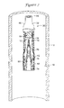
- FIG. 2 is a partial cross-sectional view of a magnetic retrieval device in accordance with an illustrative embodiment of the present invention
- FIG. 3 is another partial cross-sectional view of the magnetic retrieval device of FIG. 2 , showing the device in a second position.
- FIG. 4 is a partial cross-sectional view showing the intravascular filter of FIG. 1 disposed within a blood vessel;
- FIG. 5 is a partial cross-sectional view showing the magnetic retrieval device inserted within the blood vessel of FIG. 4 ;
- FIG. 6 is a partial cross-sectional view showing the magnetic retrieval device in a second position within the blood vessel of FIG. 4 , wherein the magnetic element is shown advanced towards the apical head of the intravascular filter;
- FIG. 7 is a partial cross-sectional view showing the magnetic retrieval device in a third position within the blood vessel of FIG. 4 , wherein the intravascular filter is shown fully retracted within the magnetic retrieval device;
- FIG. 8 is a partial cross-sectional view showing a magnetic retrieval device in accordance with another illustrative embodiment of the present invention.
- FIG. 9 is a partial cross-sectional view showing the magnetic retrieval device of FIG. 8 advanced to the site of an implanted intravascular filter;
- FIG. 10 is a partial cross-sectional view showing the magnetic retrieval device and intravascular filter of FIG. 9 , wherein the intravascular filter is shown in a first position disposed within the magnetic retrieval device;
- FIG. 11 is a partial cross-sectional view showing the magnetic retrieval device intravascular filter of FIG. 9 , wherein the intravascular filter is shown in a second position disposed within the magnetic retrieval device;
- FIG. 12 is a partial cross-sectional view showing the magnetic retrieval device and intravascular filter of FIG. 9 , wherein the intravascular filter is shown in a third position fully retracted within the magnetic retrieval device;
- FIG. 13 is a partial cross-sectional view showing a magnetic retrieval device in accordance with another illustrative embodiment of the present invention employing a locking mechanism
- FIG. 14 is a partial cross-sectional view showing a magnetic retrieval device in accordance with another illustrative embodiment of the present invention employing a locking mechanism
- FIG. 15 is a partial cross-sectional view showing a number of magnetic centering rings disposed within a blood vessel.
- FIG. 1 is a perspective view of a magnetically retrievable intravascular filter 10 in accordance with an illustrative embodiment of the present invention.
- Intravascular filter 10 illustratively a vena cava filter, includes an apical head 12 , and a plurality of elongated filter legs 14 each having a proximal section 16 and a distal section 18 .
- Each of the filter legs 14 may be configured identically with respect to each other, and may be symmetrically spaced about a central longitudinal axis L in a generally conical-shaped configuration when expanded.
- the filter legs 14 may be collectively arranged about the longitudinal axis L such that the proximal section 16 of each filter leg 14 converges at the apical head 12 to form an apex.
- the filter legs 14 may be biased to expand from a substantially straight position when radially constrained within a delivery device to an outswept position when deployed in a blood vessel.
- the filter legs 14 can be formed from a metal such as platinum, gold, tantalum, tungsten, titanium, or a metal alloy such as stainless steel (e.g. type 316L), Beta III Titanium, cobalt-chrome alloy, Elgiloy, L605, MP35N, Ta-10W, 17-4PH, or Aeromet 100.
- Metallic glasses such as Vitreloy 1 or Vitreloy 105 including extrinsic metal, ceramic, and/or nanoceramic fibers or particles can also be used.
- the filter legs 14 can be formed from a shape-memory material such as nickel-titanium alloy (Nitinol).
- a slight outward bend can be imparted to each filter leg 14 by heating the alloy beyond its final austenitic temperature, and then bending each filter leg 14 to a pre-defined shape.
- the filter legs 14 can be configured to revert to their pre-defined (i.e. bent) shape at or near body temperature (37° C.), allowing each individual filter leg 14 to maintain a straight position until deployed in the blood vessel.
- one or more bend regions 20 can be formed on each of the filter legs 14 to increase the total surface area of the intravascular filter 10 .
- the filter legs 14 can include an anti-thrombogenic coating such as herapin (or its derivatives), urokinase, or PPack (dextrophenylalanine proline arginine chloromethylketone) to prevent insertion site thrombosis.
- an anti-thrombogenic coating such as herapin (or its derivatives), urokinase, or PPack (dextrophenylalanine proline arginine chloromethylketone) to prevent insertion site thrombosis.
- each filter leg 14 may be configured to extend outwardly away from the apical head 12 to permit the intravascular filter 10 to be anchored along the inner wall of a blood vessel.
- the distal section 18 of each filter leg 14 may include an anchoring member 22 such as a needle, hook, barb, prong, or wedge configured to pierce the inner wall of the vessel and prevent migration of the intravascular filter 10 within the body.
- each anchoring member 22 compresses against the inner wall of the blood vessel as a result of the outwardly directed force exerted by the filter legs 14 .
- the apical head 12 may include a magnetic element 24 that can be used to magnetically center and retrieve the intravascular filter 10 using a magnetic retrieval device.
- the magnetic element 24 may include a bar magnet, magnetic ring, solenoid, or other suitable magnetic component incorporated into or otherwise forming the apical head 12 .
- the magnetic element 24 can be configured to produce a magnetic field having a south pole and a north pole, corresponding, respectively, to a proximal end 26 and distal end 28 of the apical head 12 .
- the formation of the magnetic field at the apical head 12 allows the intravascular filter 10 to be centered and retrieved within the blood vessel.
- the magnetic element 24 may comprise a magnetic material having a magnetic flux density sufficient to attract or repel a similarly configured magnetic element on the magnetic retrieval device.
- suitable metallic magnetic materials may include Iron (Fe), Nickel (Ni), Cobalt (Co), Magnetite (Fe 3 O 4 ), Neodymium-Iron-Boron (NdFeB), Aluminum-Nickel-Cobalt (AlNiCo), Samarium-Cob alt (SmCo), Awaruite (Ni 3 F), Wairauite (CoFe), and alloys or composites thereof.
- the magnetic element 24 is not limited to such materials.
- non-metallic materials such as vanadium-tetracyanoethylene, or thin-film polymeric materials such as thin film V[TCNE] x could be employed.
- the magnetic element 24 can be configured to produce a magnetic field on either a continual basis or at discrete time intervals during the intravascular procedure.
- the particular characteristics of the magnetic element 24 will depend in part on the type of magnetic material(s) employed, the size and temperature of the magnetic element 24 , the characteristics of the blood vessel and blood surrounding the magnetic element 24 , and the magnetic properties of the magnetic retrieval device.
- a ferromagnetic or ferrimagnetic material can be utilized to produce a spontaneous magnetic field at the apical head 12 .
- the strength of the magnetic field produced can be controlled by selecting a material having a desired magnetic flux density and/or by controlling various physical parameters of the magnet element 24 .
- the Curie temperature (T c ) can be set at or about body temperature to permit the magnetic element 24 to normally function within the body without magnetizing.
- T c Curie temperature
- a chilled saline solution can be delivered to the site of the magnetic element 24 , causing the material to regain its magnetization characteristics and thus allowing the intravascular filter 10 to be magnetically retrieved.
- the magnetic element 24 can also be formed from materials having a high Remanence and a Currie temperature above that of body temperature.
- the magnetic element 24 may comprise a paramagnetic material that becomes magnetized in response to an external magnetic field produced by the magnetic retrieval device. Unlike ferromagnetic/ferrimagnetic materials, paramagnetic materials do not exhibit a strong parallel atomic alignment in the absence of an external magnetic field. This property of the material may be useful in certain applications where continuous magnetization of the apical head 12 may interfere with the function and/or visualization of other devices inserted within the body, or where magnetization of the body is contraindicated.
- magnetic retrieval device 30 includes an elongated sheath 32 having a proximal section 34 and a distal section 36 .
- the proximal section 34 of sheath 32 may include a number of gripping fins 38 that can be used to manipulate the magnetic retrieval device 30 from a location outside of the patient's body.
- a locking hub 40 disposed on the proximal section 34 of the sheath 32 may be provided to lock the positioning of the sheath 32 within the vasculature, if desired.
- the sheath 32 may further define an interior lumen 42 configured to receive an intravascular device therein.
- the interior lumen 42 may extend through all or a portion of the sheath 32 , terminating distally at a distal end 44 of the sheath 32 .
- the sheath 32 may transition from a relatively low profile along the proximal section 34 of the sheath 32 to a larger profile along the distal section 36 to accommodate the collapsed intravascular device within the interior lumen 42 . Such transition may occur, for example, at a flared region 46 of the sheath 32 , wherein the profile of the sheath 32 expands slightly.
- the magnetic retrieval device 30 may include a braid 48 or other suitable reinforcement member disposed within the tubular wall 50 of the sheath 32 .
- the braid 48 may include a number of filaments 52 encased within or disposed adjacent to the tubular wall 50 .
- the filaments 52 may be arranged generally in two sets of parallel helices wound in opposite directions about a common longitudinal axis that extends through the center of the magnetic retrieval device 30 .
- the filaments 52 may intersect each other in an overlapping or interwoven fashion to permit the distal section 36 to radially expand when subjected to a compressive force.
- the braid 48 extends along the entire length of the distal section 36 , terminating proximally at or near the flared region 46 . In other embodiments, however, the braid 48 may extend along only a portion of the distal section 36 , or may extend further into all or a portion of the proximal section 34 .
- the magnetic retrieval device 30 may further include a magnetic retrieval mechanism 54 slidably disposed within the interior lumen 42 of the sheath 32 .
- the magnetic retrieval mechanism 54 may include an elongated member 56 such as a wire or tube having a proximal section 58 and a distal section 60 .
- the elongated member 56 may extend through all or a portion of the interior lumen 42 of the sheath 32 , terminating proximally at a location outside of the body. In the illustrative embodiment of FIG. 2 , for example, the elongated member 56 extends through the entire length of the magnetic retrieval device 30 , terminating proximally at a location proximal to the hub 40 .
- the elongated member 56 may extend through only a portion of the interior lumen 42 , exiting the sheath 32 through an exit port formed in the tubular wall 50 .
- the elongated member 56 can be configured to slide and/or rotate within the interior lumen 42 of the sheath 32 by manipulating the proximal section 58 in an appropriate manner.
- a flared region 62 of the elongated member 56 transforms the profile of the elongated member 56 from a relatively small profile along the proximal section 58 to a relatively large profile along the distal section 60 thereof.
- the distal section 60 of the elongated member 56 may further include a magnetic element 64 adapted to magnetically center and retrieve an intravascular device within the interior lumen 42 of the sheath 32 .
- the magnetic element 64 may be configured similar to the magnetic element 24 described above with respect to FIG. 1 , producing a magnetic field that can be used to magnetically attract the apical head 12 of the intravascular filter 10 .
- the magnetic element 64 may comprise a bar magnet that produces a magnetic field having a south pole and a north pole corresponding, respectively, to a proximal end 66 and distal end 68 of the magnetic element 64 .
- the magnetic element 64 may be attached to or formed integrally with the distal section 60 of the elongated wire 56 .
- the magnetic element 64 may be attached to the elongated wire 56 via a butt joint 70 .
- the outer wall 72 of the elongated member 56 may have an outer diameter that is smaller than the inner diameter of the sheath inner wall 74 .
- a thin lubricious layer or coating 76 may formed about the elongated member 56 and magnetic element 64 .
- a number of electromagnetic elements 78 disposed within the tubular wall 50 of the elongated sheath 12 can also be utilized to electromagnetically center and retrieve the intravascular device in conjunction with, or in lieu of, the magnetic element 64 of the elongated member 56 .
- the electromagnetic elements 78 can be positioned within the distal section 36 of the elongated sheath 12 at a location adjacent to the magnetic element 64 such that, when energized via a number of electrical leads (not shown), a magnetic field is produced at the distal section 36 .
- the electromagnetic elements 78 can be spaced apart from each other at equidistant intervals, as shown in FIG. 2 , or can be spaced apart from each at various intervals.
- a number of wires 80 coupled to the elongated member 56 and sheath 32 can be configured to expand from a radially collapsed position to a radially enlarged position.
- Each wire 80 may extend from a first end 82 coupled to the elongated member 56 to a second end 84 coupled to the distal end 44 of the sheath 32 .
- a number of openings 86 formed through the tubular wall 50 of the sheath 32 can be dimensioned to permit the wires 80 to expand outwardly when the elongated member 56 is moved relative to the sheath 32 .
- the elongated member 56 In a generally collapsed position illustrated in FIG. 2 , the elongated member 56 is disposed relative to the sheath 32 such that the magnetic element 64 is located proximally of the distal end 44 . In this position, the wires 80 are disposed tightly against the outer surface of the sheath 32 to facilitate advancement of the magnetic retrieval device 30 through the vasculature. As can be seen in FIG. 3 , however, the elongated member 56 can be advanced distally within the interior lumen 42 of the sheath 32 , causing the wires 80 to radially expand to a second position to engage the vessel wall.
- FIGS. 4-7 are partial cross-sectional views showing an illustrative method of using the magnetic retrieval device 30 of FIG. 2 to retrieve the intravascular filter 10 of FIG. 1 within a blood vessel.
- intravascular filter 10 In a first position depicted in FIG. 4 , intravascular filter 10 is shown deployed in an offset or tilted position within a blood vessel V. In this position, the apical head 12 of the intravascular filter 10 is misaligned with the central longitudinal axis of the blood vessel V. This misalignment can, in certain circumstances, make retrieval of the intravascular filter 10 using conventional retrieval devices more difficult since the physician must first align the retrieval device with the apical head 12 before the intravascular filter 10 can be collapsed therein.
- the magnetic retrieval device 30 can be inserted percutaneously into the body, and advanced to a position adjacent to the apical head 12 , as shown, for example, in FIG. 5 . Insertion of the magnetic retrieval device 30 within the vasculature may be accomplished through either a femoral artery or jugular vein, depending on the orientation of the apical head 12 within the body. In the illustrative view depicted in FIG. 5 , for example, the magnetic retrieval device 30 is shown inserted within a relatively large blood vessel (e.g. the inferior vena cava) via a jugular approach from a position above the implanted intravascular filter 10 .
- a relatively large blood vessel e.g. the inferior vena cava
- the magnetic retrieval device 30 can then be advanced through the body to the site of the intravascular filter 10 .
- a separate guide catheter and/or guidewire may be employed, consistent with standard practice in the art.
- the physician may next advance the elongated member 56 distally towards the apical head 12 while holding the sheath 32 stationary, as shown, for example, in FIG. 6 .
- advancement of the elongated member 56 in this manner causes the wires 80 to expand and engage the wall W of the blood vessel V, centering the magnetic retrieval device 30 within the blood vessel V.
- Advancement of the elongated member 56 in this manner also forces the magnetic element 64 into close proximity with the magnetic element 24 of the intravascular filter 10 .
- the opposite polarities of the magnetic elements 24 , 64 act to attract the apical head 12 towards the elongated member 56 , magnetically coupling the two elements 24 , 64 together.
- the physician next retracts the elongated member 56 proximally, causing the intravascular filter 10 to detach from the vessel wall and retract into the interior lumen 42 of the sheath 32 , as shown, for example, in FIG. 7 .
- an optional step of energizing the electromagnetic elements 78 can also be performed to increase the magnetic attraction force of the magnetic element 64 .
- the flared region 46 of the sheath 32 can be configured to engage the flared region 62 (see FIG.
- the magnetic retrieval device 30 can then be withdrawn to remove the intravascular filter 10 from the body.
- FIG. 8 is a partial cross-sectional view showing a magnetic retrieval device 88 in accordance with another illustrative embodiment of the present invention employing one or more electromagnetic elements.
- Magnetic retrieval device 88 includes an elongated sheath 90 having a proximal section 92 , a distal section 94 , and an interior lumen 96 at least in part therethrough configured to receive an intravascular device.
- the proximal section 92 of the sheath 90 may include a number of gripping fins 98 that can be used to manipulate the device from a location outside of the patient's body.
- a locking hub 100 disposed on the proximal section 92 of the sheath 90 may also be provided to lock the positioning of the sheath 90 along a guiding member such as a guidewire or guide catheter.
- the sheath 90 may include a braid 102 or other suitable reinforcement means to provide additional axial and torsional rigidity to the magnetic retrieval device 88 .
- the braid 102 may include a number of filaments 104 encased within or disposed adjacent to a tubular wall 106 of the sheath 90 . Similar to the filaments 52 described above, the filaments 104 can be provided along all or a portion of the sheath 90 , and can be configured to radially expand when subjected to a compressive force.
- a flared region 108 of the sheath 90 may also be provided to transition the sheath 90 from a relatively small profile along the proximal section 92 to a larger profile along the distal section 94 to accommodate the collapsed intravascular device within the interior lumen 96 .
- the magnetic retrieval device 88 may further include a number of electromagnetic elements 110 , 112 , 114 , 116 , 118 , 120 configured to electromagnetically center and retrieve the intravascular device.
- the electromagnetic elements 110 , 112 , 114 , 116 , 118 , 120 can be spaced apart from each other at variable intervals beginning with a first electromagnetic element 110 disposed at or near the distal end 122 of the sheath 90 , and then extending proximally to a second electromagnetic element 112 , a third electromagnetic element 114 , and so forth.
- the spacing between each electromagnetic element 110 , 112 , 114 , 116 , 118 , 120 can decrease in the proximal direction along the sheath 90 to provide a greater magnetic field strength as the intravascular device is loaded further into the interior lumen 96 of the sheath 90 .
- the electromagnetic elements 110 , 112 , 114 , 116 , 118 , 120 may each comprise a magnetic ring or solenoid that can be used to produce a magnetic field when energized via a number of electrodes (not shown) disposed within the tubular wall 106 .
- the electrode leads can be electrically connected to an electrical source located outside of the patient's body, which can be activated to deliver a current that can be used to induce a magnetic field.
- the electromagnetic elements 110 , 112 , 114 , 116 , 118 , 120 can each be selectively activated all at once, or at different intervals, to center and retrieve the intravascular device.
- the electromagnetic elements 110 , 112 , 114 , 116 , 118 , 120 can be activated in cascading fashion beginning with the first electromagnetic element 110 , and then activating each successive electromagnetic element as the intravascular device is further retrieved into the interior lumen 96 of the sheath 90 .
- FIG. 8 While six electromagnetic elements are specifically illustrated in FIG. 8 , it should be understood that a greater or lesser number of electromagnetic elements could be employed, if desired. Moreover, while the electromagnetic elements illustrated in FIG. 8 are spaced apart from each other with increasing concentration in the proximal direction, the electromagnetic elements may be arranged in some other desired fashion. In certain embodiments, for example, the electromagnetic elements can be arranged at equidistant intervals, similar to the illustrative magnetic retrieval device 30 of FIG. 2 .
- magnetic retrieval device 88 is shown advanced within a blood vessel V to a location adjacent to an implanted intravascular device (e.g. intravascular filter 10 ).
- an implanted intravascular device e.g. intravascular filter 10
- one or more of the electromagnetic elements can then activated, inducing a magnetic field at the distal section 94 of the sheath 90 having a strength sufficient to detach the intravascular filter 10 from the vessel wall W.
- the activation of one or more of the electromagnetic elements produces a magnetic field 124 (represented generally by dashed lines) that causes the magnetic element 24 of the apical head 12 to align with the central longitudinal axis of the magnetic retrieval device 88 and retract into the interior lumen 96 of the sheath 90 .
- the activation of the other electromagnetic elements 112 , 114 , 116 , 118 , 120 can be configured to further drawn the intravascular filter 10 into the interior lumen 96 of the sheath 90 .
- the intravascular filter 10 is shown further retracted into the interior lumen 96 , with the apical head 12 being advanced to a subsequent position located proximally of the second electromagnetic element 112 .
- the flow of current delivered to the first electromagnetic element 110 can be reversed, inducing a magnetic field that can be used to repel the apical head 12 further proximally into the interior lumen 96 of the sheath 80 .
- FIG. 13 is a partial cross-sectional view showing a magnetic retrieval device 126 in accordance with another illustrative embodiment of the present invention employing a locking mechanism.
- Magnetic retrieval device 126 includes an elongated sheath 128 having a proximal section 130 , a distal section 132 , and an interior lumen 134 at least in part therethrough configured to receive an intravascular device such as intravascular filter 10 .
- the proximal section 130 of the sheath 128 may include a number of gripping fins 136 that can be used to manipulate the magnetic retrieval device 126 from a location outside of the patient's body.
- Other features such as a locking hub 138 may also be provided, if desired.
- the magnetic retrieval device 126 may further include an inner tubular member 140 configured to lock onto the apical head 12 of the intravascular filter 10 .
- the inner tubular member 140 can be dimensioned to slide and rotate within the interior lumen 134 of the sheath 128 , allowing a distal end 142 of the inner tubular member 140 to be advanced distally beyond the distal end 144 of the sheath 128 during retrieval.
- the inner tubular member 140 may define an interior lumen 146 adapted to slidably receive the apical head 12 of the intravascular filter 10 .
- An internal projection 148 extending inwardly within the interior lumen 146 forms a locking mechanism that can be used to secure the apical head 12 to the inner tubular member 140 .
- the internal projection 148 may include a sloping portion 150 , a constant diameter portion 152 , and a shoulder portion 154 .
- the sloping and constant diameter portions 150 , 152 can be configured flex or bend slightly to permit the apical head 12 to move within the interior lumen 146 in only the proximal direction, as indicated generally by the arrow 156 .
- the shoulder portion 154 can be configured to engage the proximal end 28 of the apical head 12 , thereby securing the intravascular filter 10 to the magnetic retrieval device 126 .
- a magnetic element 158 slidably disposed within the interior lumen 146 can be advanced to a location adjacent to the shoulder 154 .
- the magnetic element 158 can be configured to produce a magnetic field having a polarity opposite that of the magnetic element 24 , causing apical head 12 to be drawn proximally within the interior lumen 146 beyond the internal projection 148 .
- a number of electromagnetic elements 160 disposed within the sheath 128 can also be utilized to magnetically attract the magnetic element 24 , causing it to move proximally within the interior lumen 146 .
- the intravascular filter 10 can then be withdrawn into the interior lumen 134 of the sheath 128 by advancing the sheath 128 distally while holding the inner tubular member 140 stationary, or alternatively, by advancing the inner tubular member 140 proximally while holding the sheath 128 stationary.
- the magnetic retrieval device 126 and accompanying intravascular filter 10 can then be removed from the body, if desired.
- FIG. 14 is a partial cross-sectional view showing a magnetic retrieval device 162 in accordance with another illustrative embodiment of the present invention employing a locking mechanism.
- Magnetic retrieval device 162 includes an elongated sheath 164 having a proximal section 166 , a distal section 168 , and an interior lumen 170 at least in part therethrough configured to receive an intravascular device such as intravascular filter 10 .
- the proximal section 166 of the sheath 164 may include a number of gripping fins 168 that can be used to manipulate the magnetic retrieval device 162 from a location outside of the patient's body, and a locking hub 169 to lock the magnetic retrieval device 162 to a guiding member such as a guidewire.
- a number of inwardly projecting fingers 172 extending into the interior lumen 170 of the sheath 164 can be configured to lock to the apical head 12 of the intravascular filter 10 during retrieval.
- the inwardly projecting fingers 172 can be configured to displace and permit movement of the apical head 12 only in response to movement in the direction indicated generally by arrow 174 .
- Retrieval of the intravascular filter 10 can be accomplished in a manner similar to that described herein.
- One or more electromagnetic elements 176 disposed within the distal section 168 of the sheath 164 can be configured to produce a magnetic field that magnetically attracts the intravascular filter 10 into the interior lumen 170 of the sheath 64 .
- each of the inwardly projecting fingers 172 can be configured to displace to permit the intravascular filter 10 to be secured further within the interior lumen 170 of the sheath 164 .
- the magnetic retrieval device 162 and accompanying intravascular filter 10 can then be removed from the body, if desired.
- FIG. 15 is a partial cross-sectional view showing a magnetic centering device 178 for use in centering an intravascular device (e.g. intravascular filter 10 ) within a blood vessel V.
- the magnetic centering device 178 can comprise an outer magnetic ring 180 that can be placed about the outer wall of the blood vessel V, and an optional inner magnetic ring 182 that can be expanded and supported within the interior of the blood vessel V.
- the inner and outer magnetic rings 180 , 182 can both be configured for either permanent or temporary insertion within the blood vessel V.
- a number of anchoring members 184 are shown disposed about the outer periphery of the inner magnetic ring 182 to aid in securing the inner magnetic ring 182 to the internal wall W of the blood vessel V.
- the outer magnetic ring 182 can be configured to produce a magnetic field within the blood vessel V that can be used to repel the magnetic element 24 of the apical head 12 towards the center of the blood vessel V.
- the outer magnetic ring 182 may comprise an electromagnetic element such as a solenoid that can be energized to produce a first magnetic field 186 within the blood vessel V.
- the inner magnetic centering ring 182 in turn, can comprise a paramagnetic element that, when energized via a charge from the outer magnetic centering ring 180 , produces a second magnetic field 188 within the blood vessel V.
- the outer and inner magnetic rings 180 , 182 When energized in this manner, the outer and inner magnetic rings 180 , 182 combine to produce a magnetic dipole having a north pole 190 and south pole 192 .
- the magnetic element 24 of the apical head 12 in turn, can have a north pole 194 and south pole 196 configuration that is opposite of that produced by the outer and inner magnetic rings 180 , 182 .
- An illustrative method of centering the intravascular filter 10 using the magnetic centering device 178 may include the steps of implanting the outer and inner magnetic rings 180 , 182 at a target location of the blood vessel V, advancing the intravascular filter 10 to a position such that the apical head 12 is located proximal the interior 198 of the inner magnetic centering ring 182 , and then deploying the intravascular filter 10 within the blood vessel V.
- the repulsive force produced by the magnetic rings 180 , 182 causes the apical head 12 to align centrally within the interior 198 of the inner magnetic centering ring 182 , preventing the intravascular filter 10 from becoming tilted or offset within the blood vessel V.
Abstract
Description
Claims (18)
Priority Applications (8)
| Application Number | Priority Date | Filing Date | Title |
|---|---|---|---|
| US10/838,988 US7799050B2 (en) | 2004-05-05 | 2004-05-05 | Devices and methods for magnetically manipulating intravascular devices |
| CA002566009A CA2566009A1 (en) | 2004-05-05 | 2005-05-05 | Devices and methods for magnetically manipulating intravasular devices |
| JP2007511636A JP4814874B2 (en) | 2004-05-05 | 2005-05-05 | Instrument and method for magnetically manipulating endovascular instruments |
| EP11193587A EP2433589A1 (en) | 2004-05-05 | 2005-05-05 | Devices and methods for magnetically manipulating intravascular devices |
| DK05742064.8T DK1761222T3 (en) | 2004-05-05 | 2005-05-05 | DEVICES AND METHODS FOR MAGNETIC MANIPULATION OF INTRAVASCULAR DEVICES |
| ES05742064T ES2400569T3 (en) | 2004-05-05 | 2005-05-05 | Devices and methods for magnetically manipulating intravascular devices |
| PCT/US2005/015849 WO2005107639A2 (en) | 2004-05-05 | 2005-05-05 | Devices and methods for magnetically manipulating intravasular devices |
| EP05742064A EP1761222B1 (en) | 2004-05-05 | 2005-05-05 | Devices and methods for magnetically manipulating intravascular devices |
Applications Claiming Priority (1)
| Application Number | Priority Date | Filing Date | Title |
|---|---|---|---|
| US10/838,988 US7799050B2 (en) | 2004-05-05 | 2004-05-05 | Devices and methods for magnetically manipulating intravascular devices |
Publications (2)
| Publication Number | Publication Date |
|---|---|
| US20050251197A1 US20050251197A1 (en) | 2005-11-10 |
| US7799050B2 true US7799050B2 (en) | 2010-09-21 |
Family
ID=34967826
Family Applications (1)
| Application Number | Title | Priority Date | Filing Date |
|---|---|---|---|
| US10/838,988 Expired - Fee Related US7799050B2 (en) | 2004-05-05 | 2004-05-05 | Devices and methods for magnetically manipulating intravascular devices |
Country Status (7)
| Country | Link |
|---|---|
| US (1) | US7799050B2 (en) |
| EP (2) | EP2433589A1 (en) |
| JP (1) | JP4814874B2 (en) |
| CA (1) | CA2566009A1 (en) |
| DK (1) | DK1761222T3 (en) |
| ES (1) | ES2400569T3 (en) |
| WO (1) | WO2005107639A2 (en) |
Cited By (17)
| Publication number | Priority date | Publication date | Assignee | Title |
|---|---|---|---|---|
| US20070250070A1 (en) * | 2006-04-24 | 2007-10-25 | Nobis Rudolph H | Medical instrument having a medical snare |
| US20070249908A1 (en) * | 2006-04-24 | 2007-10-25 | Ifung Lu | Medical cannula and medical cannula system |
| US20070270639A1 (en) * | 2006-05-17 | 2007-11-22 | Long Gary L | Medical instrument having a catheter and having a catheter accessory device and method for using |
| US20080281403A1 (en) * | 2004-05-25 | 2008-11-13 | William Cook Europe Aps | Stent and Stent Retrieval System and a Method of Pulling a Stent Into a Tubular Member |
| US7959642B2 (en) | 2006-05-16 | 2011-06-14 | Ethicon Endo-Surgery, Inc. | Medical instrument having a needle knife |
| US20120130418A1 (en) * | 2010-11-18 | 2012-05-24 | Boston Scientific Scimed, Inc. | Magnetically retrievable vena cava filter and retrieval device therefor |
| US8764769B1 (en) | 2013-03-12 | 2014-07-01 | Levita Magnetics International Corp. | Grasper with magnetically-controlled positioning |
| US8790245B2 (en) | 2009-02-06 | 2014-07-29 | Levita Magnetics International Corp. | Remote traction and guidance system for mini-invasive surgery |
| US9138250B2 (en) | 2006-04-24 | 2015-09-22 | Ethicon Endo-Surgery, Inc. | Medical instrument handle and medical instrument having a handle |
| US10010370B2 (en) | 2013-03-14 | 2018-07-03 | Levita Magnetics International Corp. | Magnetic control assemblies and systems therefor |
| US10537348B2 (en) | 2014-01-21 | 2020-01-21 | Levita Magnetics International Corp. | Laparoscopic graspers and systems therefor |
| US10898192B2 (en) | 2017-06-15 | 2021-01-26 | Roberto Tapia Espriu | Adjustable pressure surgical clamp with releasable or integrated remote manipulator for laparoscopies |
| US10905511B2 (en) | 2015-04-13 | 2021-02-02 | Levita Magnetics International Corp. | Grasper with magnetically-controlled positioning |
| US11020137B2 (en) | 2017-03-20 | 2021-06-01 | Levita Magnetics International Corp. | Directable traction systems and methods |
| US11413026B2 (en) | 2007-11-26 | 2022-08-16 | Attractive Surgical, Llc | Magnaretractor system and method |
| US11484377B2 (en) | 2018-11-02 | 2022-11-01 | Grey Matter Medical Products | Rail tension extraction devices |
| US11583354B2 (en) | 2015-04-13 | 2023-02-21 | Levita Magnetics International Corp. | Retractor systems, devices, and methods for use |
Families Citing this family (22)
| Publication number | Priority date | Publication date | Assignee | Title |
|---|---|---|---|---|
| US7794472B2 (en) * | 2004-08-11 | 2010-09-14 | Boston Scientific Scimed, Inc. | Single wire intravascular filter |
| US8025668B2 (en) * | 2005-04-28 | 2011-09-27 | C. R. Bard, Inc. | Medical device removal system |
| US9480589B2 (en) * | 2005-05-13 | 2016-11-01 | Boston Scientific Scimed, Inc. | Endoprosthesis delivery system |
| US8795351B2 (en) | 2007-04-13 | 2014-08-05 | C.R. Bard, Inc. | Migration resistant embolic filter |
| JP4548801B2 (en) * | 2007-07-31 | 2010-09-22 | フィルメック株式会社 | Medical treatment tool for filter recovery |
| US20100228281A1 (en) * | 2009-01-16 | 2010-09-09 | Paul Gilson | Vascular filter system |
| FR2950798B1 (en) * | 2009-10-06 | 2012-12-28 | Braun Medical Sas | SAFETY CARTRIDGE FOR A RETIRABLE CELL FILTER |
| US20120089173A1 (en) * | 2010-10-07 | 2012-04-12 | Cook Incorporated | Filter with magnetic tip for clot fragmentation |
| US9414752B2 (en) | 2012-11-09 | 2016-08-16 | Elwha Llc | Embolism deflector |
| EP3666227A1 (en) | 2013-06-14 | 2020-06-17 | Avantec Vascular Corporation | Inferior vena cava filter and retrieval systems |
| JP6775507B2 (en) | 2014-12-12 | 2020-10-28 | アバンテック バスキュラー コーポレイション | IVC recovery system with intervening support members |
| US10028820B2 (en) * | 2015-04-14 | 2018-07-24 | Cook Medical Technologies Llc | Carotid artery blood filter plugging alarm |
| WO2017100563A1 (en) * | 2015-12-10 | 2017-06-15 | Avantec Vascular Corporation | Ivc filter retrieval system sheath improvements |
| BR112018072634A2 (en) * | 2016-05-03 | 2019-02-19 | Adient Medical, Inc. | method and device for implanting and retrieving objects in a cavity |
| CN110167482A (en) | 2016-12-22 | 2019-08-23 | 阿万泰血管公司 | The systems, devices and methods for being used to fetch system with tether |
| CN107374778A (en) * | 2017-09-12 | 2017-11-24 | 浙江归创医疗器械有限公司 | Vena cava filter and its retracting device |
| CN112584799A (en) | 2018-06-29 | 2021-03-30 | 阿万泰血管公司 | Systems and methods for implants and deployment devices |
| CN109223249A (en) * | 2018-10-29 | 2019-01-18 | 深圳市科奕顿生物医疗科技有限公司 | Implant recycles instrument and its application and packaging |
| US11253279B2 (en) * | 2018-11-15 | 2022-02-22 | Progressive NEURO, Inc. | Apparatus, system, and method for vasculature obstruction removal |
| US20220047286A1 (en) * | 2020-08-11 | 2022-02-17 | Myodynamics, LLC | Medical device for snaring guidewire |
| CN113951982B (en) * | 2021-11-25 | 2023-07-14 | 郑州大学第一附属医院 | Inferior vena cava thrombus filter convenient for thrombus ablation |
| CN117084823A (en) * | 2023-08-14 | 2023-11-21 | 上海心玮医疗科技股份有限公司 | Embolic protection device |
Citations (40)
| Publication number | Priority date | Publication date | Assignee | Title |
|---|---|---|---|---|
| US4619246A (en) * | 1984-05-23 | 1986-10-28 | William Cook, Europe A/S | Collapsible filter basket |
| US4865030A (en) * | 1987-01-21 | 1989-09-12 | American Medical Systems, Inc. | Apparatus for removal of objects from body passages |
| US5324304A (en) * | 1992-06-18 | 1994-06-28 | William Cook Europe A/S | Introduction catheter set for a collapsible self-expandable implant |
| US5464023A (en) * | 1994-01-31 | 1995-11-07 | Cordis Corporation | Magnetic exchange device for catheters |
| US5570701A (en) * | 1992-08-12 | 1996-11-05 | Scimed Life Systems, Inc. | Shaft movement control apparatus and method |
| US5658302A (en) * | 1995-06-07 | 1997-08-19 | Baxter International Inc. | Method and device for endoluminal disruption of venous valves |
| US5814064A (en) | 1997-03-06 | 1998-09-29 | Scimed Life Systems, Inc. | Distal protection device |
| US5827324A (en) | 1997-03-06 | 1998-10-27 | Scimed Life Systems, Inc. | Distal protection device |
| US5848964A (en) * | 1997-06-06 | 1998-12-15 | Samuels; Shaun Lawrence Wilkie | Temporary inflatable filter device and method of use |
| US5910154A (en) | 1997-05-08 | 1999-06-08 | Embol-X, Inc. | Percutaneous catheter and guidewire having filter and medical device deployment |
| US5928261A (en) * | 1998-06-29 | 1999-07-27 | Ruiz; Carlos E. | Removable vascular filter, catheter system and methods of use |
| US5941896A (en) | 1997-09-08 | 1999-08-24 | Montefiore Hospital And Medical Center | Filter and method for trapping emboli during endovascular procedures |
| US5984947A (en) | 1998-05-04 | 1999-11-16 | Scimed Life Systems, Inc. | Removable thrombus filter |
| US5989281A (en) | 1995-11-07 | 1999-11-23 | Embol-X, Inc. | Cannula with associated filter and methods of use during cardiac surgery |
| US6013038A (en) * | 1995-01-10 | 2000-01-11 | Advanced Cardiovascular Systems, Inc. | Magnetic guidewire anchoring apparatus and method for facilitating exchange of an over-the-wire catheter |
| US6059814A (en) | 1997-06-02 | 2000-05-09 | Medtronic Ave., Inc. | Filter for filtering fluid in a bodily passageway |
| US6079413A (en) * | 1994-06-17 | 2000-06-27 | Trudell Medical Limited | Catheter system for delivery of aerosolized medicine for use with pressurized propellant canister |
| US6142987A (en) | 1999-08-03 | 2000-11-07 | Scimed Life Systems, Inc. | Guided filter with support wire and methods of use |
| US6152946A (en) | 1998-03-05 | 2000-11-28 | Scimed Life Systems, Inc. | Distal protection device and method |
| US6179859B1 (en) | 1999-07-16 | 2001-01-30 | Baff Llc | Emboli filtration system and methods of use |
| US6217600B1 (en) | 2000-01-26 | 2001-04-17 | Scimed Life Systems, Inc. | Thrombus filter with break-away anchor members |
| US6264672B1 (en) | 1999-10-25 | 2001-07-24 | Biopsy Sciences, Llc | Emboli capturing device |
| US6277139B1 (en) | 1999-04-01 | 2001-08-21 | Scion Cardio-Vascular, Inc. | Vascular protection and embolic material retriever |
| US6277138B1 (en) | 1999-08-17 | 2001-08-21 | Scion Cardio-Vascular, Inc. | Filter for embolic material mounted on expandable frame |
| US6290710B1 (en) | 1999-12-29 | 2001-09-18 | Advanced Cardiovascular Systems, Inc. | Embolic protection device |
| US6336934B1 (en) | 1997-11-07 | 2002-01-08 | Salviac Limited | Embolic protection device |
| US6368338B1 (en) * | 1999-03-05 | 2002-04-09 | Board Of Regents, The University Of Texas | Occlusion method and apparatus |
| US6371971B1 (en) * | 1999-11-15 | 2002-04-16 | Scimed Life Systems, Inc. | Guidewire filter and methods of use |
| US6511497B1 (en) | 1999-09-14 | 2003-01-28 | Cormedics Gmbh | Vascular filter system |
| US6544276B1 (en) | 1996-05-20 | 2003-04-08 | Medtronic Ave. Inc. | Exchange method for emboli containment |
| US6558349B1 (en) * | 1992-03-02 | 2003-05-06 | Thomas R. Kirkman | Apparatus and method for retaining a catheter in a blood vessel in a fixed position |
| US6616680B1 (en) | 2000-11-01 | 2003-09-09 | Joseph M. Thielen | Distal protection and delivery system and method |
| US20030171770A1 (en) | 2002-03-08 | 2003-09-11 | Kusleika Richard S. | Distal protection devices having controllable wire motion |
| US6623450B1 (en) | 1999-12-17 | 2003-09-23 | Advanced Cardiovascular Systems, Inc. | System for blocking the passage of emboli through a body vessel |
| US20030187474A1 (en) | 1997-11-07 | 2003-10-02 | Martin Keegan | Embolic protection system |
| US6656199B1 (en) * | 2000-08-24 | 2003-12-02 | Scimed Life Systems, Inc. | Magnetic clamp assembly for an elongated flexible medical device |
| US6689119B1 (en) * | 2000-06-02 | 2004-02-10 | Scimed Life Systems, Inc. | Self-aligning medical device |
| US20040158274A1 (en) * | 2003-02-11 | 2004-08-12 | Scimed Life Systems, Inc. | Retrievable IVC filter |
| US7144408B2 (en) * | 2002-03-05 | 2006-12-05 | Salviac Limited | Embolic protection system |
| US7232462B2 (en) * | 2004-03-31 | 2007-06-19 | Cook Incorporated | Self centering delivery catheter |
Family Cites Families (7)
| Publication number | Priority date | Publication date | Assignee | Title |
|---|---|---|---|---|
| US6059614A (en) * | 1996-11-20 | 2000-05-09 | Lucent Technologies Inc. | Modular information and processing center |
| US6544278B1 (en) * | 1998-11-06 | 2003-04-08 | Scimed Life Systems, Inc. | Rolling membrane stent delivery system |
| US20020183762A1 (en) * | 2001-06-01 | 2002-12-05 | Ams Research Corporation | Bone anchor inserters and methods |
| WO2004019817A1 (en) * | 2002-08-27 | 2004-03-11 | Amir Belson | Embolic protection device |
| JP2005021576A (en) * | 2003-07-02 | 2005-01-27 | Pentax Corp | Endoscope magnetic anchor teleguiding system and endoscopic treatment method using magnetic anchor teleguiding system |
| JP4614263B2 (en) * | 2004-01-06 | 2011-01-19 | Hoya株式会社 | Gripping device |
| US20050240215A1 (en) * | 2004-04-21 | 2005-10-27 | Scimed Life Systems, Inc. | Magnetic embolic protection device and method |
-
2004
- 2004-05-05 US US10/838,988 patent/US7799050B2/en not_active Expired - Fee Related
-
2005
- 2005-05-05 JP JP2007511636A patent/JP4814874B2/en not_active Expired - Fee Related
- 2005-05-05 ES ES05742064T patent/ES2400569T3/en active Active
- 2005-05-05 EP EP11193587A patent/EP2433589A1/en not_active Withdrawn
- 2005-05-05 WO PCT/US2005/015849 patent/WO2005107639A2/en not_active Application Discontinuation
- 2005-05-05 CA CA002566009A patent/CA2566009A1/en not_active Abandoned
- 2005-05-05 EP EP05742064A patent/EP1761222B1/en not_active Not-in-force
- 2005-05-05 DK DK05742064.8T patent/DK1761222T3/en active
Patent Citations (43)
| Publication number | Priority date | Publication date | Assignee | Title |
|---|---|---|---|---|
| US4619246A (en) * | 1984-05-23 | 1986-10-28 | William Cook, Europe A/S | Collapsible filter basket |
| US4865030A (en) * | 1987-01-21 | 1989-09-12 | American Medical Systems, Inc. | Apparatus for removal of objects from body passages |
| US6558349B1 (en) * | 1992-03-02 | 2003-05-06 | Thomas R. Kirkman | Apparatus and method for retaining a catheter in a blood vessel in a fixed position |
| US5324304A (en) * | 1992-06-18 | 1994-06-28 | William Cook Europe A/S | Introduction catheter set for a collapsible self-expandable implant |
| US5570701A (en) * | 1992-08-12 | 1996-11-05 | Scimed Life Systems, Inc. | Shaft movement control apparatus and method |
| US5464023A (en) * | 1994-01-31 | 1995-11-07 | Cordis Corporation | Magnetic exchange device for catheters |
| US6079413A (en) * | 1994-06-17 | 2000-06-27 | Trudell Medical Limited | Catheter system for delivery of aerosolized medicine for use with pressurized propellant canister |
| US6013038A (en) * | 1995-01-10 | 2000-01-11 | Advanced Cardiovascular Systems, Inc. | Magnetic guidewire anchoring apparatus and method for facilitating exchange of an over-the-wire catheter |
| US5658302A (en) * | 1995-06-07 | 1997-08-19 | Baxter International Inc. | Method and device for endoluminal disruption of venous valves |
| US5989281A (en) | 1995-11-07 | 1999-11-23 | Embol-X, Inc. | Cannula with associated filter and methods of use during cardiac surgery |
| US6544276B1 (en) | 1996-05-20 | 2003-04-08 | Medtronic Ave. Inc. | Exchange method for emboli containment |
| US5814064A (en) | 1997-03-06 | 1998-09-29 | Scimed Life Systems, Inc. | Distal protection device |
| US5827324A (en) | 1997-03-06 | 1998-10-27 | Scimed Life Systems, Inc. | Distal protection device |
| US6001118A (en) | 1997-03-06 | 1999-12-14 | Scimed Life Systems, Inc. | Distal protection device and method |
| US5910154A (en) | 1997-05-08 | 1999-06-08 | Embol-X, Inc. | Percutaneous catheter and guidewire having filter and medical device deployment |
| US6059814A (en) | 1997-06-02 | 2000-05-09 | Medtronic Ave., Inc. | Filter for filtering fluid in a bodily passageway |
| US5848964A (en) * | 1997-06-06 | 1998-12-15 | Samuels; Shaun Lawrence Wilkie | Temporary inflatable filter device and method of use |
| US5941896A (en) | 1997-09-08 | 1999-08-24 | Montefiore Hospital And Medical Center | Filter and method for trapping emboli during endovascular procedures |
| US20030187474A1 (en) | 1997-11-07 | 2003-10-02 | Martin Keegan | Embolic protection system |
| US6336934B1 (en) | 1997-11-07 | 2002-01-08 | Salviac Limited | Embolic protection device |
| US6152946A (en) | 1998-03-05 | 2000-11-28 | Scimed Life Systems, Inc. | Distal protection device and method |
| US5984947A (en) | 1998-05-04 | 1999-11-16 | Scimed Life Systems, Inc. | Removable thrombus filter |
| US5928261A (en) * | 1998-06-29 | 1999-07-27 | Ruiz; Carlos E. | Removable vascular filter, catheter system and methods of use |
| US6368338B1 (en) * | 1999-03-05 | 2002-04-09 | Board Of Regents, The University Of Texas | Occlusion method and apparatus |
| US6277139B1 (en) | 1999-04-01 | 2001-08-21 | Scion Cardio-Vascular, Inc. | Vascular protection and embolic material retriever |
| US6179859B1 (en) | 1999-07-16 | 2001-01-30 | Baff Llc | Emboli filtration system and methods of use |
| US6142987A (en) | 1999-08-03 | 2000-11-07 | Scimed Life Systems, Inc. | Guided filter with support wire and methods of use |
| US6344049B1 (en) | 1999-08-17 | 2002-02-05 | Scion Cardio-Vascular, Inc. | Filter for embolic material mounted on expandable frame and associated deployment system |
| US6277138B1 (en) | 1999-08-17 | 2001-08-21 | Scion Cardio-Vascular, Inc. | Filter for embolic material mounted on expandable frame |
| US6511497B1 (en) | 1999-09-14 | 2003-01-28 | Cormedics Gmbh | Vascular filter system |
| US6264672B1 (en) | 1999-10-25 | 2001-07-24 | Biopsy Sciences, Llc | Emboli capturing device |
| US6371971B1 (en) * | 1999-11-15 | 2002-04-16 | Scimed Life Systems, Inc. | Guidewire filter and methods of use |
| US20020183782A1 (en) | 1999-11-15 | 2002-12-05 | Scimed Life Systems, Inc. | Guidewire filter and methods of use |
| US6623450B1 (en) | 1999-12-17 | 2003-09-23 | Advanced Cardiovascular Systems, Inc. | System for blocking the passage of emboli through a body vessel |
| US6290710B1 (en) | 1999-12-29 | 2001-09-18 | Advanced Cardiovascular Systems, Inc. | Embolic protection device |
| US6217600B1 (en) | 2000-01-26 | 2001-04-17 | Scimed Life Systems, Inc. | Thrombus filter with break-away anchor members |
| US6689119B1 (en) * | 2000-06-02 | 2004-02-10 | Scimed Life Systems, Inc. | Self-aligning medical device |
| US6656199B1 (en) * | 2000-08-24 | 2003-12-02 | Scimed Life Systems, Inc. | Magnetic clamp assembly for an elongated flexible medical device |
| US6616680B1 (en) | 2000-11-01 | 2003-09-09 | Joseph M. Thielen | Distal protection and delivery system and method |
| US7144408B2 (en) * | 2002-03-05 | 2006-12-05 | Salviac Limited | Embolic protection system |
| US20030171770A1 (en) | 2002-03-08 | 2003-09-11 | Kusleika Richard S. | Distal protection devices having controllable wire motion |
| US20040158274A1 (en) * | 2003-02-11 | 2004-08-12 | Scimed Life Systems, Inc. | Retrievable IVC filter |
| US7232462B2 (en) * | 2004-03-31 | 2007-06-19 | Cook Incorporated | Self centering delivery catheter |
Non-Patent Citations (4)
| Title |
|---|
| Classes of Magnetic Materials, Hitchhiker's Guide to Magnetism, http://www.geo.umn.edu/orgs/lrm/hg2m/hg2m-b/hg2m-b.html, Feb. 6, 2004, 10 pages. |
| Classes of Magnetic Materials, Hitchhiker's Guide to Magnetism, http://www.geo.umn.edu/orgs/lrm/hg2m/hg2m—b/hg2m—b.html, Feb. 6, 2004, 10 pages. |
| Pokhodnya et al., Thin Film V[TCNE], Magnets, Abstract, http://www.chem.utah.edu/chemistry/faculty/miller/abstracts/abstract18.htm, Mar. 4, 2004, 1 page. |
| UI Researchers Investigate the Use of Magnetic Treat Prostate Cancer, UI Health Care News: Week of Feb. 19, 2001, http://www.uihealthcare.com/news/news/2001/02/19prostatecancer.html, Jan. 22, 2004, 3 pages. |
Cited By (28)
| Publication number | Priority date | Publication date | Assignee | Title |
|---|---|---|---|---|
| US20080281403A1 (en) * | 2004-05-25 | 2008-11-13 | William Cook Europe Aps | Stent and Stent Retrieval System and a Method of Pulling a Stent Into a Tubular Member |
| US8343210B2 (en) * | 2004-05-25 | 2013-01-01 | Stenz Corporation | Stent and stent retrieval system and a method of pulling a stent into tubular member |
| US9138250B2 (en) | 2006-04-24 | 2015-09-22 | Ethicon Endo-Surgery, Inc. | Medical instrument handle and medical instrument having a handle |
| US20070249908A1 (en) * | 2006-04-24 | 2007-10-25 | Ifung Lu | Medical cannula and medical cannula system |
| US8211114B2 (en) | 2006-04-24 | 2012-07-03 | Ethicon Endo-Surgery, Inc. | Medical instrument having a medical snare |
| US20070250070A1 (en) * | 2006-04-24 | 2007-10-25 | Nobis Rudolph H | Medical instrument having a medical snare |
| US7959642B2 (en) | 2006-05-16 | 2011-06-14 | Ethicon Endo-Surgery, Inc. | Medical instrument having a needle knife |
| US20070270639A1 (en) * | 2006-05-17 | 2007-11-22 | Long Gary L | Medical instrument having a catheter and having a catheter accessory device and method for using |
| US11413025B2 (en) | 2007-11-26 | 2022-08-16 | Attractive Surgical, Llc | Magnaretractor system and method |
| US11413026B2 (en) | 2007-11-26 | 2022-08-16 | Attractive Surgical, Llc | Magnaretractor system and method |
| US9974546B2 (en) | 2009-02-06 | 2018-05-22 | Levita Magnetics International Corp. | Remote traction and guidance system for mini-invasive surgery |
| US9844391B2 (en) | 2009-02-06 | 2017-12-19 | Levita Magnetics International Corp. | Remote traction and guidance system for mini-invasive surgery |
| US8790245B2 (en) | 2009-02-06 | 2014-07-29 | Levita Magnetics International Corp. | Remote traction and guidance system for mini-invasive surgery |
| US20120130418A1 (en) * | 2010-11-18 | 2012-05-24 | Boston Scientific Scimed, Inc. | Magnetically retrievable vena cava filter and retrieval device therefor |
| US8657848B2 (en) * | 2010-11-18 | 2014-02-25 | Boston Scientific Scimed Inc. | Magnetically retrievable vena cava filter and retrieval device therefor |
| US11357525B2 (en) | 2013-03-12 | 2022-06-14 | Levita Magnetics International Corp. | Grasper with magnetically-controlled positioning |
| US9339285B2 (en) | 2013-03-12 | 2016-05-17 | Levita Magnetics International Corp. | Grasper with magnetically-controlled positioning |
| US8764769B1 (en) | 2013-03-12 | 2014-07-01 | Levita Magnetics International Corp. | Grasper with magnetically-controlled positioning |
| US10130381B2 (en) | 2013-03-12 | 2018-11-20 | Levita Magnetics International Corp. | Grasper with magnetically-controlled positioning |
| US10010370B2 (en) | 2013-03-14 | 2018-07-03 | Levita Magnetics International Corp. | Magnetic control assemblies and systems therefor |
| US10537348B2 (en) | 2014-01-21 | 2020-01-21 | Levita Magnetics International Corp. | Laparoscopic graspers and systems therefor |
| US11730476B2 (en) | 2014-01-21 | 2023-08-22 | Levita Magnetics International Corp. | Laparoscopic graspers and systems therefor |
| US10905511B2 (en) | 2015-04-13 | 2021-02-02 | Levita Magnetics International Corp. | Grasper with magnetically-controlled positioning |
| US11583354B2 (en) | 2015-04-13 | 2023-02-21 | Levita Magnetics International Corp. | Retractor systems, devices, and methods for use |
| US11751965B2 (en) | 2015-04-13 | 2023-09-12 | Levita Magnetics International Corp. | Grasper with magnetically-controlled positioning |
| US11020137B2 (en) | 2017-03-20 | 2021-06-01 | Levita Magnetics International Corp. | Directable traction systems and methods |
| US10898192B2 (en) | 2017-06-15 | 2021-01-26 | Roberto Tapia Espriu | Adjustable pressure surgical clamp with releasable or integrated remote manipulator for laparoscopies |
| US11484377B2 (en) | 2018-11-02 | 2022-11-01 | Grey Matter Medical Products | Rail tension extraction devices |
Also Published As
| Publication number | Publication date |
|---|---|
| ES2400569T3 (en) | 2013-04-10 |
| EP1761222A2 (en) | 2007-03-14 |
| WO2005107639A3 (en) | 2006-05-26 |
| WO2005107639A2 (en) | 2005-11-17 |
| CA2566009A1 (en) | 2005-11-17 |
| EP2433589A1 (en) | 2012-03-28 |
| JP4814874B2 (en) | 2011-11-16 |
| DK1761222T3 (en) | 2013-03-11 |
| EP1761222B1 (en) | 2012-11-28 |
| JP2007536012A (en) | 2007-12-13 |
| US20050251197A1 (en) | 2005-11-10 |
Similar Documents
| Publication | Publication Date | Title |
|---|---|---|
| EP1761222B1 (en) | Devices and methods for magnetically manipulating intravascular devices | |
| EP1706062B1 (en) | Retrievable blood clot filter with retractable anchoring members | |
| US5928261A (en) | Removable vascular filter, catheter system and methods of use | |
| US6251122B1 (en) | Intravascular filter retrieval device and method | |
| US8628556B2 (en) | Non-entangling vena cava filter | |
| EP2630933B1 (en) | Filter delivery system | |
| US7998164B2 (en) | Intravascular filter with centering member | |
| US8353926B2 (en) | Long-term retrievable medical filter | |
| US8821528B2 (en) | Removable vein filter | |
| US20080275486A1 (en) | Extended duration medical filter | |
| CA2574716A1 (en) | Retrievable intravascular filter with bendable anchoring members | |
| EP2777603B1 (en) | Vena cava filter removal device | |
| US20090157115A1 (en) | System and method for retrieval of a medical filter | |
| US20070191878A1 (en) | Body vessel filter | |
| WO2004024032A1 (en) | Retrievable filter | |
| US7803171B1 (en) | Retrievable inferior vena cava filter | |
| EP2776113B1 (en) | Detachment mechanism for a central venous access filter |
Legal Events
| Date | Code | Title | Description |
|---|---|---|---|
| AS | Assignment |
Owner name: SCIMED LIFE SYSTEMS, INC., MINNESOTA Free format text: ASSIGNMENT OF ASSIGNORS INTEREST;ASSIGNORS:HENSLEY, JOSEPH;BROOME, THOMAS E.;WEBER, JAN;REEL/FRAME:015304/0579;SIGNING DATES FROM 20040414 TO 20040428 Owner name: SCIMED LIFE SYSTEMS, INC., MINNESOTA Free format text: ASSIGNMENT OF ASSIGNORS INTEREST;ASSIGNORS:HENSLEY, JOSEPH;BROOME, THOMAS E.;WEBER, JAN;SIGNING DATES FROM 20040414 TO 20040428;REEL/FRAME:015304/0579 |
|
| AS | Assignment |
Owner name: BOSTON SCIENTIFIC SCIMED, INC., MINNESOTA Free format text: CHANGE OF NAME;ASSIGNOR:SCIMED LIFE SYSTEMS, INC.;REEL/FRAME:018505/0868 Effective date: 20050101 Owner name: BOSTON SCIENTIFIC SCIMED, INC.,MINNESOTA Free format text: CHANGE OF NAME;ASSIGNOR:SCIMED LIFE SYSTEMS, INC.;REEL/FRAME:018505/0868 Effective date: 20050101 |
|
| FEPP | Fee payment procedure |
Free format text: PAYOR NUMBER ASSIGNED (ORIGINAL EVENT CODE: ASPN); ENTITY STATUS OF PATENT OWNER: LARGE ENTITY Free format text: PAYER NUMBER DE-ASSIGNED (ORIGINAL EVENT CODE: RMPN); ENTITY STATUS OF PATENT OWNER: LARGE ENTITY |
|
| AS | Assignment |
Owner name: LIFESCREEN SCIENCES LLC, TEXAS Free format text: ASSIGNMENT OF ASSIGNORS INTEREST;ASSIGNOR:ACACIA RESEARCH GROUP LLC;REEL/FRAME:029809/0314 Effective date: 20130119 Owner name: ACACIA RESEARCH GROUP LLC, TEXAS Free format text: ASSIGNMENT OF ASSIGNORS INTEREST;ASSIGNOR:BOSTON SCIENTIFIC SCIMED, INC.;REEL/FRAME:029809/0251 Effective date: 20130118 |
|
| REMI | Maintenance fee reminder mailed | ||
| LAPS | Lapse for failure to pay maintenance fees | ||
| STCH | Information on status: patent discontinuation |
Free format text: PATENT EXPIRED DUE TO NONPAYMENT OF MAINTENANCE FEES UNDER 37 CFR 1.362 |
|
| FP | Lapsed due to failure to pay maintenance fee |
Effective date: 20140921 |