US7796328B2 - Laser scanning microscope with illumination perpendicular to the optical axis - Google Patents
Laser scanning microscope with illumination perpendicular to the optical axis Download PDFInfo
- Publication number
- US7796328B2 US7796328B2 US11/808,569 US80856907A US7796328B2 US 7796328 B2 US7796328 B2 US 7796328B2 US 80856907 A US80856907 A US 80856907A US 7796328 B2 US7796328 B2 US 7796328B2
- Authority
- US
- United States
- Prior art keywords
- sample
- laser scanning
- objective
- scanning microscope
- microscope according
- Prior art date
- Legal status (The legal status is an assumption and is not a legal conclusion. Google has not performed a legal analysis and makes no representation as to the accuracy of the status listed.)
- Expired - Fee Related, expires
Links
Images
Classifications
-
- G—PHYSICS
- G02—OPTICS
- G02B—OPTICAL ELEMENTS, SYSTEMS OR APPARATUS
- G02B21/00—Microscopes
- G02B21/0004—Microscopes specially adapted for specific applications
- G02B21/002—Scanning microscopes
-
- G—PHYSICS
- G02—OPTICS
- G02B—OPTICAL ELEMENTS, SYSTEMS OR APPARATUS
- G02B21/00—Microscopes
- G02B21/06—Means for illuminating specimens
- G02B21/08—Condensers
- G02B21/082—Condensers for incident illumination only
Definitions
- the present invention relates to an arrangement for microscopic observation and/or detection of a sample that is at least partially transparent by way of a microscope objective.
- Theta microscope describes a further development of the “Theta microscope,” as it is called (Lindek, et at.; Journal of modern optics, 1999, vol. 46, no. 5, 843-858) in which the detection is at an angle of 90 degrees to the illumination, the “SPIM,” as it is called (selective plane illumination microscope)
- a mirroring is carried out on the edge outside the actual viewing lens, e.g. using imaging mirrors with small numerical aperture that is mechanically a part of the objective, in order to achieve a very homogeneous Z resolution along a line or surface that is created.
- a light branching (splitter) for parallel laser illumination of several sides advantageously parallel beams go through a main color splitter, which is also designed as in DE10257237, the disclosure contents of which can be included here, and a scanning optics to the sample.
- the thickness of the line or surface can be adjusted using the focal length/numerical aperture.
- the depth resolution is specified by the focal length/numerical aperture of the mirroring from the side.
- a line scanner it can also be adjusted by a confocal aperture diaphragm that is located before the line detector.
- the beam splitter is advantageously arranged in the lens diaphragm plate (of the viewing objective) and on the edge, has two points or bars for reflection of the quasi-parallel light beams in the direction of the objective.
- a reversal (illumination over small transmitting areas) and viewing of the reflected sample light is also an object of the invention.
- a line is generated and the fluorescence along this line is imaged on a line detector. Shadows are eliminated because of the illumination on both sides. In principle, it would also be possible to illuminate from only one side. In order to generate this line, focusing on the spot is carried out using lateral illumination. Therefore, a circular distribution of the small cross section is provided on the mirror in the objective pupil.
- the line generated in the object is moved over the object by the scanner present in the pupil (conjugate plane).
- the scanner descans the line again in the direction of the detection and images it on a line detector.
- the return light from the sample goes through the partial mirror in the direction of the line detector.
- the edge area of a reflective strip according to 7563 could also be used with illumination with two points.
- a cylinder lens or other suitable optics and the mirrors generate an illumination line along the y-axis so that a viewing area occurs in the xy-plane.
- the objective has reflectors, at least in the area of the illumination.
- the dimensions are sized such that in wide field a light band can be transferred, whereby this formation can also be used with point beams from the side (image at different times in different areas of the mirror).
- the mirrors focus parallel beams on the optical axis of the inner objective, the reverse focal planes of the mirrors lie in the objective pupil.
- An inner lens is used for viewing (detection).
- no optics are required, an optical effect of the outer ring by using corresponding optics with small aperture is only necessary.
- the optical section thickness (along the optical axis of the inner objective) is adjusted with the selection of the outer focal length (influence of beam diameter).
- the mirror optics can be circular, i.e. for rotation-symmetrical illumination of the sample from all sides. This arrangement is especially advantageous during wide field detection.
- the illumination of the sample is preferably carried out with a ring segment, i.e. from a fixed specified direction. Along the imaged axis, which runs perpendicular to the optical axis, this can be carried out using illumination from one direction or two directions opposite to each other.
- the two illumination beams preferably form a common focus point in the sample.
- the objective can be designed as an immersion objective.
- the space from the sample to the first lens surface, including the mirroring optics, are immersed appropriately from the side.
- the energy input for generating the same signal per sample volume is identical to that of a regular LSM point scanner, since the direction of incidence lies in the plane of the optical section to be detected.
- the invention can be adapted to a line scanner especially advantageously, with the use of the scanner that scans the line over the sample and with the use of elements for overlaying the illumination and/or extracting the detection (beam splitter mirror), whereby especially advantageous areas of a beam splitter designed according to DE10257237 can be used.
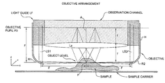
- FIG. 1 shows an objective arrangement in accordance with the present invention.
- FIG. 1 a shows an alternative embodiment of an objective arrangement in accordance with the present invention.
- FIG. 2 a shows an objective arrangement with a line scanner connection.
- FIG. 2 b shows a beam splitter having on its edge opposite circular reflecting partial sections.
- FIG. 3 a shows the cross section of the objective pupil on the beam splitter with the illumination channels BK and the effective area for the viewing FB.
- FIG. 3 b shows an illuminated line L in the object plane, on which focusing is carried out with the objective.
- FIG. 4 a shows an objective arrangement with a connection to a far-field detector.
- FIG. 4 b shows the plane of the objective pupil on the beam splitter with wide field illumination.
- FIG. 4 c shows the scanned light area in the sample plane.
- FIG. 1 shows an objective arrangement that consists of a central lens unit Lz, in which it may be a case of a usual viewing object of a microscope.
- light guides LF are provided in which parallel illumination beams Ls 1 , Ls 2 run in the direction of the sample, at first parallel to the optical axis A of viewing in Lz.
- the illumination beams Ls 1 , Ls 2 arrive at the reflectors R 1 , R 2 , mounted on housing H, which can be imaging mirrors with small aperture, and focus the illumination beams in a direction perpendicular to the optical viewing axis in a point P of the optical axis of the objective Lz.
- R 1 , R 2 can also be flat reflecting mirrors and then display elements with small aperture can be provided in the light guides LF, whereby R 1 , R 2 are used only for deflection in the direction of the sample and the focus in the sample will be generated by the imaging elements.
- the waist of the illumination runs almost parallel in the area of the sample and generates, in the sample, a thin illumination line that is imaged in objective pupil P 3 .
- Objective pupil P 3 , objective Lz and the sample focus P are located here in a 2f arrangement, i.e. in each case at a distance from each other that equals the simple focal length f, so that the distance between the objective pupil P 3 and the sample focus P is 2f (represented in FIG. 1 as “F”).
- the objective can be used for telecentric scanning, for example of an illumination line in the sample.
- a light source LQ is mounted below a beam splitter T that creates two parallel partial beams Ls 1 , Ls 2 that are reflected over a beam splitter MDB and are transferred over a scanner P 2 for movement of the illumination beams over the sample in one direction, scanning optics SO and a tube lens TL for transfer of an intermediate image ZB onto the objective pupil P 2 .
- the beam splitter MDB lies in the conjugate plane of the objective pupil, this beam splitter having on its edge opposite circular reflecting partial sections ( FIG. 2 b ).
- the attachment of the objective according to the lens takes place over the pupil P 3 to the beam of a line scanner, which has an appropriately designed beam splitter, as already described in DE10257237 A 21 , and the transmitting or reflecting surfaces of which can be used.
- the illumination line described here is moved through the sample by way of the scanner P 2 (in the pupil P 3 ) of the line scanner.
- the viewing beam is dotted, the illumination beam is a solid line.
- the image of the sample in the intermediate image ZB is descanned by way of a tube lens, scanning optics and scanner and is imaged onto a slot shutter SB (optional here) in front of a line detector DE, through the surface of the beam splitter MDB necessary for the sample irradiation (except for the circular reflecting points) by means of pinhole optics PO.
- FIG. 3 a shows the cross section of the objective pupil on the MDB with the illumination channels BK and the effective area FB for the viewing.
- FIG. 3 b shows the illuminated line L in the object plane, on which focusing is carried out with the objective and by means of which the detection is recorded.
- the thickness of the line is adjusted, in that the effective numerical aperture of the lateral optics that is focused with variation along the beam direction in the sample. If this NA is decreased, the line width increases accordingly.
- the manipulation of the numerical aperture can also be e.g. by a variable ring shutter in the pupil that is not shown, arranged around the illumination channel. By moving the scanner P 2 perpendicular to the longitudinal direction (x axis), the line is moved perpendicular in y direction on the sample.
- FIG. 4 a shows the arrangement for wide field illumination.
- a splitter can be used for illumination of the sample from two irradiation directions.
- FIG. 4 b shows the plane of the objective pupil on the beam splitter MDB with wide field illumination.
- This advantageously has two line-shaped transmitting areas B 1 , B 2 that are opposite each other on the outer edge, each of which transfers a line-shaped area of the illumination (dotted line) in the direction of the outer area of the objective.
- These areas are imaged with the reflectors in the direction of the sample with small aperture and form a quasi-parallel surface light area of small thickness through the sample.
- the adjustment of the thickness is carried out, in turn, by a shutter in the pupil, which is not shown, that contracts the pupil of the illumination channel along the x axis at the location of the pupil.
- the objective according to the invention is advantageously connected by way of a pupil P 3 as in FIG. 2 a to the beam of a line scanner.
- the illumination is focused in the y direction by a cylinder lens.
- a splitter T e.g. double-refractive medium
- a splitter T can be located in the illumination beam to generate 2 partial beams.
- FIG. 4 c shows the scanned light area in the sample plane (focal plane of the objective).
- the sample light goes over the beam splitter MDB (reflecting) in the direction of an area detector DE.
- a Powell aspherical can optionally be used in front of the cylinder optics ZL 1 in FIG. 4 a for homogenizing the illumination along the y-axis.
- the invention described represents an important expansion of the application possibilities of fast confocal laser scanning microscopes.
- the importance of such a further development can be understood from reading the standard cell biology literature and the fast cellular and subcellular processes described there and the testing methods used there with a large number of dyes.
- the invention has especially great importance for the following processes and procedures:
- the invention described is suitable, among other things, for the examination of development processes, which are mainly characterized by dynamic process in the range of tenths of a second to hours.
- Example applications on the level of symplasts and complete organisms are described here as an example:
Abstract
Description
- B. Alberts et al. (2002): Molecular Biology of the Cell; Garland Science.
- G. Karp (2002): Cell and Molecular Biology: Concepts and Experiments; Wiley Text Books.
- R. Yuste et al. (2000): Imaging neurons—a laboratory Manual; Cold Spring Harbor Laboratory Press, New York.
- R. P. Haugland (2003): Handbook of fluorescent Probes and research Products, 10th Edition; Molecular Probes Inc. and Molecular Probes Europe BV.
-
- Abdul-Karim, M. A. et al. describe, in 2003 in Microvasc. Res., 66:113-125, a long-term analysis of blood vessel changes in the living animal, wherein fluorescence images were recorded at intervals over several days. The 3D data records were evaluated with adaptive algorithms in order to schematically represent movement trajectories.
- Soll, D. R. et al. describe, in 2003 in Scientific World Journ. 3:827-841, a software-based movement analysis of microscopic data of nuclei and pseudopods of living cells in all 3 spatial dimensions.
- Grossmann, R. et al. describe, in 2002 in Glia, 37:229-240 a 3D analysis of the movements of rat microglial cells, whereby the data were recorded over up to 10 hours. At the same time, there were also fast reactions of the glia after traumatic, so that a high data rate and corresponding data volume occurred.
-
- Analysis of living cells in 3D environment with labels, that will be selectively bleached by laser light in 3D, e.g. FRET experiments;
- Analysis of living cells in 3D environment with labels, that will be selectively bleached by laser light in 3D and simultaneously will also be observed outside the ROI, e.g. FRAP AND FLIP experiments;
- Selective analysis of living cells in 3D environment with labels and pharmaceuticals that exhibit manipulation-related changes due to laser illumination, e.g. activation of transmitters in 3D;
- Selective analysis of living cells in 3D environment with labels that exhibit manipulation-related color changes due to laser illumination, e.g. paGFP, Kaede;
- Selective analysis of living cells in 3D environment with very weak labels that e.g. require an optimum balance of confocality and detection sensitivity.
- Living cells in a 3D tissue structure with varying multiple labels, e.g. CFP, GFP, YFP, DsRed, HcRed, etc.
- Living cells in a 3D tissue structure with labels, that have color changes depending on function, e.g. Ca+-Marker
- Living cells in a 3D tissue structure with labels, that have color changes due to development, e.g. transgenic animals with GFP
- Living cells in a 3D tissue structure with labels, that have manipulation-related color changes due to laser illumination, e.g. paGFP, Kaede
- Living cells in a 3D tissue structure with very weak labels that require a restriction of the confocality in favor of the detection sensitivity.
- The latter-named point in combination with the preceding.
Claims (12)
Priority Applications (1)
Application Number | Priority Date | Filing Date | Title |
---|---|---|---|
US11/808,569 US7796328B2 (en) | 2004-07-16 | 2007-06-11 | Laser scanning microscope with illumination perpendicular to the optical axis |
Applications Claiming Priority (5)
Application Number | Priority Date | Filing Date | Title |
---|---|---|---|
DE102004034957 | 2004-07-16 | ||
DE102004034957A DE102004034957A1 (en) | 2004-07-16 | 2004-07-16 | Arrangement for microscopic observation and / or detection and use |
DE102004034957.6 | 2004-07-16 | ||
US10/967,322 US20060012866A1 (en) | 2004-07-16 | 2004-10-19 | Arrangement for microscopic observation and/or detection and use |
US11/808,569 US7796328B2 (en) | 2004-07-16 | 2007-06-11 | Laser scanning microscope with illumination perpendicular to the optical axis |
Related Parent Applications (1)
Application Number | Title | Priority Date | Filing Date |
---|---|---|---|
US10/967,322 Continuation US20060012866A1 (en) | 2004-07-16 | 2004-10-19 | Arrangement for microscopic observation and/or detection and use |
Publications (2)
Publication Number | Publication Date |
---|---|
US20080068710A1 US20080068710A1 (en) | 2008-03-20 |
US7796328B2 true US7796328B2 (en) | 2010-09-14 |
Family
ID=34673263
Family Applications (2)
Application Number | Title | Priority Date | Filing Date |
---|---|---|---|
US10/967,322 Abandoned US20060012866A1 (en) | 2004-07-16 | 2004-10-19 | Arrangement for microscopic observation and/or detection and use |
US11/808,569 Expired - Fee Related US7796328B2 (en) | 2004-07-16 | 2007-06-11 | Laser scanning microscope with illumination perpendicular to the optical axis |
Family Applications Before (1)
Application Number | Title | Priority Date | Filing Date |
---|---|---|---|
US10/967,322 Abandoned US20060012866A1 (en) | 2004-07-16 | 2004-10-19 | Arrangement for microscopic observation and/or detection and use |
Country Status (6)
Country | Link |
---|---|
US (2) | US20060012866A1 (en) |
EP (1) | EP1617255B1 (en) |
JP (1) | JP4970748B2 (en) |
AT (1) | ATE422065T1 (en) |
DE (2) | DE102004034957A1 (en) |
GB (1) | GB2416403A (en) |
Cited By (6)
Publication number | Priority date | Publication date | Assignee | Title |
---|---|---|---|---|
US20150205087A1 (en) * | 2012-08-16 | 2015-07-23 | Leica Microsystems Cms Gmbh | Optical arrangement and a microscope |
US9104020B2 (en) | 2011-10-28 | 2015-08-11 | Leica Microsystems Cms Gmbh | Method and system for illuminating a sample |
US10668468B2 (en) | 2013-08-28 | 2020-06-02 | National University Of Singapore | Micro-textured surface with integrated micro-mirrors for 3D multi-scale microscopy |
US11366299B2 (en) | 2015-10-09 | 2022-06-21 | Leica Microsystems Cms Gmbh | Method and lighting arrangement for illuminating a sample layer with a light sheet |
US11768194B2 (en) | 2018-11-30 | 2023-09-26 | Corning Incorporated | System and method for imaging and illumination for cell confluence measurement |
US11921102B2 (en) | 2019-11-21 | 2024-03-05 | Corning Incorporated | Compact optical imaging system for cell culture monitoring |
Families Citing this family (22)
Publication number | Priority date | Publication date | Assignee | Title |
---|---|---|---|---|
DE102004034983A1 (en) * | 2004-07-16 | 2006-02-02 | Carl Zeiss Jena Gmbh | Light scanning microscope |
DE102007015063B4 (en) * | 2007-03-29 | 2019-10-17 | Carl Zeiss Microscopy Gmbh | Optical arrangement for generating a light sheet |
WO2008131368A2 (en) * | 2007-04-20 | 2008-10-30 | Acucela Inc. | Styrenyl derivative compounds for treating ophthalmic diseases and disorders |
DE102007063274B8 (en) * | 2007-12-20 | 2022-12-15 | Albert-Ludwigs-Universität Freiburg | microscope |
DE102008009216A1 (en) * | 2008-02-13 | 2009-08-20 | Carl Zeiss Microimaging Gmbh | Apparatus and method for spatially high resolution imaging of a structure of a sample |
US8610085B2 (en) * | 2009-08-20 | 2013-12-17 | Bio-Rad Laboratories, Inc. | High-speed cellular cross sectional imaging |
DE102010039950B4 (en) * | 2010-08-30 | 2021-07-22 | Leica Microsystems Cms Gmbh | Microscope with micro and macro objectives |
DE202011110077U1 (en) | 2011-10-28 | 2012-11-29 | Leica Microsystems Cms Gmbh | Arrangement for illuminating a sample |
DE102012211780B4 (en) | 2012-07-05 | 2023-12-07 | Carl Zeiss Microscopy Gmbh | Device for holding and illuminating samples for a microscope |
DE102012211943A1 (en) * | 2012-07-09 | 2014-06-12 | Carl Zeiss Microscopy Gmbh | microscope |
DE102013213781A1 (en) * | 2013-03-20 | 2014-09-25 | Leica Microsystems Cms Gmbh | Method and optical arrangement for manipulating and imaging a microscopic sample |
DE102013211426A1 (en) | 2013-06-18 | 2014-12-18 | Leica Microsystems Cms Gmbh | Method and optical device for microscopically examining a plurality of samples |
JP2015203708A (en) * | 2014-04-10 | 2015-11-16 | オリンパス株式会社 | Microscope device |
DE102015114756B4 (en) | 2014-09-25 | 2021-07-22 | Leica Microsystems Cms Gmbh | Mirror device |
FR3031196B1 (en) | 2014-12-29 | 2017-01-13 | Karla Balaa | DEVICE FOR REALIZING THE LIGHT-SHEET MICROSCOPY |
DE202015009495U1 (en) * | 2015-03-27 | 2017-12-18 | J & M Analytik Ag | Device for illuminating a sample |
LU92695B1 (en) | 2015-04-17 | 2016-10-18 | Leica Microsystems | METHOD AND DEVICE FOR SPIM EXAMINATION OF A SAMPLE |
JP6768289B2 (en) | 2015-12-01 | 2020-10-14 | キヤノン株式会社 | Scanning electron microscope |
DE102016108384B3 (en) | 2016-05-04 | 2017-11-09 | Leica Microsystems Cms Gmbh | Device and method for light sheet-like illumination of a sample |
WO2017207807A1 (en) | 2016-06-03 | 2017-12-07 | Leica Microsystems Cms Gmbh | Light sheet microscope and microscopic method using a light sheet microscope |
DE102017119169B4 (en) | 2016-08-22 | 2023-07-27 | Leica Microsystems Cms Gmbh | Method and device for SPIM analysis of a sample |
EP3832369A1 (en) * | 2019-12-05 | 2021-06-09 | Leica Microsystems CMS GmbH | Light sheet fluorescence microscope |
Citations (36)
Publication number | Priority date | Publication date | Assignee | Title |
---|---|---|---|---|
US1935444A (en) * | 1930-12-19 | 1933-11-14 | Ernst Leitz Optische Werke | Microscope |
US1943510A (en) | 1931-10-15 | 1934-01-16 | Zeiss Carl Fa | Device for light-field and darkfield illumination of microscopic objects |
US1996920A (en) * | 1932-09-14 | 1935-04-09 | Zeiss Carl Fa | Revolving nose-piece for microscopes |
US2097762A (en) * | 1933-05-26 | 1937-11-02 | Ernst Leitz | Microscope |
US2357378A (en) | 1941-12-01 | 1944-09-05 | Bausch & Lomb | Microscope illuminator |
US2809554A (en) * | 1954-07-16 | 1957-10-15 | Zeiss Carl | Microscope objective with low magnification for epi-microscopes |
US3857626A (en) | 1971-12-10 | 1974-12-31 | Bausch & Lomb | Microscope coaxial illumination apparatus |
US3930713A (en) * | 1973-06-22 | 1976-01-06 | Ernst Leitz G.M.B.H. | Incident light illumination instrument for selective light and dark field illumination |
US4127318A (en) | 1975-09-20 | 1978-11-28 | Ernst Leitz Wetzlar Gmbh | Direct illumination apparatus for light and dark field illumination |
US4160578A (en) * | 1978-04-17 | 1979-07-10 | American Optical Corporation | Annular reflector for microscope objective |
EP0019309A1 (en) | 1979-04-11 | 1980-11-26 | Jean Louis Jeanne Chandesais | Ring lighting for the dark ground observation of a precious stone |
US4317613A (en) | 1979-08-27 | 1982-03-02 | Johannes Grosser | Illumination arrangement for microscopes |
US4475796A (en) | 1981-03-13 | 1984-10-09 | Olympus Optical Co., Ltd. | Epidark illumination system |
DE3409657A1 (en) | 1984-03-16 | 1985-09-19 | Fa. Carl Zeiss, 7920 Heidenheim | Dark-field illumination system for microscopes |
US4585315A (en) | 1984-11-13 | 1986-04-29 | International Business Machines Corporation | Brightfield/darkfield microscope illuminator |
US4626079A (en) | 1984-04-13 | 1986-12-02 | Nippon Kogaku K.K. | Dark field illumination apparatus for epi-illumination system |
US4737022A (en) | 1985-07-31 | 1988-04-12 | Carl-Zeiss-Stiftung | Automatic focusing device for reflected light microscopes |
WO1989006817A1 (en) | 1988-01-25 | 1989-07-27 | Czirbik Sandor | Universal condenser for the illumination of objects |
US4881802A (en) | 1987-05-05 | 1989-11-21 | Ernst Leitz Wetzlar Gmbh | Combined bright field-dark field incident light illumination apparatus |
US4964707A (en) | 1988-12-05 | 1990-10-23 | Olympus Optical Co., Ltd. | Differential interference microscope |
JPH03142301A (en) | 1989-10-30 | 1991-06-18 | Erionikusu:Kk | Scanning tunnel microscope |
EP0504940A2 (en) | 1991-03-22 | 1992-09-23 | Olympus Optical Co., Ltd | Microscope illuminating apparatus |
EP0541808A1 (en) | 1990-07-31 | 1993-05-19 | Scalar Corporation | Imaging instrument for observing magnified object |
US5268749A (en) * | 1991-07-26 | 1993-12-07 | Kollmorgen Corporation | Apparatus and method for providing uniform illumination of a sample plane |
US5351169A (en) * | 1992-04-23 | 1994-09-27 | Mitsubishi Kasei Corporation | Lighting device |
US5580162A (en) * | 1994-09-30 | 1996-12-03 | Mitsubishi Chemical Corporation | Lighting device for an observation/image pickup apparatus |
DE19630322A1 (en) | 1995-07-28 | 1997-01-30 | Lab Molecular Biophotonics | Dark field stimulated fluorescence microscope - has given surface of sample stimulated by zonal light beam with detection of resulting fluorescence via optical objective system |
US5859727A (en) * | 1996-07-29 | 1999-01-12 | Olympus Optical Co., Ltd. | Objective unit |
US5926311A (en) | 1997-02-28 | 1999-07-20 | International Business Machines Corporation | Illumination/viewing system for features in transparent materials |
US6064518A (en) * | 1996-08-08 | 2000-05-16 | Carl Zeiss Jena Gmbh | Beam deflecting unit for multiple-axis examination in a microscope |
US6179439B1 (en) | 1998-06-10 | 2001-01-30 | Optical Gaging Products, Inc. | High-incidence programmable surface illuminator for video inspection systems |
US6259557B1 (en) | 1998-04-30 | 2001-07-10 | Nikon Corporation | Device and method for dark field illumination |
US6392793B1 (en) | 1996-07-22 | 2002-05-21 | Kla-Tencor Corporation | High NA imaging system |
US20030076587A1 (en) | 1998-07-30 | 2003-04-24 | Carl Zeiss Jena Gmbh | Confocal theta microscope |
DE10257237A1 (en) | 2001-12-10 | 2003-06-18 | Zeiss Carl Jena Gmbh | Optical system for microscopy comprises focussing the illuminating light on the sample at the plane between it and the eye pupil, with separation of the emitted detection light on or near the same plane |
US6633375B1 (en) * | 1999-01-29 | 2003-10-14 | Leica Microsystems Semiconductor Gmbh | Method and device for optically examining structured surfaces of objects |
Family Cites Families (7)
Publication number | Priority date | Publication date | Assignee | Title |
---|---|---|---|---|
GB415342A (en) * | 1934-03-03 | 1934-08-23 | Carl Reichert | Improvements in illuminating devices for microscopes |
JPS5324637U (en) * | 1976-08-09 | 1978-03-02 | ||
JPS5979817U (en) * | 1982-11-18 | 1984-05-30 | 株式会社ニコン | Objective lens for epidark |
US4974094A (en) * | 1989-12-04 | 1990-11-27 | Yuhkoh Morito | Direct lighting/illuminating system for miniature CCD camera |
JP3217097B2 (en) * | 1991-12-18 | 2001-10-09 | 科学技術振興事業団 | High resolution microscope |
JP3359071B2 (en) * | 1992-12-11 | 2002-12-24 | オリンパス光学工業株式会社 | Epidark objective lens |
JP3634985B2 (en) * | 1999-08-26 | 2005-03-30 | 住友大阪セメント株式会社 | Optical surface inspection mechanism and optical surface inspection apparatus |
-
2004
- 2004-07-16 DE DE102004034957A patent/DE102004034957A1/en not_active Withdrawn
- 2004-10-01 EP EP04023499A patent/EP1617255B1/en not_active Not-in-force
- 2004-10-01 AT AT04023499T patent/ATE422065T1/en not_active IP Right Cessation
- 2004-10-01 DE DE502004008944T patent/DE502004008944D1/en active Active
- 2004-10-19 US US10/967,322 patent/US20060012866A1/en not_active Abandoned
-
2005
- 2005-05-03 GB GB0508927A patent/GB2416403A/en not_active Withdrawn
- 2005-06-30 JP JP2005191511A patent/JP4970748B2/en active Active
-
2007
- 2007-06-11 US US11/808,569 patent/US7796328B2/en not_active Expired - Fee Related
Patent Citations (37)
Publication number | Priority date | Publication date | Assignee | Title |
---|---|---|---|---|
US1935444A (en) * | 1930-12-19 | 1933-11-14 | Ernst Leitz Optische Werke | Microscope |
US1943510A (en) | 1931-10-15 | 1934-01-16 | Zeiss Carl Fa | Device for light-field and darkfield illumination of microscopic objects |
US1996920A (en) * | 1932-09-14 | 1935-04-09 | Zeiss Carl Fa | Revolving nose-piece for microscopes |
US2097762A (en) * | 1933-05-26 | 1937-11-02 | Ernst Leitz | Microscope |
US2357378A (en) | 1941-12-01 | 1944-09-05 | Bausch & Lomb | Microscope illuminator |
US2809554A (en) * | 1954-07-16 | 1957-10-15 | Zeiss Carl | Microscope objective with low magnification for epi-microscopes |
US3857626A (en) | 1971-12-10 | 1974-12-31 | Bausch & Lomb | Microscope coaxial illumination apparatus |
US3930713A (en) * | 1973-06-22 | 1976-01-06 | Ernst Leitz G.M.B.H. | Incident light illumination instrument for selective light and dark field illumination |
US4127318A (en) | 1975-09-20 | 1978-11-28 | Ernst Leitz Wetzlar Gmbh | Direct illumination apparatus for light and dark field illumination |
US4160578A (en) * | 1978-04-17 | 1979-07-10 | American Optical Corporation | Annular reflector for microscope objective |
EP0019309A1 (en) | 1979-04-11 | 1980-11-26 | Jean Louis Jeanne Chandesais | Ring lighting for the dark ground observation of a precious stone |
US4317613A (en) | 1979-08-27 | 1982-03-02 | Johannes Grosser | Illumination arrangement for microscopes |
US4475796A (en) | 1981-03-13 | 1984-10-09 | Olympus Optical Co., Ltd. | Epidark illumination system |
DE3409657A1 (en) | 1984-03-16 | 1985-09-19 | Fa. Carl Zeiss, 7920 Heidenheim | Dark-field illumination system for microscopes |
US4626079A (en) | 1984-04-13 | 1986-12-02 | Nippon Kogaku K.K. | Dark field illumination apparatus for epi-illumination system |
US4585315A (en) | 1984-11-13 | 1986-04-29 | International Business Machines Corporation | Brightfield/darkfield microscope illuminator |
US4737022A (en) | 1985-07-31 | 1988-04-12 | Carl-Zeiss-Stiftung | Automatic focusing device for reflected light microscopes |
US4881802A (en) | 1987-05-05 | 1989-11-21 | Ernst Leitz Wetzlar Gmbh | Combined bright field-dark field incident light illumination apparatus |
WO1989006817A1 (en) | 1988-01-25 | 1989-07-27 | Czirbik Sandor | Universal condenser for the illumination of objects |
US4964707A (en) | 1988-12-05 | 1990-10-23 | Olympus Optical Co., Ltd. | Differential interference microscope |
JPH03142301A (en) | 1989-10-30 | 1991-06-18 | Erionikusu:Kk | Scanning tunnel microscope |
EP0541808A1 (en) | 1990-07-31 | 1993-05-19 | Scalar Corporation | Imaging instrument for observing magnified object |
EP0504940A2 (en) | 1991-03-22 | 1992-09-23 | Olympus Optical Co., Ltd | Microscope illuminating apparatus |
US5325231A (en) * | 1991-03-22 | 1994-06-28 | Olympus Optical Co., Ltd. | Microscope illuminating apparatus |
US5268749A (en) * | 1991-07-26 | 1993-12-07 | Kollmorgen Corporation | Apparatus and method for providing uniform illumination of a sample plane |
US5351169A (en) * | 1992-04-23 | 1994-09-27 | Mitsubishi Kasei Corporation | Lighting device |
US5580162A (en) * | 1994-09-30 | 1996-12-03 | Mitsubishi Chemical Corporation | Lighting device for an observation/image pickup apparatus |
DE19630322A1 (en) | 1995-07-28 | 1997-01-30 | Lab Molecular Biophotonics | Dark field stimulated fluorescence microscope - has given surface of sample stimulated by zonal light beam with detection of resulting fluorescence via optical objective system |
US6392793B1 (en) | 1996-07-22 | 2002-05-21 | Kla-Tencor Corporation | High NA imaging system |
US5859727A (en) * | 1996-07-29 | 1999-01-12 | Olympus Optical Co., Ltd. | Objective unit |
US6064518A (en) * | 1996-08-08 | 2000-05-16 | Carl Zeiss Jena Gmbh | Beam deflecting unit for multiple-axis examination in a microscope |
US5926311A (en) | 1997-02-28 | 1999-07-20 | International Business Machines Corporation | Illumination/viewing system for features in transparent materials |
US6259557B1 (en) | 1998-04-30 | 2001-07-10 | Nikon Corporation | Device and method for dark field illumination |
US6179439B1 (en) | 1998-06-10 | 2001-01-30 | Optical Gaging Products, Inc. | High-incidence programmable surface illuminator for video inspection systems |
US20030076587A1 (en) | 1998-07-30 | 2003-04-24 | Carl Zeiss Jena Gmbh | Confocal theta microscope |
US6633375B1 (en) * | 1999-01-29 | 2003-10-14 | Leica Microsystems Semiconductor Gmbh | Method and device for optically examining structured surfaces of objects |
DE10257237A1 (en) | 2001-12-10 | 2003-06-18 | Zeiss Carl Jena Gmbh | Optical system for microscopy comprises focussing the illuminating light on the sample at the plane between it and the eye pupil, with separation of the emitted detection light on or near the same plane |
Non-Patent Citations (8)
Title |
---|
Haar F.-M. et al: "Developments and Applications of Confocal Theta Microscopy," SPIE Conference on Three-Dimensional and Multidimensional Microscopy, vol. 3605, Jan. 1999. |
Huisken et al., "Optical Sectioning Deep Inside Live Embryos by Selective Plane Illumination Microscope," Science Aug. 13, 2004: 1007-1009. |
Lindek S. et al: "Single-lens theta microscopy: resolution, efficiency and working distance," Journal of Modern Optics, vol. 46, Nr. 5, 1999. |
Lindek S. et al: "Single-lens theta microscopy-new implementation of confocal theta microscopy," Journal of Microscopy, vol. 188, Nr. 3, Dec. 1997. |
M-A Abdul-Karim et al., "Automated tracing and change analysis of angiogenic vasculature from in vivo multiphoton confocal image time series," Microvascular Research 66: 113-125 (2003). |
R. Grossman et al., "Juxtavascular Microglia Migrate Along Brain Microvessels Following Activation During Early Postnatal Development," GLIA 37: 229-240 (2002). |
Stelzer et al., High & isotropic resolution with large samples in the selective plane illumination microscope (SPIM), Abstract, Cell Biology and Cell Biophysics Programme, 2004. |
Swoger J. et al: "A confocal fiber-coupled single-lens theta microscope," Review of Scientific Instruments, vol. 69, Nr. 8, Aug. 1998. |
Cited By (7)
Publication number | Priority date | Publication date | Assignee | Title |
---|---|---|---|---|
US9104020B2 (en) | 2011-10-28 | 2015-08-11 | Leica Microsystems Cms Gmbh | Method and system for illuminating a sample |
US20150205087A1 (en) * | 2012-08-16 | 2015-07-23 | Leica Microsystems Cms Gmbh | Optical arrangement and a microscope |
US9709788B2 (en) * | 2012-08-16 | 2017-07-18 | Leica Microsystems Cms Gmbh | Optical arrangement and a microscope |
US10668468B2 (en) | 2013-08-28 | 2020-06-02 | National University Of Singapore | Micro-textured surface with integrated micro-mirrors for 3D multi-scale microscopy |
US11366299B2 (en) | 2015-10-09 | 2022-06-21 | Leica Microsystems Cms Gmbh | Method and lighting arrangement for illuminating a sample layer with a light sheet |
US11768194B2 (en) | 2018-11-30 | 2023-09-26 | Corning Incorporated | System and method for imaging and illumination for cell confluence measurement |
US11921102B2 (en) | 2019-11-21 | 2024-03-05 | Corning Incorporated | Compact optical imaging system for cell culture monitoring |
Also Published As
Publication number | Publication date |
---|---|
GB0508927D0 (en) | 2005-06-08 |
DE102004034957A1 (en) | 2006-02-02 |
ATE422065T1 (en) | 2009-02-15 |
GB2416403A (en) | 2006-01-25 |
US20060012866A1 (en) | 2006-01-19 |
JP2006030992A (en) | 2006-02-02 |
EP1617255B1 (en) | 2009-01-28 |
DE502004008944D1 (en) | 2009-03-19 |
US20080068710A1 (en) | 2008-03-20 |
JP4970748B2 (en) | 2012-07-11 |
EP1617255A1 (en) | 2006-01-18 |
Similar Documents
Publication | Publication Date | Title |
---|---|---|
US7796328B2 (en) | Laser scanning microscope with illumination perpendicular to the optical axis | |
US20080030850A1 (en) | Arrangement for microscopic observation and/or detection in a light scanning microscope with line scanning and use | |
US5719391A (en) | Fluorescence imaging system employing a macro scanning objective | |
US10901194B2 (en) | Large field of view, high resolution microscope | |
US7468834B2 (en) | Microscope with heightened resolution and linear scanning | |
US20070002435A1 (en) | Double-clad fiber scanning microscope | |
US20120113506A1 (en) | Novel Multi-Point Scan Architecture | |
USRE43702E1 (en) | Microscope with heightened resolution and linear scanning | |
JP2006031007A (en) | Zoom optical system for optical scanning microscope | |
GB2416453A (en) | Zoom optics for a confocal laser scanning microscope | |
CN109211855A (en) | Multiple beam multi-photon microscopic imaging device | |
GB2416260A (en) | Confocal laser scanning microscope with additional widefield illumination | |
JP2006030987A (en) | Optical scanning microscope and its use | |
JP3678456B2 (en) | Scanning laser microscope equipment | |
GB2416261A (en) | Laser scanning microscope with parallel illumination and simultaneous, locally resolved detection | |
JP2006053542A (en) | Line scanning system optical scanning microscope and usage of the same | |
JP2006030997A (en) | Optical scanning microscope with movable perforated disk, and use thereof | |
US20060012870A1 (en) | Light scanning microscope with line-by-line scanning and use | |
GB2416259A (en) | Laser confocal scanning microscope with additional widefield illumination | |
GB2416440A (en) | Laser scanning microscope with parallel illumination via distributed point like light sources | |
CN114577762A (en) | Digital confocal imaging system and method based on digital micro-reflector |
Legal Events
Date | Code | Title | Description |
---|---|---|---|
AS | Assignment |
Owner name: CARL ZEISS MICROIMAGING GMBH, GERMANY Free format text: ASSIGNMENT OF ASSIGNORS INTEREST;ASSIGNOR:CARL ZIESS JENA GMBH;REEL/FRAME:022303/0949 Effective date: 20090209 |
|
FEPP | Fee payment procedure |
Free format text: PAYOR NUMBER ASSIGNED (ORIGINAL EVENT CODE: ASPN); ENTITY STATUS OF PATENT OWNER: LARGE ENTITY |
|
STCF | Information on status: patent grant |
Free format text: PATENTED CASE |
|
CC | Certificate of correction | ||
AS | Assignment |
Owner name: CARL ZEISS MICROSCOPY GMBH, GERMANY Free format text: CHANGE OF NAME;ASSIGNOR:CARL ZEISS MICROIMAGING GMBH;REEL/FRAME:030592/0776 Effective date: 20120403 |
|
FPAY | Fee payment |
Year of fee payment: 4 |
|
MAFP | Maintenance fee payment |
Free format text: PAYMENT OF MAINTENANCE FEE, 8TH YEAR, LARGE ENTITY (ORIGINAL EVENT CODE: M1552) Year of fee payment: 8 |
|
FEPP | Fee payment procedure |
Free format text: MAINTENANCE FEE REMINDER MAILED (ORIGINAL EVENT CODE: REM.); ENTITY STATUS OF PATENT OWNER: LARGE ENTITY |
|
LAPS | Lapse for failure to pay maintenance fees |
Free format text: PATENT EXPIRED FOR FAILURE TO PAY MAINTENANCE FEES (ORIGINAL EVENT CODE: EXP.); ENTITY STATUS OF PATENT OWNER: LARGE ENTITY |
|
STCH | Information on status: patent discontinuation |
Free format text: PATENT EXPIRED DUE TO NONPAYMENT OF MAINTENANCE FEES UNDER 37 CFR 1.362 |
|
FP | Lapsed due to failure to pay maintenance fee |
Effective date: 20220914 |