US7769415B2 - System and method for activating a communication device based on usage information - Google Patents
System and method for activating a communication device based on usage information Download PDFInfo
- Publication number
- US7769415B2 US7769415B2 US10/995,220 US99522004A US7769415B2 US 7769415 B2 US7769415 B2 US 7769415B2 US 99522004 A US99522004 A US 99522004A US 7769415 B2 US7769415 B2 US 7769415B2
- Authority
- US
- United States
- Prior art keywords
- activation
- cycle
- mode
- mobile communication
- time
- Prior art date
- Legal status (The legal status is an assumption and is not a legal conclusion. Google has not performed a legal analysis and makes no representation as to the accuracy of the status listed.)
- Active, expires
Links
Images


Classifications
-
- H—ELECTRICITY
- H04—ELECTRIC COMMUNICATION TECHNIQUE
- H04W—WIRELESS COMMUNICATION NETWORKS
- H04W52/00—Power management, e.g. TPC [Transmission Power Control], power saving or power classes
- H04W52/02—Power saving arrangements
- H04W52/0209—Power saving arrangements in terminal devices
- H04W52/0251—Power saving arrangements in terminal devices using monitoring of local events, e.g. events related to user activity
- H04W52/0258—Power saving arrangements in terminal devices using monitoring of local events, e.g. events related to user activity controlling an operation mode according to history or models of usage information, e.g. activity schedule or time of day
-
- H—ELECTRICITY
- H04—ELECTRIC COMMUNICATION TECHNIQUE
- H04M—TELEPHONIC COMMUNICATION
- H04M1/00—Substation equipment, e.g. for use by subscribers
- H04M1/72—Mobile telephones; Cordless telephones, i.e. devices for establishing wireless links to base stations without route selection
- H04M1/724—User interfaces specially adapted for cordless or mobile telephones
- H04M1/72448—User interfaces specially adapted for cordless or mobile telephones with means for adapting the functionality of the device according to specific conditions
- H04M1/72451—User interfaces specially adapted for cordless or mobile telephones with means for adapting the functionality of the device according to specific conditions according to schedules, e.g. using calendar applications
-
- H—ELECTRICITY
- H04—ELECTRIC COMMUNICATION TECHNIQUE
- H04W—WIRELESS COMMUNICATION NETWORKS
- H04W52/00—Power management, e.g. TPC [Transmission Power Control], power saving or power classes
- H04W52/04—TPC
- H04W52/18—TPC being performed according to specific parameters
- H04W52/28—TPC being performed according to specific parameters using user profile, e.g. mobile speed, priority or network state, e.g. standby, idle or non transmission
- H04W52/287—TPC being performed according to specific parameters using user profile, e.g. mobile speed, priority or network state, e.g. standby, idle or non transmission when the channel is in stand-by
-
- Y—GENERAL TAGGING OF NEW TECHNOLOGICAL DEVELOPMENTS; GENERAL TAGGING OF CROSS-SECTIONAL TECHNOLOGIES SPANNING OVER SEVERAL SECTIONS OF THE IPC; TECHNICAL SUBJECTS COVERED BY FORMER USPC CROSS-REFERENCE ART COLLECTIONS [XRACs] AND DIGESTS
- Y02—TECHNOLOGIES OR APPLICATIONS FOR MITIGATION OR ADAPTATION AGAINST CLIMATE CHANGE
- Y02D—CLIMATE CHANGE MITIGATION TECHNOLOGIES IN INFORMATION AND COMMUNICATION TECHNOLOGIES [ICT], I.E. INFORMATION AND COMMUNICATION TECHNOLOGIES AIMING AT THE REDUCTION OF THEIR OWN ENERGY USE
- Y02D30/00—Reducing energy consumption in communication networks
- Y02D30/70—Reducing energy consumption in communication networks in wireless communication networks
Definitions
- the present invention relates to a system and method controlling operation of a communication device, more particularly operation of the device using activation data associated with the device.
- a wireless connection to a server allows a mobile communication device to receive updates to previously received information and communications.
- the handheld devices optimally are lightweight, compact, and low power to facilitate usage by professionals on the go.
- the devices can be placed into reduced power or sleep modes, where portions of the device (such as the display and alarms) are either not used, powered off, or used in a restricted, power-saving mode.
- Such modes are generally programmable, wherein the user manually programs the device to have: (i) a start or sleep time; and (ii) an end or wake-up time.
- the devices automatically enter a predetermined sleep mode and shut off predetermined portions of the devices.
- a sleep mode sufficient power is still provided to the devices in order for it to maintain its data, essential programs and clock information and to operate programs and processes during the sleep mode.
- the devices are typically brought back to a full power mode, where all functionality of the devices are available to the user.
- prior art systems and methods for power control of such devices are difficult to program, typically requiring that a user enter a series of on and off times for the device. Further, once a programmed time has been entered, a user may subsequently need to use the device during the sleep mode, thereby requiring him to manually activate the device from its sleep mode, then actively return the device to its sleep mode once he is finished with it. This can happen, for example, when the user has sent an early evening time for entering the sleep mode, but subsequently continually uses the device later in the evening before he goes to bed for the night.
- a handheld mobile communication device comprises: a casing for housing a display and a keyboard; a microprocessor controlling aspects of the keyboard and display; and a power application operating on the microprocessor.
- the application monitors activation cycles of the device, stores activation data related to the activation cycles and identifies a new activation cycle for the device utilizing an activation pattern derived from the activation data.
- the power application may monitor a status at least one of: a sensor, a power switch and an activation event relating to the device to determine an activation boundary for at least one of the activation cycles.
- the new activation cycle may progress through a fully on mode and a mode selected from a partially on mode and a fully off mode during its cycle.
- the new activation cycle may adjust activation boundaries depending on the day of the week tracked by the device.
- the activation cycle may progress through at least three different power modes during its cycle.
- the device may further comprise an accelerometer. Therein the power application would monitor a status of the accelerometer to determine an activation boundary for at least one of the activation cycles.
- the power application may utilize signals from the accelerometer to determine a distance displaced by the device.
- the signals are used to determine when the device has moved from a resting position and when the device is returned to about the resting position.
- a method for controlling a power cycle for a mobile communication device comprises: monitoring activation cycles of the device; storing activation data related to the activation cycles; and identifying a new activation cycle for the device utilizing an activation pattern derived from the activation data.
- monitoring activation cycles may comprise monitoring a status at least one of: a sensor, a power switch and an activation event relating to the device to determine an activation boundary for at least one of the activation cycles.
- the new activation cycle may progress through a fully on mode and a mode selected from a partially on mode and a fully off mode during its cycle.
- the new activation cycle may adjust activation boundaries depending on the day of the week tracked by the device.
- the activation cycle may progress through at least three different power modes during its cycle.
- an accelerometer may be used to monitor the activation cycles of the device.
- signals from the accelerometer may be used to determine a distance displaced by the device.
- the signals may be used to determine when the device is moved from a resting position and when the device is returned to about the resting position.
- FIG. 1 illustrates a block diagram of an exemplary mobile device that incorporates an embodiment of the invention
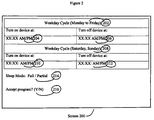
- FIG. 2 illustrates a screen display provided on the device when operating the embodiment of FIG. 1 ;
- FIG. 3 illustrates a flow diagram of programming a new activation cycle process associated with the embodiment of FIG. 1 .
- FIG. 1 illustrates a handheld mobile communication device 10 including a housing, an input device (e.g. keyboard 14 A or thumbwheel 14 B) and an output device (a display 16 ), which is preferably a graphic Liquid Crystal Display (LCD). Other types of output devices may alternatively be utilized.
- a processing device (a microprocessor 18 ) is shown schematically in FIG. 1 as coupled between keyboard 14 A, thumbwheel 14 B, display 16 and a series of other internal devices to device 10 .
- the microprocessor 18 controls the operation of the display 16 , as well as the overall operation of the device 10 , in response to actuation of keys on the keyboard 14 A or thumbwheel 14 B by a user.
- Exemplary microprocessors for microprocessor 18 include Data 950 (trade-mark) series microprocessors and the 6200 series microprocessor, both available from Intel Corporation.
- the keyboard may include a mode selection key, or other hardware or software for switching between text entry and telephony entry.
- a backlighting system is almost invariably used to assist in the viewing display 16 , especially under low-light conditions.
- a typical backlighting system comprises a series of LEDs and a controller to control activation of the LEDs. Depending on a brightness level selected for display 16 , all or some of the LEDs may be powered in a full duty cycle or a duty-cycle approaching 0%.
- FIG. 1 In addition to the microprocessor 18 , other internal devices of the device 10 are shown schematically in FIG. 1 . These devices include: a communication subsystem 100 , a short-range communication subsystem 102 , keyboard 14 A, thumbwheel 14 B and display 16 . Other input/output devices include a set of auxiliary I/O devices 106 , a serial port 108 , a speaker 110 and a microphone 112 . Memory for device 10 is provided in flash memory 116 and Random Access Memory (RAM) 118 . Finally, additional sensor 120 and various other device subsystems (not shown) are provided. The device 10 is preferably a two-way radio frequency (RF) communication device having voice and data communication capabilities. In addition, device 10 preferably has the capability to communicate with other computer systems via the Internet.
- RF radio frequency
- Operating system software executed by the microprocessor 18 is preferably stored in a computer readable medium, such as flash memory 116 , but may be stored in other types of memory devices, such as read only memory (ROM) or similar storage element.
- system software, specific device applications, or parts thereof may be temporarily loaded into a volatile store, such as RAM 118 .
- Communication signals received by the mobile device may also be stored to RAM 118 .
- Microprocessor 18 in addition to its operating system functions, enables execution of software applications on device 10 .
- a set of software applications that control basic device operations such as a voice communication module 130 A and a data communication module 130 B, may be installed on the device 10 during manufacture or downloaded thereafter.
- Cell mapping module 130 C may also be installed on device 10 during manufacture.
- additional software modules illustrated as an other software module 130 N, which may be, for instance, a personal information manager (PIM) application, may be installed during manufacture or downloaded thereafter into device 10 .
- PIM application is preferably capable of organizing and managing data items, such as e-mail messages, calendar events, voice mail messages, appointments, and task items.
- PIM application is also preferably capable of sending and receiving data items via a wireless network 140 .
- data items managed by PIM application are seamlessly integrated, synchronized and updated via wireless network 140 with device user's corresponding data items stored or associated with a host computer system.
- Communication functions are performed through the communication subsystem 100 , and possibly through the short-range communication subsystem 102 .
- Communication subsystem 100 includes receiver 150 , transmitter 152 and one or more antennas, illustrated as receive antenna 154 and transmit antenna 156 .
- communication subsystem 100 also includes processing module, such as digital signal processor (DSP) 158 and local oscillators (LOs) 160 .
- DSP digital signal processor
- LOs local oscillators
- communication subsystem 100 of the device 10 may be designed to operate with the Mobitex (trade-mark), DataTAC (trade-mark) or General Packet Radio Service (GPRS) mobile data communication networks and also designed to operate with any of a variety of voice communication networks, such as Advanced Mobile Phone Service (AMPS), Time Division Multiple Access (TDMA), Code Division Multiple Access CDMA, Personal Communication Service (PCS), Global System for Mobile Communication (GSM), etc.
- AMPS Advanced Mobile Phone Service
- TDMA Time Division Multiple Access
- CDMA Code Division Multiple Access
- PCS Personal Communication Service
- GSM Global System for Mobile Communication
- Other types of data and voice networks, both separate and integrated, may also be utilized with device 10 .
- Network access requirements vary depending upon the type of communication system. For example, in the Mobitex (trade-mark) and DataTAC (trade-mark) networks, mobile devices are registered on the network using a unique Personal Identification Number (PIN) associated with each device. In GPRS networks, however, network access is associated with a subscriber or user of a device. A GPRS device therefore requires a subscriber identity module, commonly referred to as a Subscriber Identity Module (SIM) card, in order to operate on a GPRS network.
- SIM Subscriber Identity Module
- device 10 may send and receive communication signals over communication network 140 .
- Signals received from communication network 140 by the receive antenna 154 are routed to receiver 150 , which provides for signal amplification, frequency down conversion, filtering, channel selection, etc., and may also provide analog to digital conversion. Analog-to-digital conversion of received signals allows the DSP 158 to perform more complex communication functions, such as signal demodulation and decoding.
- signals to be transmitted to network 140 are processed (e.g., modulated and encoded) by DSP 158 and are then provided to transmitter 152 for digital to analog conversion, frequency up conversion, filtering, amplification and transmission to communication network 140 (or networks) via the transmit antenna 156 .
- DSP 158 provides for control of receiver 150 and transmitter 152 .
- gains applied to communication signals in receiver 150 and transmitter 152 may be adaptively controlled through automatic gain control algorithms implemented in DSP 158 .
- a received signal such as a text message or web page download
- the received signal is then further processed by microprocessor 18 for an output to the display 16 , or alternatively to some other auxiliary I/O devices 106 .
- a device user may also compose data items, such as e-mail messages, using keyboard 14 A, thumb-wheel 14 B and/or some other auxiliary I/O device 106 , such as a touchpad, a rocker switch or some other type of input device.
- the composed data items may then be transmitted over communication network 140 via communication subsystem 100 .
- a voice communication mode In a voice communication mode, overall operation of device 10 is substantially similar to the data communication mode, except that received signals are output to speaker 110 , and signals for transmission are generated by microphone 112 .
- Alternative voice or audio I/O subsystems such as a voice message recording subsystem, may also be implemented on device 10 .
- display 16 may also be utilized in voice communication mode, for example, to display the identity of a calling party, the duration of a voice call, or other voice call related information.
- Short-range communication subsystem 102 enables communication between device 10 and other proximate systems or devices, which need not necessarily be similar devices.
- the short-range communication subsystem may include an infrared device and associated circuits and components, or a Bluetooth (trade-mark) communication module to provide for communication with similarly-enabled systems and devices.
- Powering the entire electronics of the mobile handheld communication device is power source 170 .
- the power source 170 includes one or more batteries. More preferably, the power source 170 is a single battery pack, especially a rechargeable battery pack.
- Power switch 172 provides an “on/off” switch for device 10 . Upon activation of power switch 172 a process operating on device 10 is initiated to turn on device 10 . Upon deactivation of power switch 172 , another process is initiated to turn off device 10 . Power to device 10 may also be controlled by other devices and by internal software applications, as described further below.
- the embodiment provides a system and method for programming device 10 to enter a partially on (i.e. sleep) mode wherein device 10 operates in a lower power consumption mode than when all components of device 10 are powered.
- Device 10 can be placed in one of several power consumption modes including: a fully on mode, a partially on mode and a fully off mode.
- the embodiment also provides a learning mode wherein time activation boundaries for the sleep mode can be learned by device 10 by monitoring its usage. This is accomplished by monitoring for activation of device 10 (by monitoring for example, use of the device, powering on of the device or sensing movement of the device) and power application software installed on device 10 . Each is described in turn.
- the power application can detect activation of power switch 172 .
- device 10 has one or more sensors 120 which can be used to detect its state of activation.
- Each sensor 120 is an activation sensor providing an indication of movement or usage of device 10 .
- the activation sensor may be a mercury switch, an accelerometer or any other motion sensing device which can be incorporated within device 10 . If sensor 120 is implemented as a mercury switch (or a comparable tilt switch), then electrical signals generated from the switch are provided to microprocessor 18 and software operating on microprocessor 18 is provided to detect signals from the switch and to determine whether the signals received mean that device 10 is at rest or is moving.
- sensor 120 is implemented as an accelerometer, signals therefrom can be used by the power application to detect motion and to detect a displacement vector, since accelerometers, as force measuring devices, provide force information which can be used to derive displacement information using mathematical integration methods.
- signals from the accelerometer can be used to detect when device 10 is moved from its resting position to an active position and when device 10 is returned to its resting position.
- sensor 120 may be a spring loaded switch which is in one position (either open or closed) when device 10 is placed flatly on a surface (e.g. flat on its back, if sensor 120 is a spring-loaded switch located on the back of device 10 ) and is automatically switched to a second position (either closed or open) when device 10 is lifted from the surface.
- the application can detect when device 10 is docked and undocked in its cradle.
- Other embodiments may use wireless systems, such as Bluetooth-enabled (trade-mark) systems, to detect when device 10 is near a detecting or docking station.
- Other types of sensors known in the art may be used for sensor 120 . For each type of sensor 120 , depending on its sensing dynamics, one detection of one state will indicate that device 10 is being moved and detection of another state will indicate that device 10 has stopped being moved. It will be appreciated that for each of the different types of sensors for motion sensor 120 , an appropriate software interface is provided to enable to the power application to register the status of sensor 120 .
- sensor 120 is a light sensor which is used by power application to detect when it is in a lit, dimly lit or unlit environment or when it is nighttime or daylight environment.
- the power application may also use data from sensor 120 with its data on the current time, date and location of device 10 to determine ambient daylight conditions for device 10 .
- multiple sensors 120 may be provided and the power application may provide different emphasis on signals provided from different sensors 120 .
- the power application it is embodied in a software application (for example, as one of the software applications described above) enabling it to selectively control power of one or more internal elements of device 10 , including, for example, display 16 , keyboard 14 A, thumbwheel 14 B, microphone 112 , short range communication module 102 and communication subsystem 100 .
- the power application operates on microprocessor 18 , has access to the system clock of device 10 and can selectively provide power control signals to one or more of the internal elements.
- Such power control signals include signals: to turn off the element completely; activate the element in a full power, full capability mode; and activate the element in a mode which provides capabilities somewhere between full power and no power.
- the power application operates in several modes.
- a first mode is an initial programming mode where a user enters a time schedule as an activation cycle for device 10 .
- a second mode is a learning mode where actual activation cycles for device 10 are tracked and stored as activation data.
- a third mode analyzes the activation data, identifies one or more patterns for activation cycles from the activation data, and selectively identifies a new activation schedule(s) for device 10 . Each mode is described in turn.
- device 10 has a programming mode allowing its user to enter specific time data relating to an activation cycle for device 10 .
- the user accesses a programming menu in device 10 and accesses a scheduler, then enters data for an activation cycle using keyboard 14 A.
- data can be downloaded to device 10 from a remote source.
- power application generates screen 200 on display 16 which is a daily diary in a graphical format allowing the user to enter activation times and events into the diary.
- Screen 200 provides display text 202 inviting the user to enter “on” and “off” times in weekday fields 204 and 206 as activation boundaries for weekdays.
- text prompts 208 and fields 210 and 212 allow the user to enter “on” and “off” times as activation boundaries for weekend cycles. Text on the screen may also invite the user to select what level of power is to be provided during a sleep mode at field 214 .
- power application processes the time data and updates or generates an activation cycle for device 10 . Thereafter, power application monitors its internal clock to determine the current time and date and automatically turns on and off identified elements in device 10 according to the time data stored for the activation cycle.
- the deployment and implementation of the scheduler may be implemented in any programming language.
- power application allows device 10 to automatically move from one power state to another when a predetermined event occurs. Such an event can be considered to be an “auto-on” or “auto-off” event for device 10 .
- an event can be considered to be an “auto-on” or “auto-off” event for device 10 .
- power application can be set to cause device 10 to move to a full power mode.
- subsystem 102 is enabled and no message is received after a certain set time limit
- power application can be set to cause device 10 to move to a lower power mode and disable power to subsystem 102 .
- Signals and absence of signals from other elements in device 10 can be used by the power application to change the power state of device 10 .
- device 10 provides a similar user interface of menu screen(s) on display 16 to screen 200 .
- power application provides learning of actual times of activation of device 10 by having device 10 detect and track when it is being used and not used.
- the first step is to place device 10 into a learning mode for the activation cycles of the device as it is normally used.
- the second step is to collect time and event data for the activation cycles to determine activation boundaries for a new activation cycle based on the collected data. Each is described in turn.
- device 10 allows the user to initiate the learning mode by making a selection in the programming menu of device 10 .
- the learning mode may always be activated or may be programmed to be activated at a certain time or after detection of a certain event.
- data is collected on usage and non-usage times of device 10 .
- One technique for detecting when device 10 is being used is to infer usage when device 10 is detected as it is being moved. For example, when a user is finished with device 10 for the day, he may rest it on a desk in a resting position. If the user subsequently picks up device 10 , it detects movement from the resting position.
- Another technique is to detect when the device is activated, e.g. when it is turned on using power switch 172 , when a key is depressed, when the thumbwheel is turned or depressed or when it is docked to a docking device.
- power application Upon detection of use of device 10 , power application begins a timer which is used to track time of use after activation. After a predetermined length of time of non usage (e.g. 5, 10, 15, 20, 30, 45, 60 minutes or more), power application can selectively mark device 10 as not being used and can place device 10 in a lower power consumption mode.
- the absence of use may be determined by monitoring the presence or absence of an event.
- the events may include: activation or non-activation of a key on keyboard 14 A or scrolling, depressing or non-activation of thumbwheel 14 B, movement or non-movement of device 10 , active turn off of device 10 , docking or undocking of device 10 from a docking device and return of device 10 to its resting position.
- the detection of use and then the detection of absence of use would complete one activation cycle for device 10 . Power application tracks the time and duration of this activation cycle.
- Power application tracks several activation cycles (as described above) over several intervals.
- the intervals can be any number of hours, days, weeks, months or any other time interval. These intervals can be programmed into the power application.
- the power application analyzes the time and event data stored in the second mode; identifies any time and event pattern(s) from the activation cycles; and utilizes the time and event patterns to identify a new activation cycle.
- An example of an analysis of time data for the third mode is provided where the user of device 10 habitually uses device 10 on around 10:45 PM (+/ ⁇ 15 minutes), uses it for between 5 to 20 minutes, then does not use it again until sometime between 8:00 to 9:00 AM the next morning.
- power application determines at least one optimum time to turn device 10 for the remainder of the day and at least one optimum time to activate device 10 at the start of the next day.
- the time data may be analyzed for patterns to identify when the device was turned on at night, for how long and on what days.
- power application may set a turn off time for the new activation cycle as some time after the latest turn on time at night.
- the time data may be analyzed for patterns in when the device was turned on in the morning and on what days.
- power application may identify a new activation cycle to turn on time as some time before the earliest turn on time.
- Other more aggressive approaches may be used to determine either a turn off or turn on time.
- the patterns may also identify weekend usage patterns, seasonal patterns and holiday patterns.
- the patterns may also identify a staged increase or decrease of usage of device 10 . For example, after a certain time at night, only selected functionalities are disabled, but when the time moves to the middle of the night, then one or more functionalities are also disabled. As the time moves to the early morning, one or more of the functionalities are selectively enabled.
- the first programming mode of operation of device 10 does not necessarily have to be executed in order to perform the second mode.
- the data may be sent to a central server for further analysis and use with other data.
- the activation cycle may be linked to a heating cycle of the home of the user.
- step 306 power application waits for activation of device 10 and then starts a timer.
- activation of the device can be triggered from a signal from sensor 120 , activation of switch 172 , depressing of the keyboard or detection of an “auto-on” event.
- the timer is implemented in software using the internal clock available from microprocessor 18 and data for the timer is stored in memory 116 .
- step 308 the power application waits for detection of deactivation of device 10 and then stops the timer per step 308 .
- deactivation of device 10 can be triggered from another signal from sensor 120 , deactivation of switch 172 , or detection of an “auto-off” event.
- step 310 after deactivation of device 10 is detected, power application calculates a time for the activation cycle just completed from the data associated with the timer and stores additional data relating to the activation cycle, such as the exact start time and date, the end time and date, and the events triggering the beginning and end of the cycle. Steps 306 , 308 and 310 are repeated for a number of predetermined cycles in step 312 to generate a historic set of data.
- step 314 the historic data is analyzed and an adjustment of activation and deactivation times for device 10 is made based on the analysis of the historic data. For example, if the data indicates that for every weekday the device is at rest (process 306 ) at about 10:30 p.m. every night, until 6:30 a.m. the next morning, the power application can use the information to place device 10 in a fully off mode or partially on mode between 10:30 p.m. (or shortly thereafter) until 6:30 a.m. (or shortly therebefore). Such events can be tracked in a data log and counters can be used to track “on” and “off” times.
- Time granularity filters can be applied such that times are recorded in adjustable increments, e.g. every 5, 6, 10, 15, 20 or 30 minutes, thereby reducing the number of different times which are tracked by the power application. Additionally, days can be tracked allowing different power control modes to be implemented during weekdays and weekends. The analysis can also filter out activation and deactivation cycles which do not occur with sufficient frequency to indicate a continually repeated activation pattern. Furthermore, user profiles can also be used as time filters. Exemplary user profiles such as “Vacation Mode”, “Travel Mode” and “Meeting Mode” may be provided which systematically configure an appropriate power cycle for device 10 . For example, each mode may change the on-time and off-time for specific days, weekdays and weekends according to expected usage patterns during a vacation, traveling (e.g. while flying and in a restricted usage area in an airport) and while attending a meeting.
- algorithm 300 may be implemented as a series of interrupt routines, thereby allowing other applications to operate concurrently with it in a real time manner. Other implementations providing real time detection and monitoring of usage may be used.
- the power application can adjust activation of components for power consumption of device 10 , by having it operate in a fully on mode, a fully off mode and a partially on mode.
- the fully off (deep sleep) mode power is provided to only a minimal set of component to enable device 10 to operate.
- These components typically include those which at a minimum, provide power to microprocessor 18 and its related memory, clocks and other devices to allow device 10 to maintain its internal clock, software applications and data, and recognize a stimulus (e.g. activation of the power on button) to revive device 10 from its fully off/deep sleep mode.
- one or more functionalities of device 10 are either disabled or reduced.
- one or both of communication system 100 and communication subsystem 102 may be disabled.
- the backlighting system for display 16 may be reduced in intensity; to conserve power, the backlight system is either set to activate the LEDs at a low duty cycle frequency or not activate the LEDs at all.
- Other internal devices of device 10 can also be programmed to operate in different power modes. It will be appreciated that there may be several partially on modes where different sets of functionalities may be enabled/disabled in each mode.
- power to other internal devices of device 10 may controlled by a power cycle controlled by the embodiment.
- Such other devices can include: a radio transmitter, a radio receiver, blacklighting for the display, a microphone, an LED indicator, a speaker and a vibrator motor. Power provided to any such device can be varied on the sleep level of device 10 .
- the collected data may be provided from device 10 to a remote device, such as a web server.
- a remote device such as a web server.
- the data can be analyzed and used to operate other devices. For example, a user's sleeping pattern identified by the embodiment may be sent to the server. Then, from the server, appropriate software can then remotely downloaded data relating to the pattern to an electronic thermostat associated with the residence of the user. At the thermostat, its programmable temperature cycle(s) can be configured to appropriately reduce its target temperature during the sleep cycles identified in the pattern. Similarly, a programmable alarm system may be able to use the sleep pattern data to configure different alarm conditions and monitoring modes for the residence.
Abstract
Description
Claims (20)
Priority Applications (2)
| Application Number | Priority Date | Filing Date | Title |
|---|---|---|---|
| US10/995,220 US7769415B2 (en) | 2004-11-24 | 2004-11-24 | System and method for activating a communication device based on usage information |
| US12/796,469 US20100291977A1 (en) | 2004-11-24 | 2010-06-08 | System and method for activating a communication device based on usage information |
Applications Claiming Priority (1)
| Application Number | Priority Date | Filing Date | Title |
|---|---|---|---|
| US10/995,220 US7769415B2 (en) | 2004-11-24 | 2004-11-24 | System and method for activating a communication device based on usage information |
Related Child Applications (1)
| Application Number | Title | Priority Date | Filing Date |
|---|---|---|---|
| US12/796,469 Continuation US20100291977A1 (en) | 2004-11-24 | 2010-06-08 | System and method for activating a communication device based on usage information |
Publications (2)
| Publication Number | Publication Date |
|---|---|
| US20060116178A1 US20060116178A1 (en) | 2006-06-01 |
| US7769415B2 true US7769415B2 (en) | 2010-08-03 |
Family
ID=36568013
Family Applications (2)
| Application Number | Title | Priority Date | Filing Date |
|---|---|---|---|
| US10/995,220 Active 2027-05-12 US7769415B2 (en) | 2004-11-24 | 2004-11-24 | System and method for activating a communication device based on usage information |
| US12/796,469 Abandoned US20100291977A1 (en) | 2004-11-24 | 2010-06-08 | System and method for activating a communication device based on usage information |
Family Applications After (1)
| Application Number | Title | Priority Date | Filing Date |
|---|---|---|---|
| US12/796,469 Abandoned US20100291977A1 (en) | 2004-11-24 | 2010-06-08 | System and method for activating a communication device based on usage information |
Country Status (1)
| Country | Link |
|---|---|
| US (2) | US7769415B2 (en) |
Cited By (4)
| Publication number | Priority date | Publication date | Assignee | Title |
|---|---|---|---|---|
| US20100131788A1 (en) * | 2008-11-24 | 2010-05-27 | International Business Machines Corporation | Motion Sensor Assisted Auto-Shutdown Mechanism in Portable Audio Systems |
| US20130157722A1 (en) * | 2011-12-20 | 2013-06-20 | Lg Electronics Inc. | Mobile terminal and controlling method thereof |
| US20160301229A1 (en) * | 2015-04-09 | 2016-10-13 | TwinTech Industry, Inc. | Portable powerbank with integrated promotional-video capabilities and methods of use |
| US20190171587A1 (en) * | 2015-03-23 | 2019-06-06 | International Business Machines Corporation | Communication mode control for wearable devices |
Families Citing this family (33)
| Publication number | Priority date | Publication date | Assignee | Title |
|---|---|---|---|---|
| US7911358B2 (en) * | 2002-10-08 | 2011-03-22 | Johnson Controls Technology Company | System and method for enrollment of a remotely controlled device in a trainable transmitter |
| US20070099679A1 (en) * | 2005-11-01 | 2007-05-03 | Mikko Saarisalo | Wireless near field communication control using device state or orientation |
| US7725093B2 (en) * | 2006-03-29 | 2010-05-25 | Intel Corporation | Method and apparatus for a power-efficient framework to maintain data synchronization of a mobile personal computer to simulate a connected scenario |
| US7729664B2 (en) * | 2006-04-20 | 2010-06-01 | Palm, Inc. | Technique for reducing interference to radio operations on a computing device |
| US8760267B2 (en) * | 2006-08-28 | 2014-06-24 | Gentex Corporation | System and method for enrollment of a remotely controlled device in a trainable transmitter |
| US7548203B2 (en) | 2006-09-15 | 2009-06-16 | Nokia Corporation | Performance and power management in direction of arrival determination by utilizing sensor information |
| US20080168267A1 (en) * | 2007-01-09 | 2008-07-10 | Bolen Charles S | System and method for dynamically configuring a mobile device |
| US20080307237A1 (en) * | 2007-06-08 | 2008-12-11 | Michael Holtzman | Method for improving accuracy of a time estimate used to authenticate an entity to a memory device |
| US20090215439A1 (en) * | 2008-02-27 | 2009-08-27 | Palm, Inc. | Techniques to manage audio settings |
| TWI451801B (en) * | 2008-08-12 | 2014-09-01 | Princeton Technology Corp | Method of lamp brightness adjusting |
| GB0815322D0 (en) * | 2008-08-21 | 2008-09-24 | Symbian Software Ltd | A diagnostic tool |
| DE102008048468A1 (en) * | 2008-09-24 | 2010-04-08 | Siemens Enterprise Communications Gmbh & Co. Kg | Method, telephone, telecommunication system and device for controlling the energy consumption of a telephone |
| JP5287110B2 (en) * | 2008-10-03 | 2013-09-11 | 富士通モバイルコミュニケーションズ株式会社 | Wireless device |
| US20100151878A1 (en) * | 2008-12-15 | 2010-06-17 | Ali Nader | Radio Environment Measurements in a Mobile Communication System |
| DE102008062770B4 (en) * | 2008-12-18 | 2023-04-06 | Gigaset Communications Gmbh | Telecommunications network node and method of operating it |
| CN101765188A (en) * | 2008-12-25 | 2010-06-30 | 英华达(上海)电子有限公司 | Energy-saving method of running gear and running gear adopting the same |
| US9762748B2 (en) | 2009-06-08 | 2017-09-12 | Mitel Networks Corporation | Power management in an internet protocol (IP) telephone |
| US8515340B2 (en) * | 2009-06-08 | 2013-08-20 | Mitel Networks Corporation | Power management in an internet protocol (IP) telephone |
| US8754789B2 (en) * | 2009-11-24 | 2014-06-17 | Mitel Networks Corporation | Power management system and method for mobile applications using location based services |
| US8588869B2 (en) | 2010-01-19 | 2013-11-19 | Hand Held Products, Inc. | Power management scheme for portable data collection devices utilizing location and position sensors |
| GB201010674D0 (en) * | 2010-06-24 | 2010-08-11 | Avin Electronics Ltd | Power control module |
| US20120146535A1 (en) * | 2010-12-09 | 2012-06-14 | Goyatek Technology Inc. | Led controller asic and pwm module thereof |
| FR2976360B1 (en) * | 2011-06-08 | 2014-01-03 | Smart Impulse | METHOD FOR ANALYZING THE ELECTRICITY CONSUMPTION OF A SITE EQUIPPED WITH A PLURALITY OF ELECTRICAL EQUIPMENTS |
| US9621371B2 (en) * | 2012-07-24 | 2017-04-11 | Honeywell International Inc. | Wireless sensor device with wireless remote programming |
| US9575823B2 (en) * | 2013-04-29 | 2017-02-21 | Hewlett Packard Enterprise Development Lp | Recording unstructured events in context |
| US10170019B2 (en) * | 2014-01-07 | 2019-01-01 | Illinois Tool Works Inc. | Feedback from a welding torch of a welding system |
| JP6510231B2 (en) * | 2014-08-27 | 2019-05-08 | 京セラ株式会社 | Portable electronic devices |
| US11354008B2 (en) * | 2016-08-10 | 2022-06-07 | Microsoft Technology Licensing, Llc | Visual notification |
| US10521107B2 (en) | 2016-09-24 | 2019-12-31 | Apple Inc. | Devices, methods, and graphical user interfaces for selecting and interacting with different device modes |
| DK201870335A1 (en) | 2018-05-07 | 2019-12-04 | Apple Inc. | Devices, methods, and graphical user interfaces for proactive management of notifications |
| AU2020233622B2 (en) | 2020-05-11 | 2022-03-10 | Apple Inc. | System, method and user interface for supporting scheduled mode changes on electronic devices |
| US11379106B1 (en) | 2021-05-12 | 2022-07-05 | Apple Inc. | Devices, methods, and graphical user interfaces for adjusting the provision of notifications |
| DE102021112733B3 (en) * | 2021-05-17 | 2022-09-01 | LineTweet GmbH | Mobile device for requesting a service and method for requesting a service |
Citations (26)
| Publication number | Priority date | Publication date | Assignee | Title |
|---|---|---|---|---|
| US5252963A (en) * | 1990-01-04 | 1993-10-12 | Motorola, Inc. | "Selective call receiver" |
| US5475374A (en) * | 1994-01-31 | 1995-12-12 | Motorola, Inc. | Method and apparatus for energy conservation in a communication system |
| EP0711089A2 (en) | 1989-03-03 | 1996-05-08 | Motorola, Inc. | Energy saving protocol for a communication system |
| US5701329A (en) * | 1993-05-11 | 1997-12-23 | Ericsson Inc. | Standby power savings with cumulative party check in mobile phones |
| WO2000052847A1 (en) | 1999-03-05 | 2000-09-08 | Qualcomm Incorporated | Radiotelephone timer |
| US6138032A (en) * | 1996-08-12 | 2000-10-24 | Motorola, Inc. | Method and apparatus for dynamically adjusting a battery saving interval in a messaging system |
| EP1063837A2 (en) | 1999-06-25 | 2000-12-27 | Lucent Technologies Inc. | Accelerometer influenced communication device. |
| US6253088B1 (en) * | 1997-11-24 | 2001-06-26 | Uniden America Corporation | Personal base station for integrated cellular and cordless communication system |
| US20010031651A1 (en) * | 2000-04-14 | 2001-10-18 | Sanyo Electric Co. | Portable telephone |
| US6317593B1 (en) * | 1996-08-12 | 2001-11-13 | Gateway, Inc. | Intelligent cellular telephone function |
| US20020012325A1 (en) * | 2000-07-27 | 2002-01-31 | Hajime Kikkawa | Abnormality detection method and system having sleep mode check function |
| US6445937B1 (en) * | 1999-12-02 | 2002-09-03 | Lucent Technologies Inc. | Methods and apparatus for mobile phone power management |
| US20020142792A1 (en) * | 2001-04-03 | 2002-10-03 | Telefonaktiebolaget L M Ericsson(Publ) | Method and apparatus for automated selection of user preference information |
| US6463278B2 (en) * | 1997-03-14 | 2002-10-08 | Nokia Mobile Phones Ltd. | Telephone automatic mode selection |
| US20020174371A1 (en) | 2001-05-21 | 2002-11-21 | Microsoft Corporation | System and method for powering down a mobile device |
| US20030008671A1 (en) * | 2001-07-06 | 2003-01-09 | Global Locate, Inc. | Method and apparatus for providing local orientation of a GPS capable wireless device |
| WO2003043356A1 (en) | 2001-11-13 | 2003-05-22 | Nokia Corporation | A method for controlling operation of a mobile device by detecting usage situations |
| US20030153368A1 (en) * | 2002-02-11 | 2003-08-14 | Bussan Christopher F. | Event coordination in an electronic device to reduce current drain |
| US20040097218A1 (en) | 1996-08-12 | 2004-05-20 | Vossler Stephen P. | Intelligent cellular telephone function |
| US20040214616A1 (en) * | 2003-04-24 | 2004-10-28 | International Business Machines Corporation | Power saving system and method for mobile wireless network device |
| US20050101314A1 (en) * | 2003-11-10 | 2005-05-12 | Uri Levi | Method and system for wireless group communications |
| US7016705B2 (en) * | 2002-04-17 | 2006-03-21 | Microsoft Corporation | Reducing power consumption in a networked battery-operated device using sensors |
| US7194248B2 (en) * | 2003-09-30 | 2007-03-20 | Samsung Electronics Co., Ltd. | Apparatus and method for performing power saving control of mobile terminal |
| US7239896B1 (en) * | 2000-07-31 | 2007-07-03 | Motorola Inc. | Method and apparatus to improve capacity and battery life of an ad hoc network system using sensor management |
| US7408887B2 (en) * | 2004-10-27 | 2008-08-05 | Intel Corporation | Methods and apparatus for operating a wireless electronic device based on usage pattern |
| US7522065B2 (en) * | 2004-10-15 | 2009-04-21 | Microsoft Corporation | Method and apparatus for proximity sensing in a portable electronic device |
Family Cites Families (12)
| Publication number | Priority date | Publication date | Assignee | Title |
|---|---|---|---|---|
| US4860005A (en) * | 1988-01-07 | 1989-08-22 | Motorola, Inc. | Communication receiver with automatic turn on/off |
| JP2944113B2 (en) * | 1989-11-01 | 1999-08-30 | 日本電気株式会社 | Battery saving system |
| US5262769A (en) * | 1990-04-23 | 1993-11-16 | Reach Electronics, Inc. | Programmed scanning pager receiver |
| US6615033B1 (en) * | 2000-01-11 | 2003-09-02 | International Business Machines Corporation | Synchronized-timed-reminded communications for family radios |
| US7688306B2 (en) * | 2000-10-02 | 2010-03-30 | Apple Inc. | Methods and apparatuses for operating a portable device based on an accelerometer |
| US8098806B2 (en) * | 2001-09-05 | 2012-01-17 | Vocera Communications, Inc. | Non-user-specific wireless communication system and method |
| US7203526B2 (en) * | 2003-03-31 | 2007-04-10 | Broadcom Corporation | Wireless user input device providing host link indication |
| US7136680B2 (en) * | 2003-03-31 | 2006-11-14 | Motorola, Inc. | Motion detecting wireless receiver and signal monitoring method therefor |
| JP4483202B2 (en) * | 2003-05-28 | 2010-06-16 | 日本電気株式会社 | Monitoring terminal device |
| JP4230314B2 (en) * | 2003-08-28 | 2009-02-25 | 京セラ株式会社 | Mobile station |
| US7312752B2 (en) * | 2003-10-22 | 2007-12-25 | Awarepoint Corporation | Wireless position location and tracking system |
| US7714265B2 (en) * | 2005-09-30 | 2010-05-11 | Apple Inc. | Integrated proximity sensor and light sensor |
-
2004
- 2004-11-24 US US10/995,220 patent/US7769415B2/en active Active
-
2010
- 2010-06-08 US US12/796,469 patent/US20100291977A1/en not_active Abandoned
Patent Citations (26)
| Publication number | Priority date | Publication date | Assignee | Title |
|---|---|---|---|---|
| EP0711089A2 (en) | 1989-03-03 | 1996-05-08 | Motorola, Inc. | Energy saving protocol for a communication system |
| US5252963A (en) * | 1990-01-04 | 1993-10-12 | Motorola, Inc. | "Selective call receiver" |
| US5701329A (en) * | 1993-05-11 | 1997-12-23 | Ericsson Inc. | Standby power savings with cumulative party check in mobile phones |
| US5475374A (en) * | 1994-01-31 | 1995-12-12 | Motorola, Inc. | Method and apparatus for energy conservation in a communication system |
| US6138032A (en) * | 1996-08-12 | 2000-10-24 | Motorola, Inc. | Method and apparatus for dynamically adjusting a battery saving interval in a messaging system |
| US20040097218A1 (en) | 1996-08-12 | 2004-05-20 | Vossler Stephen P. | Intelligent cellular telephone function |
| US6317593B1 (en) * | 1996-08-12 | 2001-11-13 | Gateway, Inc. | Intelligent cellular telephone function |
| US6463278B2 (en) * | 1997-03-14 | 2002-10-08 | Nokia Mobile Phones Ltd. | Telephone automatic mode selection |
| US6253088B1 (en) * | 1997-11-24 | 2001-06-26 | Uniden America Corporation | Personal base station for integrated cellular and cordless communication system |
| WO2000052847A1 (en) | 1999-03-05 | 2000-09-08 | Qualcomm Incorporated | Radiotelephone timer |
| EP1063837A2 (en) | 1999-06-25 | 2000-12-27 | Lucent Technologies Inc. | Accelerometer influenced communication device. |
| US6445937B1 (en) * | 1999-12-02 | 2002-09-03 | Lucent Technologies Inc. | Methods and apparatus for mobile phone power management |
| US20010031651A1 (en) * | 2000-04-14 | 2001-10-18 | Sanyo Electric Co. | Portable telephone |
| US20020012325A1 (en) * | 2000-07-27 | 2002-01-31 | Hajime Kikkawa | Abnormality detection method and system having sleep mode check function |
| US7239896B1 (en) * | 2000-07-31 | 2007-07-03 | Motorola Inc. | Method and apparatus to improve capacity and battery life of an ad hoc network system using sensor management |
| US20020142792A1 (en) * | 2001-04-03 | 2002-10-03 | Telefonaktiebolaget L M Ericsson(Publ) | Method and apparatus for automated selection of user preference information |
| US20020174371A1 (en) | 2001-05-21 | 2002-11-21 | Microsoft Corporation | System and method for powering down a mobile device |
| US20030008671A1 (en) * | 2001-07-06 | 2003-01-09 | Global Locate, Inc. | Method and apparatus for providing local orientation of a GPS capable wireless device |
| WO2003043356A1 (en) | 2001-11-13 | 2003-05-22 | Nokia Corporation | A method for controlling operation of a mobile device by detecting usage situations |
| US20030153368A1 (en) * | 2002-02-11 | 2003-08-14 | Bussan Christopher F. | Event coordination in an electronic device to reduce current drain |
| US7016705B2 (en) * | 2002-04-17 | 2006-03-21 | Microsoft Corporation | Reducing power consumption in a networked battery-operated device using sensors |
| US20040214616A1 (en) * | 2003-04-24 | 2004-10-28 | International Business Machines Corporation | Power saving system and method for mobile wireless network device |
| US7194248B2 (en) * | 2003-09-30 | 2007-03-20 | Samsung Electronics Co., Ltd. | Apparatus and method for performing power saving control of mobile terminal |
| US20050101314A1 (en) * | 2003-11-10 | 2005-05-12 | Uri Levi | Method and system for wireless group communications |
| US7522065B2 (en) * | 2004-10-15 | 2009-04-21 | Microsoft Corporation | Method and apparatus for proximity sensing in a portable electronic device |
| US7408887B2 (en) * | 2004-10-27 | 2008-08-05 | Intel Corporation | Methods and apparatus for operating a wireless electronic device based on usage pattern |
Cited By (8)
| Publication number | Priority date | Publication date | Assignee | Title |
|---|---|---|---|---|
| US20100131788A1 (en) * | 2008-11-24 | 2010-05-27 | International Business Machines Corporation | Motion Sensor Assisted Auto-Shutdown Mechanism in Portable Audio Systems |
| US8306580B2 (en) * | 2008-11-24 | 2012-11-06 | International Business Machines Corporation | Motion sensor assisted auto-shutdown mechanism in portable audio systems |
| US20130157722A1 (en) * | 2011-12-20 | 2013-06-20 | Lg Electronics Inc. | Mobile terminal and controlling method thereof |
| US8818460B2 (en) * | 2011-12-20 | 2014-08-26 | Lg Electronics Inc. | Mobile terminal and controlling method thereof |
| US20190171587A1 (en) * | 2015-03-23 | 2019-06-06 | International Business Machines Corporation | Communication mode control for wearable devices |
| US10628337B2 (en) * | 2015-03-23 | 2020-04-21 | International Business Machines Corporation | Communication mode control for wearable devices |
| US20160301229A1 (en) * | 2015-04-09 | 2016-10-13 | TwinTech Industry, Inc. | Portable powerbank with integrated promotional-video capabilities and methods of use |
| US9660467B2 (en) * | 2015-04-09 | 2017-05-23 | TwinTech Industry, Inc. | Portable powerbank with integrated promotional-video capabilities and methods of use |
Also Published As
| Publication number | Publication date |
|---|---|
| US20100291977A1 (en) | 2010-11-18 |
| US20060116178A1 (en) | 2006-06-01 |
Similar Documents
| Publication | Publication Date | Title |
|---|---|---|
| US7769415B2 (en) | System and method for activating a communication device based on usage information | |
| US7826874B2 (en) | System and method for selectively activating a communication device | |
| CA2526746C (en) | System and method for selectively activating a communication device | |
| CA2526781C (en) | System and method for activating a communication device based on usage information | |
| CN103533167B (en) | Method and system for intelligently turning prompt off according to current state of user | |
| EP2853136B1 (en) | Portable electronic devices having a separate location trigger unit for use in controlling an application unit | |
| US20110105096A1 (en) | System and method for activating a component on an electronic device | |
| US7577442B2 (en) | Mobile location devices and methods | |
| EP2838296B1 (en) | Method, apparatus and computer program product for intuitive energy management of a short-range communication transceiver associated with a mobile terminal | |
| EP2065785B1 (en) | Power management method for handheld electronic device | |
| CN109388220B (en) | Power supply management method and mobile terminal | |
| CN109361818A (en) | Charging reminding method, device, storage medium and terminal | |
| JP2004519936A (en) | System and method for backlight control in a wireless communication device | |
| GB2373887A (en) | Context dependent operation, including power management, of a mobile computer | |
| US20150369509A1 (en) | Method and control apparatus for switching a night mode of a heating system and/or an air-conditioning system on and off | |
| KR20130112539A (en) | Intelligent output supporting method for event information and electro device supporting the same | |
| CN101834947A (en) | Intelligent system and method for turning off alarm clock on cell phone | |
| US10401943B2 (en) | Smart plurality of sensors for power management | |
| CN105594187A (en) | Portable terminal device | |
| US20150257103A1 (en) | Method and device with an augmented rules engine | |
| CN103369082A (en) | System and method for controlling alarm clock of electronic device | |
| EP2509293B1 (en) | System and method for activating a component on an electronic device | |
| CN107203264A (en) | The control method of display pattern, device, electronic equipment | |
| CN105242775B (en) | The method and device of state adjustment | |
| CN108646909B (en) | Information processing method, device, mobile terminal and computer readable storage medium |
Legal Events
| Date | Code | Title | Description |
|---|---|---|---|
| AS | Assignment |
Owner name: RESEARCH IN MOTION LIMITED, CANADA Free format text: ASSIGNMENT OF ASSIGNORS INTEREST;ASSIGNORS:VUONG, THANH VINH;FYKE, STEVEN;REEL/FRAME:016034/0911 Effective date: 20041124 |
|
| STCF | Information on status: patent grant |
Free format text: PATENTED CASE |
|
| FPAY | Fee payment |
Year of fee payment: 4 |
|
| AS | Assignment |
Owner name: BLACKBERRY LIMITED, ONTARIO Free format text: CHANGE OF NAME;ASSIGNOR:RESEARCH IN MOTION LIMITED;REEL/FRAME:033958/0550 Effective date: 20130709 |
|
| MAFP | Maintenance fee payment |
Free format text: PAYMENT OF MAINTENANCE FEE, 8TH YEAR, LARGE ENTITY (ORIGINAL EVENT CODE: M1552) Year of fee payment: 8 |
|
| MAFP | Maintenance fee payment |
Free format text: PAYMENT OF MAINTENANCE FEE, 12TH YEAR, LARGE ENTITY (ORIGINAL EVENT CODE: M1553); ENTITY STATUS OF PATENT OWNER: LARGE ENTITY Year of fee payment: 12 |
|
| AS | Assignment |
Owner name: MALIKIE INNOVATIONS LIMITED, IRELAND Free format text: ASSIGNMENT OF ASSIGNORS INTEREST;ASSIGNOR:BLACKBERRY LIMITED;REEL/FRAME:064104/0103 Effective date: 20230511 |
|
| AS | Assignment |
Owner name: MALIKIE INNOVATIONS LIMITED, IRELAND Free format text: NUNC PRO TUNC ASSIGNMENT;ASSIGNOR:BLACKBERRY LIMITED;REEL/FRAME:064269/0001 Effective date: 20230511 |