US7752666B2 - Detection of routing loops based on time-to-live expiries - Google Patents
Detection of routing loops based on time-to-live expiries Download PDFInfo
- Publication number
- US7752666B2 US7752666B2 US11/963,039 US96303907A US7752666B2 US 7752666 B2 US7752666 B2 US 7752666B2 US 96303907 A US96303907 A US 96303907A US 7752666 B2 US7752666 B2 US 7752666B2
- Authority
- US
- United States
- Prior art keywords
- ttl
- router
- expiries
- routers
- routing
- Prior art date
- Legal status (The legal status is an assumption and is not a legal conclusion. Google has not performed a legal analysis and makes no representation as to the accuracy of the status listed.)
- Expired - Fee Related, expires
Links
Images


Classifications
-
- H—ELECTRICITY
- H04—ELECTRIC COMMUNICATION TECHNIQUE
- H04L—TRANSMISSION OF DIGITAL INFORMATION, e.g. TELEGRAPHIC COMMUNICATION
- H04L43/00—Arrangements for monitoring or testing data switching networks
- H04L43/08—Monitoring or testing based on specific metrics, e.g. QoS, energy consumption or environmental parameters
- H04L43/0823—Errors, e.g. transmission errors
- H04L43/0847—Transmission error
-
- H—ELECTRICITY
- H04—ELECTRIC COMMUNICATION TECHNIQUE
- H04L—TRANSMISSION OF DIGITAL INFORMATION, e.g. TELEGRAPHIC COMMUNICATION
- H04L45/00—Routing or path finding of packets in data switching networks
-
- H—ELECTRICITY
- H04—ELECTRIC COMMUNICATION TECHNIQUE
- H04L—TRANSMISSION OF DIGITAL INFORMATION, e.g. TELEGRAPHIC COMMUNICATION
- H04L45/00—Routing or path finding of packets in data switching networks
- H04L45/18—Loop-free operations
-
- H—ELECTRICITY
- H04—ELECTRIC COMMUNICATION TECHNIQUE
- H04L—TRANSMISSION OF DIGITAL INFORMATION, e.g. TELEGRAPHIC COMMUNICATION
- H04L45/00—Routing or path finding of packets in data switching networks
- H04L45/20—Hop count for routing purposes, e.g. TTL
-
- H—ELECTRICITY
- H04—ELECTRIC COMMUNICATION TECHNIQUE
- H04L—TRANSMISSION OF DIGITAL INFORMATION, e.g. TELEGRAPHIC COMMUNICATION
- H04L63/00—Network architectures or network communication protocols for network security
- H04L63/14—Network architectures or network communication protocols for network security for detecting or protecting against malicious traffic
- H04L63/1441—Countermeasures against malicious traffic
-
- H—ELECTRICITY
- H04—ELECTRIC COMMUNICATION TECHNIQUE
- H04L—TRANSMISSION OF DIGITAL INFORMATION, e.g. TELEGRAPHIC COMMUNICATION
- H04L45/00—Routing or path finding of packets in data switching networks
- H04L45/24—Multipath
- H04L45/247—Multipath using M:N active or standby paths
-
- H—ELECTRICITY
- H04—ELECTRIC COMMUNICATION TECHNIQUE
- H04L—TRANSMISSION OF DIGITAL INFORMATION, e.g. TELEGRAPHIC COMMUNICATION
- H04L69/00—Network arrangements, protocols or services independent of the application payload and not provided for in the other groups of this subclass
- H04L69/28—Timers or timing mechanisms used in protocols
Definitions
- the present invention relates to detecting routing loops in a network and specifically to detecting routing loops in a network based on time-to-live (TTL) expiries.
- TTL time-to-live
- Routing loops are inevitable in networks, such as Internet Protocol (IP) and Multi Protocol Label Switched (MPLS) networks.
- IP Internet Protocol
- MPLS Multi Protocol Label Switched
- a routing loop occurs when a router incorrectly sends a data packet to a router through which the data packet already passed, thereby creating a circuitous path around which the data packet travels.
- Routing loops can be generally classified as transient or persistent. Transient routing loops last for a relatively short period of time (e.g., a few of seconds to a few minutes). Transient routing loops are typically caused by inconsistent routing among a set of routers that can occur subsequent to a network failure or configuration change. When the routing converges after such an event, these transient routing loops no longer exist.
- Persistent routing loops in networks can last for hours, days, or longer. These persistent routing loops are typically less common than transient routing loops, but tend to have a greater impact on network performance due to lost data traffic and wasted bandwidth. Persistent routing loops generally occur as a result of configuration errors, such as errors in a routing table, and hidden design vulnerabilities that are exposed only during failures. Due to the negative impacts of persistent routing loops, it is important for service providers to quickly detect and resolve these persistent routing loops. Relying on customer complaints to detect routing loops in a provider network is an undesirable approach.
- Some conventional approaches to detecting routing loops can be classified as control plane and data plane methods.
- control plane methods routing tables from a set of routers are examined for routing inconsistencies and loops. These routing tables can include a large number of routes.
- routing tables in “tier 1 ” Internet Service Provider (ISP) networks currently include about two hundred and fifty thousand routes. In large networks, routing changes can occur daily.
- validation of routing is required on a regular basis. This tends to be burdensome to service providers since large routing tables on many routers need to be examined for validation. Furthermore, such validation of routing does not guarantee loop-free routing. For example, while the control plane can be validated to ensure correct routing information, hardware or software malfunctions on a router could result in routing loops in the data plane.
- Data plane methods for routing loop detection typically rely on sending probes to detect loops. For example, trace-route packets can be sent to validate loop-free routing. Such a method is generally only practical for small networks because even when a limited amount of probe traffic is sent from edge router to edge router, the number of edge router to edge router paths in medium to large networks is prohibitive. Another option is to send probes among a selected subset of edge routers. Although this would improve feasibility of this method, it does not ensure detection of routing loops associated with edge routers that are excluded from consideration.
- Preferred embodiments are directed to detecting routing loops and time-to-live (TTL) expiry attacks in a network.
- the preferred embodiments can detect the routing loops and the TTL expiry attacks based on the TTL expiries occurring on two or more routers in the network.
- the routers in a network can be queried to obtain a quantity of TTL expiries associated with the routers during a given time interval.
- a method of detecting routing loops in a network includes determining whether a routing loop exists based on a relationship between a quantity of time-to-live (TTL) expiries associated with the at least one first router in a network and a quantity of TTL expiries associated with at least one second router in the network.
- TTL time-to-live
- a computer-readable storage medium includes instructions executable by at least one processing device for detecting a routing loop in a network.
- the instructions for detecting a routing loop include determining whether a routing loop exists based on a relationship between a quantity of TTL expiries associated with the at least one first router in a network and a quantity of TTL expiries associated with at least one second router in the network.
- a system for detecting routing loops in a network having a plurality of routers includes a computing device configured to determine whether a routing loop exists based on a relationship between a quantity of TTL expiries associated with the at least one first router and a quantity of TTL expiries associated with at least one second router in the network.
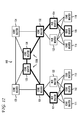
- FIG. 1 depicts a network having multiple routers in accordance with a preferred embodiment of the present invention
- FIG. 2 illustrates a path followed by a data packet in a network that originates at the customer router and has a destination of another customer router;
- FIGS. 3A-B depict exemplary routing loops that can occur in a network
- FIG. 4 depicts the implementation of a traceroute operation in a network
- FIGS. 5A-B illustrate the TTL expiries that can occur from traceroute activity in a network
- FIG. 6 is a flow diagram that illustrates a preferred embodiment of the present invention for detecting a routing loop or a TTL expiry attack
- FIG. 7 is a flow diagram illustrating a preferred embodiment for determining whether the TTL expiries are the result of traceroute activity, a routing loop, or a TTL expiry attack;
- FIGS. 8-9 are flow diagrams illustrating the preferred mathematical operations performed to determine whether there is traceroute activity, a routing loop, or a TTL expiry attack;
- FIGS. 10-12 depict various signatures that can be used to determine whether a routing loop or a TTL expiry attack exists.
- FIG. 13 depicts a preferred embodiment of a monitoring unit for implementing preferred embodiments of the present invention.
- TTL refers to a value associated with a data packet that is used to determine when the data packet expires.
- a TTL expiry attack occurs when one or more data packets have a TTL value that result in TTL expiries at the incoming interface of a router.
- a network such as an Internet Protocol (IP) network or a Multi Protocol Label Switched (MPLS) network can include a number of routers through which customer routers can communicate.
- IP Internet Protocol
- MPLS Multi Protocol Label Switched
- the preferred embodiments can detect the routing loops and the TTL expiry attacks based on a relationship, such as a difference, between TTL expiries occurring on two or more routers in the network. To achieve this, the preferred embodiments can query the routers in a network to obtain a quantity of TTL expiries occurring on incoming interfaces of the routers in a given time interval. For a given incoming interface of a router the quantity can be the difference between the TTL expiry counts at the end and beginning of the time interval.
- TTL expiries occurring on the incoming interface refers to TTL expiries caused by packets entering the router via the given interface.
- the quantity of TTL expiries on the incoming interfaces of a router during a given time interval can be summed.
- the quantity of TTL expiries occurring during the same time interval on incoming interfaces of other routers that are connected to the first router can be summed.
- the preferred embodiments can perform mathematical operations using the sums to detect a routing loop or a TTL expiry attack.
- the preferred embodiments can distinguish between traceroute activity, routing loops, or TTL expiry attacks.
- efficient detection of routing loops and TTL expiry attacks, as well as, separation of transient routing loops from persistent routing loops can be achieved using varying detection resolutions.
- the preferred embodiments detect routing loops or TTL expiry attacks for a router and/or a group of routers. The preferred embodiments can determine which router or routers are involved in a routing loop.
- FIG. 1 depicts an exemplary telecommunications network 100 .
- the network 100 can include edge routers 111 - 116 , hub routers 121 - 124 , and core routers 131 - 136 , the implementation of each being generally know to those skilled in the art.
- Customers typically connect to the network 100 via the edge routers 111 - 116 .
- a customer router 141 can connect to the edge router 111 and a customer router 142 can connect to the edge router 116 to allow each customer router 141 - 142 to communicate with each other and with other customer routers connected to the network 100 .
- Data packets can be transmitted over the network 100 . These data packets include, for example, a destination address, data, and a header.
- the destination of the data packet is generally a customer router (e.g., customer routers 141 - 142 ).
- the path that the data packet travels is generally formed based on the destination.
- Data packets generally contain a header that includes a time-to-live (TTL) value.
- TTL time-to-live
- the initial TTL value defines the maximum number of routers a packet can traverse to reach its destination. Each time the data packet passes through a router, the TTL value is decremented by one (1). If the destination is not reached before the TTL value reaches 1, the data packet is discarded.
- the router When a router receives a packet whose TTL value is 1, the router does not forward such a packet. If such a packet is destined for another router, the router that received the packet with a TTL value of one (1) drops the packet and sends a TTL expiry message to the router that originated the packet. Such expiration is referred to herein as a “TTL expiry.”
- TTL expiry Such expiration is referred to herein as a “TTL expiry.”
- the TTL value is generally set to as large a value as possible so that the TTL value of the data packet does not expire before reaching the destination.
- the destination of a packet can be a directly connected router. In this case, the TTL value of the packet received by the directly connected router can be one (1) so that the data packet stops at this router.
- the TTL value is set to its maximum value, the data packet reaches the intended destination. When a data packet does not reach the intended destination, an exception is said to have occurred.
- the customer router 141 may desire to transmit one or more data packets to the customer router 142 .
- a path 210 can be formed to include the edge router 111 , hub router 121 , core router 131 , core router 135 , core router 136 , core router 132 , hub router 124 , and edge router 116 .
- the path 210 can be the preferred path for communications between the customer router 141 and the customer router 142 .
- the network may implement one or more alternative paths. So to transmit a data packet from the customer router 141 to the customer router 142 , the data packet traverses eight (8) routers in the network 100 . As such, the TTL value is decremented eight (8) times along the path 210 as the data packet passes through the routers on the path 210 .
- TTL expiry signal can be transmitted from the router, in which the TTL expiration occurred, to the customer router 141 to notify the customer router 141 that TTL expiry has occurred.
- expirations are exceptions and can result from configuration errors, hardware or software errors, or due to a low TTL value intentionally specified by an attacker.
- Incorrectly specified TTL values can result in a TTL expiry attack on one or more routers in the network 100 . For example, if multiple data packets have a TTL value so that the data packets expire in a single router, that router will experience a large quantity of TTL expiries and may become overwhelmed causing the router to operate abnormally.
- routing loops can cause TTL expiry of packets caught in the loop. This is because the TTL value is a safeguard against network meltdowns during persistent routing loops. As a result of the TTL value, when a routing loop exists, data traffic in the network does not loop endlessly. Without this safeguard routing loops could exhaust the capacity of the routers involved in the routing loop.
- FIG. 3A depicts an exemplary routing loop 300 that can be formed in the network 100 .
- the routing loop 300 occurs only when the customer router 141 intends to communicate with a customer router (e.g., customer router 142 ) connected to edge router 116 .
- the customer router 141 can send data packets, for example, having the customer router 142 as the destination.
- the data packet can pass through the edge router 111 , hub router 121 , core router 131 , core router 135 , core router 136 , and core router 132 , as it normally would to reach the customer router 142 .
- the core router 132 can have a configuration error, hardware error, and/or a software error.
- the core router 132 sends the data packet to the core router 131 instead of the hub router 124 , which would normally receive the data packet.
- the core router 131 Upon receiving the data packet again, the core router 131 appropriately sends the data packet to the core router 135 forming the routing loop 300 .
- the core router 132 corrects the error in a relatively short time and data packets from the customer router 141 sent subsequent to the correction can reach the customer router 142 , which represents the destination. In a persistent routing loop, however, the data packets continue around the routing loop 300 until there is a TTL expiry.
- the routing loop 300 ( FIG. 3A ) a smaller quantity of TTL expiry packets would be seen on the routers along the loop, while for the routing loop 310 ( FIG. 3B ) there would be a large quantity of TTL expiries on the routers along the loop. Furthermore, for the routing loop 300 , the TTL expiries are likely to be concentrated on a few of the routers along the loop, while for the routing loop 310 the TTL expiries can be distributed among the routers along the routing loop.
- the customer router 141 may wish to determine the path traveled by data packets destined for the customer router 142 .
- the customer router 141 can set the TTL value to one (1) so that the traceroute packet, D 1 , enters the edge router 111 and simultaneously expires.
- the edge router 111 sends a TTL expiry signal, d 1 , to the customer router 141 , which uses the signal to determine the first router in the path 210 ( FIG. 2 ).
- the customer router 141 can set the TTL value to two (2) so that the traceroute packet, D 2 , passes through the edge router 111 and enters the hub router 121 where it expires.
- the hub router 121 sends a TTL expiry signal, d 2 , to the customer router 141 , which uses the signal to determine the second router in the path 210 . This iterative process can continue until the traceroute packet reaches the customer router 142 .
- Customer traceroute activity can cause TTL expiry on some or all of the routers in a carrier network. In the core of a large carrier network, the amount of TTL expiry due to customer traceroute activity can be substantial.
- TTL expiries can occur for several reasons, such as traceroute operations, routing loops and TTL expiry attacks. As a result, using the quantity of TTL expiries on a particular router by itself is generally not sufficient to detect the existence of a routing loop.
- the core router 135 of the network 100 can have a quantity of TTL expiries at its incoming interface as a result of the traceroute operation.
- a first traceroute operation can send a traceroute packet, A 1 , that has a TTL value of one (1) upon entering the core router 135 .
- a TTL expiry, T 1 occurs at the incoming interface of the core router 135 .
- a traceroute packet, A 2 can be sent with a TTL value that is one (1) greater than the previous TTL value so that the traceroute packet, A 2 , reaches the core router 136 with a TTL value of one (1).
- a TTL expiry, t 1 occurs at the incoming interface of the core router 136 .
- a second traceroute operation can be implemented by another customer router.
- a traceroute packet, B 1 from the second traceroute operation can reach the core router 135 with a TTL value equal to one (1) resulting in a TTL expiry, T 2 , at the incoming interface of the core router 135 .
- a subsequent iteration of the second traceroute operation can increment the TTL value by one (1) so that the traceroute packet, B 2 , reaches the core router 136 with a TTL value of one (1) resulting in a TTL expiry, t 2 , at the incoming interface of the core router 136 .
- a third traceroute operation can be implemented by another customer router.
- a data packet, C 1 from the third traceroute operation can reach the core router 135 with a TTL value equal to one (1) resulting in a TTL expiry, T 3 , at the incoming interface of the core router 135 .
- a subsequent iteration of the third traceroute operation can increment the TTL value by one (1) so that the traceroute packet, C 2 , reaches the core router 131 with a TTL value of one (1) resulting in a TTL expiry, t 3 , at the incoming interface of the core router 131 .
- a query of the incoming interface for the core router 135 identifies that three (3) TTL expiries (T 1 , T 2 , and T 3 ) occurred at the incoming interface of the core router 135 .
- a query of the directly connected incoming interface for the core router 136 connected to the core router 135 identifies that two (2) TTL expiries (t 1 and t 2 ) occurred.
- a query of the core router 131 identifies one (1) TTL expiry (t 3 ) occurred at the directly connected incoming interface of the core router 131 connected to the core router 135 .
- T(n) represents the TTL expiries at the incoming interface of a router during a given time interval
- t(m) represents the TTL expiries occurring at other routers on the incoming interfaces directly connected to the first router during the given time interval.
- TTL expiries are caused by a routing loop or a TTL expiry attack. This can be represented mathematically as follows: ( T 1 +T 2 +. . . +Tn ) ⁇ ( t 1 +t 2 +. . . +tm ) ⁇ 0; or (4) ⁇ T ( n ) ⁇ t ( m ). (5)
- a traceroute packet, X 2 can be sent with a TTL value that is incremented by one (1) so that the traceroute packet, X 2 , reaches the core router 136 with a TTL value of one (1).
- a TTL expiry, T 1 a occurs at the incoming interface of the core router 136 .
- the TTL value can again be incremented by one (1) so that the traceroute packet, X 3 , has a TTL value of one when entering the core router 132 . This results in a TTL expiry, t 1 , at the incoming interface of the core router 132 .
- a second traceroute operation can be implemented by another customer router.
- a traceroute packet, Y 1 from the second traceroute operation can reach the core router 136 with a TTL value equal to one (1) resulting in a TTL expiry, T 2 , at the incoming interface of the core router 136 .
- a subsequent iteration of the second traceroute operation can increment the TTL value by one (1) so that the traceroute packet, Y 2 , reaches the core router 135 with a TTL value of one (1) resulting in a TTL expiry, T 2 a , at the incoming interface of the core router 135 .
- the TTL value can again be incremented so that the traceroute packet, X 3 , reaches the core router 133 with a TTL value of one (1). This results in a TTL expiry, t 2 , at the incoming interface of the core router 133 .
- T 1 +T 2 t 1 +t 2.
- the sum of TTL expiries occurring at the incoming interfaces of the routers (e.g., core routers 135 and 136 ) in the group 510 is substantially equal to the sum of the TTL expiries at the directly connected incoming interfaces of the routers (e.g., core routers 13 1 - 134 ) that connect to the routers in the group 510 .
- the number of routers in the group can be specified so that one or more routers are included in the group.
- the size of a group can be statically assigned or dynamically assigned.
- the condition where the sum of TTL expiries in a router e.g., core router 135 ) does not equal the sum of TTL expiries in other routers (core routers 131 , 133 , and 136 ) connected to the router may not indicate the existence of a routing loop or a TTL expiry attack, but rather some mismatch in the network due to afore-mentioned causes.
- a threshold difference d.
- the threshold difference, d requires the difference between the sum of TTL expiries, T, on incoming interfaces of a router (e.g., core router 135 ) to differ from the sum of the TTL expiries, t, on incoming interfaces of other routers (e.g., core routers 131 , 133 , and 136 ) that directly connect to the router by an amount that is less than the threshold difference, d, before it can be determined that no routing loop or TTL expiry attacks exist.
- This can be represented mathematically as follows:
- FIG. 6 is a flow diagram illustrating a preferred embodiment of the present invention for detecting a routing loop or a TTL expiry attack.
- a monitoring unit can query one or more routers in a network using techniques known to those skilled in the art (step 600 ). Some or all of the routers in the network can be configured to be responsive to this query.
- the query can request a quantity of TTL expiries that occurred in one or more routers (step 610 ).
- the query can request the quantity of TTL expiries occurring at the incoming interface of routers (e.g., the core routers 131 - 136 ) in a network. In this manner, the routers of a network can be monitored to periodically track the quantity of TTL expiries occurring in the network.
- the monitoring unit can query the routers every 5 minutes.
- the routers can respond to the query by providing the monitoring unit with the quantity of TTL expiries for each router (step 620 ).
- the monitoring unit can determine the TTL expiries for incoming interfaces that occurred during the current time interval by taking the difference between the most recent and previous TTL expiry counts that are reported (step 630 ).
- routers report the cumulative TTL expiry counts.
- the monitoring unit can use these quantities to determine whether the TTL expiries for one or more of the routers is from traceroute activity, a routing loop, or a TTL expiry attack (step 640 ).
- the monitoring unit uses TTL expiry quantities from multiple time intervals to distinguish between persistent and transient routing loops.
- the monitoring unit determines that a routing loop existed in a time interval, but did not exist in a subsequent time interval, the monitoring unit can determine that a transient routing loop existed.
- a notification can be issued to preferably notify an operator or an automated diagnostic system (step 650 ). The operator may be able to discern visual patterns easily and diagnose the situation more efficiently.
- the monitoring unit captures the TTL expiries on router interfaces in a substantially simultaneous manner.
- the scripts can poll the routers at regular or irregular intervals to request the quantity of TTL expiries occurring at the routers.
- the threshold difference can be used to take into account the dynamic nature of TTL expiries and non-simultaneous captures by allowing a specified threshold difference between the sums before determining a persistent, rather than a transient routing loop or TTL expiry attack is occurring.
- the monitoring unit can distinguish between transient routing loops that are resolved in a relatively short period of time and persistent routing loops that continue for a relatively long period of time. Therefore, the preferred embodiments of the present invention can isolate the persistent routing loops, while disregarding the transient routing loops.
- the monitoring unit can also develop historical data associated with one or more of the routers in the network based on queries that were made to the routers. Historical data represents data from past operation of the routers. The quantity of TTL expiries can be compared to quantities of TTL expiries from historical data, which can provide further evidence of a persistent, rather than a transient routing loop or a TTL expiry attack.
- the resolution for detecting routing loops can depend on the number of routers included in a group.
- the group 510 that includes the core routers 135 and 136 can determine that the core router 135 and/or the core router 136 are involved in a routing loop.
- the group includes core routers 131 - 136 , it can be determined that some, none, or all of the routers are involved in a routing loop, but it may not be possible to determine which of the routers are actually involved in the routing loop.
- the monitoring unit can use a group including a large number of routers to monitor a certain area in the network. Once the monitoring unit determines that one or more of the routers in the group are involved in a routing loop, the monitoring unit may reduce the number of routers in the group to further isolate the routing loop to a smaller number of routers. This process can be performed iteratively until the routers involved in the routing loop are found.
- FIG. 7 is a flow diagram illustrating a preferred embodiment for determining whether the TTL expiries are the result of traceroute activity, a routing loop, or a TTL expiry attack.
- the monitoring unit can calculate the sum of TTL expiries at the incoming interface of a router or at the incoming interface of a group of routers occurring in the current time interval (step 702 ).
- the quantity of TTL expiries received by the monitoring unit may be a pre-calculated sum of TTL expiries for that router.
- the sum of TTL expiries at the incoming interfaces of other routers that are directly connected to the router or group of routers is also calculated (step 704 ).
- a mathematical operation is performed on the sums to distinguish between traceroute activity and a routing loop or a TTL expiry attack (step 706 ).
- the mathematical operation preferably is in the form of a difference between the sum of TTL expiries at the incoming interfaces of a router (e.g., core router 135 ) or at the incoming interfaces of a group (e.g., group 510 ) of routers and the sum of TTL expiries at the directly connected incoming interfaces of other routers (e.g., core routers 131 - 134 ) in the network occurring during the current time interval (step 832 ). If the difference is not zero or exceeds a specified threshold (step 836 ), the monitoring unit determines there is a persistent routing loop or a TTL expiry attack (step 836 ). A signature may be used to distinguish between a persistent routing loop and a TTL expiry attack (step 838 ). Otherwise, the monitoring unit determines that the TTL expiries are the result of traceroute activity or a transient routing loop (step 840 ).
- the mathematical operation can be in the form of a comparison between the sum of TTL expiries at the incoming interface of a router (e.g., core router 135 ) or at the incoming interface of a group (e.g., group 510 ) of routers and the sum of TTL expiries at the directly connected incoming interfaces of other routers (e.g., core routers 131 - 134 ) in the network (step 932 ) occurring in the current time interval. If the sums are equal or within a threshold (step 934 ), the monitoring unit determines that the TTL expiries are the result of traceroute activity or a transient routing loop (step 936 ). Otherwise, the monitoring unit determines there is a persistent routing loop or a TTL expiry attack (step 938 ). A signature may be used to distinguish between a persistent routing loop and a TTL expiry attack (step 940 ).
- the processes depicted in FIG. 6-9 can be preformed to monitor routers of interest in the network.
- the processes in FIGS. 6-9 can be implemented for the core routers 131 - 136 so that routing loops and TTL expiry attacks can be detected for the core routers 131 - 136 .
- the number of routers that are monitored can be varied.
- a service provider may wish to detect a routing loop in a network and may wish to isolate each of the routers involved in the routing loop to perform further diagnostic and/or resolve the routing loop.
- the monitoring unit may monitor some or all of the routers in the network and vary the resolution of monitoring using router groups until a region in the network is identified as not satisfying the equations described above.
- the monitoring unit can further determine whether there is a persistent routing loop or a TTL expiry attack automatically based on signatures.
- a signature represents a pattern in the network of routers that do not satisfy the principle of conservation associated with traceroute activity, which can be represented by equations (3) or (7).
- the monitoring unit can provide an operator with a textual and/or graphical depiction of the signature on a display and the operator can manually determine whether a persistent routing loop or a TTL expiry attack exists.
- the routers that are monitored may be depicted and the depictions may be annotated with the sum of TTL expiries that have occurred on each corresponding router in the current time interval.
- the annotation may be textual and/or graphical. Examples of graphical annotations can include weighting the lines connecting the routers as well as the borders of the routers based on the sum of TTL expiries experience, providing a color scheme where the color of the routers are based on the relative level of TTL expiries occurring at each router, and/or highlighting the routers with TTL expiry exceptions.
- the service provider can detect that TTL expiries are not the result of traceroute activity, as discussed above, and then can determine which of the routers are involved in the TTL expiries exceptions.
- the monitoring unit determine that the core routers 135 and 136 do not follow the principle of conservation associated with traceroute activity, and therefore do not satisfy equation (3) or (7).
- the monitoring unit determines that the core routers are involved in a routing loop or a TTL expiry attack based on a signature 1000 .
- the monitoring unit can automatically determine or can display the signature 1000 (graphical or textually) so that an operator can manually determine whether the signature 1000 corresponds to a routing loop or TTL expiry.
- the monitoring unit or the operator can determine that a routing loop has formed between the core routers 135 and 136 .
- the core routers 135 and 136 and the connection between the core routers 135 and 136 can have a weighted (thicker) border than the other routers to identify the level of TTL expiries occurring at the core routers 135 and 136 .
- the weighting can vary based on the sum of TTL expiries at each monitored router.
- FIG. 11 depicts an exemplary signature 1100 of a TTL expiry attack.
- the core router 135 has been identified as not satisfying equation (3) or (7). However, no other routers, adjacent or otherwise, have been identified for not satisfying equation (3) or (7).
- the monitoring unit or the operator with the assistance of the monitoring unit or an operator can determine that there was a TTL expiry attack based on the signature 1100 .
- the core router 135 may be highlighted or otherwise annotated on the display. As a result, the monitoring unit can identify routers undergoing TTL expiry attacks using the signature.
- FIG. 12 depicts an exemplary signature 1200 of a routing loop that may involve multiple networks some of which are external to the service provider's network 100 .
- edge routers 112 and 115 , hub routers 121 and 124 , and core routers 131 , 132 , 135 , and 136 are identified as not satisfying equation (3) or (7).
- the monitoring unit or the operator with the assistance of the monitoring unit identifies a group of sequentially adjacent routers having the signature 1200 depicted in FIG. 12 . Based on this signature 1200 , the monitoring unit and/or the operator with the assistance of the monitoring unit can determine that these routers are involved in a routing loop that extends into multiple networks.
- the signature 1200 may be depicted using a color scheme where the sum of the TTL expiries correspond to specified colors or may be annotated in any suitable manner.
- the monitoring unit 1300 can be formed of a computing device, such as a mainframe, personal computer (PC), laptop computer, workstation, or the like.
- the monitoring unit 1300 includes a central processing unit (CPU) 1302 and a display device 1304 .
- the display device 1304 enables the monitoring unit 1300 to communicate directly with a user through a visual display.
- the monitoring unit 1300 can further include data entry device(s) 1306 , such as a keyboard, touch screen, and/or mouse.
- the monitoring unit 1300 can include storage 1308 for storing data and instructions.
- the storage 1308 can include such technologies as a floppy drive, hard drive, tape drive, Flash drive, optical drive, read only memory (ROM), random access memory (RAM), and the like.
- Applications such as an application 1310 for detecting routing loops and TTL expiry attacks based on TTL expiries as described above, can be resident in the storage 1308 .
- the application 1310 can include instructions for implementing those embodiments depicted in FIGS. 1-12 .
- the storage 1308 can be local or remote to the monitoring unit 1300 .
- the monitoring unit 1300 preferably includes a network interface 1312 for communicating with the network 100 .
- the CPU 1302 operates to run the application in storage 1308 by performing instructions therein and storing data resulting from the performed instructions, which may be presented to the user via the display 1304 .
- the data can include the quantity of TTL expiries occurring at the monitored routers which can be depicted textually or graphically to identify a signature for the operator
- the disclosed preferred embodiments can be used to monitor a set of inter-connected routers in a large carrier network to detect routing loops involving any of the monitored routers.
- the preferred embodiments avoid the “combinatorial explosion” of having to send probes from every edge router to every other edge router to detect routing loops involving the core routers.
- the preferred embodiments can be used to monitor all routers in a network since only the TTL expiry counts on the interfaces are needed.
Abstract
Description
T1+T2+T3=t1+t2+t3; or (1)
(T1+T2+T3)−(t1+t2+t3)=0. (2)
ΣT(n)=Σt(m), (3)
(T1+T2+. . . +Tn)−(t1+t2+. . . +tm)≠0; or (4)
ΣT(n)≠Σt(m). (5)
T1+T2=t1+t2. (6)
|ΣT(n)−Σt(m)|<d. (7)
Claims (17)
Priority Applications (2)
| Application Number | Priority Date | Filing Date | Title |
|---|---|---|---|
| US11/963,039 US7752666B2 (en) | 2007-12-21 | 2007-12-21 | Detection of routing loops based on time-to-live expiries |
| US12/779,546 US8045460B2 (en) | 2007-12-21 | 2010-05-13 | Detection of routing loops based on time-to-live expiries |
Applications Claiming Priority (1)
| Application Number | Priority Date | Filing Date | Title |
|---|---|---|---|
| US11/963,039 US7752666B2 (en) | 2007-12-21 | 2007-12-21 | Detection of routing loops based on time-to-live expiries |
Related Child Applications (1)
| Application Number | Title | Priority Date | Filing Date |
|---|---|---|---|
| US12/779,546 Continuation US8045460B2 (en) | 2007-12-21 | 2010-05-13 | Detection of routing loops based on time-to-live expiries |
Publications (2)
| Publication Number | Publication Date |
|---|---|
| US20090161567A1 US20090161567A1 (en) | 2009-06-25 |
| US7752666B2 true US7752666B2 (en) | 2010-07-06 |
Family
ID=40788495
Family Applications (2)
| Application Number | Title | Priority Date | Filing Date |
|---|---|---|---|
| US11/963,039 Expired - Fee Related US7752666B2 (en) | 2007-12-21 | 2007-12-21 | Detection of routing loops based on time-to-live expiries |
| US12/779,546 Expired - Fee Related US8045460B2 (en) | 2007-12-21 | 2010-05-13 | Detection of routing loops based on time-to-live expiries |
Family Applications After (1)
| Application Number | Title | Priority Date | Filing Date |
|---|---|---|---|
| US12/779,546 Expired - Fee Related US8045460B2 (en) | 2007-12-21 | 2010-05-13 | Detection of routing loops based on time-to-live expiries |
Country Status (1)
| Country | Link |
|---|---|
| US (2) | US7752666B2 (en) |
Cited By (6)
| Publication number | Priority date | Publication date | Assignee | Title |
|---|---|---|---|---|
| US20090282145A1 (en) * | 2008-03-07 | 2009-11-12 | Buffalo Inc. | Network device, method for specifying installation position of network device, and notification device |
| US20100242113A1 (en) * | 2007-12-21 | 2010-09-23 | At&T Labs, Inc. | Detection of routing loops based on time-to-live expiries |
| US8769373B2 (en) | 2010-03-22 | 2014-07-01 | Cleon L. Rogers, JR. | Method of identifying and protecting the integrity of a set of source data |
| US20160149800A1 (en) * | 2014-11-26 | 2016-05-26 | Huawei Technologies Co., Ltd. | Routing Loop Determining Method and Device |
| US9356956B2 (en) | 2013-06-06 | 2016-05-31 | Empire Technology Development Llc | Preventing network tomography in software defined datacenter networks |
| US9369477B2 (en) | 2014-05-29 | 2016-06-14 | Empire Technology Development Llc | Mitigation of path-based convergence attacks |
Families Citing this family (16)
| Publication number | Priority date | Publication date | Assignee | Title |
|---|---|---|---|---|
| US8902765B1 (en) * | 2010-02-25 | 2014-12-02 | Integrated Device Technology, Inc. | Method and apparatus for congestion and fault management with time-to-live |
| US9088496B2 (en) * | 2012-03-16 | 2015-07-21 | Brocade Communications Systems, Inc. | Packet tracing through control and data plane operations |
| JP2014013972A (en) * | 2012-07-03 | 2014-01-23 | Sony Corp | Communication device and communication method, communication system, and computer program |
| US9769078B2 (en) | 2013-11-05 | 2017-09-19 | Cisco Technology, Inc. | Dynamic flowlet prioritization |
| US9655232B2 (en) | 2013-11-05 | 2017-05-16 | Cisco Technology, Inc. | Spanning tree protocol (STP) optimization techniques |
| US9502111B2 (en) | 2013-11-05 | 2016-11-22 | Cisco Technology, Inc. | Weighted equal cost multipath routing |
| US10778584B2 (en) | 2013-11-05 | 2020-09-15 | Cisco Technology, Inc. | System and method for multi-path load balancing in network fabrics |
| US9374294B1 (en) | 2013-11-05 | 2016-06-21 | Cisco Technology, Inc. | On-demand learning in overlay networks |
| US9350648B2 (en) * | 2014-05-09 | 2016-05-24 | Huawei Technologies Co., Ltd. | System and method for loop suppression in transit networks |
| US10205670B2 (en) * | 2014-09-12 | 2019-02-12 | Qualcomm Incorporated | Selective storage and deletion in mobile content delivery networks |
| US9929937B2 (en) * | 2015-08-27 | 2018-03-27 | Dell Products L.P. | Layer 3 routing loop prevention system |
| CN106549820A (en) * | 2015-09-23 | 2017-03-29 | 阿里巴巴集团控股有限公司 | Recognize method, device, flow cleaning equipment and the system of network loop |
| US10432578B2 (en) | 2016-09-27 | 2019-10-01 | Cisco Technology, Inc. | Client address based forwarding of dynamic host configuration protocol response packets |
| US10454882B2 (en) | 2017-06-30 | 2019-10-22 | Cisco Technology, Inc. | DHCP in layer-3 overlay with anycast address support and network address transparency |
| CN107809351B (en) * | 2017-10-24 | 2022-05-10 | 南京贝伦思网络科技股份有限公司 | Method for detecting loop in bypass mode |
| US10992562B2 (en) * | 2017-12-29 | 2021-04-27 | Arista Networks, Inc. | System for network event detection and analysis |
Citations (8)
| Publication number | Priority date | Publication date | Assignee | Title |
|---|---|---|---|---|
| US5014262A (en) | 1990-01-02 | 1991-05-07 | At&T Bell Laboratories | Apparatus and method for detecting and eliminating call looping in a node-by-node routing network |
| US5371732A (en) | 1992-02-14 | 1994-12-06 | Koninklijke Ptt Nederland N.V. | Method of detecting a routing loop in a telecommunication network, telecommunication network for using the method, and detection means for use in the telecommunication network |
| US6363384B1 (en) | 1999-06-29 | 2002-03-26 | Wandel & Goltermann Technologies, Inc. | Expert system process flow |
| US6501754B1 (en) | 1997-08-08 | 2002-12-31 | Kabushiki Kaisha Toshiba | Scheme for label switched path loop detection at node device |
| US6526044B1 (en) | 1999-06-29 | 2003-02-25 | Wandel & Goltermann Technologies, Inc. | Real-time analysis through capture buffer with real-time historical data correlation |
| US6529954B1 (en) | 1999-06-29 | 2003-03-04 | Wandell & Goltermann Technologies, Inc. | Knowledge based expert analysis system |
| US20030145232A1 (en) * | 2002-01-31 | 2003-07-31 | Poletto Massimiliano Antonio | Denial of service attacks characterization |
| US20060013143A1 (en) * | 2004-07-14 | 2006-01-19 | Fujitsu Limited | Network looping detecting apparatus |
Family Cites Families (5)
| Publication number | Priority date | Publication date | Assignee | Title |
|---|---|---|---|---|
| US7082129B2 (en) * | 2002-04-29 | 2006-07-25 | International Business Machines Corporation | Secure method and system to prevent external unauthorized remotely initiated power up events in computer |
| US7568224B1 (en) * | 2004-12-06 | 2009-07-28 | Cisco Technology, Inc. | Authentication of SIP and RTP traffic |
| DE602004021043D1 (en) * | 2004-12-30 | 2009-06-18 | Telecom Italia Spa | METHOD AND SYSTEM FOR DETECTING ATTACHMENTS IN WIRELESS DATA COMMUNICATION NETWORKS |
| US8370937B2 (en) * | 2007-12-03 | 2013-02-05 | Cisco Technology, Inc. | Handling of DDoS attacks from NAT or proxy devices |
| US7752666B2 (en) * | 2007-12-21 | 2010-07-06 | At&T Labs, Inc. | Detection of routing loops based on time-to-live expiries |
-
2007
- 2007-12-21 US US11/963,039 patent/US7752666B2/en not_active Expired - Fee Related
-
2010
- 2010-05-13 US US12/779,546 patent/US8045460B2/en not_active Expired - Fee Related
Patent Citations (8)
| Publication number | Priority date | Publication date | Assignee | Title |
|---|---|---|---|---|
| US5014262A (en) | 1990-01-02 | 1991-05-07 | At&T Bell Laboratories | Apparatus and method for detecting and eliminating call looping in a node-by-node routing network |
| US5371732A (en) | 1992-02-14 | 1994-12-06 | Koninklijke Ptt Nederland N.V. | Method of detecting a routing loop in a telecommunication network, telecommunication network for using the method, and detection means for use in the telecommunication network |
| US6501754B1 (en) | 1997-08-08 | 2002-12-31 | Kabushiki Kaisha Toshiba | Scheme for label switched path loop detection at node device |
| US6363384B1 (en) | 1999-06-29 | 2002-03-26 | Wandel & Goltermann Technologies, Inc. | Expert system process flow |
| US6526044B1 (en) | 1999-06-29 | 2003-02-25 | Wandel & Goltermann Technologies, Inc. | Real-time analysis through capture buffer with real-time historical data correlation |
| US6529954B1 (en) | 1999-06-29 | 2003-03-04 | Wandell & Goltermann Technologies, Inc. | Knowledge based expert analysis system |
| US20030145232A1 (en) * | 2002-01-31 | 2003-07-31 | Poletto Massimiliano Antonio | Denial of service attacks characterization |
| US20060013143A1 (en) * | 2004-07-14 | 2006-01-19 | Fujitsu Limited | Network looping detecting apparatus |
Non-Patent Citations (1)
| Title |
|---|
| U. Hengartner, S. Moon, R. Mortier, C. Diot, "Detection and Analysis of Routing Loops in Packet Traces," Proceedings of 2nd Internet Measurement Workshop (IMW 2002), Marseille, France, pp. 107-112, Nov. 2002. |
Cited By (9)
| Publication number | Priority date | Publication date | Assignee | Title |
|---|---|---|---|---|
| US20100242113A1 (en) * | 2007-12-21 | 2010-09-23 | At&T Labs, Inc. | Detection of routing loops based on time-to-live expiries |
| US8045460B2 (en) * | 2007-12-21 | 2011-10-25 | At&T Intellectual Property I, Lp | Detection of routing loops based on time-to-live expiries |
| US20090282145A1 (en) * | 2008-03-07 | 2009-11-12 | Buffalo Inc. | Network device, method for specifying installation position of network device, and notification device |
| US8250208B2 (en) * | 2008-03-07 | 2012-08-21 | Buffalo Inc. | Network device, method for specifying installation position of network device, and notification device |
| US8769373B2 (en) | 2010-03-22 | 2014-07-01 | Cleon L. Rogers, JR. | Method of identifying and protecting the integrity of a set of source data |
| US9356956B2 (en) | 2013-06-06 | 2016-05-31 | Empire Technology Development Llc | Preventing network tomography in software defined datacenter networks |
| US9369477B2 (en) | 2014-05-29 | 2016-06-14 | Empire Technology Development Llc | Mitigation of path-based convergence attacks |
| US20160149800A1 (en) * | 2014-11-26 | 2016-05-26 | Huawei Technologies Co., Ltd. | Routing Loop Determining Method and Device |
| US10003524B2 (en) * | 2014-11-26 | 2018-06-19 | Huawei Technologies Co., Ltd. | Routing loop determining method and device |
Also Published As
| Publication number | Publication date |
|---|---|
| US8045460B2 (en) | 2011-10-25 |
| US20090161567A1 (en) | 2009-06-25 |
| US20100242113A1 (en) | 2010-09-23 |
Similar Documents
| Publication | Publication Date | Title |
|---|---|---|
| US7752666B2 (en) | Detection of routing loops based on time-to-live expiries | |
| Sherwood et al. | Discarte: a disjunctive internet cartographer | |
| EP1999890B1 (en) | Automated network congestion and trouble locator and corrector | |
| US10027562B2 (en) | Detecting network services based on network flow data | |
| CA2706581C (en) | System, method and program for determining failed routers in a network | |
| WO2021128977A1 (en) | Fault diagnosis method and apparatus | |
| JP5195953B2 (en) | Abnormal link estimation device, abnormal link estimation method, program, and abnormal link estimation system | |
| US20050108415A1 (en) | System and method for traffic analysis | |
| EP2795841B1 (en) | Method and arrangement for fault analysis in a multi-layer network | |
| JP4648838B2 (en) | Network monitoring support apparatus, network monitoring support method, and network monitoring support program | |
| US11711389B2 (en) | Scanner probe detection | |
| US20210400073A1 (en) | Malicious port scan detection using source profiles | |
| US11770396B2 (en) | Port scan detection using destination profiles | |
| US8441942B1 (en) | Method and apparatus for link level loop detection | |
| US10742672B2 (en) | Comparing metrics from different data flows to detect flaws in network data collection for anomaly detection | |
| JP2015535669A (en) | Monitoring encrypted sessions | |
| US20190349481A1 (en) | System and method for tracing a communications path over a network | |
| JP4422176B2 (en) | Traffic amount change cause identification method, system, program, and recording medium | |
| CN114465897A (en) | Method, device and system for monitoring data packets in service flow | |
| CN113904972B (en) | Path detection method and device, controller and PE (polyethylene) equipment | |
| EP3918762A1 (en) | Port scan detection | |
| Marder et al. | Vrfinder: Finding outbound addresses in traceroute | |
| US8042183B2 (en) | Method and apparatus for detecting computer-related attacks | |
| JP2005051579A (en) | Connection monitor system | |
| Watari et al. | A Method for Real-Time Identification of Malformed BGP Messages |
Legal Events
| Date | Code | Title | Description |
|---|---|---|---|
| AS | Assignment |
Owner name: AT&T LABS, INC.,TEXAS Free format text: ASSIGNMENT OF ASSIGNORS INTEREST;ASSIGNORS:JAYAWARDENA, THUSITHA;SHUGARD, WILLIAM J.;REEL/FRAME:020284/0589 Effective date: 20071115 Owner name: AT&T LABS, INC., TEXAS Free format text: ASSIGNMENT OF ASSIGNORS INTEREST;ASSIGNORS:JAYAWARDENA, THUSITHA;SHUGARD, WILLIAM J.;REEL/FRAME:020284/0589 Effective date: 20071115 |
|
| FEPP | Fee payment procedure |
Free format text: PAYOR NUMBER ASSIGNED (ORIGINAL EVENT CODE: ASPN); ENTITY STATUS OF PATENT OWNER: LARGE ENTITY Free format text: PAYER NUMBER DE-ASSIGNED (ORIGINAL EVENT CODE: RMPN); ENTITY STATUS OF PATENT OWNER: LARGE ENTITY |
|
| AS | Assignment |
Owner name: AT&T INTELLECTUAL PROPERTY I, L.P., GEORGIA Free format text: NUNC PRO TUNC ASSIGNMENT;ASSIGNOR:AT&T LABS, INC.;REEL/FRAME:026308/0484 Effective date: 20110511 |
|
| REMI | Maintenance fee reminder mailed | ||
| LAPS | Lapse for failure to pay maintenance fees | ||
| STCH | Information on status: patent discontinuation |
Free format text: PATENT EXPIRED DUE TO NONPAYMENT OF MAINTENANCE FEES UNDER 37 CFR 1.362 |
|
| FP | Lapsed due to failure to pay maintenance fee |
Effective date: 20140706 |