US7738465B2 - Packet forwarding device equipped with statistics collection device and statistics collection method - Google Patents
Packet forwarding device equipped with statistics collection device and statistics collection method Download PDFInfo
- Publication number
- US7738465B2 US7738465B2 US10/885,307 US88530704A US7738465B2 US 7738465 B2 US7738465 B2 US 7738465B2 US 88530704 A US88530704 A US 88530704A US 7738465 B2 US7738465 B2 US 7738465B2
- Authority
- US
- United States
- Prior art keywords
- search
- packet
- information
- flow
- header
- Prior art date
- Legal status (The legal status is an assumption and is not a legal conclusion. Google has not performed a legal analysis and makes no representation as to the accuracy of the status listed.)
- Expired - Fee Related, expires
Links
Images


Classifications
-
- H—ELECTRICITY
- H04—ELECTRIC COMMUNICATION TECHNIQUE
- H04L—TRANSMISSION OF DIGITAL INFORMATION, e.g. TELEGRAPHIC COMMUNICATION
- H04L43/00—Arrangements for monitoring or testing data switching networks
-
- H—ELECTRICITY
- H04—ELECTRIC COMMUNICATION TECHNIQUE
- H04L—TRANSMISSION OF DIGITAL INFORMATION, e.g. TELEGRAPHIC COMMUNICATION
- H04L43/00—Arrangements for monitoring or testing data switching networks
- H04L43/02—Capturing of monitoring data
- H04L43/022—Capturing of monitoring data by sampling
- H04L43/024—Capturing of monitoring data by sampling by adaptive sampling
-
- H—ELECTRICITY
- H04—ELECTRIC COMMUNICATION TECHNIQUE
- H04L—TRANSMISSION OF DIGITAL INFORMATION, e.g. TELEGRAPHIC COMMUNICATION
- H04L43/00—Arrangements for monitoring or testing data switching networks
- H04L43/02—Capturing of monitoring data
- H04L43/026—Capturing of monitoring data using flow identification
-
- H—ELECTRICITY
- H04—ELECTRIC COMMUNICATION TECHNIQUE
- H04L—TRANSMISSION OF DIGITAL INFORMATION, e.g. TELEGRAPHIC COMMUNICATION
- H04L43/00—Arrangements for monitoring or testing data switching networks
- H04L43/16—Threshold monitoring
Definitions
- the present invention relates to a statistics collection method for recording information such as the number of packets transmitted and the number of bytes, as well as a statistics collection device containing the statistics collection method and installed in a network.
- the Internet has become established as an important part of our social infrastructure and besides conventional Best_Effort type data communications, starts to communicate data needed to ensure communication quality such as transaction data for mainstream business operations and audio-video.
- the volume of data being communicated is also increasing along with the spread of lines for accessing broadband communications by way of technology such as ADSL (Asymmetric Digital Subscriber Line) and FTTH (Fiber To The Home).
- ADSL Asymmetric Digital Subscriber Line
- FTTH Fiber To The Home
- the carrier and ISP Internet Service Provider
- a network monitoring function for collecting and analyzing statistics on the communication data volume on the network.
- this communication data there is also a large need for a function for collecting and analyzing statistic information for each data group (hereafter flow) categorized into the data source and address, application and quality level, etc.
- the carrier and ISP can verify the quality assurance status when a communication quality assured service is provided.
- the carrier and ISP can also use limited network resources effectively to handle increased data volume using Traffic engineering (hereafter abbreviated to TE) technique.
- the carrier and ISP can also offer provisioning service which provides network resources speedily and timely to meet customer requests (bandwidth, quality of services), and can also detect and analyze network attacks, and can also carry out billing, etc.
- a flow statistics collection method in the technology of the related art for example is the cache method (related technology 1).
- the related art 1 technology is made up of multiple statistics collection devices distributed within the network and a collector device for collecting statistic information periodically reported from these multiple statistics collection devices and analyzing traffic over the entire network.
- a statistics collection device is a router that performs packet transfer in the network.
- the processing by the statistics collection device in the related art is described using a router as an example.
- the router incorporating a statistic collection function searches a flow table in which one or more combinations (hereafter called flow conditions) of packet headers are stored (or registered) for identifying the flow. If the packet matches the stored flow conditions, then a 1 is added to the packet number stored for that matching flow conditions. The byte count of the received packet stored for that matching flow condition is also increased in the same way. If results from the search of the flow table show no matching flow condition, then the received packet header information combination is newly stored in the flow table. A search is made at fixed periodic intervals of each flow condition stored in the flow table and aging processing is performed to delete flow conditions whose statistic information is unchanged from the previous search. To delete a flow condition, a packet with the corresponding statistic information is generated and the packet sent to the collector device.
- flow conditions one or more combinations
- the number of bits for the search key in the flow table search is usually large compared to the number of bits of the search key for the destination search made when the router forwards a packet. Therefore, shortening the time needed for the flow table search is difficult compared to the destination search. This fact signifies that flow table search time takes up a large part of the router's packet processing time. The flow table search process therefore causes packet forwarding performance to deteriorate when flow table search time is larger than the required packet forwarding processing time.
- routers containing high speed lines perform sampling of packets for flow table searches, according to a predetermined sampling rate and only make a flow table search of the sampled packets.
- JP-A No. 208945/2002 a technology for making routing table searches was disclosed in JP-A No. 208945/2002 (Related technology 3).
- the related technology 3 utilizes a stored path table capable of spanning a first memory made up of high speed memories such as a Content Addressable Memory (CAM), and a second memory with a slower search speed than the first memory but possessing a higher degree of entry integration.
- the related technology 3 is capable of making entry searches requiring a larger number of bits than can be set in the CAM at higher speeds than when utilizing only a RAM (Random Access Memory).
- the above described related technologies 1 and 2 have the following problems when handing ever-increasingly large amounts of data, and in quality assurance of important data.
- the search key for flow table that is a combination of multiple fields within the packet header has a larger number of bits compared to the search key for destination searches that is made up of only one field within the packet header or combinations of two fields.
- the number of flow conditions hereafter, number of flow entries
- the number of flow entries must also be several times larger than the number of entries in the destination table.
- Tree method For storing flow tables in a tree structure in the memory by utilizing Dynamic Random Access Memory (DRAM) or Static Ram (SRAM) having an inexpensive cost per bit.
- DRAM Dynamic Random Access Memory
- SRAM Static Ram
- Using the Tree method has the advantages that only a small number of memory chips are needed when storing information in a table made up of a large number of entries, the device has a low cost, and little installation space is needed in the device.
- multiple memory access lines are usually needed during a search so the search performance falls to only a fraction (less than a fifth or sixth) of that of the CAM method described next.
- the related art technology 2 provides the required packet transmit performance needed holding lines (port) with a high line speed by lowering the number of times flow table searches are made according to a preset sampling rate.
- This method performs packet sampling and is capable of finding statistical trends of each packet flow.
- this method cannot acquire an accurate number of received packets or a received byte count.
- This method performs TE and provisioning, network facility planning, and attack detection by finding the statistical flow data size using the sample statistical value.
- this method has problems because of use of sampling (sample statistical value) in cases for example where utilizing information shown by the network administrator to the network user regarding whether quality assurance is actually being performed on a network for a flow where quality assurance is needed, or when billing, where utilizing an accurate packet count or byte count is important.
- One method for making high speed searches where the search key has a large number of bits is a search method using CAM (hereafter, called the CAM method).
- the CAM method is capable of high speed searches of search key bit patterns and bit patterns recorded in the memory.
- the cost per bit is high compared to typical memories.
- Other problems with the CAM method are that the number of CAM chips increases when dealing with large numbers of entries so that the device cost becomes higher, and the available mounting surface area inside the device is inadequate, etc.
- Yet another problem is that power consumption is high since all bit patterns registered in the memory and the search key bit pattern are compared in parallel.
- the related art technology 3 discloses a method for high speed router searches of routing table. However it does not discuss flow table searches. In methods utilizing CAM and RAM, the time needed for accessing the RAM is added on to the time for the CAM method. Also, the same as with the Tree method when searching flow tables made up of a large number of entries in devices having lines (ports) with a high line speed, the time needed for searching the flow table becomes longer than the allowable packet forwarding processing time. In the related art technology 1 that searches all received packets in a flow table search, achieving the required packet processing performance is difficult.
- a first object of the present invention is to provide a packet forwarding method or a packet forwarding device capable of acquiring accurate statistic information on a flow requiring accurate statistic information even when the data size has increased and high speed packet forwarding processing is required.
- a second object of the present invention is to provide a packet forwarding method or a packet forwarding device capable of collecting statistics on a large number of flows, even when there has been a further increase in the volume of packets to transmit.
- the router of the present invention contains a first table and a means for searching the first table, a second table and a means for searching the second table, and a discrimination means for discriminating between (received) packets requiring collection of all statistic information and packets not requiring collection of all statistic information.
- the router of the invention also contains a search discrimination table to decide if the first table or the second table should be searched, and a means to search the search table—discrimination table.
- the means for searching the first table, the second table and the discrimination table may all be achieved with one search means.
- the router When the router receives a packet, besides performing the usual routing, the router searches the search table—discrimination table and decides whether to search the first table or the second table. When the router decides to search the first table search, a search is made of the first table and statistics matching the same flow conditions are rewritten.
- the received packets are separated prior to processing so the time required to process the packets is reduced compared to the case of collecting statistic information on all received packets.
- the accuracy of the collected statistic information is also improved for flows requiring total collection compared to the case of using sampling to collect statistic information from all packets.
- a decision to search or not search the second table is made according to the sampling rate that was set in the storage means.
- the second table search processor searches the second table, and statistics for corresponding flow conditions are rewritten.
- Sampling those packets belonging to the same flow conditions stored in the second table allows increasing the number of flow types capable of collecting statistic information having the same packet forwarding performance. Also, conditions for identifying an adequate flow with sampled statistical values are set in the discrimination table. Further, sampled values from a large number of flows can be collected without lowering the packet forwarding performance, by setting a sampling rate in the storage means at a level that will not lower the packet forwarding performance.
- FIG. 1 is a drawing showing the network structure comprised of routers for the statistics collection method of the present invention
- FIG. 2 is a diagram showing the structure of the packet received in FIG. 1 ;
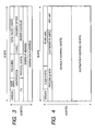
- FIG. 3 is a diagram showing the structure of the IPv4 header
- FIG. 4 is a diagram showing the structure of the IPv6 header
- FIG. 5 is a diagram showing the structure of the TCP header
- FIG. 6 is a diagram showing the structure of the UDP header
- FIG. 7 is a diagram showing an example of the flow condition structure for flow statistics collected by the router R 1 in FIG. 1 ;
- FIG. 9 is a block diagram of the structure of the router for the statistics collection method of the present invention.
- FIG. 10 is a block diagram showing the structure of the search processor within the router for the statistics collection method of the present invention.
- FIG. 11 is drawings showing the structure of a high-speed flow table within the router for the statistics collection method of the present invention.
- FIG. 12 is drawings showing the structure of a large scale flow table within the router for the statistics collection method of the present invention.
- FIG. 13 is a block diagram showing the sample discriminator within the router for the statistics collection method of the present invention.
- FIG. 16 is a drawing showing sample period (interval) table for each input port utilized in the sample discriminator of FIG. 14 ;
- FIG. 17 is a block diagram showing another sample discriminator within the router for the statistics collection method of the present invention.
- FIG. 18 is a drawing showing the structure of a high-speed flow table utilized in the sample discrimination method of the present invention.
- FIG. 19 is a block diagram showing another sample discriminator within the router for the statistics collection method of the present invention.
- FIG. 20 is a block diagram showing another sample discriminator within the router for the statistics collection method of the present invention.
- FIG. 21 is a drawing showing the structure of the random number table for each input port utilized in sample discriminator FIG. 20 ;
- FIG. 22 is a drawing showing the structure of the threshold table for each input port utilized in sample discriminator FIG. 20 ;
- FIG. 23 is a block diagram showing another sample discriminator within the router for the statistics collection method of the present invention.
- FIG. 24 is a drawing showing the structure of a high-speed flow table utilized in the sample discrimination method shown in FIG. 23 ;
- FIG. 25 is a block diagram showing the structure of another router for the statistics collection method of the present invention.
- FIG. 26 is a block diagram showing the structure of another router for the statistics collection method of the present invention.
- FIG. 27 is a block diagram showing the structure of the search processor within the router shown in FIG. 26 ;
- FIG. 28 is a block diagram of the structure of another router for the statistics collection method of the present invention.
- FIG. 29 is a table showing the structure of statistic information notification packet format utilized in the statistics collection device of the present invention.
- FIG. 30 is a concept drawing of the control console connected for setting the discriminator table of the statistics collection method of the present invention.
- FIG. 31 is a concept drawing of the control console connected for setting the discriminator table of the statistics collection method of the present invention.
- statistic information signifies processing the router must perform on received packets in order to acquire the specified statistic information as well the type of information the router must collect.
- the term “statistic information” used here is therefore different from the generally used meaning.
- FIG. 1 is a drawing showing a typical network structure made up of routers having the flow statistic collection function.
- the network shown in FIG. 1 is made up of terminals T1, T2, T3, T4, servers S1, S2, and routers R2, R3 each connected with the servers, and a router R1 connected by way of the ports C_T1, C_T2, C_T3, C_T4, C_R2, C_R3 with these terminals and servers.
- the packet belonging to the flow (hereafter flow 1) is sent from the server S1 to the terminal T1.
- the upper or host protocol within the IP (Internet Protocol) header in flow 1 is TCP (Transmission Control Protocol).
- TCP Transmission Control Protocol
- the TOS (Type of Service) within the IP header in flow 1 is TOS1.
- the source port number within the TCP header in flow 1 is SPRT1.
- the destination port number within the TCP header in flow 1 is DPRT1.
- the packet belonging to the flow (hereafter flow 2) is sent from the server S1 to the terminal T3.
- the upper or host protocol of this packet (flow 2) is TCP.
- the TOS is TOS1.
- the source port number is SPRT1.
- the destination port number is DPRT3.
- the packet belonging to the flow (hereafter called flow X3) is sent from the server S2 to the terminal T2.
- the upper or host protocol of this flow x3 is UDP (User Datagram Protocol).
- the TOS is TOS2.
- the source port number within the UDP header is DPRT2.
- the destination port number within the UDP header is DPRT2.
- the packet belonging to the flow (hereafter flow 4) is sent from the server S2 to the terminal T4.
- the upper or host protocol of this flow 4 is UDP (User Datagram Protocol).
- the TOS is TOS2.
- the source port number (within the UDP header) is SPRT2.
- the destination port number is DPRT4.
- FIG. 2 is a diagram showing the packet being sent or received.
- the packet here is made up of data and multiple header information for protocols in each layer of the OSI (Open System Interconnection) model. More specifically, the packet is made up of a layer 2 header ( 201 ), a layer 3 header ( 202 ), a layer 4 header ( 203 ), a data ( 204 ).
- Protocols such as Ethernet (registered trademark), ATM (Asynchronous Transfer Mode), MPLS (Multi_Protocol Label Switching) can be utilized as the layer 2 protocol.
- Protocols such as IP version 4 (hereafter, IPv4), IP version 6 (hereafter, IPv6) can be utilized as the layer 3 protocol.
- Protocols such as TCP, UDP can be utilized as the layer 4 protocol.
- FIG. 3 is a diagram showing the structure of an IPv4 header, utilizing the header of the layer 3 protocol as an example.
- This IPv4 header contains a ToS to indicate the transmit quality of the packet, a protocol showing the layer 4 protocol, an IP address (source IP address) for the source terminal, and an IP address (destination IP address) for the destination terminal.
- the ToS and the protocol are 8 bits.
- the source IP address and the destination IP address are both 32 bits.
- FIG. 4 is a diagram showing the structure of an IPv6 header, utilizing the header of the layer 3 protocol as an example.
- This IPv6 header stores a class indicating the transmit quality of the packet, the following header number for identifying the next header type, source IP address and destination IP address.
- the next header is a layer 4 protocol such as TCP or UDP
- a value showing the layer 4 protocol is stored in the next header number.
- the class is eight bits.
- the next header number is eight bits, the source IP address and the destination IP address are both 128 bits.
- FIG. 5 is a diagram showing the structure of the TCP header using the header of a layer 4 protocol as an example.
- the TCP header contains a source port number and a destination port number as a logic port number for identifying the host (upper) application layer.
- the source port number and the destination port number are both 16 bits.
- FIG. 6 is a diagram showing the structure of the UDP header using the header of a layer 4 protocol as an example.
- the UDP header contains a source port number and a destination port number, the same as does the TCP header.
- the source port number and the destination port number are both 16 bits.
- FIG. 7 is a diagram showing flow conditions for flow statistics collected in the router R 1 of FIG. 1 .
- the example in FIG. 7 shows the source IP address ( 701 ), the destination IP address ( 702 ), the host protocol ( 703 ), the TOS ( 704 ) within the UDP header, and the source port number ( 705 ) and destination port number ( 706 ) as the flow conditions within the TCP or IP header.
- the combination of header values utilized as the flow conditions here are only a present embodiment and combinations of other values may also be utilized.
- FIG. 8 is an example of statistic information collected for each flow condition.
- the statistic information for collection is the number of received packets belonging to each flow (hereafter, called the packet count) ( 801 ), the total sum of the number of bytes for packet belonging to that flow (hereafter called the byte count) ( 802 ), the port number where packets for each flow are input ( 803 ), the port number where packets for each flow are output ( 804 ), and other information ( 805 ).
- the flow 1 and flow 3 require quality assurance.
- the flow 1 and flow 3 require quality assurance and are flows requiring accurate statistic information.
- the flow 2 and flow 3 are flows with adequate statistic sampled values.
- the statistic information shown in FIG. 8 is held within the packet forwarding device in a format such as a table.
- the received packet is analyzed, the flow conditions extracted, and a search key used to search for flow conditions matching the statistic information held within the device.
- the received packet is processed as needed based on the hits found in the statistic information. Information acquired from the processing results is stored in the device. The process is described next in detail.
- the control section 905 is connected to the packet receiver processor 901 , a search processor 1000 , a large scale flow table search processor 902 , and packet transmit processor 904 and makes the settings for each of these processors.
- a method for operating the elements 901 through 905 , 1000 , 1100 and 1200 in the router 900 for example is to operate each processor on a single dedicated LSI (device) and connect each processor alternately to the dedicated LSI (device).
- Another method is to operate multiple processors on a single dedicated LSI, connecting that dedicated LSI alternately to each of the multiple processors.
- Another method is to operate the elements in the router 900 on a general-purpose MPU (Micro Processing Unit) or NP (Network Processor).
- a CAM Content Addressable Memory
- a DRAM capable of storing multiple flow entries and having a small chip size per bit, as well as an inexpensive cost per bit may be utilized as the memory for storing the large scale flow table 1200 .
- the router 900 shown in FIG. 9 is a structure with a search table-discrimination table within the high-speed flow table for deciding the high speed flow table processing and large scale flow table processing.
- the search processor 1000 searches the search table-discrimination table within the high-speed flow table at the same time as it searches the high-speed flow table, and decides whether or not to search the large scale flow table.
- the router of the present embodiment is comprised of an architecture for searching always first searching the high-speed search table.
- the architecture can contain a function for deciding whether to search either the high-speed search table of the large search table.
- an architecture can be achieved wherein the packet receive processor 901 decides whether to transmit the packet to the large search processor or the search processor.
- the header information for the packet must always be transmitted to the search processor.
- a routing table search must also be made by the search processor.
- a control console can be installed in the router as shown in FIG. 9 and information stored in the discriminator table can be set there as needed.
- a concept view of the control console 3000 connection for setting the discrimination table within the router, and the router 900 for the statistic collection function of the present invention are shown in FIG. 30 .
- a means for selecting the desired location for displayed contents and changing the displayed contents of the table by way of a display screen 3001 for displaying the contents of the table, and the mouse 3002 , and the keyboard 3000 is installed in the control console 3000 .
- this console may also be connected by way of a network to the router 900 for the statistic collection function of the present invention.
- the function of the console may also be held in a collector device, and that collector device may set information stored in the discrimination table, into the router 900 .
- FIG. 10 shows a typical structure of the search processor 1000 in the router 900 of FIG. 9 .
- the search processor 1000 is made up of a header information storage section 1001 , a high-speed flow table search processor 1002 , the routing table search processor 1003 , the sample discrimination section 1300 , the search result generator 1004 , and the flow register-delete processor 1005 .
- FIG. 11 shows the structure of the high-speed flow table 1100 of FIG. 9 and FIG. 10 .
- the flow table 1100 holds one or more entries comprised of a flow entry number field 1101 , a flow condition field 1102 , a search result field 1103 , and a statistic information field 1104 .
- the flow entry number field 1101 is information relating to a flow condition field 1102 , a search result field 1103 , a statistic information field 1104 and in some cases may be unnecessary depending on the table structure.
- the flow conditions identical to those shown in FIG. 7 are one example of the flow condition field 1102 .
- the example of the flow condition field 1102 shown in FIG. 11 is a combination of the source IP address, the destination IP address, the host (upper layer) protocol, the TOS, the source port number, and the destination source port number.
- the flow 1 and the flow 3 as flows requiring the accurate statistics shown in FIG. 7 are respectively set as the flow entry numbers f1, f2 in the high-speed flow table 1100 .
- the search table-discrimination table is contained within the high-speed flow table. More specifically, a flow entry number f3 is set in order to set instructions to search the large search table for flow 2, and flow 4 adequately sampled for the statistics shown in FIG. 7 .
- the “*” shown in the fields for the source IP address field, destination IP address field, host (upper layer) protocol field, TOS field, and destination port number field for flow conditions matching those in the flow entry number f3, indicates that the value is not utilized as a flow condition.
- the entry in the flow entry number f3 will be a hit when the source port numbers for flow 2 and flow 4 are both SPRT2.
- the search result field 1103 is comprised of a sample command flag 1103 _ 1 and sampling rate 1103 _ 2 .
- the sampling rate here is frequency information as to how often (at what frequency) statistic collection is performed.
- a “1” setting in the sample command flag 1103 _ 1 indicates sampling and copying of the packet hit into the large table search processor.
- a setting of “0” indicates no sampling or copying is performed.
- the sampling rate is set in the sampling rate 1103 _ 2 when copying the packet hit in each flow into the large scale flow table search processor.
- the sampling rate 1103 _ 2 setting is valid when a “1” is set in the sample command flag 1103 _ 1 .
- the sample command flag set to “1” and the sampling rate value set to “ 1/1000” indicate the search results of the flow entry number (No.) f3 specifying a large scale flow table search.
- a sampling rate value of “ 1/1000”, indicates a large scale flow table search made for one packet among 1,000 packets that were received.
- the sampling rate 1103 _ 2 may at times be used for other information according to the formula as described later on.
- the example in the statistic information field 1104 shows the information identical to the statistic information shown in FIG. 7 .
- the example in the statistic information field in FIG. 11 is comprised of a packet count, a byte count, the input port number, the output port number, and other information.
- the “_” in the input port number and output port number of the flow entry number f3 indicate a value with no meaning.
- the flow entry numbers f1, f2 set in FIG. 11 are not set in particular by the router 900 administrator and may be automatically set in the flow register-delete processor 1005 .
- the entry for flow entry number f3 for commanding a large scale flow table search specified in FIG. 11 must be set beforehand by the router 900 administrator. The operation for registering and deleting flows by the flow register-delete processor 1005 is described later.
- FIG. 12 is drawings showing the structure of the large scale flow table 1200 of FIG. 9 .
- the large scale flow table 1200 is made up of one or more entries comprised of a flow entry number 1201 , a flow condition 1202 , and statistic information 1203 .
- the flow entry number 1201 is information relating to the flow condition 1202 , a statistic information 1203 , and in some cases may be unnecessary depending on the table structure.
- the flow conditions identical to those shown in FIG. 7 are one example of the flow condition 1202 .
- the example of the flow condition 1202 shown in FIG. 12 is a combination of the source IP address, the destination IP address, the host (upper layer) protocol, the TOS, the source port number, and the destination source port number.
- the flow 2 and flow 4 with adequate sample statistical values shown in FIG. 7 are respectively set as the flow entry numbers f4, f5 in the large scale flow table 1200 .
- the statistic information 1203 is shown with statistic information identical to that shown in FIG. 7 .
- the example for statistic information 1203 in FIG. 12 is comprised of a packet count, a byte count, the input port number, the output port number, and other information.
- the entries for flow entry number f4, f5 set in FIG. 12 are not set in particular by the router 900 administrator and may be automatically set by the flow register-delete processor (not shown in drawing) within the large scale flow table search processor.
- the registering and deleting operation of the flow register-delete processor within the large scale flow table search processor 902 is the same processing as the flow register-delete processing of FIG. 10 and is described later on.
- FIG. 9 The operation when the router 900 receives a packet is described next using FIG. 9 , FIG. 10 , FIG. 11 and FIG. 12 .
- the router 900 operation when receiving a packet belonging to the flow 1 shown in FIG. 7 is described first.
- the packet receive processor 901 that received the packet input from the input port first of all attaches information within the device relating to receive processing such as an input port number (No.) to the packet as a header within the device.
- the processor 901 then accumulates the packet data and extracts header information such as the header within the device, layer 2 header, layer 3 header, and layer 4 header and sends it to the search processor 1000 .
- the header information storage section 1001 in FIG. 10 temporarily accumulates header information received from the packet receive processor 901 and sends it to the routing table search processor 1003 , high-speed flow table search processor 1002 , and the flow register-delete processor 1005 .
- the routing table search processor 1003 that received the header information, extracts the required information from that header information and generates a search key. The processor 1003 then searches the routing table 903 using that generated search key. The routing table search processor 1003 sends destination information such as the output port number as search results from the routing table 903 , to the high-speed flow table 1002 and search result generator 1004 .
- the high-speed flow table search processor 1002 that received the header information extracts the source IP address, destination IP address, host (upper layer) protocol, TOS, source port number, and destination port number from that header information and generates a search key. The processor 1002 then searches the high speed flow table 1100 using that search key. In the case of the present embodiment, the received packet belongs to the flow 1 so the search key matches the flow entry number f1 of high speed flow table 1100 . Therefore, the high-speed flow table search processor 1002 acquires the two results of a sample command flag “1” and an invalid sampling rate, and sets the two values in the search results for the flow entry number f1. The high-speed flow table search processor 1002 sends these search results to the sample discrimination table 1300 .
- the high-speed flow table search processor 1002 rewrites the statistic information field 1104 for the flow entry number f1 that matched the search key flow conditions. More specifically, a 1 is added to the packet count for the flow entry number f1, the byte count of the received packet is added to the byte count, the input port number within that device header is recorded in the input port number, and the output port number received from the routing table search processor 1003 is recorded in the output port number.
- the sample discrimination table 1300 that received the search results from the high-speed flow table search processor 1002 decides whether or not to generate a copy in the large scale flow table search processor 902 based on those search results, and sends a copy command to the search result generator 1004 . More specifically, a decision not to make a copy is made when the sample command flag in the search results is a “0”. When the sample command flag is a “1”, a decision is made on whether or not to generate a copy utilizing the sampling rate search results. In this example, the sample command flag is “0” so the sample discrimination table 1300 does not issue a copy command to the search result generator 1004 .
- the detailed embodiment of the sample discrimination table 1300 is described next while referring to FIG. 13 .
- the search result generator 1004 that received the destination information from the routing table search processor 1003 generates search result information based on the destination information received from the routing table search processor 1003 , and sends the search result information to the packet receive processor 901 .
- the search result generator 1004 does not receive that copy command from the sample discrimination table 1300 , so no copy is generated in the large scale flow table search processor 902 .
- the packet receive processor 901 that received the search result information from the search result generator 1004 within the search processor 1000 , attaches the search result information to that accumulated packet data and sends it to the packet transmit processor 904 .
- the packet transmit processor 904 that received the packet data attached with that search result information, extracts the output port number from the search result information and sends the packet from the corresponding port to that output port number.
- the router 900 operation when a packet belonging to the flow 2 in FIG. 7 is received is described next.
- the operation from the time the packet receive processor 901 receives the packet, through the time the high-speed flow table search processor 1002 searches the high speed flow table 1100 is the same as the operation when the packet belong to flow 1 is received.
- the search key matches the flow entry number f3 of high speed flow table 1100 since it is assumed a packet belonging to flow 2 was received.
- the high-speed flow table search processor 1002 acquires the two results of a sample command flag “1” and a sampling rate of “ 1/1000” and these two values are set in the search results for the flow entry number f3.
- the high-speed flow table search processor 1002 sends these search results to the sample discrimination section 1300 .
- the high-speed flow table search processor 1002 rewrites the statistic information field 1104 for the entry number f1 that matched the search key for the flow conditions.
- the sample discrimination section 1300 that received the search results from the high-speed flow table search processor 1002 , decides whether or not to copy the search results into the large scale flow table search processor 902 .
- the discrimination section 1300 notifies the search result generator 1004 of the copy command.
- the sample command flag is “1”, so the sample discrimination section 1300 further decides whether or not to generate a copy at a rate in compliance with the sampling rate of the search results. If 1300 decides not to make a copy according to the sampling rate, then the sample discrimination section 1300 does not notify the search result generator 1004 of the copy command.
- the sample discrimination section 1300 informs the search result generator 1004 of the copy command.
- the following operation for the case where the search result generator 1004 was not informed of the copy command is the same as the operation when the packet belonging to the flow 1 was received and so a description is omitted.
- the operation is described where the search result generator 1004 is notified of the copy command.
- a detailed embodiment of the sample discrimination section 1300 is described while referring to FIG. 13 .
- the search result generator 1004 When the destination information is received from the routing table search processor 1003 , the search result generator 1004 that received the copy command from the discrimination section 1300 generates search result information based on the destination information received from the routing table search processor 1003 . Since the copy command has been received, a flag (Hereafter called a copy flag.) set to a “1 to show there is a copy in the search result information is sent to the packet receive processor 901 . After having sent the search results, the search result generator 1004 adds information identical to the search results, sets a flag (hereafter, large scale flow table search processor flag) to “1” to command sending of a copy to the large scale flow table search processor, and sends it to the packet receive processor 901 .
- the search result information added to the large scale flow table search processor flag is called the search result information copy.
- the packet receive processor 901 that received the search result information from the search result generator 1004 inside the search processor 1000 first of all attaches search result information to that accumulated packet data and then sends it to the packet transmit processor 904 .
- a search is made in the search result information for a value of “1” in the copy flag, and a decision made to also use the same packet data for the next search result information copy received.
- the packet receive processor 901 that received the search result information copy from the search result generator 1004 searches for a “1” value in the large scale flow table search process flag within the search result information copy, attaches a search result information copy to the accumulated packet data used for sending to the packet transmit processor 904 , and transmits it to the large scale flow table search processor 902 .
- the data sent to the large scale flow table search processor 902 may for example be only information extracted from header information required for making a large scale flow table search.
- the packet transmit processor 904 that received the packet data attached with that search result information, extracts the output port number from that search result information, and sends the packet to that output port number from the corresponding port.
- the large scale flow table search processor 902 that received the packet data attached with that search result information copy, extracts information required for making a large scale flow table search from the packet data and generates a search key. The processor 902 then utilizes that search key to search the large scale flow table 1200 .
- the search key of the present embodiment is described as identical to the search key generated by the high-speed flow table search processor 1002 . However the search key utilized in the high-speed flow table search processor 1002 may be different from the search key used in the large scale flow table search processor 902 .
- the search key matches the flow entry number f4 of high speed flow table 1200 since it is assumed a packet belonging to flow 2 was received.
- the large scale flow table search processor 902 rewrites the statistic information 1203 of the flow entry number f4 that matched the search key flow conditions. More specifically, the search processor 902 adds a 1 to the packet count for the flow entry number f4, adds the byte count of the received packet to the byte count, records the input port number within that device header into the input port number, and records the output port number within that search result information into the output port number.
- the operation for registering a new flow entry of the flow register-delete processor 1005 is described next.
- the high-speed flow table search processor 1002 recognizes packets input to the router 900 that belong to new flows, and sends a new flow receive notification to the flow register-delete processor 1005 .
- the flow register-delete processor 1005 that received that new flow receive notification, extracts information utilized in flow conditions for the high speed flow table, from that received header information, and sends it along with the flow register command to the high-speed flow table search processor 1002 .
- the flow register-delete processor 1005 manages the free memory space stored in the high speed flow table.
- the processor 1005 also notifies the high-speed flow table search processor 1002 of memory addresses for new flows that should be registered. When there is no free space available to register a new flow in the high speed flow table, a flow deletion process as described next is performed.
- the high-speed flow table search processor 1002 that receives the memory address that must be registered, information utilized in the flow conditions, and that flow registration command from the flow register-delete processor 1005 , sets the flow conditions in that memory address.
- the flow register-delete processor 1005 loads the packet count 801 (or byte count 802 ) from statistic information for each flow entry stored in the high speed flow table 1100 and compares them with the values from the previous time the values were loaded. When the comparison results show the values are different from the previous time, then that time is stored as the new time in the flow entry number. When the comparison results show the values are the same as the previous time, a new time corresponding to the flow entry number is not written, and only a 1 is added to the non-rewrite count for that flow number.
- the flow register-delete processor 1005 sends to the high-speed flow table search processor 1002 , a flow delete command and the memory address registered for that flow entry for deletion.
- the high-speed flow table search processor 1002 that received the memory address of the flow entry for deletion then deletes the flow registered in the memory address.
- the flow register-delete processor 1005 searches all flows for the rewritten time stored in each flow.
- the flow register-delete processor 1005 deletes the flow having the largest differential between the rewrite time and the current time.
- the flow register-delete processor 1005 sends the flow delete command, and the memory address registered in the flow entry decided to be deleted, to the high-speed flow table search processor 1002 .
- the high-speed flow table search processor 1002 that received the flow delete command, and the memory address that the flow entry for deletion is registered, then deletes the flow registered in that memory address.
- the flow register operation in the flow register-delete processor section within the large scale flow table search processor 902 is the same processing as in the flow register-delete processor 1005 described for FIG. 10 .
- the flow register-delete processor 1005 stores statistic information on that deleted flow entry into a memory separate from the memory storing the high speed flow table x 1100 (not shown in FIG. 9 ).
- the flow register-delete processor 1005 encapsulates statistic information for that deleted flow entry according to a pre-established packet format for statistic information notification and sends it over the network to the collector.
- Statistic values for the flow deleted by flow register-delete processor 1005 are accurate, non-sampled flow values and so a sampling rate 1 ⁇ 2 is set as the sampling rate for information within the pre-established packet format.
- the flow register-delete processor 1005 also handles processing for statistic information after flow registry-deletion within the large scale flow table search processor 902 , to the collector device.
- statistic information on flow deleted by the flow registry-deletion section within the large scale flow table search processor 902 are statistical values sampled according to the sampling rate so the sampling information within the pre-established packet format is set as the sampling rate, as search results within the high speed flow table 1100 .
- FIG. 29 is a drawing showing the structure of the statistic information notification packet format used by the statistics collection device of the present invention.
- the collector device estimates from the sampling rate, the actual packet count for the flow sent over the network.
- the sampling rate may differ even among flows on the same device so a sampling rate is set for each flow in the packet format.
- the statistic information notification packet format for the FIG. 29 is comprised of a header information 2901 , and N (N is a natural number) number of flow information elements (hereafter called flow records).
- Each flow record is comprised of a flow ID 2911 , a flow sampling rate 2912 , a packet count 2913 , a byte count 2914 , an input port 2916 , and other information 2917 .
- FIG. 13 , FIG. 14 , FIG. 15 , FIG. 16 , FIG. 17 and FIG. 18 The operation of the sample discriminator 1300 is described next while referring to FIG. 13 , FIG. 14 , FIG. 15 , FIG. 16 , FIG. 17 and FIG. 18 .
- FIG. 13 is a drawing showing the structure of the sample discriminator 1300 .
- the method for identifying the sample when comparing the predetermined packet interval (period) and the received packet count in FIG. 13 and the received packet count equals the packet interval (period) is described.
- the method for using one type of sampling rate set in the router 900 and not using the sampling rate values set in the entries for the high speed flow table, is described next.
- the sample discriminator of FIG. 13 is comprised of a 1301 search result accumulator 1301 , packet counter 1302 , sample threshold register 1303 , and comparator 1304 .
- a 0 is set in the packet counter 1302 when the router 900 starts up.
- the administrator of the router 900 sets the packet sample interval (or period) in the sample interval register 1303 via the control section 905 .
- the search result accumulator 1301 receives and accumulates the sample command flags 1303 _ 1 that constitutes the search results of the high speed flow table.
- the sampling rate 1303 _ 2 is not used in the present embodiment.
- the search result accumulator 1301 commands the packet counter 1302 to add a “1” to the packet count.
- the search result accumulator 1301 commands the comparator 1304 to perform the comparison.
- the comparator 1304 that received the compare command receives the packet count from the packet counter 1302 and compares the sample interval of the packet received from the sample interval register 1303 .
- the comparator 1304 sends a copy command to the search result generator 1004 , and sends a 0 clear command to the packet counter 1302 .
- the packet counter 1302 that received the 0 clear command sets the counter value to 0. If the above conditions have not been fulfilled then the copy command is not conveyed to the search result generator 1004 , or the 0 clear command is not conveyed to the packet counter.
- FIG. 14 is a block diagram showing another structure of the sample discriminator 1300 .
- the comparing of the preset packet interval and the received packet count, and the method for deciding to sample when the received packet count is equal to the packet interval is described.
- the method for using the sampling rate set in each input port of the router 900 , without using the value set in the entry for the high speed flow table is also described.
- the sample discriminator 1300 of FIG. 14 is comprised of a search result accumulator 1301 , a packet counter table 1305 , a sample threshold table 1306 , a comparator 1304 and an input port number accumulator 1307 .
- the input port number accumulator 1307 receives the input port number from the header information storage section 1001 .
- FIG. 15 shows the structure of the packet counter table 1305 .
- the packet counter table 1305 holds the packet count for each input port number and all counters are set to a 0 during startup of the router 900 .
- FIG. 16 shows the structure of the sample interval table 1306 .
- the administrator of the router 900 sets the packet sample interval for each input port number in the sample interval table 1306 by way of the control section 905 .
- the search result accumulator 1301 receives and accumulates the sample command flag 1103 _ 1 constituting the search results from the high speed flow table from the high speed flow table search processor 1002 .
- the sampling rate 1103 _ 2 is not used in the case of the present embodiment.
- the search result accumulator 1301 commands the packet counter to just add a 1 to the packet count corresponding to the input port number.
- the search result accumulator 1301 commands the comparator 1304 to make a comparison.
- the comparator 1304 that receives the compare command, receives a packet count from the packet counter table 1305 that matches the input port number.
- the comparator 1304 then compares the sample period of the packet matching that input port number.
- the comparator 1304 sends a copy command to the search result generator 1004 , and sends a packet counter 0 clear command to the packet counter table 1305 matching the input port number.
- the packet counter 1305 that received the 0 clear command sets the counter value that matches the input port number to 0. If the above conditions have not been fulfilled, then the comparator 1304 does not convey the copy command to the search result generator 1004 , or the 0 clear command for the corresponding input port number to the packet counter table 1305 .
- FIG. 17 shows another structure of the sample discriminator 1300 different from those in FIG. 13 and FIG. 14 .
- the comparing of the preset packet interval and the received packet count, and the method for deciding to sample when the received packet count is equal to the packet interval are described.
- the method for using the value set in the entry for the high speed flow table as the sampling rate is also described.
- the sample discriminator 1300 of FIG. 17 is comprised of a search result accumulator 1301 , a search result accumulator 1301 , a packet counter accumulator 1308 , a sample interval accumulator 1309 , and a comparator 1304 .
- FIG. 18 shows the structure of the high speed flow table 1100 of the present embodiment.
- the flow conditions of the present embodiment and the statistic information are the same as shown in FIG. 11 , so the flow conditions and statistic information are omitted in FIG. 18 .
- the search results of FIG. 18 are made up of a sample command flag 1801 , a packet counter 1802 , and a sample interval 1803 .
- the packet counter is set to 0 when the router 900 starts up.
- the administrator of the router 900 sets the sample interval 1803 by way of the control section 905 .
- the sample interval of the packet for each entry is set to command a large scale flow table search.
- the flow table 1100 setting may also be made from control console 3000 of FIG. 30 .
- the setting may also be made from a control console 3000 connected by way of the network of FIG. 31 .
- the search result accumulator 1301 receives and accumulates the flow entry number fields 1101 that correspond to the sample command flag 1103 _ 1 search results of the high speed flow table, from the high speed flow table search processor 1002 .
- the packet counter accumulator 1308 receives and accumulates the packet counts as search results of the high speed flow table from the high speed flow table search processor 1002 .
- the sample interval accumulator 1309 receives and accumulates sample intervals as search results of the high speed table from the high speed flow table search processor 1002 .
- the search result accumulator 1301 commands the packet counter accumulator 1308 to add only a 1 to the accumulated packet count.
- the search result accumulator 1301 also commands the comparator 1304 to make a comparison, and send the flow entry numbers that matched.
- the comparator 1304 that received the compare command receives the accumulated packet count to which only a 1 was added from the packet counter accumulator 1308 and compares the packet count with the accumulated packet sample interval received from the sample interval accumulator 1307 .
- the comparator 1304 sends a copy command to the search result generator 1004 , sends matching flow entry numbers, and a packet counter 0 clear command for the corresponding flow entry number, to the high speed flow table search processor 1002 the high speed flow table search processor 1002 that received that 0 clear command, sets a 0 as the packet counter value.
- the comparator 1304 does not send a copy command to the search result generator 1004 .
- the comparator 1304 sends a command (Hereafter called the packet count increment command.) to record the packet counter value incremented only by a 1, in the packet counter corresponding to that flow entry number, and to record that matching flow entry number in the high speed flow table search processor 1002 .
- the high speed flow table search processor 1002 that received the packet count increment command, and the matching flow number, records a packet counter value added with only a 1, to the packet counter corresponding to the flow number that was a match.
- FIG. 19 shows another structure of the sample discriminator 1300 different from those structures in FIG. 13 , FIG. 14 , and FIG. 17 .
- the example in FIG. 19 describes the method for discriminating the sample when comparing a pseudo-random number with the preset threshold value, and the pseudo-random number is smaller (or larger) than the threshold. Further, the method described here, uses one type of sampling rate set in the router 900 and does not use the value set in the entry for the high speed flow table. In the present embodiment, the sampling rate corresponds to the threshold.
- the discrimination section 1300 of FIG. 19 is comprised of a search result accumulator 1301 , a random number counter 1310 , a threshold register 1311 , and a comparator 1304 .
- the random number counter 1302 is comprised for example of a linear feedback shift register using multiple flip-flops.
- the administrator of the router 900 sets the threshold value in the threshold register 1311 by way of the control section 905 .
- the search result accumulator 1301 receives and accumulates the sample command flag 1103 _ 1 as the search results of the high speed flow table from the high speed flow table search processor 1002 .
- the sampling rate 1103 _ 2 is not used in the present embodiment.
- the search result accumulator 1301 commands the random number counter 1310 to generate a new random number based on the random number counter value.
- the search result accumulator 1301 also commands the comparator 1304 to make a comparison.
- the comparator 1304 that received the compare command receives a newly generated random number from the random number counter 1310 , and compares it with the threshold value received from the threshold register 1311 .
- the comparator 1304 sends a copy command to the search result generator 1004 . If this condition was not established, then the comparator 1304 does not send that copy command to the search result generator 1004 .
- FIG. 20 shows another structure of the sample discriminator 1300 different from those structures in FIG. 13 , FIG. 14 , FIG. 17 , and FIG. 19 .
- the method in this example describes the method for discriminating the sample by comparing the preset threshold value with the pseudo-random number and that pseudo-random number is smaller (or larger) than that threshold value.
- the sampling rate type is set in each input port of the router 900 , and does not use values set in entries of the high speed flow table. In the present embodiment, the sampling rate corresponds to the threshold.
- the sample discriminator 1300 of FIG. 20 is comprised of a search result accumulator 1301 , a random number table 1312 , a threshold table 1313 , a comparator 1304 and an input port number accumulator 1307 .
- the input port number accumulator 1307 receives an input port number from the header information storage section 1001 .
- One structure of the random table 1312 is shown in FIG. 21 .
- the random number table 1312 holds the random numbers for each input port number. These random number counters are for example comprised of by linear feedback shift registers.
- One example of the threshold value table 1313 is shown in FIG. 22 .
- the threshold value is set in the threshold table 1306 , via the control section 905 in each input port set by the administrator of the router 900 .
- the search result accumulator 1301 receives and accumulates the sample command flag 1103 _ 1 as the search results of the high speed flow table from the high speed flow table search processor 1002 .
- the sampling rate 1103 _ 2 is not used in the present embodiment.
- the search result accumulator 1301 commands the random number table 1312 to generate a new random number based on the random number counter value recorded for the corresponding input port number.
- the search result accumulator 1301 also commands the comparator 1304 to make a comparison.
- the comparator 1304 that received the compare command receives a newly generated random number from the random number table 1312 corresponding to the input port number, and compares it with the threshold value received from the threshold table 1313 .
- the comparator 1304 sends a copy command to the search result generator 1004 . If this condition was not established, then the comparator 1304 does not send that copy command to the search result generator 1004 .
- FIG. 23 shows another structure of the sample discriminator 1300 different from those structures in FIG. 13 , FIG. 14 , FIG. 17 , FIG. 19 and FIG. 20 .
- the example in FIG. 23 describes the method for discriminating the sample when comparing a pseudo-random number with the preset threshold value, and the pseudo-random number is smaller (or larger) than the threshold.
- the sampling rate method described here uses the value set in the entry for the high speed flow table. In the present embodiment, the sampling rate corresponds to the threshold.
- the discrimination section 1300 of FIG. 23 is comprised of a search result accumulator 1301 , a random number accumulator 1314 , a threshold accumulator 1315 and a comparator 1304 .
- FIG. 24 shows the structure of the high speed flow table 1100 of the present embodiment. The flow conditions and statistic information in the case of the present embodiment are the same as shown in FIG. 11 so the related flow conditions and statistic information in FIG. 24 are omitted.
- the search result 2400 of FIG. 24 is comprised of a sample command flag 2401 , random number 2402 and threshold value 2403 .
- the random number 2402 of each flow entry is a value generated and stored by a random number generator circuit utilizing a linear feedback shift register.
- a threshold value for each entry used to command a large scale flow table search is set by the router 900 system administrator in the threshold 2403 via the control section 905 .
- the search result accumulator 1301 receives and accumulates the field 1102 flow entry numbers that match the sample command flag 1103 _ 1 as the search result of the high speed flow table, from the high speed flow table search processor 1002 .
- the random number accumulator 1314 receives and accumulates random numbers from the high speed flow table search processor 1002 as high speed flow table search results.
- the threshold accumulator 1315 receives and accumulates threshold values from the high speed flow table search processor 1002 as search results from the high speed flow table.
- the search result accumulator 1301 commands the random number accumulator 1314 to generate new random numbers based on the accumulated random numbers.
- the search result accumulator 1301 commands the comparator 1304 to make a comparison and to send matching flow entry numbers.
- the comparator 1304 that received the compare command receives a newly generated random number from the random number accumulator 1314 and compares the packet count with the accumulated packet sample intervals received from the sample interval accumulator 1307 . When the comparison results are that the condition, random number ⁇ threshold value is established, the comparator 1304 sends a copy command to the search result generator 1004 . If this condition was not established, then the comparator 1304 does not send that copy command to the search result generator 1004 .
- the comparator 1304 sends a command to the high speed flow table search processor 1002 to record the matching flow entry numbers, and the newly generated random number corresponding to the flow entry numbers.
- the high speed flow table search processor 1002 that received the command to record the random numbers, records the random numbers received from the comparator 1304 , into the corresponding flow entry number.
- the process when receiving the packet is the same as for the router 900 shown in FIG. 9 .
- the packet receive processor 901 that received the statistic information from the search processor 1000 has the crossbar switch 2502 as the destination for sending the packet data attached with the statistic information.
- the crossbar switch 2502 that received the packet data extracts the output port number from the search result information, discriminates (or identifies the circuit card storing circuits corresponding to the output port number, and sends the packet data to the packet transmit processor 904 within the identified port card.
- the remainder of the process is the same as shown in FIG. 9 for the router 900 .
- FIG. 26 shows a structure different from the packet forwarding device structures shown in FIG. 9 and FIG. 25 .
- the router 900 of FIG. 26 in this example includes a large search processor in the search processor 2700 . Otherwise, the operation and configuration is identical to the router 900 of FIG. 25 .
- FIG. 27 shows a structure of the search processor 2700 of the router 900 shown in FIG. 26 .
- the search processor 2700 differs from the search processor 1000 shown in FIG. 10 in that is possesses a large scale flow table search processor 2701 for searching a large scale flow table, and a large scale flow register-delete processor 2702 for registering and deleting flows in the large scale flow table.
- this operation differs in that a command for a large scale flow table search is sent directly to the large scale flow table search processor 2701 .
- the large scale flow table search processor 2701 that received that search command, generates a search key by extracting information required for making a search key from the header information received from the header information storage section 1001 , searches the large scale flow table 1200 , and collects the statistic information.
- the operation for the large scale flow registry and deletion processes in the large scale flow register-deletion processor are the same as the flow register process and deletion process in the flow register-delete processor 1005 .
- FIG. 28 shows a structure different from the packet forwarding device structures shown in FIG. 9 FIG. 25 and FIG. 26 .
- the statistic collection processing card 2800 is comprised of a large search processor 902 , a large scale flow table 11200 , and a control section 2801 for controlling the statistic collection processing card 2800 .
- the crossbar switch 2502 is installed on a dedicated board. This dedicated board contains a card connection means (for example, a mounting slot) for mounting the statistic collection processing card 2800 .
- the processing when a packet is received is the same as that for the router 900 shown in FIG. 25 .
- the point of difference here is that the packet receive processor 901 that received the search information copy from the search processor 1000 , sends the packet data attached with that search information copy to the statistic collection processing card 2800 via the crossbar switch 2500 .
- the subsequent large scale flow table search processing is the same as the operation described in FIG. 9 .
- the router 900 shown in FIG. 28 possessed only one statistic collection processing card, however the router may possess multiple statistic information collection processing cards. In that case, a card number may be added for identifying one among the multiple statistic information collection processing cards. Setting the card numbers allows dispersing the flow table processing load for multiple flows among multiple statistic information collection processing cards when searching large scale flow tables.
- the processing load can also be dispersed among multiple statistic information collection processing cards by other methods, without setting card numbers for statistic collection processing cards for each flow. Methods for dispersing the load include calculating a hash value according to an appropriate hash function from the header information in the received packet, and then selecting a dedicated statistic collection processing card based on the hash value, etc.
Abstract
Description
Claims (22)
Applications Claiming Priority (4)
| Application Number | Priority Date | Filing Date | Title |
|---|---|---|---|
| JP2003195453 | 2003-07-11 | ||
| JP2003-195453 | 2003-07-11 | ||
| JP2004016466A JP4341413B2 (en) | 2003-07-11 | 2004-01-26 | PACKET TRANSFER APPARATUS HAVING STATISTICS COLLECTION APPARATUS AND STATISTICS COLLECTION METHOD |
| JP2004-016466 | 2004-01-26 |
Publications (2)
| Publication Number | Publication Date |
|---|---|
| US20050013300A1 US20050013300A1 (en) | 2005-01-20 |
| US7738465B2 true US7738465B2 (en) | 2010-06-15 |
Family
ID=34067336
Family Applications (1)
| Application Number | Title | Priority Date | Filing Date |
|---|---|---|---|
| US10/885,307 Expired - Fee Related US7738465B2 (en) | 2003-07-11 | 2004-07-07 | Packet forwarding device equipped with statistics collection device and statistics collection method |
Country Status (3)
| Country | Link |
|---|---|
| US (1) | US7738465B2 (en) |
| JP (1) | JP4341413B2 (en) |
| CN (1) | CN100499568C (en) |
Cited By (14)
| Publication number | Priority date | Publication date | Assignee | Title |
|---|---|---|---|---|
| US20080159293A1 (en) * | 2006-12-29 | 2008-07-03 | Fujitsu Limited | Entry compression/decompression method and apparatus performing an entry compression and decompression |
| US20080274720A1 (en) * | 2005-08-04 | 2008-11-06 | T-Mobile International Ag & Co. Kg | Method for Collecting User Behavior During Run-Time in a Mobile 3Gpp Ip-Based Multimedia Subsystem (Ims) |
| US20080291915A1 (en) * | 2007-05-22 | 2008-11-27 | Marco Foschiano | Processing packet flows |
| US20110044190A1 (en) * | 2009-08-24 | 2011-02-24 | Fujitsu Limited | Communication apparatus and method for controlling the communication apparatus |
| US8300525B1 (en) * | 2009-01-30 | 2012-10-30 | Juniper Networks, Inc. | Managing a flow table |
| US20120294311A1 (en) * | 2010-02-04 | 2012-11-22 | Nippon Telegraph And Telephone Corporation | Packet transfer processing device, packet transfer processing method, and packet transfer processing program |
| US20150156490A1 (en) * | 2012-04-11 | 2015-06-04 | Texas Instruments Incorporated | Virtual boundary processing simplification for adaptive loop filtering (alf) in video coding |
| US20150222554A1 (en) * | 2014-02-05 | 2015-08-06 | Ibasis, Inc. | Method and Apparatus for Managing Communication Flow in an Inter-Network System |
| US9154390B2 (en) | 2012-03-06 | 2015-10-06 | Fujitsu Limited | Packet relay apparatus and measurement method for measuring discard number of data packets |
| US9629018B2 (en) | 2014-02-05 | 2017-04-18 | Ibasis, Inc. | Method and apparatus for triggering management of communication flow in an inter-network system |
| US10524116B2 (en) | 2017-06-27 | 2019-12-31 | Ibasis, Inc. | Internet of things services architecture |
| US10820190B2 (en) | 2017-03-30 | 2020-10-27 | Ibasis, Inc. | eSIM profile switching without SMS |
| US10979890B2 (en) | 2016-09-09 | 2021-04-13 | Ibasis, Inc. | Policy control framework |
| US20210328859A1 (en) * | 2018-12-29 | 2021-10-21 | Huawei Technologies Co., Ltd. | Forwarding Fault Location Determining Method and Device |
Families Citing this family (62)
| Publication number | Priority date | Publication date | Assignee | Title |
|---|---|---|---|---|
| US7054274B2 (en) * | 2001-04-11 | 2006-05-30 | Alcatel Canada Inc. | Method and apparatus for processing requests for statistics in a communication network |
| US20060198318A1 (en) * | 2005-02-01 | 2006-09-07 | Schondelmayer Adam H | Network diagnostic systems and methods for statistical triggering |
| GB2442151B (en) * | 2005-03-07 | 2012-02-22 | Protecting Kids The World Over Pktwo Ltd | Method and apparatus for analysing and monitoring an electronic communication |
| JP2006254134A (en) * | 2005-03-11 | 2006-09-21 | Alaxala Networks Corp | Communication statistic collection apparatus |
| US20070260728A1 (en) * | 2006-05-08 | 2007-11-08 | Finisar Corporation | Systems and methods for generating network diagnostic statistics |
| US8107822B2 (en) * | 2005-05-20 | 2012-01-31 | Finisar Corporation | Protocols for out-of-band communication |
| US7899057B2 (en) | 2006-04-28 | 2011-03-01 | Jds Uniphase Corporation | Systems for ordering network packets |
| JP4522912B2 (en) * | 2005-06-10 | 2010-08-11 | Kddi株式会社 | Traffic measuring device, traffic measuring method and computer program |
| US8085766B2 (en) * | 2005-07-06 | 2011-12-27 | Broadcom Corporation | S-flow in a network device |
| JP2007074385A (en) * | 2005-09-07 | 2007-03-22 | Yokogawa Electric Corp | Network apparatus |
| JP2007074383A (en) * | 2005-09-07 | 2007-03-22 | Yokogawa Electric Corp | Information system |
| JP4512196B2 (en) | 2005-10-20 | 2010-07-28 | アラクサラネットワークス株式会社 | Abnormal traffic detection method and packet relay apparatus |
| US20070162740A1 (en) * | 2006-01-12 | 2007-07-12 | Relan Sandeep K | Systems, methods, and apparatus for packet level security |
| AU2007212480B2 (en) * | 2006-02-06 | 2010-04-29 | Solventum Intellectual Properties Company | Systems and methods for improved connection to wound dressings in conjunction with reduced pressure wound treatment systems |
| JP4774357B2 (en) * | 2006-05-18 | 2011-09-14 | アラクサラネットワークス株式会社 | Statistical information collection system and statistical information collection device |
| US8213333B2 (en) * | 2006-07-12 | 2012-07-03 | Chip Greel | Identifying and resolving problems in wireless device configurations |
| US8526821B2 (en) | 2006-12-29 | 2013-09-03 | Finisar Corporation | Transceivers for testing networks and adapting to device changes |
| US7860934B1 (en) * | 2007-01-30 | 2010-12-28 | Intuit Inc. | Method and apparatus for tracking financial transactions for a user |
| US8169910B1 (en) | 2007-10-24 | 2012-05-01 | Juniper Networks, Inc. | Network traffic analysis using a flow table |
| US8072894B2 (en) * | 2007-11-07 | 2011-12-06 | Juniper Networks, Inc. | Systems and methods for flow monitoring |
| KR100958140B1 (en) * | 2007-11-28 | 2010-05-18 | 주식회사 탑알앤디 | Suction catheter for surgical |
| CN101247337B (en) * | 2008-02-18 | 2012-11-21 | 华为技术有限公司 | Packet forwarding method and equipment |
| JP2009239401A (en) * | 2008-03-26 | 2009-10-15 | Alaxala Networks Corp | Packet transfer apparatus |
| US8125907B2 (en) * | 2008-06-12 | 2012-02-28 | Talari Networks Incorporated | Flow-based adaptive private network with multiple WAN-paths |
| US8948193B2 (en) * | 2008-08-19 | 2015-02-03 | Check Point Software Technologies, Ltd. | Methods for intelligent NIC bonding and load-balancing |
| EP2159962A1 (en) * | 2008-09-02 | 2010-03-03 | Thomson Licensing | Method of collection of quality statistics and corresponding method of management of collection of quality statistics |
| US8396005B2 (en) * | 2008-12-02 | 2013-03-12 | Electronics And Telecommunications Research Institute | High-speed IP flow mediation apparatus using network processor |
| JP5300076B2 (en) * | 2009-10-07 | 2013-09-25 | 日本電気株式会社 | Computer system and computer system monitoring method |
| US9264321B2 (en) | 2009-12-23 | 2016-02-16 | Juniper Networks, Inc. | Methods and apparatus for tracking data flow based on flow state values |
| JP2013535895A (en) * | 2010-07-23 | 2013-09-12 | 日本電気株式会社 | Communication system, node, statistical information collecting apparatus, statistical information collecting method and program |
| WO2012098786A1 (en) * | 2011-01-17 | 2012-07-26 | 日本電気株式会社 | Network system, controller, switch, and traffic monitoring method |
| JP5884822B2 (en) * | 2011-02-17 | 2016-03-15 | 日本電気株式会社 | Flow communication system |
| US9032089B2 (en) * | 2011-03-09 | 2015-05-12 | Juniper Networks, Inc. | Methods and apparatus for path selection within a network based on flow duration |
| CN103444132B (en) * | 2011-03-18 | 2016-06-01 | 日本电气株式会社 | network system and switching method thereof |
| JP6044637B2 (en) * | 2011-09-21 | 2016-12-14 | 日本電気株式会社 | COMMUNICATION DEVICE, COMMUNICATION SYSTEM, COMMUNICATION CONTROL METHOD, AND PROGRAM |
| JP2013093735A (en) * | 2011-10-25 | 2013-05-16 | Fujitsu Ltd | Data sampling device, method, and program |
| JP5204294B2 (en) * | 2011-12-21 | 2013-06-05 | アラクサラネットワークス株式会社 | Packet transfer device |
| CN104170332A (en) * | 2012-03-09 | 2014-11-26 | 日本电气株式会社 | Controller, communication system, switch control method and program |
| JP5841553B2 (en) * | 2013-02-13 | 2016-01-13 | 日本電信電話株式会社 | Packet counting apparatus and method |
| JP2014187521A (en) * | 2013-03-22 | 2014-10-02 | Nec Corp | Traffic monitor system |
| US9577906B2 (en) * | 2013-09-06 | 2017-02-21 | Cisco Technology, Inc. | Scalable performance monitoring using dynamic flow sampling |
| US9565114B1 (en) * | 2014-03-08 | 2017-02-07 | Google Inc. | Weighted load balancing using scaled parallel hashing |
| US9729439B2 (en) | 2014-09-26 | 2017-08-08 | 128 Technology, Inc. | Network packet flow controller |
| CN105704052A (en) * | 2014-11-27 | 2016-06-22 | 华为技术有限公司 | Quantized congestion notification message generation method and apparatus |
| CN104683265B (en) * | 2015-02-27 | 2020-05-01 | 南京中新赛克科技有限责任公司 | High-capacity accurate packet counting method for 100G interface |
| US9736184B2 (en) | 2015-03-17 | 2017-08-15 | 128 Technology, Inc. | Apparatus and method for using certificate data to route data |
| US9729682B2 (en) | 2015-05-18 | 2017-08-08 | 128 Technology, Inc. | Network device and method for processing a session using a packet signature |
| KR101649828B1 (en) * | 2015-07-30 | 2016-08-19 | 엘에스산전 주식회사 | Apparatus and method for detectioning of ethenet frame |
| US10009263B1 (en) | 2015-10-09 | 2018-06-26 | Gigamon Inc. | Network switch device for routing network traffic through an inline tool |
| US9912575B2 (en) * | 2015-11-18 | 2018-03-06 | Gigamon Inc. | Routing network traffic packets through a shared inline tool |
| US9871748B2 (en) * | 2015-12-09 | 2018-01-16 | 128 Technology, Inc. | Router with optimized statistical functionality |
| US10033613B1 (en) * | 2015-12-29 | 2018-07-24 | Amazon Technologies, Inc. | Historically large flows in network visibility monitoring |
| US10097464B1 (en) | 2015-12-29 | 2018-10-09 | Amazon Technologies, Inc. | Sampling based on large flow detection for network visibility monitoring |
| US10003515B1 (en) | 2015-12-29 | 2018-06-19 | Amazon Technologies, Inc. | Network visibility monitoring |
| US9979624B1 (en) | 2015-12-29 | 2018-05-22 | Amazon Technologies, Inc. | Large flow detection for network visibility monitoring |
| EP4195597A1 (en) | 2017-03-07 | 2023-06-14 | 128 Technology, Inc. | Routing device using flow duplication |
| US11392317B2 (en) * | 2017-05-31 | 2022-07-19 | Fmad Engineering Kabushiki Gaisha | High speed data packet flow processing |
| US11036438B2 (en) | 2017-05-31 | 2021-06-15 | Fmad Engineering Kabushiki Gaisha | Efficient storage architecture for high speed packet capture |
| US11165863B1 (en) | 2017-08-04 | 2021-11-02 | 128 Technology, Inc. | Network neighborhoods for establishing communication relationships between communication interfaces in an administrative domain |
| US20190253341A1 (en) | 2018-02-15 | 2019-08-15 | 128 Technology, Inc. | Service Related Routing Method and Apparatus |
| CN110908798B (en) * | 2019-11-08 | 2022-11-25 | 丁剑明 | Multi-process cooperative network traffic analysis method and device |
| WO2021217070A1 (en) | 2020-04-23 | 2021-10-28 | Juniper Networks, Inc. | Session monitoring using metrics of session establishment |
Citations (19)
| Publication number | Priority date | Publication date | Assignee | Title |
|---|---|---|---|---|
| US5499382A (en) * | 1993-09-20 | 1996-03-12 | Nusinov; Eugene B. | Circuit and method of bit-packing and bit-unpacking using a barrel shifter |
| US5689416A (en) * | 1994-07-11 | 1997-11-18 | Fujitsu Limited | Computer system monitoring apparatus |
| JP2000078133A (en) | 1998-08-28 | 2000-03-14 | Nec Corp | Fault information processing system for network monitoring system |
| US6185214B1 (en) * | 1997-09-11 | 2001-02-06 | 3Com Corporation | Use of code vectors for frame forwarding in a bridge/router |
| JP2001053801A (en) | 1999-08-11 | 2001-02-23 | Hitachi Cable Ltd | Packet flow rate measuring method |
| JP2002208945A (en) | 2001-01-10 | 2002-07-26 | Fujitsu Ltd | Destination information managing apparatus for packet |
| US6449251B1 (en) * | 1999-04-02 | 2002-09-10 | Nortel Networks Limited | Packet mapper for dynamic data packet prioritization |
| US6473400B1 (en) * | 1998-05-15 | 2002-10-29 | 3Com Technologies | Computation of traffic flow by scaling sample packet data |
| JP2002368798A (en) | 2001-06-11 | 2002-12-20 | Hitachi Ltd | Packet transfer device provided with band monitor function |
| US6567408B1 (en) * | 1999-02-01 | 2003-05-20 | Redback Networks Inc. | Methods and apparatus for packet classification with multi-level data structure |
| US6665267B1 (en) * | 1998-09-14 | 2003-12-16 | Kabushiki Kaisha Toshiba | Access management method, communications apparatus, and monitor and control system |
| US20040136368A1 (en) * | 2003-01-14 | 2004-07-15 | Koji Wakayama | Method of transmitting packets and apparatus of transmitting packets |
| US20040186972A1 (en) * | 2003-03-20 | 2004-09-23 | Integrated Silicon Solution, Inc. | Associated Content Storage System |
| US20040225639A1 (en) * | 2003-05-09 | 2004-11-11 | Oracle International Corporation | Optimizer dynamic sampling |
| US20050021715A1 (en) * | 2003-05-21 | 2005-01-27 | Diego Dugatkin | Automated capturing and characterization of network traffic using feedback |
| US6915012B2 (en) * | 2001-03-19 | 2005-07-05 | Soundpix, Inc. | System and method of storing data in JPEG files |
| US6968392B1 (en) * | 2000-06-29 | 2005-11-22 | Cisco Technology, Inc. | Method and apparatus providing improved statistics collection for high bandwidth interfaces supporting multiple connections |
| US7012890B2 (en) * | 2001-07-02 | 2006-03-14 | Hitachi, Ltd. | Packet forwarding apparatus with packet controlling functions |
| US7197597B1 (en) * | 2003-07-22 | 2007-03-27 | Cisco Technology, Inc. | Performing lookup operations in a content addressable memory based on hashed values of particular use in maintaining statistics for packet flows |
-
2004
- 2004-01-26 JP JP2004016466A patent/JP4341413B2/en not_active Expired - Lifetime
- 2004-07-07 US US10/885,307 patent/US7738465B2/en not_active Expired - Fee Related
- 2004-07-09 CN CNB2004100636314A patent/CN100499568C/en not_active Expired - Fee Related
Patent Citations (19)
| Publication number | Priority date | Publication date | Assignee | Title |
|---|---|---|---|---|
| US5499382A (en) * | 1993-09-20 | 1996-03-12 | Nusinov; Eugene B. | Circuit and method of bit-packing and bit-unpacking using a barrel shifter |
| US5689416A (en) * | 1994-07-11 | 1997-11-18 | Fujitsu Limited | Computer system monitoring apparatus |
| US6185214B1 (en) * | 1997-09-11 | 2001-02-06 | 3Com Corporation | Use of code vectors for frame forwarding in a bridge/router |
| US6473400B1 (en) * | 1998-05-15 | 2002-10-29 | 3Com Technologies | Computation of traffic flow by scaling sample packet data |
| JP2000078133A (en) | 1998-08-28 | 2000-03-14 | Nec Corp | Fault information processing system for network monitoring system |
| US6665267B1 (en) * | 1998-09-14 | 2003-12-16 | Kabushiki Kaisha Toshiba | Access management method, communications apparatus, and monitor and control system |
| US6567408B1 (en) * | 1999-02-01 | 2003-05-20 | Redback Networks Inc. | Methods and apparatus for packet classification with multi-level data structure |
| US6449251B1 (en) * | 1999-04-02 | 2002-09-10 | Nortel Networks Limited | Packet mapper for dynamic data packet prioritization |
| JP2001053801A (en) | 1999-08-11 | 2001-02-23 | Hitachi Cable Ltd | Packet flow rate measuring method |
| US6968392B1 (en) * | 2000-06-29 | 2005-11-22 | Cisco Technology, Inc. | Method and apparatus providing improved statistics collection for high bandwidth interfaces supporting multiple connections |
| JP2002208945A (en) | 2001-01-10 | 2002-07-26 | Fujitsu Ltd | Destination information managing apparatus for packet |
| US6915012B2 (en) * | 2001-03-19 | 2005-07-05 | Soundpix, Inc. | System and method of storing data in JPEG files |
| JP2002368798A (en) | 2001-06-11 | 2002-12-20 | Hitachi Ltd | Packet transfer device provided with band monitor function |
| US7012890B2 (en) * | 2001-07-02 | 2006-03-14 | Hitachi, Ltd. | Packet forwarding apparatus with packet controlling functions |
| US20040136368A1 (en) * | 2003-01-14 | 2004-07-15 | Koji Wakayama | Method of transmitting packets and apparatus of transmitting packets |
| US20040186972A1 (en) * | 2003-03-20 | 2004-09-23 | Integrated Silicon Solution, Inc. | Associated Content Storage System |
| US20040225639A1 (en) * | 2003-05-09 | 2004-11-11 | Oracle International Corporation | Optimizer dynamic sampling |
| US20050021715A1 (en) * | 2003-05-21 | 2005-01-27 | Diego Dugatkin | Automated capturing and characterization of network traffic using feedback |
| US7197597B1 (en) * | 2003-07-22 | 2007-03-27 | Cisco Technology, Inc. | Performing lookup operations in a content addressable memory based on hashed values of particular use in maintaining statistics for packet flows |
Cited By (26)
| Publication number | Priority date | Publication date | Assignee | Title |
|---|---|---|---|---|
| US20080274720A1 (en) * | 2005-08-04 | 2008-11-06 | T-Mobile International Ag & Co. Kg | Method for Collecting User Behavior During Run-Time in a Mobile 3Gpp Ip-Based Multimedia Subsystem (Ims) |
| US8180330B2 (en) * | 2005-08-04 | 2012-05-15 | T-Mobile International Ag & Co. Kg | Method for collecting user behavior during run-time in a mobile 3GPP IP-based multimedia subsystem (IMS) |
| US20080159293A1 (en) * | 2006-12-29 | 2008-07-03 | Fujitsu Limited | Entry compression/decompression method and apparatus performing an entry compression and decompression |
| US7933201B2 (en) | 2006-12-29 | 2011-04-26 | Fujitsu Limited | Entry compression/decompression method and apparatus performing an entry compression and decompression |
| US8644151B2 (en) * | 2007-05-22 | 2014-02-04 | Cisco Technology, Inc. | Processing packet flows |
| US20080291915A1 (en) * | 2007-05-22 | 2008-11-27 | Marco Foschiano | Processing packet flows |
| US9065724B2 (en) | 2009-01-30 | 2015-06-23 | Juniper Networks, Inc. | Managing a flow table |
| US8300525B1 (en) * | 2009-01-30 | 2012-10-30 | Juniper Networks, Inc. | Managing a flow table |
| US8477643B2 (en) | 2009-08-24 | 2013-07-02 | Fujitsu Limited | Communication apparatus and method for controlling the communication apparatus |
| US20110044190A1 (en) * | 2009-08-24 | 2011-02-24 | Fujitsu Limited | Communication apparatus and method for controlling the communication apparatus |
| US8902756B2 (en) * | 2010-02-04 | 2014-12-02 | Nippon Telegraph And Telephone Corporation | Packet transfer processing device, packet transfer processing method, and packet transfer processing program |
| US20120294311A1 (en) * | 2010-02-04 | 2012-11-22 | Nippon Telegraph And Telephone Corporation | Packet transfer processing device, packet transfer processing method, and packet transfer processing program |
| US9154390B2 (en) | 2012-03-06 | 2015-10-06 | Fujitsu Limited | Packet relay apparatus and measurement method for measuring discard number of data packets |
| US9602820B2 (en) * | 2012-04-11 | 2017-03-21 | Texas Instruments Incorporated | Virtual boundary processing simplification for adaptive loop filtering (ALF) in video coding |
| US20150156490A1 (en) * | 2012-04-11 | 2015-06-04 | Texas Instruments Incorporated | Virtual boundary processing simplification for adaptive loop filtering (alf) in video coding |
| US10715803B2 (en) | 2012-04-11 | 2020-07-14 | Texas Instruments Incorporated | Virtual boundary processing simplification for adaptive loop filtering (ALF) in video coding |
| US11812014B2 (en) | 2012-04-11 | 2023-11-07 | Texas Instruments Incorporated | Virtual boundary processing simplification for adaptive loop filtering (ALF) in video coding |
| US20150222554A1 (en) * | 2014-02-05 | 2015-08-06 | Ibasis, Inc. | Method and Apparatus for Managing Communication Flow in an Inter-Network System |
| US9629018B2 (en) | 2014-02-05 | 2017-04-18 | Ibasis, Inc. | Method and apparatus for triggering management of communication flow in an inter-network system |
| US10263903B2 (en) * | 2014-02-05 | 2019-04-16 | Ibasis, Inc. | Method and apparatus for managing communication flow in an inter-network system |
| US10979890B2 (en) | 2016-09-09 | 2021-04-13 | Ibasis, Inc. | Policy control framework |
| US10820190B2 (en) | 2017-03-30 | 2020-10-27 | Ibasis, Inc. | eSIM profile switching without SMS |
| US10524116B2 (en) | 2017-06-27 | 2019-12-31 | Ibasis, Inc. | Internet of things services architecture |
| US10917782B2 (en) | 2017-06-27 | 2021-02-09 | Ibasis, Inc. | Internet of things services architecture |
| US20210328859A1 (en) * | 2018-12-29 | 2021-10-21 | Huawei Technologies Co., Ltd. | Forwarding Fault Location Determining Method and Device |
| US11902087B2 (en) * | 2018-12-29 | 2024-02-13 | Huawei Technologies Co., Ltd. | Forwarding fault location determining method and device |
Also Published As
| Publication number | Publication date |
|---|---|
| US20050013300A1 (en) | 2005-01-20 |
| JP4341413B2 (en) | 2009-10-07 |
| JP2005051736A (en) | 2005-02-24 |
| CN100499568C (en) | 2009-06-10 |
| CN1578272A (en) | 2005-02-09 |
Similar Documents
| Publication | Publication Date | Title |
|---|---|---|
| US7738465B2 (en) | Packet forwarding device equipped with statistics collection device and statistics collection method | |
| US7787442B2 (en) | Communication statistic information collection apparatus | |
| US9485155B2 (en) | Traffic analysis of data flows | |
| JP4774357B2 (en) | Statistical information collection system and statistical information collection device | |
| EP1742416B1 (en) | Method, computer readable medium and system for analyzing and management of application traffic on networks | |
| US8089895B1 (en) | Adaptive network flow analysis | |
| US7088716B2 (en) | Network routing apparatus | |
| US8130767B2 (en) | Method and apparatus for aggregating network traffic flows | |
| US8284665B1 (en) | Flow-based rate limiting | |
| US7292589B2 (en) | Flow based dynamic load balancing for cost effective switching systems | |
| KR100997182B1 (en) | Flow information restricting apparatus and method | |
| JP2010041471A (en) | Communication data statistical apparatus, communication data statistical method and program | |
| JP2002374251A (en) | Network monitoring system, data amount count method used for the same, and program thereof | |
| US7733800B2 (en) | Method and mechanism for identifying an unmanaged switch in a network | |
| US11218411B2 (en) | Flow monitoring in network devices | |
| US20060259620A1 (en) | Statistical information collecting method and apparatus | |
| CN112073256A (en) | Packet loss processing method, device, equipment and machine-readable storage medium | |
| US7266088B1 (en) | Method of monitoring and formatting computer network data | |
| JP4871775B2 (en) | Statistical information collection device | |
| JP2009296158A (en) | Communication data statistical apparatus and communication data statistical method | |
| US20230113518A1 (en) | Distributed Network Flow Record | |
| CN114844704A (en) | Real-time DNS tunnel detection method based on programmable switch and related equipment |
Legal Events
| Date | Code | Title | Description |
|---|---|---|---|
| AS | Assignment |
Owner name: HITACH, LTD., JAPAN Free format text: ASSIGNMENT OF ASSIGNORS INTEREST;ASSIGNORS:AKAHANE, SHINICHI;SUGAI, KAZUO;TSUCHIYA, KAZUAKI;REEL/FRAME:015790/0330;SIGNING DATES FROM 20040728 TO 20040729 Owner name: HITACH, LTD.,JAPAN Free format text: ASSIGNMENT OF ASSIGNORS INTEREST;ASSIGNORS:AKAHANE, SHINICHI;SUGAI, KAZUO;TSUCHIYA, KAZUAKI;SIGNING DATES FROM 20040728 TO 20040729;REEL/FRAME:015790/0330 |
|
| STCF | Information on status: patent grant |
Free format text: PATENTED CASE |
|
| FEPP | Fee payment procedure |
Free format text: PAYER NUMBER DE-ASSIGNED (ORIGINAL EVENT CODE: RMPN); ENTITY STATUS OF PATENT OWNER: LARGE ENTITY Free format text: PAYOR NUMBER ASSIGNED (ORIGINAL EVENT CODE: ASPN); ENTITY STATUS OF PATENT OWNER: LARGE ENTITY |
|
| FPAY | Fee payment |
Year of fee payment: 4 |
|
| MAFP | Maintenance fee payment |
Free format text: PAYMENT OF MAINTENANCE FEE, 8TH YEAR, LARGE ENTITY (ORIGINAL EVENT CODE: M1552) Year of fee payment: 8 |
|
| AS | Assignment |
Owner name: ALAXALA NETWORKS CORPORATION, JAPAN Free format text: ASSIGNMENT OF ASSIGNORS INTEREST;ASSIGNOR:HITACHI, LTD.;REEL/FRAME:046506/0891 Effective date: 20180330 |
|
| FEPP | Fee payment procedure |
Free format text: MAINTENANCE FEE REMINDER MAILED (ORIGINAL EVENT CODE: REM.); ENTITY STATUS OF PATENT OWNER: LARGE ENTITY |
|
| LAPS | Lapse for failure to pay maintenance fees |
Free format text: PATENT EXPIRED FOR FAILURE TO PAY MAINTENANCE FEES (ORIGINAL EVENT CODE: EXP.); ENTITY STATUS OF PATENT OWNER: LARGE ENTITY |
|
| STCH | Information on status: patent discontinuation |
Free format text: PATENT EXPIRED DUE TO NONPAYMENT OF MAINTENANCE FEES UNDER 37 CFR 1.362 |
|
| FP | Lapsed due to failure to pay maintenance fee |
Effective date: 20220615 |