US7734258B2 - RF transmitter front-end and applications thereof - Google Patents
RF transmitter front-end and applications thereof Download PDFInfo
- Publication number
- US7734258B2 US7734258B2 US11/638,623 US63862306A US7734258B2 US 7734258 B2 US7734258 B2 US 7734258B2 US 63862306 A US63862306 A US 63862306A US 7734258 B2 US7734258 B2 US 7734258B2
- Authority
- US
- United States
- Prior art keywords
- signals
- coupled
- analog
- mode
- processing module
- Prior art date
- Legal status (The legal status is an assumption and is not a legal conclusion. Google has not performed a legal analysis and makes no representation as to the accuracy of the status listed.)
- Expired - Fee Related, expires
Links
Images


Classifications
-
- H—ELECTRICITY
- H04—ELECTRIC COMMUNICATION TECHNIQUE
- H04B—TRANSMISSION
- H04B1/00—Details of transmission systems, not covered by a single one of groups H04B3/00 - H04B13/00; Details of transmission systems not characterised by the medium used for transmission
- H04B1/02—Transmitters
- H04B1/04—Circuits
- H04B1/0483—Transmitters with multiple parallel paths
Definitions
- This invention relates generally to wireless communication systems and more particularly to transmitters used within such systems.
- Communication systems are known to support wireless and wire lined communications between wireless and/or wire lined communication devices. Such communication systems range from national and/or international cellular telephone systems to the Internet to point-to-point in-home wireless networks. Each type of communication system is constructed, and hence operates, in accordance with one or more communication standards. For instance, wireless communication systems may operate in accordance with one or more standards including, but not limited to, IEEE 802.11, Bluetooth, advanced mobile phone services (AMPS), digital AMPS, global system for mobile communications (GSM), code division multiple access (CDMA), local multi-point distribution systems (LMDS), multi-channel-multi-point distribution systems (MMDS), radio frequency identification (RFID), Enhanced Data rates for GSM Evolution (EDGE), General Packet Radio Service (GPRS), and/or variations thereof.
- GSM global system for mobile communications
- CDMA code division multiple access
- LMDS local multi-point distribution systems
- MMDS multi-channel-multi-point distribution systems
- RFID radio frequency identification
- EDGE Enhanced Data rates for GSM Evolution
- a wireless communication device such as a cellular telephone, two-way radio, personal digital assistant (PDA), personal computer (PC), laptop computer, home entertainment equipment, RFID reader, RFID tag, et cetera communicates directly or indirectly with other wireless communication devices.
- PDA personal digital assistant
- PC personal computer
- laptop computer home entertainment equipment
- RFID reader RFID tag
- et cetera communicates directly or indirectly with other wireless communication devices.
- the participating wireless communication devices tune their receivers and transmitters to the same channel or channels (e.g., one of the plurality of radio frequency (RF) carriers of the wireless communication system or a particular RF frequency for some systems) and communicate over that channel(s).
- RF radio frequency
- each wireless communication device communicates directly with an associated base station (e.g., for cellular services) and/or an associated access point (e.g., for an in-home or in-building wireless network) via an assigned channel.
- an associated base station e.g., for cellular services
- an associated access point e.g., for an in-home or in-building wireless network
- the associated base stations and/or associated access points communicate with each other directly, via a system controller, via the public switch telephone network, via the Internet, and/or via some other wide area network.
- each wireless communication device For each wireless communication device to participate in wireless communications, it includes a built-in radio transceiver (i.e., receiver and transmitter) or is coupled to an associated radio transceiver (e.g., a station for in-home and/or in-building wireless communication networks, RF modem, etc.).
- the receiver is coupled to an antenna and includes a low noise amplifier, one or more intermediate frequency stages, a filtering stage, and a data recovery stage.
- the low noise amplifier receives inbound RF signals via the antenna and amplifies then.
- the one or more intermediate frequency stages mix the amplified RF signals with one or more local oscillations to convert the amplified RF signal into baseband signals or intermediate frequency (IF) signals.
- the filtering stage filters the baseband signals or the IF signals to attenuate unwanted out of band signals to produce filtered signals.
- the data recovery stage recovers raw data from the filtered signals in accordance with the particular wireless communication standard.
- the transmitter includes a data modulation stage, one or more intermediate frequency stages, and a power amplifier.
- the data modulation stage converts raw data into baseband signals in accordance with a particular wireless communication standard.
- the one or more intermediate frequency stages mix the baseband signals with one or more local oscillations to produce RF signals.
- the power amplifier amplifies the RF signals prior to transmission via an antenna.
- transmitters generally include a data modulation stage, one or more IF stages, and a power amplifier
- the particular implementation of these elements is dependent upon the data modulation scheme of the standard being supported by the transceiver.
- the baseband modulation scheme is Gaussian Minimum Shift Keying (GMSK)
- the data modulation stage functions to convert digital words into quadrature modulation symbols, which have a constant amplitude and varying phases.
- the IF stage includes a phase locked loop (PLL) that generates an oscillation at a desired RF frequency, which is modulated based on the varying phases produced by the data modulation stage.
- the phase modulated RF signal is then amplified by the power amplifier in accordance with a transmit power level setting to produce a phase modulated RF signal.
- PLL phase locked loop
- the data modulation stage functions to convert digital words into symbols having varying amplitudes and varying phases.
- the IF stage includes a phase locked loop (PLL) that generates an oscillation at a desired RF frequency, which is modulated based on the varying phases produced by the data modulation stage.
- the phase modulated RF signal is then amplified by the power amplifier in accordance with the varying amplitudes to produce a phase and amplitude modulated RF signal.
- PLL phase locked loop
- GSM uses a GMSK data modulation scheme
- EDGE uses an 8-PSK data modulation scheme, which have different requirements for the RF portion of the transmitter as described above.
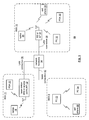
- FIG. 1 is a schematic block diagram of a wireless communication system in accordance with the present invention
- FIG. 2 is a schematic block diagram of an embodiment of a wireless communication device in accordance with the present invention.
- FIG. 3 is a schematic block diagram of an embodiment of an up-conversion module in accordance with the present invention.
- FIG. 4 is a schematic block diagram of an embodiment of a DAC module and an embodiment of a power amplifier module in accordance with the present invention
- FIG. 5 is a schematic block diagram of another embodiment of a wireless communication device in accordance with the present invention.
- FIG. 6 is a schematic block diagram of another embodiment of a DAC module in accordance with the present invention.
- FIG. 7 is a schematic block diagram of an embodiment of a digital to analog converter in accordance with the present invention.
- FIG. 8 is a schematic block diagram of an embodiment of a current to voltage module in accordance with the present invention.
- FIG. 1 is a schematic block diagram illustrating a communication system 10 that includes a plurality of base stations and/or access points 12 , 16 , a plurality of wireless communication devices 18 - 32 and a network hardware component 34 .
- the network hardware 34 which may be a router, switch, bridge, modem, system controller, et cetera provides a wide area network connection 42 for the communication system 10 .
- the wireless communication devices 18 - 32 may be laptop host computers 18 and 26 , personal digital assistant hosts 20 and 30 , personal computer hosts 24 and 32 and/or cellular telephone hosts 22 and 28 . The details of the wireless communication devices will be described in greater detail with reference to FIGS. 2-8 .
- Wireless communication devices 22 , 23 , and 24 are located within an independent basic service set (IBSS) area and communicate directly (i.e., point to point). In this configuration, these devices 22 , 23 , and 24 may only communicate with each other. To communicate with other wireless communication devices within the system 10 or to communicate outside of the system 10 , the devices 22 , 23 , and/or 24 need to affiliate with one of the base stations or access points 12 or 16 .
- IBSS independent basic service set
- the base stations or access points 12 , 16 are located within basic service set (BSS) areas 11 and 13 , respectively, and are operably coupled to the network hardware 34 via local area network connections 36 , 38 . Such a connection provides the base station or access point 12 , 16 with connectivity to other devices within the system 10 and provides connectivity to other networks via the WAN connection 42 .
- BSS basic service set
- each of the base stations or access points 12 - 16 has an associated antenna or antenna array.
- base station or access point 12 wirelessly communicates with wireless communication devices 18 and 20 while base station or access point 16 wirelessly communicates with wireless communication devices 26 - 32 .
- the wireless communication devices register with a particular base station or access point 12 , 16 to receive services from the communication system 10 .
- each wireless communication device includes a built-in radio and/or is coupled to a radio.
- the wireless communication devices may include an RFID reader and/or an RFID tag.
- FIG. 2 is a schematic block diagram of an embodiment of a wireless communication device 18 - 32 that includes a host device 50 and a transceiver 52 .
- the host device 50 may include laptop computer circuitry, personal computer circuitry, PDA circuitry, cellular voice and/or data processing circuitry, personal entertainment circuitry, and/or a processing module.
- the processing module may be a single processing device or a plurality of processing devices.
- Such a processing device may be a microprocessor, micro-controller, digital signal processor, microcomputer, central processing unit, field programmable gate array, programmable logic device, state machine, logic circuitry, analog circuitry, digital circuitry, and/or any device that manipulates signals (analog and/or digital) based on hard coding of the circuitry and/or operational instructions.
- the processing module may include an associated memory and/or memory element, which may be a single memory device, a plurality of memory devices, and/or embedded circuitry of the processing module.
- Such a memory device may be a read-only memory, random access memory, volatile memory, non-volatile memory, static memory, dynamic memory, flash memory, cache memory, and/or any device that stores digital information.
- the transceiver 52 includes a receiver 54 , a transmitter 56 , and a host interface 58 .
- the transmitter 56 includes a 1 st baseband processing module 60 , a 2 nd baseband processing module 62 , an up-conversion module 64 , and a radio frequency (RF) front-end 66 .
- the RF front-end 66 includes a digital to analog conversion (DAC) module 70 and a power amplifier (PA) module 72 .
- the 1 st and 2 nd baseband processing modules 60 and 62 may be separate processing modules or a common processing module. Such a processing module may be a single processing device or a plurality of processing devices.
- Such a processing device may be a microprocessor, micro-controller, digital signal processor, microcomputer, central processing unit, field programmable gate array, programmable logic device, state machine, logic circuitry, analog circuitry, digital circuitry, and/or any device that manipulates signals (analog and/or digital) based on hard coding of the circuitry and/or operational instructions.
- the processing module may have an associated memory and/or memory element, which may be a single memory device, a plurality of memory devices, and/or embedded circuitry of the processing module.
- Such a memory device may be a read-only memory, random access memory, volatile memory, non-volatile memory, static memory, dynamic memory, flash memory, cache memory, and/or any device that stores digital information.
- the processing module implements one or more of its functions via a state machine, analog circuitry, digital circuitry, and/or logic circuitry
- the memory and/or memory element storing the corresponding operational instructions may be embedded within, or external to, the circuitry comprising the state machine, analog circuitry, digital circuitry, and/or logic circuitry.
- the memory element stores, and the processing module executes, hard coded and/or operational instructions corresponding to at least some of the steps and/or functions illustrated in FIGS. 2-8 .
- the receiver 54 which function in accordance with one or more standards (e.g., GSM, EDGE, CDMA, GPRS, etc.), receives inbound RF signals 102 and converts them into inbound data 104 .
- the inbound data 104 is provided to the host device 50 via the host interface 58 .
- the inbound RF signals are in accordance with Gaussian Minimum Shift Keying (GMSK) of a version of the GSM standard, they are phase modulated RF signals.
- GMSK Gaussian Minimum Shift Keying
- the receiver 64 extracts the phase information from the phase modulated RF signals and converts the phase information into the inbound data 104 .
- the inbound RF signals are in accordance with 8-PSK (phase shift keying) of a version of the EDGE standard, they are phase and amplitude modulated RF signals.
- the receiver 64 extracts phase information and modulation information from the phase and amplitude modulated RF signals and converts the phase information and amplitude information into the inbound data 104 .
- the transmitter 56 receives 1 st or 2 nd outbound data 74 or 82 from the host device 50 via the host interface 58 .
- the 1 st outbound data 74 corresponds to data that is to be transmitted in accordance with a wireless communication standard that employs a data modulation scheme having varying amplitudes and varying phases (e.g., 8-PSK of EDGE, quadrature amplitude modulation of IEEE 802.11, etc.)
- the 2 nd outbound data 82 corresponds to data that is be transmitted in accordance with a wireless communication standard that employs a data modulation scheme having varying phases (e.g., GSMK of GSM and GPRS, quadrature-PSK of CDMA, etc.).
- the host device 50 When the host device 50 desires to transmit the 1 st outbound data 74 (e.g., an EDGE data transmission), the host device 50 places the transmitter 56 in a first mode. In the first mode, the 1 st baseband processing module 60 is active to receive the 1 st outbound data 74 .
- the 1 st baseband processing module 60 converts the 1 st outbound data 74 into first symbols 76 that include first phase information 76 and amplitude information 80 .
- the 1 st baseband processing module 60 may encode, puncture, map, interleave, and/or domain convert the 1 st outbound data 74 into polar coordinate symbols of amplitude information 80 (A) and phase information 78 ( ⁇ ).
- a first outbound data value and a second outbound data value may be 1 ⁇ 2 rate encoded to produce 1 st and 2 nd encoded values.
- the encoded values may be interleaved to produce a first interleaved value and a second interleaved value.
- the first interleaved value is mapped into an amplitude value of A 0 and a phase value of ⁇ 0 and the second interleaved value is mapped into an amplitude value of A 1 and a phase value of ⁇ 1 .
- the up-conversion module 64 receives the 1 st phase information 78 and produces therefrom 1 st phase modulated RF signals 90 .
- the DAC module 70 receives the amplitude information 80 and converts it into analog amplitude adjust signals 94 .
- the PA module 72 amplifies the 1 st phase modulate RF signals 90 in accordance with the analog amplitude adjust signals 94 to produce 1 st outbound RF signals 98 .
- the RF front-end 66 and/or the up-conversion module 64 may include synchronization circuitry to insure that the 1 st phase modulated RF signals 90 and the analog amplitude adjust signals 94 correspond, in time, with the 1 st phase information 78 and amplitude information 80 .
- the host device 50 When the host device 50 desires to transmit the 2 nd outbound data 82 (e.g., a GSM voice transmission), the host device 50 places the transmitter 56 in a second mode.
- the 2 nd baseband processing module 62 In the second mode, the 2 nd baseband processing module 62 is active to convert the 2 nd outbound data 82 into 2 nd symbols 84 that include 2 nd phase information 86 and may also generate power level information 88 .
- the 2 nd baseband processing module 62 may encode, puncture, map, interleave, and/or domain convert the 2 nd outbound data 82 into polar coordinate symbols of fixed amplitude (A) and 2 nd phase information 86 ( ⁇ ).
- a first outbound data value and a second outbound data value may be 1 ⁇ 2 rate encoded to produce 1 st and 2 nd encoded values.
- the encoded values may be interleaved to produce a first interleaved value and a second interleaved value.
- the first interleaved value is mapped into a fixed amplitude value of A and a phase value of ⁇ 0 and the second interleaved value is mapped into the amplitude value of A and a phase value of ⁇ 1 .
- the baseband processing module 62 may then generate a power transmission level 88 .
- the up-conversion module 64 converts the 2 nd phase information 86 of the 2 nd symbols 84 into 2 nd phase modulated RF signals 92 .
- the DAC module 70 converts the power level information 88 into analog power level signals 96 .
- the PA module 72 amplifies the 2 nd phase modulated RF signals 92 in accordance with the analog power level signals 96 to produce 2 nd outbound RF signals 100 .
- the 1 st baseband processing module 60 , the 2 nd baseband processing module 62 , the up-conversion module 64 , the digital to analog conversion module 70 , and a power amplifier driver of the power amplifier module 70 are on a die of an integrated circuit and a power amplifier coupled to the power amplifier module 72 is an external component with respect to the integrated circuit.
- the power amplifier module 72 includes power amplifier driver and a power amplifier that are on the same die of an integrated circuit as the 1 st baseband processing module 60 , the 2 nd baseband processing module 62 , the up-conversion module 64 , and the digital to analog conversion module 70 .
- FIG. 3 is a schematic block diagram of an embodiment of an up-conversion module 64 that includes a multiplexer 110 and a phase locked loop (PLL) 112 .
- the PLL 112 includes a forward path 114 and a feedback path 116 .
- the multiplexer 110 provides the 1 st phase information 78 to the feedback path 116 of the PLL 112 .
- the feedback path 116 (which may include a fixed divider module, a fractional-N divider module, and/or a variable divider module) generates a feedback oscillation 120 based on the 1 st phase modulated RF signals 90 , a divider value, and the 1 st phase information 78 .
- the forward path 114 which may include a phase and/or frequency detector, a charge pump, a loop filter, and a voltage controlled oscillator, generates the 1 st phase modulated RF signals 90 from a reference oscillation 118 and the feedback oscillation 120 .
- the multiplexer 110 When the transmitter is in the second mode, the multiplexer 110 provides the 2 nd phase information 86 to the feedback path 116 of the PLL 112 .
- the feedback path 116 generates the feedback oscillation 120 based on the 2 nd phase modulated RF signals 92 , a divider value, and the 2 nd phase information 86 .
- the forward path 114 generates the 2 nd phase modulated RF signals 92 from a reference oscillation 118 and the feedback oscillation 120 .
- FIG. 4 is a schematic block diagram of an embodiment of a DAC module 70 and an embodiment of a power amplifier module 72 .
- the DAC module 70 includes a multiplexer 130 and a digital to analog converter (DAC) 132 .
- the PA module 72 includes a power amplifier driver 134 , a power amplifier 136 , and a demultiplexer 138 .
- the multiplexer 130 which may be a multiplexer, switching network, and/or gating device, outputs the amplitude information 80 when the transmitter 56 is in the first mode and outputs the power level information 88 when the transmitter 56 is in the second mode.
- the digital to analog converter 132 which may be a sigma delta DAC, converts the amplitude information 80 into the analog amplitude adjust signals 94 and to convert the power level information 88 into the analog power level signals 96 .
- the power amplifier driver 134 which may include one or more drivers coupled in parallel and/or in series, is coupled in series with the power amplifier 136 , which may include one or more amplifiers coupled in parallel and/or in series.
- the power amplifier 136 is off-chip with respect to the power amplifier drive 134 and in another embodiment the power amplifier 136 is on the same chip as the power amplifier driver 134 .
- the demultiplexer 138 which may be a demultiplexer, a switching network, and/or gating device, provides the analog amplitude adjust signals 94 to the power amplifier driver 134 .
- the power amplifier driver 134 amplifies the 1 st phase modulated RF signals 90 in accordance with the analog amplitude adjust signals 94 to produce driver amplified first phase modulated RF signals.
- the power amplifier 136 amplifies the driver amplified first phase modulated RF signals in accordance with a power amplifier gain setting, which may be a default setting or programmed by the 1 st baseband processing module 60 , to produce the first outbound RF signals 98 .
- the demultiplexer 138 When the transmitter 56 is in the second mode, the demultiplexer 138 provides the analog power level signals 96 to the power amplifier 136 .
- the power amplifier driver 134 amplifies the second phase modulated RF signals 92 in accordance with a driver gain setting, which may be a default setting or programmed by the 2 nd baseband processing module 62 , to produce driver amplified second phase modulated RF signals.
- the power amplifier 136 amplifies the driver amplified second phase modulated RF signals in accordance with the analog power level signals 96 to produce the 2 nd outbound RF signals 100 .
- FIG. 5 is a schematic block diagram of another embodiment of a wireless communication device 18 - 32 that includes a host device 50 and a transceiver 52 .
- the host device 50 may include laptop computer circuitry, personal computer circuitry, PDA circuitry, cellular voice and/or data processing circuitry, personal entertainment circuitry, and/or a processing module.
- the transceiver 52 includes a receiver 54 , a transmitter 56 , and a host interface 58 .
- the transmitter 56 includes a baseband processing module 140 , an up-conversion module 64 , and a radio frequency (RF) front-end 66 .
- the RF front-end 66 includes a digital to analog conversion (DAC) module 70 and a power amplifier (PA) module 72 .
- the baseband processing modules 140 may be a processing module. Such a processing module may be a single processing device or a plurality of processing devices.
- Such a processing device may be a microprocessor, micro-controller, digital signal processor, microcomputer, central processing unit, field programmable gate array, programmable logic device, state machine, logic circuitry, analog circuitry, digital circuitry, and/or any device that manipulates signals (analog and/or digital) based on hard coding of the circuitry and/or operational instructions.
- the processing module may have an associated memory and/or memory element, which may be a single memory device, a plurality of memory devices, and/or embedded circuitry of the processing module.
- Such a memory device may be a read-only memory, random access memory, volatile memory, non-volatile memory, static memory, dynamic memory, flash memory, cache memory, and/or any device that stores digital information.
- the processing module implements one or more of its functions via a state machine, analog circuitry, digital circuitry, and/or logic circuitry
- the memory and/or memory element storing the corresponding operational instructions may be embedded within, or external to, the circuitry comprising the state machine, analog circuitry, digital circuitry, and/or logic circuitry.
- the memory element stores, and the processing module executes, hard coded and/or operational instructions corresponding to at least some of the steps and/or functions illustrated in FIGS. 2-8 .
- the receiver 54 which function in accordance with one or more standards (e.g., GSM, EDGE, CDMA, GPRS, etc.), receives inbound RF signals 102 and converts them into inbound data 104 .
- the inbound data 104 is provided to the host device 50 via the host interface 58 .
- the inbound RF signals are in accordance with Gaussian Minimum Shift Keying (GMSK) of a version of the GSM standard, they are phase modulated RF signals.
- GMSK Gaussian Minimum Shift Keying
- the receiver 64 extracts the phase information from the phase modulated RF signals and converts the phase information into the inbound data 104 .
- the inbound RF signals are in accordance with 8-PSK (phase shift keying) of a version of the EDGE standard, they are phase and amplitude modulated RF signals.
- the receiver 64 extracts phase information and modulation information from the phase and amplitude modulated RF signals and converts the phase information and amplitude information into the inbound data 104 .
- the transmitter 56 receives outbound data signals 142 or outbound voice signals 144 from the host device 50 via the host interface 58 .
- the outbound data signals 142 correspond to data that is to be transmitted in accordance with a wireless communication standard that employs a data modulation scheme having varying amplitudes and varying phases (e.g., 8-PSK of EDGE, quadrature amplitude modulation of IEEE 802.11, etc.)
- the voice outbound signals 144 correspond to digitized voice signals that are be transmitted in accordance with a wireless communication standard that employs a data modulation scheme having varying phases (e.g., GSMK of GSM, quadrature-PSK of CDMA, etc.).
- the host device 50 When the host device 50 desires to transmit the outbound data signals 142 (e.g., an EDGE data transmission), the host device 50 places the transmitter 56 in a first mode. In the first mode, the baseband processing module 140 receives converts the outbound data signals 142 into data symbols 146 that include first phase information 76 and amplitude information 80 . In one embodiment, the baseband processing module 140 may encode, puncture, map, interleave, and/or domain convert the outbound data signals 142 into polar coordinate symbols of amplitude information 80 (A) and phase information 78 ( ⁇ ).
- A amplitude information 80
- ⁇ phase information 78
- a first outbound data value and a second outbound data value may be 1 ⁇ 2 rate encoded to produce 1 st and 2 nd encoded values.
- the encoded values may be interleaved to produce a first interleaved value and a second interleaved value.
- the first interleaved value is mapped into an amplitude value of A 0 and a phase value of ⁇ 0 and the second interleaved value is mapped into an amplitude value of A 1 and a phase value of ⁇ 1 .
- the up-conversion module 64 receives the 1 st phase information 78 and produces therefrom 1 st phase modulated RF signals 90 .
- the DAC module 70 receives the amplitude information 80 and converts it into analog amplitude adjust signals 94 .
- the PA module 72 amplifies the 1 st phase modulate RF signals 90 in accordance with the analog amplitude adjust signals 94 to produce outbound RF data signals 150 .
- the RF front-end 66 and/or the up-conversion module 64 may include synchronization circuitry to insure that the 1 st phase modulated RF signals 90 and the analog amplitude adjust signals 94 correspond, in time, with the 1 st phase information 78 and amplitude information 80 .
- the host device 50 When the host device 50 desires to transmit the outbound voice signals 144 (e.g., a GSM voice transmission), the host device 50 places the transmitter 56 in a second mode. In the second mode, the baseband processing module 140 converts the outbound data voice signals 144 into voice symbols 148 that include 2 nd phase information 86 and may also generate power level information 88 . In one embodiment, the baseband processing module 140 may encode, puncture, map, interleave, and/or domain convert the outbound voice signals 144 into polar coordinate symbols of fixed amplitude (A) and 2 nd phase information 86 ( ⁇ ).
- A fixed amplitude
- ⁇ 2 nd phase information
- a first outbound data value and a second outbound data value may be 1 ⁇ 2 rate encoded to produce 1 stand 2 nd encoded values.
- the encoded values may be interleaved to produce a first interleaved value and a second interleaved value.
- the first interleaved value is mapped into a fixed amplitude value of A and a phase value of ⁇ 0 and the second interleaved value is mapped into the amplitude value of A and a phase value of ⁇ 1 .
- the baseband processing module 140 may then generate a power transmission level 88 .
- the up-conversion module 64 converts the 2 nd phase information 86 of the 2 nd symbols 84 into 2 nd phase modulated RF signals 92 .
- the DAC module 70 converts the power level information 88 into analog power level signals 96 .
- the PA module 72 amplifies the 2 nd phase modulated RF signals 92 in accordance with the analog power level signals 96 to produce 2 nd outbound RF signals 100 .
- the baseband processing module 140 , the up-conversion module 64 , the digital to analog conversion module 70 , and a power amplifier driver of the power amplifier module 70 are on a die of an integrated circuit and a power amplifier coupled to the power amplifier module 72 is an external component with respect to the integrated circuit.
- the power amplifier module 72 includes power amplifier driver and a power amplifier that are on the same die of an integrated circuit as the baseband processing module 140 , the up-conversion module 64 , and the digital to analog conversion module 70 .
- FIG. 6 is a schematic block diagram of another embodiment of a DAC module 70 that includes a digital to analog converter 150 , a switch module 154 , and a sample-&-hold circuit 152 .
- the digital to analog converter 150 (an embodiment of which will be described in greater detail with reference to FIG. 7 ) receives a digital signal 156 from a multiplexer 166 .
- the multiplexer 166 provides the amplitude information 80 as the digital signal 156 when the transmitter is in the first mode and provides the power level information 88 when the transmitter is in the second mode.
- the digital to analog converter 150 converts the digital signal 156 into an analog signal 158 .
- the analog signal 158 may be the analog amplitude adjust signals 94 and when the transmitter is in the second mode, the analog signal 158 may be the analog power level signals 96 .
- the switching module 154 (which may be a multiplexer, switching network, and/or a gating device) provides the analog signal 158 (e.g., the analog power level signals 96 ) as the output of the DAC module 70 .
- the switching module 154 provides the analog signal 158 (e.g., the analog amplitude adjust signals 94 ) to the sample-&-hold circuit 152 .
- the output of the sample-&-hold circuit 152 provides the output of the DAC module 70 .
- the sample-&-hold circuit 152 is clocked such that the analog amplitude adjust signals 94 are provided to the PA module 72 in synchronization with the 1 st phase modulated RF signals 90 .
- FIG. 7 is a schematic block diagram of an embodiment of a digital to analog converter 150 that includes a sigma delta modulator 170 , a current amplifier section 172 , and a current to voltage module 174 .
- the sigma-delta modulator 170 which may be a second order or greater sigma delta modulator, converts to the digital signal 156 into a sigma-delta modulated signal 176 .
- the current amplifier section 172 which may include a transconductance amplifier, weighted current sources, and a resistive network, converts the sigma-delta modulated signal 176 into an analog current 178 .
- the current to voltage module 174 converts the analog current 178 into the analog signal 158 .
- FIG. 8 is a schematic block diagram of an embodiment of a current to voltage module 174 that includes a variable current source 182 and an impedance 180 .
- the variable current source 182 is varied based on the analog current 178 to produce a reference current, which flows through impedance 180 to establish a voltage representation of the analog signal 158 .
- the impedance includes a variable impedance coupled to produce the analog signal in accordance with a current-to-voltage gain setting (e.g., an impedance setting set by the baseband processing module 140 ).
- the variable current source 182 is coupled to produce a reference current based on the analog current and a current-to-voltage gain setting (e.g., a bias level set by the baseband processing module 140 ).
- the terms “substantially” and “approximately” provides an industry-accepted tolerance for its corresponding term and/or relativity between items. Such an industry-accepted tolerance ranges from less than one percent to fifty percent and corresponds to, but is not limited to, component values, integrated circuit process variations, temperature variations, rise and fall times, and/or thermal noise. Such relativity between items ranges from a difference of a few percent to magnitude differences.
- the term(s) “coupled to” and/or “coupling” and/or includes direct coupling between items and/or indirect coupling between items via an intervening item (e.g., an item includes, but is not limited to, a component, an element, a circuit, and/or a module) where, for indirect coupling, the intervening item does not modify the information of a signal but may adjust its current level, voltage level, and/or power level.
- an intervening item e.g., an item includes, but is not limited to, a component, an element, a circuit, and/or a module
- inferred coupling i.e., where one element is coupled to another element by inference
- the term “operable to” indicates that an item includes one or more of power connections, input(s), output(s), etc., to perform one or more its corresponding functions and may further include inferred coupling to one or more other items.
- the term “associated with”, includes direct and/or indirect coupling of separate items and/or one item being embedded within another item.
- the term “compares favorably”, indicates that a comparison between two or more items, signals, etc., provides a desired relationship. For example, when the desired relationship is that signal 1 has a greater magnitude than signal 2, a favorable comparison may be achieved when the magnitude of signal 1 is greater than that of signal 2 or when the magnitude of signal 2 is less than that of signal 1.
Abstract
Description
Claims (17)
Priority Applications (2)
| Application Number | Priority Date | Filing Date | Title |
|---|---|---|---|
| US11/638,623 US7734258B2 (en) | 2006-12-13 | 2006-12-13 | RF transmitter front-end and applications thereof |
| US12/789,470 US8145146B2 (en) | 2006-12-13 | 2010-05-28 | RF transmitter front-end and applications thereof |
Applications Claiming Priority (1)
| Application Number | Priority Date | Filing Date | Title |
|---|---|---|---|
| US11/638,623 US7734258B2 (en) | 2006-12-13 | 2006-12-13 | RF transmitter front-end and applications thereof |
Related Child Applications (1)
| Application Number | Title | Priority Date | Filing Date |
|---|---|---|---|
| US12/789,470 Continuation US8145146B2 (en) | 2006-12-13 | 2010-05-28 | RF transmitter front-end and applications thereof |
Publications (2)
| Publication Number | Publication Date |
|---|---|
| US20080146173A1 US20080146173A1 (en) | 2008-06-19 |
| US7734258B2 true US7734258B2 (en) | 2010-06-08 |
Family
ID=39527930
Family Applications (2)
| Application Number | Title | Priority Date | Filing Date |
|---|---|---|---|
| US11/638,623 Expired - Fee Related US7734258B2 (en) | 2006-12-13 | 2006-12-13 | RF transmitter front-end and applications thereof |
| US12/789,470 Expired - Fee Related US8145146B2 (en) | 2006-12-13 | 2010-05-28 | RF transmitter front-end and applications thereof |
Family Applications After (1)
| Application Number | Title | Priority Date | Filing Date |
|---|---|---|---|
| US12/789,470 Expired - Fee Related US8145146B2 (en) | 2006-12-13 | 2010-05-28 | RF transmitter front-end and applications thereof |
Country Status (1)
| Country | Link |
|---|---|
| US (2) | US7734258B2 (en) |
Cited By (2)
| Publication number | Priority date | Publication date | Assignee | Title |
|---|---|---|---|---|
| US20080153541A1 (en) * | 2006-12-20 | 2008-06-26 | Broadcom Corporation | Single chip wireless transceiver operable to perform voice, data and radio frequency (rf) processing |
| US20100240328A1 (en) * | 2006-12-13 | 2010-09-23 | Broadcom Corporation | Rf transmitter front-end and applications thereof |
Families Citing this family (5)
| Publication number | Priority date | Publication date | Assignee | Title |
|---|---|---|---|---|
| WO2008141103A1 (en) | 2007-05-10 | 2008-11-20 | Skyworks Solutions, Inc. | Low noise rf driver |
| US20090221232A1 (en) * | 2008-02-29 | 2009-09-03 | Estevez Leonardo W | Portable Telephone With Unitary Transceiver Having Cellular and RFID Functionality |
| KR101740567B1 (en) * | 2012-10-22 | 2017-06-08 | 한국전자통신연구원 | Apparatus and method for transmitting with multiple antenna or multiple bandwidth |
| DE102017124343B4 (en) * | 2016-12-16 | 2021-04-08 | Infineon Technologies Ag | GENERATION OF FAST FREQUENCY Ramps |
| US10292111B1 (en) | 2018-03-14 | 2019-05-14 | Corning Optical Communications LLC | Gain control circuit supporting dynamic gain control in a remote unit in a wireless distribution system (WDS) |
Citations (8)
| Publication number | Priority date | Publication date | Assignee | Title |
|---|---|---|---|---|
| US4381495A (en) | 1979-10-24 | 1983-04-26 | Hitachi, Ltd. | Digital-to-analog converter with error compensation |
| US4471340A (en) | 1981-06-02 | 1984-09-11 | The United States Of America As Represented By The Secretary Of The Navy | Analog to digital converter |
| US4845498A (en) | 1985-07-09 | 1989-07-04 | Teac Corporation | Wide dynamic range digital to analog conversion method and systems |
| US4864305A (en) | 1987-03-13 | 1989-09-05 | Seikosha Co., Ltd. | D/A converter |
| US7183949B2 (en) * | 2004-06-16 | 2007-02-27 | Samsung Electronics Co., Ltd. | Analog baseband processor and method of processing analog baseband for use in multimode communication system |
| US7463696B2 (en) * | 2002-03-04 | 2008-12-09 | Infineon Technologies Ag | Transmission arrangement |
| US7463176B2 (en) * | 2006-12-13 | 2008-12-09 | Broadcom Corporation | DAC module and applications thereof |
| US7564922B2 (en) * | 2005-01-04 | 2009-07-21 | Samsung Electronics Co., Ltd. | RF transmitter for efficiently compensating output power variation due to temperature and process |
Family Cites Families (1)
| Publication number | Priority date | Publication date | Assignee | Title |
|---|---|---|---|---|
| US7734258B2 (en) * | 2006-12-13 | 2010-06-08 | Broadcom Corporation | RF transmitter front-end and applications thereof |
-
2006
- 2006-12-13 US US11/638,623 patent/US7734258B2/en not_active Expired - Fee Related
-
2010
- 2010-05-28 US US12/789,470 patent/US8145146B2/en not_active Expired - Fee Related
Patent Citations (8)
| Publication number | Priority date | Publication date | Assignee | Title |
|---|---|---|---|---|
| US4381495A (en) | 1979-10-24 | 1983-04-26 | Hitachi, Ltd. | Digital-to-analog converter with error compensation |
| US4471340A (en) | 1981-06-02 | 1984-09-11 | The United States Of America As Represented By The Secretary Of The Navy | Analog to digital converter |
| US4845498A (en) | 1985-07-09 | 1989-07-04 | Teac Corporation | Wide dynamic range digital to analog conversion method and systems |
| US4864305A (en) | 1987-03-13 | 1989-09-05 | Seikosha Co., Ltd. | D/A converter |
| US7463696B2 (en) * | 2002-03-04 | 2008-12-09 | Infineon Technologies Ag | Transmission arrangement |
| US7183949B2 (en) * | 2004-06-16 | 2007-02-27 | Samsung Electronics Co., Ltd. | Analog baseband processor and method of processing analog baseband for use in multimode communication system |
| US7564922B2 (en) * | 2005-01-04 | 2009-07-21 | Samsung Electronics Co., Ltd. | RF transmitter for efficiently compensating output power variation due to temperature and process |
| US7463176B2 (en) * | 2006-12-13 | 2008-12-09 | Broadcom Corporation | DAC module and applications thereof |
Cited By (6)
| Publication number | Priority date | Publication date | Assignee | Title |
|---|---|---|---|---|
| US20100240328A1 (en) * | 2006-12-13 | 2010-09-23 | Broadcom Corporation | Rf transmitter front-end and applications thereof |
| US8145146B2 (en) * | 2006-12-13 | 2012-03-27 | Broadcom Corporation | RF transmitter front-end and applications thereof |
| US20080153541A1 (en) * | 2006-12-20 | 2008-06-26 | Broadcom Corporation | Single chip wireless transceiver operable to perform voice, data and radio frequency (rf) processing |
| US7945216B2 (en) * | 2006-12-20 | 2011-05-17 | Broadcom Corporation | Single chip wireless transceiver operable to perform voice, data and radio frequency (RF) processing |
| US20110188553A1 (en) * | 2006-12-20 | 2011-08-04 | Broadcom Corporation | Single chip wireless transceiver operable to perform voice, data and radio frequency (rf) processing |
| US8073397B2 (en) * | 2006-12-20 | 2011-12-06 | Broadcom Corporation | Single chip wireless transceiver operable to perform voice, data and radio frequency (RF) processing |
Also Published As
| Publication number | Publication date |
|---|---|
| US20080146173A1 (en) | 2008-06-19 |
| US20100240328A1 (en) | 2010-09-23 |
| US8145146B2 (en) | 2012-03-27 |
Similar Documents
| Publication | Publication Date | Title |
|---|---|---|
| US8010153B2 (en) | RFIC with cellular and RFID functionality | |
| US7737872B2 (en) | DAC module and applications thereof | |
| US7848725B2 (en) | RF transmitter with stable on-chip PLL | |
| US8145146B2 (en) | RF transmitter front-end and applications thereof | |
| US8749318B2 (en) | Enhanced polar modulator for transmitter | |
| US20040001560A1 (en) | Analog FSK modulator for a radio transmitter | |
| JP4690835B2 (en) | Transmitter and mobile communication terminal using the same | |
| US8320855B2 (en) | Probability optimized power amplifier module and transmitter | |
| US7583941B2 (en) | Apparatus and method to adjust and filter current DAC signals | |
| US8170501B2 (en) | WCDMA transmit architecture | |
| US7570122B2 (en) | Low voltage LOGEN | |
| US7684767B2 (en) | Voice, data and RF integrated circuit with multiple modulation modes and methods for use therewith | |
| US7772936B2 (en) | Polar feedback architecture | |
| US7598813B2 (en) | Radio frequency amplifier with constant gain setting | |
| US7949311B2 (en) | RF integrated circuit with transmitter and multipurpose output ports and methods for use therewith |
Legal Events
| Date | Code | Title | Description |
|---|---|---|---|
| AS | Assignment |
Owner name: BROADCOM CORPORATION, CALIFORNIA Free format text: ASSIGNMENT OF ASSIGNORS INTEREST;ASSIGNORS:NARIMAN, MOHAMMAD;ZOLFAGHARI, ALIREZA;DARABI, HOOMAN;REEL/FRAME:019202/0109 Effective date: 20061212 Owner name: BROADCOM CORPORATION,CALIFORNIA Free format text: ASSIGNMENT OF ASSIGNORS INTEREST;ASSIGNORS:NARIMAN, MOHAMMAD;ZOLFAGHARI, ALIREZA;DARABI, HOOMAN;REEL/FRAME:019202/0109 Effective date: 20061212 |
|
| FEPP | Fee payment procedure |
Free format text: PAYOR NUMBER ASSIGNED (ORIGINAL EVENT CODE: ASPN); ENTITY STATUS OF PATENT OWNER: LARGE ENTITY |
|
| STCF | Information on status: patent grant |
Free format text: PATENTED CASE |
|
| FPAY | Fee payment |
Year of fee payment: 4 |
|
| AS | Assignment |
Owner name: BANK OF AMERICA, N.A., AS COLLATERAL AGENT, NORTH CAROLINA Free format text: PATENT SECURITY AGREEMENT;ASSIGNOR:BROADCOM CORPORATION;REEL/FRAME:037806/0001 Effective date: 20160201 Owner name: BANK OF AMERICA, N.A., AS COLLATERAL AGENT, NORTH Free format text: PATENT SECURITY AGREEMENT;ASSIGNOR:BROADCOM CORPORATION;REEL/FRAME:037806/0001 Effective date: 20160201 |
|
| AS | Assignment |
Owner name: AVAGO TECHNOLOGIES GENERAL IP (SINGAPORE) PTE. LTD., SINGAPORE Free format text: ASSIGNMENT OF ASSIGNORS INTEREST;ASSIGNOR:BROADCOM CORPORATION;REEL/FRAME:041706/0001 Effective date: 20170120 Owner name: AVAGO TECHNOLOGIES GENERAL IP (SINGAPORE) PTE. LTD Free format text: ASSIGNMENT OF ASSIGNORS INTEREST;ASSIGNOR:BROADCOM CORPORATION;REEL/FRAME:041706/0001 Effective date: 20170120 |
|
| AS | Assignment |
Owner name: BROADCOM CORPORATION, CALIFORNIA Free format text: TERMINATION AND RELEASE OF SECURITY INTEREST IN PATENTS;ASSIGNOR:BANK OF AMERICA, N.A., AS COLLATERAL AGENT;REEL/FRAME:041712/0001 Effective date: 20170119 |
|
| MAFP | Maintenance fee payment |
Free format text: PAYMENT OF MAINTENANCE FEE, 8TH YEAR, LARGE ENTITY (ORIGINAL EVENT CODE: M1552) Year of fee payment: 8 |
|
| AS | Assignment |
Owner name: AVAGO TECHNOLOGIES INTERNATIONAL SALES PTE. LIMITE Free format text: MERGER;ASSIGNOR:AVAGO TECHNOLOGIES GENERAL IP (SINGAPORE) PTE. LTD.;REEL/FRAME:047196/0687 Effective date: 20180509 |
|
| AS | Assignment |
Owner name: AVAGO TECHNOLOGIES INTERNATIONAL SALES PTE. LIMITE Free format text: CORRECTIVE ASSIGNMENT TO CORRECT THE EFFECTIVE DATE OF MERGER TO 9/5/2018 PREVIOUSLY RECORDED AT REEL: 047196 FRAME: 0687. ASSIGNOR(S) HEREBY CONFIRMS THE MERGER;ASSIGNOR:AVAGO TECHNOLOGIES GENERAL IP (SINGAPORE) PTE. LTD.;REEL/FRAME:047630/0344 Effective date: 20180905 |
|
| AS | Assignment |
Owner name: AVAGO TECHNOLOGIES INTERNATIONAL SALES PTE. LIMITE Free format text: CORRECTIVE ASSIGNMENT TO CORRECT THE PROPERTY NUMBERS PREVIOUSLY RECORDED AT REEL: 47630 FRAME: 344. ASSIGNOR(S) HEREBY CONFIRMS THE ASSIGNMENT;ASSIGNOR:AVAGO TECHNOLOGIES GENERAL IP (SINGAPORE) PTE. LTD.;REEL/FRAME:048883/0267 Effective date: 20180905 |
|
| FEPP | Fee payment procedure |
Free format text: MAINTENANCE FEE REMINDER MAILED (ORIGINAL EVENT CODE: REM.); ENTITY STATUS OF PATENT OWNER: LARGE ENTITY |
|
| LAPS | Lapse for failure to pay maintenance fees |
Free format text: PATENT EXPIRED FOR FAILURE TO PAY MAINTENANCE FEES (ORIGINAL EVENT CODE: EXP.); ENTITY STATUS OF PATENT OWNER: LARGE ENTITY |
|
| STCH | Information on status: patent discontinuation |
Free format text: PATENT EXPIRED DUE TO NONPAYMENT OF MAINTENANCE FEES UNDER 37 CFR 1.362 |
|
| FP | Lapsed due to failure to pay maintenance fee |
Effective date: 20220608 |