US7729368B2 - Network buffer caching - Google Patents
Network buffer caching Download PDFInfo
- Publication number
- US7729368B2 US7729368B2 US11/655,581 US65558107A US7729368B2 US 7729368 B2 US7729368 B2 US 7729368B2 US 65558107 A US65558107 A US 65558107A US 7729368 B2 US7729368 B2 US 7729368B2
- Authority
- US
- United States
- Prior art keywords
- network
- network buffer
- buffer
- data
- packet
- Prior art date
- Legal status (The legal status is an assumption and is not a legal conclusion. Google has not performed a legal analysis and makes no representation as to the accuracy of the status listed.)
- Active, expires
Links
Images


Classifications
-
- H—ELECTRICITY
- H04—ELECTRIC COMMUNICATION TECHNIQUE
- H04L—TRANSMISSION OF DIGITAL INFORMATION, e.g. TELEGRAPHIC COMMUNICATION
- H04L69/00—Network arrangements, protocols or services independent of the application payload and not provided for in the other groups of this subclass
- H04L69/16—Implementation or adaptation of Internet protocol [IP], of transmission control protocol [TCP] or of user datagram protocol [UDP]
-
- H—ELECTRICITY
- H04—ELECTRIC COMMUNICATION TECHNIQUE
- H04L—TRANSMISSION OF DIGITAL INFORMATION, e.g. TELEGRAPHIC COMMUNICATION
- H04L49/00—Packet switching elements
- H04L49/90—Buffering arrangements
-
- H—ELECTRICITY
- H04—ELECTRIC COMMUNICATION TECHNIQUE
- H04L—TRANSMISSION OF DIGITAL INFORMATION, e.g. TELEGRAPHIC COMMUNICATION
- H04L49/00—Packet switching elements
- H04L49/90—Buffering arrangements
- H04L49/901—Buffering arrangements using storage descriptor, e.g. read or write pointers
-
- H—ELECTRICITY
- H04—ELECTRIC COMMUNICATION TECHNIQUE
- H04L—TRANSMISSION OF DIGITAL INFORMATION, e.g. TELEGRAPHIC COMMUNICATION
- H04L69/00—Network arrangements, protocols or services independent of the application payload and not provided for in the other groups of this subclass
- H04L69/16—Implementation or adaptation of Internet protocol [IP], of transmission control protocol [TCP] or of user datagram protocol [UDP]
- H04L69/161—Implementation details of TCP/IP or UDP/IP stack architecture; Specification of modified or new header fields
Definitions
- the present application relates generally to computer systems and data networking.
- Packets of data are transmitted over a network communication system between a server and client devices. These packets are received by a network interface and processed by the network stack at the server.
- the operational performance of the network stack is largely determined by the performance of network interface's hardware circuitry and software code.
- One embodiment relates to a method of processing packets by a network stack.
- a first data packet is received from a client via a network, and a network buffer is allocated for the data packet.
- An indication is given that the data packet is ready for reading by an application.
- the network buffer is cached in a network buffer cache.
- response data may be received from the application, and the network buffer may be re-used from the network buffer cache.
- the response data may be sent in a second data packet to the client via the network.
- the network buffer may be freed.
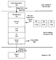
- FIG. 1 is a schematic diagram depicting select components of a network stack of a server.
- FIG. 2 is a schematic diagram depicting the conventional processing of a data packet received from a client by the network interface.
- FIG. 3 is a schematic diagram depicting the conventional processing of data received from a user application by the network interface.
- FIG. 4 is a schematic diagram depicting select steps in the processing of a data packet received from a client by the network stack in accordance with an embodiment of the invention.
- FIG. 5 is a schematic diagram depicting select steps in the processing of reply data received from a user application by the network stack in accordance with an embodiment of the invention.
- FIG. 6 is a flow chart summarizing select steps in the processing of a data packet received from a client by the network stack in accordance with an embodiment of the invention.
- FIG. 7 is a flow chart summarizing select steps in the processing of reply data received from a user application by the network stack in accordance with an embodiment of the invention.
- FIG. 8 is a schematic diagram depicting select steps in the processing of data received from a user application by the network stack in accordance with an alternate embodiment of the invention.
- FIG. 9 is a schematic diagram depicting select steps in the processing of a reply packet received from a client by the network stack in accordance with an alternate embodiment of the invention.
- Applicant has discovered a problematic source of substantial inefficiency in at least some conventional network interfaces. Applicant has further found a solution to this problem which results in substantial performance improvement. The solution advantageously improves performance of transaction-based network applications, with minimal or negligible impact on bulk data transfers.
- FIG. 1 is a schematic diagram depicting select components of a network interface of a server.
- a client computer 104 is shown as communicatively coupled to the server by way of a network 102 .
- the server connects to the network 102 by way of a network interface.
- the diagram divides various software-implemented components of the server into kernel space 106 and user space 108 .
- Software components which manage the server system's resources and the communication between hardware and software components are generally run in kernel space 106
- user applications are generally run in user space 108 .
- a TCP/IP stack 110 is depicted in kernel space 106 .
- the TCP/IP stack 110 includes a device driver 112 , an internet protocol (IP) layer 114 , a transmission control protocol (TCP) layer 116 , a socket layer 118 , and an operating system (OS) interface 120 .
- IP internet protocol
- TCP transmission control protocol
- OS operating system
- a user application 122 is shown in the user space 108 .
- These various components may include processor-readable code which is executable to perform various operations and functions.
- a typical transaction-based application may have multiple clients connected to a single server.
- Each client 104 sends requests to the server, and the server typically responds to each request as quickly as possible.
- the response time witnessed by each client 104 for its request, and the number of simultaneous requests that may be supported by the server depends, on among other factors, the speed at which the networking subsystem processes the incoming and outgoing packets.
- FIG. 2 is a schematic diagram depicting the conventional processing of a data packet received from a client by the network interface. In other words, FIG. 2 shows processing steps in the inbound (receive) path.
- a data packet from a client 104 in the network 102 arrives 202 at the network interface.
- the data packet is received by the driver 112 for the network interface and deposited in the system memory.
- the stack 110 it conceptually moves up in the stack 110 from the driver 112 , to the IP layer 114 , to the TCP layer 116 , to the socket layer 118 , to the OS interface 120 .
- a network buffer is allocated 204 by the networking subsystem to copy the packet for further network processing. As shown, the buffer allocation 204 in the incoming path is typically performed by the driver layer 112 . Thereafter, the packet in the buffer is further processed by the networking subsystem, and the user application is then given an indication that the packet is ready for it to read. The user application then reads 206 the data in the packet.
- the network subsystem frees 208 the allocated buffer. As shown, the freeing 208 of the buffer is typically performed by the socket layer 118 . After being freed, the buffer memory is available to be re-allocated for processing other incoming or outgoing data.
- the user application 112 may satisfy the request by sending the requested data.
- the data is accepted by the network subsystem and is processed as described below.
- FIG. 3 is a schematic diagram depicting select steps in the conventional processing of data received from a user application by the network interface. In other words, FIG. 3 shows processing steps in the outbound (send) path.
- user data from an application 122 in user space 108 of the server is received 302 at the top of the stack 110 by the OS interface 120 .
- the user data is processed by the stack 110 , it conceptually moves down in the stack from the OS interface 120 , to the socket layer 118 , to the TCP layer 116 , to the IP layer 114 , and to the driver 112 .
- a network buffer is allocated 304 by the networking subsystem to copy the user data for further network processing.
- the buffer allocation 304 in the outgoing path is typically performed by the socket layer 118 .
- the user data in the buffer is further processed by the networking subsystem and is then sent 306 to the driver 112 of the network interface for transfer in a data packet via the network 102 to the client 104 .
- the network subsystem frees 308 the allocated buffer. As shown, the freeing 308 of the buffer in the outgoing path is typically performed by the Driver layer 112 . After being freed, the buffer memory is available to be re-allocated for processing other incoming or outgoing data.
- the inefficiency identified herein pertains to the allocation and freeing of the network buffers. Conventionally, it makes sense that, at the end of each individual inbound or outbound process, the allocated buffer would be immediately freed to make the buffer available for re-allocation. For example, in the case of bulk data transfers (either inbound or outbound), such immediate freeing of network buffers leads to good performance.
- Applicant has found a technique that reduces the frequency of network buffer allocation/freeing operations by up to a half (up to 50%) for transaction-based network traffic.
- the technique takes advantage of the following observations.
- a receive (or send) is followed by a send (or receive) iteratively for the life of a typical network connection.
- a typical transaction i.e. a typical send/receive or receive/send pair
- a typical transaction i.e. a typical send/receive or receive/send pair
- a typical transaction i.e. a typical send/receive or receive/send pair
- the traffic patterns of many applications for example, SAP
- a substantial (up to 50%) reduction in buffer allocation/freeing operations for transaction-based applications may be accomplished by caching of the network buffers by the network subsystem.
- caching in the network subsystem is different from caching performed in the memory subsystem.
- the caching of the network buffers may be implemented such that the performance for network-based traffic is improved without significantly affecting the performance for bulk data transfers.
- FIG. 4 is a schematic diagram depicting select steps in the processing of a data packet received from a client by the network stack in accordance with an embodiment of the invention.
- FIG. 4 shows processing steps in the inbound (receive) path, wherein caching of network buffers is utilized to improve transaction-related performance.
- a data packet from a client 104 in the network 102 arrives 402 at the network interface.
- the data packet is received by the driver 112 for the network interface and deposited in the system memory.
- the stack 110 it conceptually moves up in the stack 110 from the driver 112 , to the IP layer 114 , to the TCP layer 116 , to the socket layer 118 , to the OS interface 120 .
- a network buffer is allocated 404 by the networking subsystem to copy the packet for further network processing. As shown, the buffer allocation 404 in the incoming path may be performed by the driver layer 112 . Thereafter, the packet in the buffer is further processed by the networking subsystem, and the user application is then given an indication that the packet is ready for it to read. The user application then reads 406 the data in the packet.
- each memory buffer 410 in the cache is tagged or otherwise associated with a unique (or highly likely to be unique) transaction identifier (ID).
- ID unique (or highly likely to be unique) transaction identifier
- the network buffer cache may be configured so as to be able to hold a limited number of network buffers, where each network buffer may be sized to be able to hold a typical data packet (sized at 1024 bytes, for example).
- the network buffer cache may be configured to hold a maximum of 4, 8, 16, 32, or 64 network buffers. As the maximum number of buffers in the cache increases, the number of transactions which may be efficiently processed at a same time for a user application increases.
- the network buffer cache if the network buffer cache is full when a network buffer is supposed to be cached 408 , then that network buffer is freed, rather than cached.
- This feature advantageously prevents the network buffer cache from significantly affecting bulk data transfers. For example, an inbound bulk data transfer would result in the network buffer cache filling up with the first several packets of the data transfer. The remaining transferred packets may then be processed by allocating and then freeing (for re-allocation) a small number of network buffers.
- the user application 112 may satisfy the request by sending the requested data.
- the data is accepted by the network subsystem and is processed as described below.
- FIG. 5 is a schematic diagram depicting select steps in the processing of reply data received from a user application by the network stack in accordance with an embodiment of the invention.
- FIG. 5 shows processing steps in the outbound (send) path, wherein previously cached network buffers are re-used to improve transaction-related performance.
- reply data from an application 122 in user space 108 of the server is received 502 at the top of the stack 110 by the OS interface 120 .
- the reply data is in response to a previously received request packet.
- the reply data is processed by the stack 110 , it conceptually moves down in the stack from the OS interface 120 , to the socket layer 118 , to the TCP layer 116 , to the IP layer 114 , and to the driver 112 .
- a previously allocated buffer 410 is re-used 504 from the network buffer cache.
- the particular buffer which is re-used 504 is the buffer that is associated with that particular transaction.
- the buffer allocated 404 for a request is re-used 504 for the corresponding reply.
- the buffer re-use 504 in the outgoing path is typically performed by the socket layer 118 . Thereafter, the packet data in the buffer is further processed by the networking subsystem and is then sent to the driver 112 of the network interface for transfer 506 in a data packet via the network 102 to the client 104 .
- the network subsystem frees 508 the network buffer (which was originally allocated 404 during the inbound path of the request packet). As shown, the freeing 508 of the buffer in the outgoing path is typically performed by the driver layer 112 . After being freed, the buffer memory is available to be re-allocated for processing other incoming or outgoing data.
- a network buffer may be allowed to reside in the network cache for only a limited time period. At the end of the allowed time period, the network buffer may be removed from the network cache. This feature advantageously prevents the network buffer cache from becoming filled with network buffers that are not being re-used within a reasonable amount of time which is determined by the allowed time period.
- FIG. 6 is a flow chart summarizing select steps in the processing of a data packet received from a client by the network stack in accordance with an embodiment of the invention. These steps are discussed above in relation to FIG. 4 .
- FIG. 7 is a flow chart summarizing select steps in the processing of reply data received from a user application by the network stack in accordance with an embodiment of the invention. These steps are discussed above in relation to FIG. 5 .
- One advantageous aspect of the above-described technique is that, while it improves the performance of transaction-based applications (which utilize repeated iterations of request and respond packets), it has merely an insubstantial impact on the performance of inbound and outbound bulk data transfers (where a long sequence of packets is sent in one direction).
- Measurements performed in an actual system with a prototype shows an approximate 50% reduction in CPU utilization by functions which allocate and free network buffers (the “allocb” and “freeb” functions, respectively).
- the service demand which is a measure of time taken to complete one transaction, was reduced by 4.4%.
- the transaction throughput which is a measure of the number of transactions done per second, improved by 0.68%.
- network buffer caching may also be applied to transactions initiated with an outbound request packet, and then completed with an inbound response packet.
- FIG. 8 is a schematic diagram depicting select steps in the processing of a data packet received from a user application by the network stack in accordance with an alternate embodiment of the invention.
- FIG. 8 shows processing steps in the outbound (send) path, wherein caching of network buffers is utilized to improve transaction-related performance.
- data packet from an application 122 in user space 108 of the server is received 802 at the top of the stack 110 by the OS interface 120 .
- the data packet may comprise a packet which requests a response.
- the data packet is processed by the stack 110 , it conceptually moves down in the stack from the OS interface 120 , to the socket layer 118 , to the TCP layer 116 , to the IP layer 114 , and to the driver 112 .
- a network buffer is allocated 804 by the networking subsystem to copy the packet for further network processing. As shown, the buffer allocation 804 in the outgoing path may be performed by the socket layer 118 . Thereafter, the packet data in the buffer is further processed by the networking subsystem and is then sent to the driver 112 of the network interface for transfer 806 in a data packet via the network 102 to the client 104 .
- each memory buffer 810 in the cache is tagged or otherwise associated with a unique (or highly likely to be unique) transaction identifier (ID).
- ID unique (or highly likely to be unique) transaction identifier
- FIG. 8 three network buffers ( 810 a , 810 b , and 810 c ) are shown in FIG. 8 , each network buffer having an associated transaction identifier (ID).
- the network buffer cache may be configured so as to be able to hold a limited number of network buffers, where each network buffer may be sized to be able to hold a typical data packet (sized at 1024 bytes, for example).
- the network buffer cache may be configured to hold a maximum of 4, 8, 16, 32, or 64 network buffers. As the maximum number of buffers in the cache increases, the number of transactions which may be efficiently processed at a same time for a user application increases.
- the network buffer cache if the network buffer cache is full when a network buffer is supposed to be cached 808 , then that network buffer is freed, rather than cached.
- This feature advantageously prevents the network buffer cache from significantly affecting bulk data transfers. For example, an outbound bulk data transfer would result in the network buffer cache filling up with the first several packets of the data transfer. The remaining transferred packets may then be processed by allocating and then freeing (for re-allocation) a small number of network buffers.
- FIG. 9 is a schematic diagram depicting select steps in the processing of a response packet received from a client by the network stack in accordance with an alternate embodiment of the invention.
- FIG. 9 shows processing steps in the inbound (receive) path, wherein previously cached network buffers are re-used to improve transaction-related performance
- a response packet from a client 104 in the network 102 arrives 902 at the network interface.
- the response packet is received by the driver 112 for the network interface and deposited in the system memory.
- the packet As the packet is processed by the stack 110 , it conceptually moves up in the stack 110 from the driver 112 , to the IP layer 114 , to the TCP layer 116 , to the socket layer 118 , to the OS interface 120 .
- a previously allocated buffer 810 is re-used 904 from the network buffer cache.
- the particular buffer which is re-used 904 is the buffer that is associated with that particular transaction.
- the buffer allocated 804 for a request is re-used 904 for the corresponding reply.
- the buffer re-use 904 in the incoming path may be performed by the driver layer 112 . Thereafter, the packet in the buffer is further processed by the networking subsystem, and the user application is then given an indication that the packet is ready for it to read. The user application then reads 906 the data in the packet.
- the network subsystem frees 908 the network buffer (which was originally allocated 804 during the outbound path of the request packet). As shown, the freeing 908 of the buffer in the inbound path may be performed at the socket layer 118 . After being freed, the buffer memory is available to be re-allocated for processing other incoming or outgoing data.
- a network buffer may be allowed to reside in the network cache for only a limited time period. At the end of the allowed time period, the network buffer may be removed from the network cache. This feature advantageously prevents the network buffer cache from becoming filled with network buffers that are not being re-used within a reasonable amount of time which is determined by the allowed time period.
- Applicant has discovered a problematic source of substantial inefficiency in at least some conventional network interfaces. This source of inefficiency relates to the repeated allocation and freeing of network buffers for transaction-based applications. Applicant has further found a solution to this problem which results in substantial performance improvement.
- the solution involves creating a network buffer cache and a procedure to re-use previously allocated network buffers using the cache. The solution advantageously improves performance of transaction-based network applications, with minimal or negligible impact on bulk data transfers.
Abstract
Description
Claims (18)
Priority Applications (1)
| Application Number | Priority Date | Filing Date | Title |
|---|---|---|---|
| US11/655,581 US7729368B2 (en) | 2007-01-19 | 2007-01-19 | Network buffer caching |
Applications Claiming Priority (1)
| Application Number | Priority Date | Filing Date | Title |
|---|---|---|---|
| US11/655,581 US7729368B2 (en) | 2007-01-19 | 2007-01-19 | Network buffer caching |
Publications (2)
| Publication Number | Publication Date |
|---|---|
| US20080175258A1 US20080175258A1 (en) | 2008-07-24 |
| US7729368B2 true US7729368B2 (en) | 2010-06-01 |
Family
ID=39641158
Family Applications (1)
| Application Number | Title | Priority Date | Filing Date |
|---|---|---|---|
| US11/655,581 Active 2028-03-02 US7729368B2 (en) | 2007-01-19 | 2007-01-19 | Network buffer caching |
Country Status (1)
| Country | Link |
|---|---|
| US (1) | US7729368B2 (en) |
Cited By (2)
| Publication number | Priority date | Publication date | Assignee | Title |
|---|---|---|---|---|
| US20080263057A1 (en) * | 2007-04-16 | 2008-10-23 | Mark Thompson | Methods and apparatus for transferring data |
| US11245753B2 (en) * | 2018-08-17 | 2022-02-08 | Fastly, Inc. | User space redirect of packet traffic |
Citations (13)
| Publication number | Priority date | Publication date | Assignee | Title |
|---|---|---|---|---|
| US5717932A (en) | 1994-11-04 | 1998-02-10 | Texas Instruments Incorporated | Data transfer interrupt pacing |
| US5933413A (en) | 1997-01-13 | 1999-08-03 | Advanced Micro Devices, Inc. | Adaptive priority determination for servicing transmit and receive in network controllers |
| US6181705B1 (en) | 1993-12-21 | 2001-01-30 | International Business Machines Corporation | System and method for management a communications buffer |
| US6289390B1 (en) * | 1993-08-18 | 2001-09-11 | Microsoft Corporation | System and method for performing remote requests with an on-line service network |
| US20020038309A1 (en) * | 2000-08-30 | 2002-03-28 | Aria Solutions Inc. | System integration framework |
| US20040032936A1 (en) * | 2002-08-15 | 2004-02-19 | Gerald Horel | Transaction processing |
| US20040039550A1 (en) * | 2000-05-03 | 2004-02-26 | Myers Monty G. | System load testing coordination over a network |
| US6701372B2 (en) | 1997-08-22 | 2004-03-02 | Canon Kabushiki Kaisha | Data communication apparatus and method |
| US6801927B1 (en) * | 1999-09-24 | 2004-10-05 | Akamba Corporation | Network adaptor card with reverse proxy and cache and method implemented therewith |
| US20050080874A1 (en) * | 2003-10-14 | 2005-04-14 | Hitachi, Ltd. | Storage device and system for providing communications buffer reservation function |
| US6952407B2 (en) | 2001-02-22 | 2005-10-04 | Snowshore Networks, Inc. | Minimizing latency with content-based adaptive buffering |
| US6959327B1 (en) | 2000-08-29 | 2005-10-25 | International Business Machines Corporation | System and method for dispatching and scheduling network transmissions with feedback |
| US20070133582A1 (en) * | 2005-12-12 | 2007-06-14 | Banerjee Dwip N | Efficient send socket call handling by a transport layer |
-
2007
- 2007-01-19 US US11/655,581 patent/US7729368B2/en active Active
Patent Citations (13)
| Publication number | Priority date | Publication date | Assignee | Title |
|---|---|---|---|---|
| US6289390B1 (en) * | 1993-08-18 | 2001-09-11 | Microsoft Corporation | System and method for performing remote requests with an on-line service network |
| US6181705B1 (en) | 1993-12-21 | 2001-01-30 | International Business Machines Corporation | System and method for management a communications buffer |
| US5717932A (en) | 1994-11-04 | 1998-02-10 | Texas Instruments Incorporated | Data transfer interrupt pacing |
| US5933413A (en) | 1997-01-13 | 1999-08-03 | Advanced Micro Devices, Inc. | Adaptive priority determination for servicing transmit and receive in network controllers |
| US6701372B2 (en) | 1997-08-22 | 2004-03-02 | Canon Kabushiki Kaisha | Data communication apparatus and method |
| US6801927B1 (en) * | 1999-09-24 | 2004-10-05 | Akamba Corporation | Network adaptor card with reverse proxy and cache and method implemented therewith |
| US20040039550A1 (en) * | 2000-05-03 | 2004-02-26 | Myers Monty G. | System load testing coordination over a network |
| US6959327B1 (en) | 2000-08-29 | 2005-10-25 | International Business Machines Corporation | System and method for dispatching and scheduling network transmissions with feedback |
| US20020038309A1 (en) * | 2000-08-30 | 2002-03-28 | Aria Solutions Inc. | System integration framework |
| US6952407B2 (en) | 2001-02-22 | 2005-10-04 | Snowshore Networks, Inc. | Minimizing latency with content-based adaptive buffering |
| US20040032936A1 (en) * | 2002-08-15 | 2004-02-19 | Gerald Horel | Transaction processing |
| US20050080874A1 (en) * | 2003-10-14 | 2005-04-14 | Hitachi, Ltd. | Storage device and system for providing communications buffer reservation function |
| US20070133582A1 (en) * | 2005-12-12 | 2007-06-14 | Banerjee Dwip N | Efficient send socket call handling by a transport layer |
Cited By (5)
| Publication number | Priority date | Publication date | Assignee | Title |
|---|---|---|---|---|
| US20080263057A1 (en) * | 2007-04-16 | 2008-10-23 | Mark Thompson | Methods and apparatus for transferring data |
| US8019830B2 (en) * | 2007-04-16 | 2011-09-13 | Mark Thompson | Methods and apparatus for acquiring file segments |
| US11245753B2 (en) * | 2018-08-17 | 2022-02-08 | Fastly, Inc. | User space redirect of packet traffic |
| US20220150170A1 (en) * | 2018-08-17 | 2022-05-12 | Fastly, Inc. | User space redirect of packet traffic |
| US11792260B2 (en) * | 2018-08-17 | 2023-10-17 | Fastly, Inc. | User space redirect of packet traffic |
Also Published As
| Publication number | Publication date |
|---|---|
| US20080175258A1 (en) | 2008-07-24 |
Similar Documents
| Publication | Publication Date | Title |
|---|---|---|
| US11647081B2 (en) | Method and system for reducing connections to a database | |
| US20170295264A1 (en) | Network extended tcp splicing | |
| US7561573B2 (en) | Network adaptor, communication system and communication method | |
| US7461160B2 (en) | Obtaining a destination address so that a network interface device can write network data without headers directly into host memory | |
| US8392565B2 (en) | Network memory pools for packet destinations and virtual machines | |
| US7370174B2 (en) | Method, system, and program for addressing pages of memory by an I/O device | |
| US8095675B2 (en) | Priority and bandwidth specification at mount time of NAS device volume | |
| EP0889622B1 (en) | Apparatus and method for remote buffer allocation and management for message passing between network nodes | |
| US7822053B2 (en) | Apparatus and method for TCP buffer copy distributed parallel processing | |
| US7499463B1 (en) | Method and apparatus for enforcing bandwidth utilization of a virtual serialization queue | |
| US20080183838A1 (en) | Method, system and computer program product for delivering data to a storage buffer assigned to an application | |
| US20070124378A1 (en) | Method and system for indicate and post processing in a flow through data architecture | |
| EP1528478A1 (en) | Generalized addressing scheme for remote direct memory access enabled devices | |
| JP2005539305A (en) | Network interfaces and protocols | |
| US9225807B2 (en) | Driver level segmentation | |
| CN107302499B (en) | NFV protocol message transmitting and receiving method without copying message buffer | |
| US20220244861A1 (en) | Data Access Method and Apparatus, and First Computing Device | |
| US20110280243A1 (en) | TCP/IP Offload Device | |
| CN108989420A (en) | The method and system of registration service, the method and system for calling service | |
| US9239796B2 (en) | Methods, systems, and computer readable media for caching and using scatter list metadata to control direct memory access (DMA) receiving of network protocol data | |
| US20060167922A1 (en) | Method and apparatus for managing data object size in a multi-user environment | |
| US7729368B2 (en) | Network buffer caching | |
| CN107483637B (en) | NFS-based client link management method and device | |
| US20030236929A1 (en) | Buffer management methods and apparatus for network device drivers | |
| CN112019450A (en) | Inter-device streaming communication |
Legal Events
| Date | Code | Title | Description |
|---|---|---|---|
| AS | Assignment |
Owner name: HEWLETT-PACKARD DEVELOPMENT COMPANY, L.P., TEXAS Free format text: ASSIGNMENT OF ASSIGNORS INTEREST;ASSIGNOR:SAHA, RAKESH;REEL/FRAME:018810/0985 Effective date: 20070118 Owner name: HEWLETT-PACKARD DEVELOPMENT COMPANY, L.P.,TEXAS Free format text: ASSIGNMENT OF ASSIGNORS INTEREST;ASSIGNOR:SAHA, RAKESH;REEL/FRAME:018810/0985 Effective date: 20070118 |
|
| STCF | Information on status: patent grant |
Free format text: PATENTED CASE |
|
| CC | Certificate of correction | ||
| FPAY | Fee payment |
Year of fee payment: 4 |
|
| AS | Assignment |
Owner name: HEWLETT PACKARD ENTERPRISE DEVELOPMENT LP, TEXAS Free format text: ASSIGNMENT OF ASSIGNORS INTEREST;ASSIGNOR:HEWLETT-PACKARD DEVELOPMENT COMPANY, L.P.;REEL/FRAME:037079/0001 Effective date: 20151027 |
|
| MAFP | Maintenance fee payment |
Free format text: PAYMENT OF MAINTENANCE FEE, 8TH YEAR, LARGE ENTITY (ORIGINAL EVENT CODE: M1552) Year of fee payment: 8 |
|
| AS | Assignment |
Owner name: OT PATENT ESCROW, LLC, ILLINOIS Free format text: PATENT ASSIGNMENT, SECURITY INTEREST, AND LIEN AGREEMENT;ASSIGNORS:HEWLETT PACKARD ENTERPRISE DEVELOPMENT LP;HEWLETT PACKARD ENTERPRISE COMPANY;REEL/FRAME:055269/0001 Effective date: 20210115 |
|
| MAFP | Maintenance fee payment |
Free format text: PAYMENT OF MAINTENANCE FEE, 12TH YEAR, LARGE ENTITY (ORIGINAL EVENT CODE: M1553); ENTITY STATUS OF PATENT OWNER: LARGE ENTITY Year of fee payment: 12 |
|
| AS | Assignment |
Owner name: VALTRUS INNOVATIONS LIMITED, IRELAND Free format text: ASSIGNMENT OF ASSIGNORS INTEREST;ASSIGNOR:OT PATENT ESCROW, LLC;REEL/FRAME:058897/0262 Effective date: 20211102 |