US7727251B2 - Low profile dilator for arteriotomy closure system - Google Patents

Low profile dilator for arteriotomy closure system Download PDF

Info

Publication number
US7727251B2
US7727251B2 US11/739,980 US73998007A US7727251B2 US 7727251 B2 US7727251 B2 US 7727251B2 US 73998007 A US73998007 A US 73998007A US 7727251 B2 US7727251 B2 US 7727251B2
Authority
US
United States
Prior art keywords
dilator
lumen
guidewire
distal
proximal
Prior art date
Legal status (The legal status is an assumption and is not a legal conclusion. Google has not performed a legal analysis and makes no representation as to the accuracy of the status listed.)
Expired - Fee Related, expires
Application number
US11/739,980
Other versions
US20080269794A1 (en
Inventor
Matthew Spurchise
Juan-Pablo Mas
Jeffrey J. Witts
Current Assignee (The listed assignees may be inaccurate. Google has not performed a legal analysis and makes no representation or warranty as to the accuracy of the list.)
Medtronic Vascular Inc
Original Assignee
Medtronic Vascular Inc
Priority date (The priority date is an assumption and is not a legal conclusion. Google has not performed a legal analysis and makes no representation as to the accuracy of the date listed.)
Filing date
Publication date
Application filed by Medtronic Vascular Inc filed Critical Medtronic Vascular Inc
Priority to US11/739,980 priority Critical patent/US7727251B2/en
Assigned to MEDTRONIC VASCULAR, INC. reassignment MEDTRONIC VASCULAR, INC. ASSIGNMENT OF ASSIGNORS INTEREST (SEE DOCUMENT FOR DETAILS). Assignors: MAS, JUAN-PABLO, SPURCHISE, MATTHEW, WITTS, JAMES J.
Priority to PCT/US2008/055785 priority patent/WO2008134121A1/en
Publication of US20080269794A1 publication Critical patent/US20080269794A1/en
Application granted granted Critical
Publication of US7727251B2 publication Critical patent/US7727251B2/en
Expired - Fee Related legal-status Critical Current
Adjusted expiration legal-status Critical

Links

Images

Classifications

    • AHUMAN NECESSITIES
    • A61MEDICAL OR VETERINARY SCIENCE; HYGIENE
    • A61BDIAGNOSIS; SURGERY; IDENTIFICATION
    • A61B17/00Surgical instruments, devices or methods, e.g. tourniquets
    • A61B17/0057Implements for plugging an opening in the wall of a hollow or tubular organ, e.g. for sealing a vessel puncture or closing a cardiac septal defect
    • A61B2017/00637Implements for plugging an opening in the wall of a hollow or tubular organ, e.g. for sealing a vessel puncture or closing a cardiac septal defect for sealing trocar wounds through abdominal wall
    • AHUMAN NECESSITIES
    • A61MEDICAL OR VETERINARY SCIENCE; HYGIENE
    • A61BDIAGNOSIS; SURGERY; IDENTIFICATION
    • A61B90/00Instruments, implements or accessories specially adapted for surgery or diagnosis and not covered by any of the groups A61B1/00 - A61B50/00, e.g. for luxation treatment or for protecting wound edges
    • A61B90/06Measuring instruments not otherwise provided for
    • A61B2090/062Measuring instruments not otherwise provided for penetration depth

Definitions

  • the invention relates to devices for closing a percutaneous puncture in a blood vessel after an intravascular procedure and, particularly, to improved low profile dilators usable in the system.
  • Various cardiovascular procedures such as angioplasty, stent placement and atherectomy, among others, are performed by inserting into and manipulating within the vasculature, wires and catheters adapted to perform those procedures.
  • Access to the vasculature typically is through the femoral artery and is percutaneous, involving insertion of a needle in the region of the groin to form a track and to puncture and create an arteriotomy in the femoral artery.
  • a guidewire then is advanced through the needle and into the femoral artery.
  • the needle then is removed.
  • An introducer sheath is then advanced over the guidewire.
  • the wire and sheath provide access into the femoral artery, through the arteriotomy, for catheters or other instrumentalities in order to perform the selected procedure.
  • the procedural devices are removed and the arteriotomy must be closed.
  • a number of techniques are known to facilitate closure and healing of the arteriotomy. These include application of pressure at the puncture site for a relatively extended length of time or the use of biological adhesives or plugs adapted to seal the arteriotomy, among others.
  • Also among the techniques for closing the arteriotomy is the use of a staple system such as described in U.S. Pat. Nos. 6,506,210, 6,767,356 and 7,074,232 to Kanner et al., of which the disclosures of the devices and methods are hereby incorporated by reference.
  • the Kanner patents described a system by which the original introducer sheath is removed, leaving the guidewire in place.
  • an assembly that includes a closure sheath and dilator is advanced along the indwelling guidewire to bring the distal end of the closure sheath into proximity to the outer surface of the arteriotomy.
  • the closure sheath also carries an arrangement of display extending, wire-like stabilizers that, together with the dilator, pass through the arteriotomy into the artery.
  • the free ends of the stabilizers extend beyond the distal end of the closure sheath and are retained within pockets formed in the sides of the dilator to prevent the ends from interfering with advancement of the dilator or closure sheath through tissue.
  • the system enables the portions of the stabilizer wires, once disposed within the artery, to be formed into a temporarily enlarged shape that prevents removal of the stabilizer wires through the arteriotomy.
  • the stabilizers and distal end of the closure sheath then are drawn together to grip the tissue about the arteriotomy and thereby secure and fix the position of the distal end of the sheath over and in alignment with the arteriotomy.
  • the dilator and guidewire then are removed through the closure sheath, leaving the sheath in place adjacent the outer surface of the artery with the stabilizers within the artery, holding the sheath in place in readiness to provides direct access to the arteriotomy.
  • An arteriotomy closure device such as a catheter-like stapler, with a staple carried in its distal end, then is inserted into and advanced through the closure sheath to located the staple in proximity to the arteriotomy.
  • the sheath and stabilizer mechanisms orient the staple in registry with and at a fixed distance from the arteriotomy.
  • the stapler When the stapler is actuated, the prongs of the staple expand and advance toward and into the arterial wall and surrounding tissue on opposite sides of the arteriotomy.
  • the stapling mechanism draws the prongs of the staple together to draw the edges of the arteriotomy together into approximation and then releases the staple.
  • the stabilizers are caused to return to a linear shape, enabling their withdrawal. With the staple deployed and having closed the arteriotomy, the stapling mechanism and sheath may be removed, leaving the staple in place.
  • the dilator described in Kanner U.S. Pat. No. 6,767,356 is circular and has four separate lumens, including a guidewire lumen, a blood marking lumen, and a pair of side lumens.
  • the distal ends of the side lumens server as pockets to temporarily receive the distal ends of the stabilizers when the dilator and closure sheath are advanced through tissue.
  • the dilator includes side port openings in it sides, just beyond the distal end of the sheath, through which the distal ends of the stabilizers can be placed within the pockets.
  • a dilator for use in the arteriotomy closure system that omitted the proximal side lumens.
  • the resulting dilator thus could have a lower profile or, alternatively, would enable the dilator or closure sheath to be further modified to include other operating functions and elements.
  • the modified dilator is formed to include two lumens, including a first lumen receptive to a guidewire, and a dual-function second lumen that is employed both as a blood marking lumen and as a pocket region to releasably receive the distal ends of the stabilizers.
  • the second lumen may be considered as having a proximal segment that defines the blood marking lumen and a short distal segment in which side ports are formed to receive the distal ends of the stabilizers.
  • the invention utilizes a single stabilizer pocket adapted to receive, through the side ports, and contain the distal ends of both stabilizers.
  • the proximal and distal segment of the second lumen are aligned axially such that the common stabilizer pocket and blood marking lumen are arranged in tandem.
  • the guidewire lumen may extend from the distal tip of the dilator along the full length of the dilator to the proximal end, the dilator maintaining a uniform outer cross-sectional configuration.
  • the guidewire lumen is relatively short and located at the distal tip of the dilator, with a proximal guidewire port defining the proximal extend of the guidewire lumen.
  • Catheters having such short distal guidewire lumens are typically referred to as “rapid exchange” devices because of their ability to be removed and/or replaced over standard-length guidewires instead of requiring extra-long “exchange” guidewires.
  • FIG. 2 is a fragmented sectional illustration of a portion of the dilator of FIG. 1 as seen along the line 2 - 2 of FIG. 1 ;
  • FIG. 3 is an isometric, somewhat diagrammatic, illustration of one embodiment of a two-lumen dilator in accordance with the invention
  • FIG. 4 is a longitudinal cross-section of the dilator of FIG. 3 as seen along the plane 4 - 4 of FIG. 3 ;
  • FIGS. 5A-5F are sectional illustrations of the dilator of FIG. 4 as seen along the section planes 5 A- 5 F of FIG. 4 ;
  • FIG. 6 is an isometric illustration of another embodiment of a two lumen dilator incorporating a rapid exchange guidewire lumen in accordance with the invention.
  • FIG. 7 is a sectional illustration of the dilator of FIG. 6 as seen along the plane 7 - 7 of FIG. 6 ;
  • FIGS. 8A-8E are sectional illustrations of the dilator of FIGS. 6 and 7 as seen along the planes 8 A- 8 F of FIG. 7 ;
  • FIG. 9 is a diagrammatic illustration of the manner in which the distal ends of the stabilizers are contained in the common pocket of the dilator.
  • FIGS. 1 and 2 illustrate a dilator 10 of the type described in '356 Kanner patent.
  • the dilator is formed from a somewhat flexible biocompatible polymer and is formed with four lumens including a guidewire lumen 12 that extends the full length of the dilator, a blood marking lumen 14 that extends from the proximal end to a blood marking port 16 located proximally of the distal end of the dilator and a pair of laterally spaced lumens 18 , 20 .
  • Each side lumen 18 , 20 communicates with side ports 22 , 24 respectively in a distal segment of dilator 10 .
  • Side ports 22 , 24 may be cut or otherwise formed in the dilator.
  • Each side port is adapted to receive the distal end of a stabilization wire, shown in phantom diagrammatic fashion at 26 , 28 with the distal ends of the stabilization wires being received in separate distal pockets 30 , 32 .
  • the distal pockets 30 , 32 are formed as continuations of the side lumens 18 , 20 .
  • the cross-section of the dilator is circular and is large enough to accommodate all four lumens along substantially the full length of the dilator.
  • FIGS. 3 , 4 and 5 A- 5 F illustrate one embodiment of a modified dilator in accordance with the invention.
  • the dilator has a shaft 40 formed with two lumens including a first lumen 42 adapted to receive a guidewire, illustrated diagrammatically in phantom at 43 , and a dual-function second lumen 44 that serves to define both a blood marking lumen 46 as well as a single, common pocket 48 to received the distal ends of the stabilizers.
  • the guidewire lumen 42 extend the full length of the dilator from an outlet port at the tapered distal end of shaft 40 to the proximal end of shaft 40 .
  • the blood marking lumen 46 includes a port 50 near the distal end of the lumen.
  • the distal end of the blood marking lumen may be formed by a plug or composition inserted into the region 52 to separate the blood marking lumen 46 from the more distal portions of the second lumen 44 .
  • shaft 40 may be formed by joining different extruded or molded shaft segments, as by melt bonding or adhesive bonding, to form the required lumens and cross-sectional shapes and sizes.
  • a transverse opening is formed through the dilator in communication with the common pocket 48 to define a pair of opposed side ports 54 for the stabilizers.
  • the portion of the second lumen 44 extending distally beyond the side ports 54 define the common pocket 48 to receive and contain the distal ends of both stabilizers.
  • FIG. 9 illustrates, diagrammatically, the manner in which the distal ends of the wire-like stabilizers extend into and are contained within the distal common pocket.
  • the stabilizers extend distally from the sheath 56 and along the sides of the dilator, passing through the side ports 54 and into the common pocket 48 distally of the side ports.
  • the distal ends of the stabilizers are contained within the common pocket during advancement of the system to a deployment position.
  • the dilator then is advanced distally to enable the distal ends of the stabilizers to be withdrawn from the pocket and out of the side ports, after which the stabilizers can be actuated to the stabilizing configuration.
  • FIGS. 5A-5F illustrate sections taken along the length of the dilator from which it may be seen that the dilator may be configured to an oval configuration to an oval configuration.
  • the invention enables the dilator to be formed with an oval cross-section that results in reduction in the cross-sectional dimensions and profile as compared to a circular four-lumen dilator.
  • FIGS. 6 , 7 and 8 A- 8 E illustrate another embodiment of the invention in which the two lumen dilator shaft 60 comprises a rapid exchange guidewire lumen 62 .
  • the guidewire lumen 62 extends from the distal outlet port 64 to a proximal guidewire port 66 located distally of the distal end of the stabilizer pocket 48 .
  • a portion of the guidewire, illustrated diagrammatically in phantom at 43 extending proximally from the proximal guidewire port is disposed outside of the dilator.
  • the dilator shaft 60 in this embodiment, from the proximal guidewire port 66 to the proximal end of the dilator may be of further reduced in cross-sectional configuration and may be circular as shown.

Abstract

A low profile, two lumen dilator is provided for an arteriotomy closure system. The dilator includes a first lumen adapted to receive a guidewire and a second lumen having a proximal segment that defines a blood marking lumen and a distal segment that receives the distal ends of stabilizers in a common pocket. The blood marking lumen and pocket are arranged in tandem. The guidewire lumen may extend the full length of the dilator or may be shortened to provide rapid exchange capability.

Description

FIELD OF THE INVENTION
The invention relates to devices for closing a percutaneous puncture in a blood vessel after an intravascular procedure and, particularly, to improved low profile dilators usable in the system.
BACKGROUND
Various cardiovascular procedures, such as angioplasty, stent placement and atherectomy, among others, are performed by inserting into and manipulating within the vasculature, wires and catheters adapted to perform those procedures. Access to the vasculature typically is through the femoral artery and is percutaneous, involving insertion of a needle in the region of the groin to form a track and to puncture and create an arteriotomy in the femoral artery. A guidewire then is advanced through the needle and into the femoral artery. The needle then is removed. An introducer sheath is then advanced over the guidewire. The wire and sheath provide access into the femoral artery, through the arteriotomy, for catheters or other instrumentalities in order to perform the selected procedure.
After the procedure has been completed, the procedural devices are removed and the arteriotomy must be closed. A number of techniques are known to facilitate closure and healing of the arteriotomy. These include application of pressure at the puncture site for a relatively extended length of time or the use of biological adhesives or plugs adapted to seal the arteriotomy, among others. Also among the techniques for closing the arteriotomy is the use of a staple system such as described in U.S. Pat. Nos. 6,506,210, 6,767,356 and 7,074,232 to Kanner et al., of which the disclosures of the devices and methods are hereby incorporated by reference. The Kanner patents described a system by which the original introducer sheath is removed, leaving the guidewire in place. Then, an assembly that includes a closure sheath and dilator is advanced along the indwelling guidewire to bring the distal end of the closure sheath into proximity to the outer surface of the arteriotomy. The closure sheath also carries an arrangement of display extending, wire-like stabilizers that, together with the dilator, pass through the arteriotomy into the artery.
The free ends of the stabilizers extend beyond the distal end of the closure sheath and are retained within pockets formed in the sides of the dilator to prevent the ends from interfering with advancement of the dilator or closure sheath through tissue.
The system enables the portions of the stabilizer wires, once disposed within the artery, to be formed into a temporarily enlarged shape that prevents removal of the stabilizer wires through the arteriotomy. The stabilizers and distal end of the closure sheath then are drawn together to grip the tissue about the arteriotomy and thereby secure and fix the position of the distal end of the sheath over and in alignment with the arteriotomy. The dilator and guidewire then are removed through the closure sheath, leaving the sheath in place adjacent the outer surface of the artery with the stabilizers within the artery, holding the sheath in place in readiness to provides direct access to the arteriotomy.
An arteriotomy closure device, such as a catheter-like stapler, with a staple carried in its distal end, then is inserted into and advanced through the closure sheath to located the staple in proximity to the arteriotomy. As described more fully in the Kanner patents, the sheath and stabilizer mechanisms orient the staple in registry with and at a fixed distance from the arteriotomy. When the stapler is actuated, the prongs of the staple expand and advance toward and into the arterial wall and surrounding tissue on opposite sides of the arteriotomy. The stapling mechanism then draws the prongs of the staple together to draw the edges of the arteriotomy together into approximation and then releases the staple. The stabilizers are caused to return to a linear shape, enabling their withdrawal. With the staple deployed and having closed the arteriotomy, the stapling mechanism and sheath may be removed, leaving the staple in place.
The dilator described in Kanner U.S. Pat. No. 6,767,356 is circular and has four separate lumens, including a guidewire lumen, a blood marking lumen, and a pair of side lumens. The distal ends of the side lumens server as pockets to temporarily receive the distal ends of the stabilizers when the dilator and closure sheath are advanced through tissue. The dilator includes side port openings in it sides, just beyond the distal end of the sheath, through which the distal ends of the stabilizers can be placed within the pockets. The portions of the side lumens proximal of the side ports, although useful in forming the stabilizer pockets, performed no function during operation or use of the system. It would be desirable, therefore, to provide a dilator for use in the arteriotomy closure system that omitted the proximal side lumens. The resulting dilator thus could have a lower profile or, alternatively, would enable the dilator or closure sheath to be further modified to include other operating functions and elements.
SUMMARY OF THE INVENTION
The modified dilator is formed to include two lumens, including a first lumen receptive to a guidewire, and a dual-function second lumen that is employed both as a blood marking lumen and as a pocket region to releasably receive the distal ends of the stabilizers. The second lumen may be considered as having a proximal segment that defines the blood marking lumen and a short distal segment in which side ports are formed to receive the distal ends of the stabilizers. The invention utilizes a single stabilizer pocket adapted to receive, through the side ports, and contain the distal ends of both stabilizers. The proximal and distal segment of the second lumen are aligned axially such that the common stabilizer pocket and blood marking lumen are arranged in tandem.
In one embodiment, the guidewire lumen may extend from the distal tip of the dilator along the full length of the dilator to the proximal end, the dilator maintaining a uniform outer cross-sectional configuration. In another embodiment, the guidewire lumen is relatively short and located at the distal tip of the dilator, with a proximal guidewire port defining the proximal extend of the guidewire lumen. Catheters having such short distal guidewire lumens are typically referred to as “rapid exchange” devices because of their ability to be removed and/or replaced over standard-length guidewires instead of requiring extra-long “exchange” guidewires. This conventional “rapid exchange” language will be used to describe one embodiment throughout the description of the invention, even though the short guidewire lumen feature is not used for exchanging the inventive dilator. The more proximal portions of the rapid exchange embodiment of the dilator contain only the single, second lumen.
DESCRIPTION OF THE DRAWINGS
The invention will be appreciated more fully from the following further description with reference to the accompanying drawings wherein:
    • FIG. 1 is a diagrammatic illustration of a four-lumen dilator used in arteriotomy closure system described in Kanner U.S. Pat. No. 6,767,356;
FIG. 2 is a fragmented sectional illustration of a portion of the dilator of FIG. 1 as seen along the line 2-2 of FIG. 1;
FIG. 3 is an isometric, somewhat diagrammatic, illustration of one embodiment of a two-lumen dilator in accordance with the invention;
FIG. 4 is a longitudinal cross-section of the dilator of FIG. 3 as seen along the plane 4-4 of FIG. 3;
FIGS. 5A-5F are sectional illustrations of the dilator of FIG. 4 as seen along the section planes 5A-5F of FIG. 4;
FIG. 6 is an isometric illustration of another embodiment of a two lumen dilator incorporating a rapid exchange guidewire lumen in accordance with the invention;
FIG. 7 is a sectional illustration of the dilator of FIG. 6 as seen along the plane 7-7 of FIG. 6;
FIGS. 8A-8E are sectional illustrations of the dilator of FIGS. 6 and 7 as seen along the planes 8A-8F of FIG. 7; and
FIG. 9 is a diagrammatic illustration of the manner in which the distal ends of the stabilizers are contained in the common pocket of the dilator.
DESCRIPTION OF THE PREFERRED EMBODIMENT
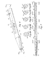
FIGS. 1 and 2 illustrate a dilator 10 of the type described in '356 Kanner patent. The dilator is formed from a somewhat flexible biocompatible polymer and is formed with four lumens including a guidewire lumen 12 that extends the full length of the dilator, a blood marking lumen 14 that extends from the proximal end to a blood marking port 16 located proximally of the distal end of the dilator and a pair of laterally spaced lumens 18, 20. Each side lumen 18, 20 communicates with side ports 22, 24 respectively in a distal segment of dilator 10. Side ports 22, 24 may be cut or otherwise formed in the dilator. Each side port is adapted to receive the distal end of a stabilization wire, shown in phantom diagrammatic fashion at 26, 28 with the distal ends of the stabilization wires being received in separate distal pockets 30, 32. The distal pockets 30, 32 are formed as continuations of the side lumens 18, 20. The cross-section of the dilator is circular and is large enough to accommodate all four lumens along substantially the full length of the dilator.
FIGS. 3, 4 and 5A-5F illustrate one embodiment of a modified dilator in accordance with the invention. The dilator has a shaft 40 formed with two lumens including a first lumen 42 adapted to receive a guidewire, illustrated diagrammatically in phantom at 43, and a dual-function second lumen 44 that serves to define both a blood marking lumen 46 as well as a single, common pocket 48 to received the distal ends of the stabilizers. The guidewire lumen 42 extend the full length of the dilator from an outlet port at the tapered distal end of shaft 40 to the proximal end of shaft 40. The blood marking lumen 46 includes a port 50 near the distal end of the lumen. The distal end of the blood marking lumen may be formed by a plug or composition inserted into the region 52 to separate the blood marking lumen 46 from the more distal portions of the second lumen 44. Alternatively, shaft 40 may be formed by joining different extruded or molded shaft segments, as by melt bonding or adhesive bonding, to form the required lumens and cross-sectional shapes and sizes. A transverse opening is formed through the dilator in communication with the common pocket 48 to define a pair of opposed side ports 54 for the stabilizers. The portion of the second lumen 44 extending distally beyond the side ports 54 define the common pocket 48 to receive and contain the distal ends of both stabilizers.
FIG. 9 illustrates, diagrammatically, the manner in which the distal ends of the wire-like stabilizers extend into and are contained within the distal common pocket. The stabilizers extend distally from the sheath 56 and along the sides of the dilator, passing through the side ports 54 and into the common pocket 48 distally of the side ports. The distal ends of the stabilizers are contained within the common pocket during advancement of the system to a deployment position. As described in further detail in the Kanner '356 patent, the dilator then is advanced distally to enable the distal ends of the stabilizers to be withdrawn from the pocket and out of the side ports, after which the stabilizers can be actuated to the stabilizing configuration.
FIGS. 5A-5F illustrate sections taken along the length of the dilator from which it may be seen that the dilator may be configured to an oval configuration to an oval configuration. The invention enables the dilator to be formed with an oval cross-section that results in reduction in the cross-sectional dimensions and profile as compared to a circular four-lumen dilator.
FIGS. 6, 7 and 8A-8E illustrate another embodiment of the invention in which the two lumen dilator shaft 60 comprises a rapid exchange guidewire lumen 62. In this embodiment, the guidewire lumen 62 extends from the distal outlet port 64 to a proximal guidewire port 66 located distally of the distal end of the stabilizer pocket 48. With this arrangement, a portion of the guidewire, illustrated diagrammatically in phantom at 43 extending proximally from the proximal guidewire port is disposed outside of the dilator. The dilator shaft 60 in this embodiment, from the proximal guidewire port 66 to the proximal end of the dilator may be of further reduced in cross-sectional configuration and may be circular as shown.
It should be understood that the foregoing description of the invention is intended merely to be illustrative thereof and that other embodiments, modifications and equivalents may be apparent to those skilled in the art while remaining within the scope of the invention.

Claims (4)

1. In a wire-guided arteriotomy closure system having a sheath and stabilizers extending distally from the sheath, a low profile dilator for placing the sheath and stabilizers with respect to an arteriotomy comprising:
an elongate dilator shaft having a tapered distal end, the dilator shaft having a first guidewire lumen and a second lumen parallel to the first lumen;
the second lumen having a proximal segment defining a blood marking lumen extending from the proximal end of the dilator to a blood marking port at the distal region of the proximal segment of the second lumen;
the second lumen having a distal segment, the dilator shaft having a pair of side ports formed therein and in communication with the distal segment of the second lumen with a portion of the second lumen extending distally beyond the side ports to define a distally extending pocket receptive to the ends of wire-like stabilizers;
the proximal and distal segments of the second lumen being separated by a plug or composition and being arranged in tandem such that the transverse cross-section of the dilator, over substantially all of its length, has not more than two lumens.
2. A low profile dilator as defined in claim 1 wherein the first guidewire lumen extends the full length of the dilator.
3. A low profile dilator as defined in claim 1 wherein the guidewire lumen extends from a distal guidewire port to a proximal guidewire port, the proximal guidewire port being located distally of the pocket and enabling the dilator to be operated as a rapid exchange device.
4. A low profile dilator as defined in claim 1 wherein the transverse cross-section of the dilator, over substantially all of its length, is oval.
US11/739,980 2007-04-25 2007-04-25 Low profile dilator for arteriotomy closure system Expired - Fee Related US7727251B2 (en)

Priority Applications (2)

Application Number Priority Date Filing Date Title
US11/739,980 US7727251B2 (en) 2007-04-25 2007-04-25 Low profile dilator for arteriotomy closure system
PCT/US2008/055785 WO2008134121A1 (en) 2007-04-25 2008-03-04 Low profile dilator for arteriotomy closure system

Applications Claiming Priority (1)

Application Number Priority Date Filing Date Title
US11/739,980 US7727251B2 (en) 2007-04-25 2007-04-25 Low profile dilator for arteriotomy closure system

Publications (2)

Publication Number Publication Date
US20080269794A1 US20080269794A1 (en) 2008-10-30
US7727251B2 true US7727251B2 (en) 2010-06-01

Family

ID=39560861

Family Applications (1)

Application Number Title Priority Date Filing Date
US11/739,980 Expired - Fee Related US7727251B2 (en) 2007-04-25 2007-04-25 Low profile dilator for arteriotomy closure system

Country Status (2)

Country Link
US (1) US7727251B2 (en)
WO (1) WO2008134121A1 (en)

Cited By (7)

* Cited by examiner, † Cited by third party
Publication number Priority date Publication date Assignee Title
WO2015031252A1 (en) * 2013-08-26 2015-03-05 Merit Medical Systems, Inc. Sheathless guide, rapid exchange dilator and associated methods
US9119935B2 (en) 2012-01-12 2015-09-01 Fischell Innovations, Llc Carotid sheath with entry and tracking rapid exchange dilators and method of use
US9808598B2 (en) 2015-02-04 2017-11-07 Teleflex Medical Incorporated Flexible tip dilator
US10231721B2 (en) 2010-06-24 2019-03-19 St. Croix Surgical Systems, Llc Failsafe percutaneous wound barrier
US10967152B2 (en) 2017-03-10 2021-04-06 Abiomed, Inc. Expandable introducer sheath for medical device
US11660434B2 (en) 2020-02-03 2023-05-30 Abiomed, Inc. Expandable sheath with interlock dilator
US11969563B2 (en) 2023-05-25 2024-04-30 Abiomed, Inc. Expandable introducer sheath for medical device

Families Citing this family (2)

* Cited by examiner, † Cited by third party
Publication number Priority date Publication date Assignee Title
EP3057646B1 (en) * 2013-10-15 2019-03-13 The United States Of America,As Represented By The Secretary, Department Of Health And Human Services Vascular dilators
US11612505B2 (en) * 2020-04-30 2023-03-28 Medtronic Vascular, Inc. Stent graft delivery system with offset tapered tip

Citations (7)

* Cited by examiner, † Cited by third party
Publication number Priority date Publication date Assignee Title
US20010044594A1 (en) * 1987-12-22 2001-11-22 Vas-Cath Incorporated Multiple lumen catheter
US6506210B1 (en) 2000-09-01 2003-01-14 Angiolink Corporation Wound site management and wound closure device
US6641592B1 (en) 1999-11-19 2003-11-04 Lsi Solutions, Inc. System for wound closure
US6767356B2 (en) * 2000-09-01 2004-07-27 Angiolink Corporation Advanced wound site management systems and methods
US7074232B2 (en) 2000-09-01 2006-07-11 Medtronic Angiolink, Inc. Advanced wound site management systems and methods
US20070078478A1 (en) * 2005-07-27 2007-04-05 Atkins Joseph R Catheter and tunneling device therefor
US20070185521A1 (en) * 2005-12-05 2007-08-09 Cook Incorporated Rapid exchange assembly

Family Cites Families (1)

* Cited by examiner, † Cited by third party
Publication number Priority date Publication date Assignee Title
US5489271A (en) * 1994-03-29 1996-02-06 Boston Scientific Corporation Convertible catheter

Patent Citations (7)

* Cited by examiner, † Cited by third party
Publication number Priority date Publication date Assignee Title
US20010044594A1 (en) * 1987-12-22 2001-11-22 Vas-Cath Incorporated Multiple lumen catheter
US6641592B1 (en) 1999-11-19 2003-11-04 Lsi Solutions, Inc. System for wound closure
US6506210B1 (en) 2000-09-01 2003-01-14 Angiolink Corporation Wound site management and wound closure device
US6767356B2 (en) * 2000-09-01 2004-07-27 Angiolink Corporation Advanced wound site management systems and methods
US7074232B2 (en) 2000-09-01 2006-07-11 Medtronic Angiolink, Inc. Advanced wound site management systems and methods
US20070078478A1 (en) * 2005-07-27 2007-04-05 Atkins Joseph R Catheter and tunneling device therefor
US20070185521A1 (en) * 2005-12-05 2007-08-09 Cook Incorporated Rapid exchange assembly

Cited By (12)

* Cited by examiner, † Cited by third party
Publication number Priority date Publication date Assignee Title
US10231721B2 (en) 2010-06-24 2019-03-19 St. Croix Surgical Systems, Llc Failsafe percutaneous wound barrier
US10973503B2 (en) 2010-06-24 2021-04-13 St. Croix Surgical Systems, Llc Failsafe percutaneous wound barrier
US9119935B2 (en) 2012-01-12 2015-09-01 Fischell Innovations, Llc Carotid sheath with entry and tracking rapid exchange dilators and method of use
US9302083B2 (en) 2012-01-12 2016-04-05 Fischell Innovations, Llc Carotid sheath with entry and tracking rapid exchange dilators and method of use
WO2015031252A1 (en) * 2013-08-26 2015-03-05 Merit Medical Systems, Inc. Sheathless guide, rapid exchange dilator and associated methods
US10471241B2 (en) 2013-08-26 2019-11-12 Merit Medical Systems, Inc. Sheathless guide, rapid exchange dilator and associated methods
US9808598B2 (en) 2015-02-04 2017-11-07 Teleflex Medical Incorporated Flexible tip dilator
US10967152B2 (en) 2017-03-10 2021-04-06 Abiomed, Inc. Expandable introducer sheath for medical device
US11697002B2 (en) 2017-03-10 2023-07-11 Abiomed, Inc. Expandable introducer sheath for medical device
US11660434B2 (en) 2020-02-03 2023-05-30 Abiomed, Inc. Expandable sheath with interlock dilator
US11944770B2 (en) 2020-02-03 2024-04-02 Abiomed, Inc. Expandable sheath with interlock dilator
US11969563B2 (en) 2023-05-25 2024-04-30 Abiomed, Inc. Expandable introducer sheath for medical device

Also Published As

Publication number Publication date
US20080269794A1 (en) 2008-10-30
WO2008134121A1 (en) 2008-11-06

Similar Documents

Publication Publication Date Title
US7727251B2 (en) Low profile dilator for arteriotomy closure system
CN215916117U (en) Quick-insertion central catheter assembly
US5328480A (en) Vascular wire guiode introducer and method of use
US6273871B1 (en) Catheter introducer
US6001109A (en) Device and method for suturing blood vessels
US7534223B2 (en) Catheter with formed guide wire ramp
AU2008256823B2 (en) Medical devices, systems and methods for closing perforations
US5876411A (en) Device and method for locating and sealing a blood vessel
US6077279A (en) Device and method employing adhesive for sealing blood vessels and the like
JP4493499B2 (en) Guide wire lock device
EP0788769A1 (en) Suture delivery tool
US20060015130A1 (en) Catheter tunneler adapter
US20120277731A1 (en) Catheter Incorporating a Guidewire Exit Ramp
US8167842B2 (en) Introducer apparatus with cutting edges
EP2227153B1 (en) Two-part extraction balloon
US8419762B2 (en) Split sheath for trocar assembly
JP2014511237A (en) Catheter guide wire introduction device
US20050283193A1 (en) Introducer guide
CN114146290A (en) Wire locking assembly
US20190069886A1 (en) Accessory device for eus-fna needle for guidewire passage
CA3056025A1 (en) Systems and methods for device exchange in an endoscopic procedure
GB2425483A (en) A single step trocar based insertion device
CN111479526B (en) Thin cannula trocar and method
US20080269800A1 (en) Arteriotomy closure system with dual lumens sheath
KR102593656B1 (en) Medical catheter

Legal Events

Date Code Title Description
AS Assignment

Owner name: MEDTRONIC VASCULAR, INC., CALIFORNIA

Free format text: ASSIGNMENT OF ASSIGNORS INTEREST;ASSIGNORS:SPURCHISE, MATTHEW;MAS, JUAN-PABLO;WITTS, JAMES J.;REEL/FRAME:019210/0724

Effective date: 20070425

Owner name: MEDTRONIC VASCULAR, INC.,CALIFORNIA

Free format text: ASSIGNMENT OF ASSIGNORS INTEREST;ASSIGNORS:SPURCHISE, MATTHEW;MAS, JUAN-PABLO;WITTS, JAMES J.;REEL/FRAME:019210/0724

Effective date: 20070425

REMI Maintenance fee reminder mailed
LAPS Lapse for failure to pay maintenance fees
STCH Information on status: patent discontinuation

Free format text: PATENT EXPIRED DUE TO NONPAYMENT OF MAINTENANCE FEES UNDER 37 CFR 1.362

FP Lapsed due to failure to pay maintenance fee

Effective date: 20140601