US7725324B2 - Constrained filter encoding of polyphonic signals - Google Patents
Constrained filter encoding of polyphonic signals Download PDFInfo
- Publication number
- US7725324B2 US7725324B2 US11/011,764 US1176404A US7725324B2 US 7725324 B2 US7725324 B2 US 7725324B2 US 1176404 A US1176404 A US 1176404A US 7725324 B2 US7725324 B2 US 7725324B2
- Authority
- US
- United States
- Prior art keywords
- adaptive filter
- signal
- channel
- constraint
- channel signals
- Prior art date
- Legal status (The legal status is an assumption and is not a legal conclusion. Google has not performed a legal analysis and makes no representation as to the accuracy of the status listed.)
- Active, expires
Links
Images


Classifications
-
- G—PHYSICS
- G10—MUSICAL INSTRUMENTS; ACOUSTICS
- G10L—SPEECH ANALYSIS OR SYNTHESIS; SPEECH RECOGNITION; SPEECH OR VOICE PROCESSING; SPEECH OR AUDIO CODING OR DECODING
- G10L19/00—Speech or audio signals analysis-synthesis techniques for redundancy reduction, e.g. in vocoders; Coding or decoding of speech or audio signals, using source filter models or psychoacoustic analysis
- G10L19/008—Multichannel audio signal coding or decoding using interchannel correlation to reduce redundancy, e.g. joint-stereo, intensity-coding or matrixing
Definitions
- the present invention relates in general to encoding of audio signals, and in particular to encoding of multi-channel audio signals.
- stereophonic or multi-channel coding of audio signals is to encode the signals of the different channels separately as individual and independent signals.
- Another basic way used in stereo FM radio transmission and which ensures compatibility with legacy mono radio receivers is to transmit a sum and a difference signal of the two involved channels.
- M/S stereo coding is similar to the described procedure in stereo FM radio, in a sense that it encodes and transmits the sum and difference signals of the channel sub-bands and thereby exploits redundancy between the channel sub-bands.
- the structure and operation of an encoder based on M/S stereo coding is described, e.g. in U.S. Pat. No. 5,285,498 by J. D. Johnston.
- Intensity stereo on the other hand is able to make use of stereo irrelevancy. It transmits the joint intensity of the channels (of the different sub-bands) along with some location information indicating how the intensity is distributed among the channels. Intensity stereo does only provide spectral magnitude information of the channels. Phase information is not conveyed. For this reason and since the temporal inter-channel information (more specifically the inter-channel time difference) is of major psycho-acoustical relevancy particularly at lower frequencies, intensity stereo can only be used at high frequencies above e.g. 2 kHz.
- An intensity stereo coding method is described, e.g. in the European patent 0497413 by R. Veldhuis et al.
- a recently developed stereo coding method is described, e.g. in a conference paper with the title “Binaural cue coding applied to stereo and multi-channel audio compression”, 112th AES convention, May 2002, Kunststoff, Germany by C. Faller et al.
- This method is a parametric multi-channel audio coding method.
- the basic principle is that at the encoding side, the input signals from N channels c 1 , c 2 , . . . c N are combined to one mono signal m.
- the mono signal is audio encoded using any conventional monophonic audio codec.
- parameters are derived from the channel signals, which describe the multi-channel image.
- the parameters are encoded and transmitted to the decoder, along with the audio bit stream.
- the decoder first decodes the mono signal m′ and then regenerates the channel signals c 1 ′, c 2 ′, . . . , c N ′, based on the parametric description of the multi-channel image.
- the principle of the Binaural Cue Coding (BCC) method is that it transmits the encoded mono signal and so-called BCC parameters.
- the BCC parameters comprise coded inter-channel level differences and inter-channel time differences for sub-bands of the original multi-channel input signal.
- the decoder regenerates the different channel signals by applying sub-band-wise level and phase adjustments of the mono signal based on the BCC parameters.
- the advantage over e.g. M/S or intensity stereo is that stereo information comprising temporal inter-channel information is transmitted at much lower bit rates.
- a problem with the state-of-the-art multi-channel coding techniques described above is that they require high bit rates in order to provide good quality. Intensity stereo, if applied at low bit rates as low as e.g. only a few kbps suffers from the fact that it does not provide any temporal inter-channel information. As this information is perceptually important for low frequencies below e.g. 2 kHz, it is unable to provide a stereo impression at such low frequencies.
- BCC is able to reproduce the multi-channel image even at low frequencies at low bit rates of e.g. 3 kbps since it also transmits temporal inter-channel information.
- this technique requires computational demanding time-frequency transforms on each of the channels, both at the encoder and the decoder.
- BCC optimizes the mapping in a pure mathematical manner. Characteristic artifacts immanent in the coding method will, however, not disappear.
- side information consists of predictor filters and optionally a residual signal.
- the predictor filters estimated by a least-mean-square algorithm, when applied to the mono signal allow the prediction of the multi-channel audio signals.
- This technique synthesizes the right and left channel signals by filtering sound source signals with so-called head-related filters.
- this technique requires the different sound source signals to be separated and can thus not generally be applied for stereo or multi-channel coding.
- the predictor filters are known to be optimal in the least-mean-square sense, they do not always fully restore the perceptual characteristics of the original multi-channel signals.
- stereo image instability may occur, where the sound jumps randomly between left to right.
- spectral nulls may cause instabilities and lead to a filter whose frequency response at these frequencies is aberrant. This may cause the filter to perform unnecessary amplification in certain regions and lead to very annoying audible artifacts, especially if the signals are low-pass or high-pass filtered.
- An object of the present invention is to provide a method and device for multi-channel encoding that improves the perceptual quality of the audio signal.
- a further object of the present invention is to provide such a method and device, which requires low bit rate representation.
- the signals of the different channels are combined into one main signal.
- a set of adaptive filters preferably one for each channel, is derived.
- a filter When a filter is applied to the main signal it reconstructs the signal of the respective channel under a perceptual constraint.
- the perceptual constraint is a gain and/or shape constraint.
- the gain constraint allows the preservation of the relative energy between the channels while the shape constraint allows stereo image stability, e.g. by avoiding unnecessary filtering of spectral nulls.
- the transmitted parameters are the main signal, in encoded form, and the parameters of the adaptive filters, preferably also encoded.
- the receiver reconstructs the signal of the different channels by applying the adaptive filters and possibly some additional post-processing.
- An advantage with the present invention is that perceptual artifacts are reduced when decoding audio signals.
- the required transmission bit rate is at the same time also kept at a very low level.
- FIG. 1 is a block scheme of a system for transmitting multi-channel signals
- FIG. 2 a is a block diagram of an embodiment of an encoder in a transmitter according to the present invention.
- FIG. 2 b is a block diagram of an embodiment of a decoder in a receiver according to the present invention.
- FIG. 3 a is a block diagram of another embodiment of an encoder in a transmitter according to the present invention.
- FIG. 3 b is a block diagram of another embodiment of a decoder in a is receiver according to the present invention.
- FIG. 4 is a block diagram of an embodiment of a filter adaptation unit according to the present invention.
- FIG. 5 are diagrams illustrating the effects of insufficient reproduction of side signals in a prior-art system
- FIG. 6 is a diagram illustrating effects of spectral nulls in prior-art systems
- FIG. 7 is a block diagram illustrating combining possibilities in channel filter sections according to the present invention.
- FIG. 8 is a block diagram of an embodiment of an encoder employing partial combined encoding of a stereo signal
- FIG. 9 is a block diagram illustrating the use of division in frequency sub-bands.
- FIG. 10 is a composite diagram illustrating overlapping analysis for encoding and decoding.
- FIG. 11 is a flow diagram of the basic steps of an embodiment of an encoding method according to the present invention.
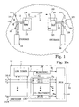
- FIG. 1 illustrates a typical system 1 , in which the present invention advantageously can be utilized.
- a transmitter 10 comprises an antenna 12 including associated hardware and software to be able to transmit radio signals 5 to a receiver 20 .
- the transmitter 10 comprises among other parts a multi-channel encoder 14 , which transforms signals of a number of input channels 16 into output signals suitable for radio transmission. Examples of suitable multi-channel encoders 14 are described in detail further below.
- the signals of the input channels 16 can be provided from e.g. an audio signal storage 18 , such as a data file of digital representation of audio recordings, magnetic tape or vinyl disc recordings of audio etc.
- the signals of the input channels 16 can also be provided in “live”, e.g. from a set of microphones 19 .
- the audio signals are digitized, if not already in digital form, before entering the multi-channel encoder 14 .
- an antenna 22 with associated hardware and software handles the actual reception of radio signals 5 representing polyphonic audio signals.
- typical functionalities such as e.g. error correction, are performed.
- a decoder 24 decodes the received radio signals 5 and transforms the audio data carried thereby into signals of a number of output channels 26 .
- the output signals can be provided to e.g. loudspeakers 29 for immediate presentation, or can be stored in an audio signal storage 28 of any kind.
- the system 1 can for instance be a phone conference system, a system for supplying audio services or other audio applications.
- the communication has to be of a duplex type, while e.g. distribution of music from a service provider to a subscriber can be essentially of a one-way type.
- the transmission of signals from the transmitter 10 to the receiver 20 can also be performed by any other means, e.g. by different kinds of electromagnetic waves, cables or fibers as well as combinations thereof.
- FIG. 2 a illustrates one embodiment of a multi-channel encoder 14 according to the present invention.
- a number of channel signals c 1 , c 2 , . . . , c N are received at separate inputs 16 : 1 - 16 :N.
- the channel signals are connected to a linear combination unit 34 .
- all channel signals are summed together to form a mono signal x.
- any predetermined linear combination of one or more of the channel signals may be used as an alternative, including pure channel signals.
- a pure sum will simplify most mathematical operations.
- the mono signal x is provided as an input signal 42 to a channel filter section 130 .
- the mono signal x is provided to, and encoded in, a mono signal encoder 38 to provide encoding parameters p x representing the mono signal x.
- the mono signal encoder operates according to any suitable mono signal encoding technique. Many such techniques are available in known technology. The actual details of the encoding technique are not of importance for enabling the present invention and is therefore not further discussed.
- the channel signals are also connected to the channel filter section 130 .
- each channel signal is connected to a respective filter adaptation unit 30 : 1 - 30 :N.
- the filter adaptation units perform a reconstruction of a respective channel signal when applied to the mono signal x.
- Coefficients of the filter adaptation units 30 : 1 - 30 :N are according to the present invention optimized under a perceptual constraint. However, the optimized coefficients of the filter adaptation units 30 : 1 - 30 :N may also be obtained at least partly in a joint optimization of two or more of the channel signals.
- the output of the channel filter section 130 comprises N sets of filter parameters p 1 -p N .
- These filter parameters p 1 -p N are typically encoded separately or jointly to be suitable for transmission.
- the filter parameters p 1 -p N and the mono signal x are sufficient to enable reconstruction of all channels signals.
- the encoded filter parameters p 1 -p N and the encoding parameters p x representing the mono signal x are in the present embodiment multiplexed in a multiplexor 40 into one output signal 52 , ready for transmission.
- FIG. 2 b illustrates one embodiment of a multi-channel decoder 24 according to the present invention.
- the decoder 24 in FIG. 2 b is suitable for decoding multi-channel signals encoded by the encoder of FIG. 2 a .
- An input signal 54 is received and provided to a demultiplexor 56 , which divides the input signal 54 into encoding parameters p x representing the mono signal x and a number of sets of encoded filter parameters p 1 -p N .
- the encoding parameters p x representing the mono signal x are provided to a mono signal decoder 64 , in which the encoding parameters p x representing the mono signal x are used to generate a decoded mono signal x′′ according any suitable decoding technique associated with the encoding technique used in FIG. 2 a . Many such techniques are available in known technology. The actual details of the decoding technique are not of importance for enabling the present invention and is therefore not further discussed.
- the decoded mono signal x′′ is provided to a channel filter section 160 .
- the encoded filter parameters are also provided to the channel filter section 160 , where they are decoded and used to define channel filters 60 : 1 - 60 :N.
- the so defined respective channel filters 60 : 1 - 60 :N are applied to the decoded mono signal x′′ whereby respective channel signals c′′ 1 -c′′ N are reconstructed and provided at outputs 26 : 1 - 26 :N.
- a mono signal is used as a main signal for regenerating the channel signals at the encoding or decoding.
- any predetermined linear combination of signals selected among the channel signals may be used as such a main signal.
- the optimum choice of predetermined linear combination depends on the actual application and implementation.
- a single channel signal can also constitute a possible such predetermined linear combination.
- FIG. 3 a Another embodiment of a multi-channel encoder 14 according to the present invention is illustrated in FIG. 3 a . Similar parts are denoted by similar reference numbers and only the differences are discussed below.
- the linear combination unit 34 provides as earlier a predetermined linear combination of the channel signals to the mono signal encoder 38 .
- the signal associated with the mono signal x is instead a decoded version x′′ of the encoding parameters p x representing the mono signal x.
- Such an arrangement referred to as a closed loop approach, will allow for certain compensations of mono signal encoding inaccuracies, as described further below.
- the linear combination unit 34 of the present embodiment also combines the channel signals in N ⁇ 1 predetermined linear combinations c* 1 -c* N-1 , which serves as actual input signals to the channel filter section 130 .
- the N-1 predetermined linear combinations c* 1 -c* N-1 should be mutually linear independent.
- the linear combinations c* 1 -c* N-1 do not necessarily comprise any contribution from all channel signals.
- the term “linear combination” should in this context be used as also comprising the special cases where a factor of a component can be set to zero. In fact, in the most simple set-up, the linear combinations c* 1 -c* N-1 can be identical to the channel signals c 1 -c N-1 . By utilizing a decoded mono signal x′′ at the decoder side, the original channel signals can be recovered.
- the modified channel signals are also in this embodiment connected to the channel filter section 130 , in which N ⁇ 1 sets of filter coefficients are deduced, now corresponding to the modified channel signals.
- the coefficients of the filter adaptation units 30 : 1 - 30 :N are according to the present invention optimized under a perceptual constraint.
- the output of the channel filter section 130 comprises N ⁇ 1 sets of filter parameters p* 1 -p* N-1 .
- These filter parameters p* 1 -p N-1 are typically encoded separately or jointly to be suitable for transmission.
- the encoded filter parameters p* 1 -p* N-1 and the encoding parameters p x representing the mono signal x are in the present embodiment transmitted separately.
- FIG. 3 b illustrates another embodiment of a multi-channel decoder 24 according to the present invention.
- the decoder 24 in FIG. 3 b is suitable for decoding multi-channel signals encoded by the encoder of FIG. 3 a .
- Encoding parameters p x representing the mono signal x and a set of encoded filter parameters p* 1 -p* N-1 are received.
- the encoding parameters p x representing the mono signal x are used to generate a decoded mono signal x′′ in a mono signal decoder 64 in analogy with previous embodiment.
- the filter parameters p* 1 -p* N-1 are likewise provided to the channel filter section 160 for obtaining N ⁇ 1 decoded modified channel signals c* 1 -c* N-1 .
- a linear combination unit 74 is then used to provide reconstructed channel signals c′′ 1 -c′′ N from the modified channel signals c* 1 -c* N-1 and the decoded mono signal x′′.
- This error is expressed as:
- the perceptual characteristics may not completely be determined by a pure mathematical minimization.
- the predicted channels may have no frequency content above or below a certain frequency. This occurs if, for instance, the channel is high-pass filtered, or results from a band-splitting procedure. Spectral nulls may cause instabilities and lead to filter responses that produces unnecessary amplification and low frequency audible artifacts. According to the present invention, a shape constraint is therefore advantageously utilized during optimization procedures.
- FIG. 4 illustrates the basic ideas of the constrained minimization procedure at the encoder side according to the present invention in an embodiment having two channels (the stereo case) and a linear filter 31 .
- a filter 31 responsive for reconstruction of channel c 1 having filter coefficients h c1 is derived according to a constrained error minimization procedure in an optimizing unit 32 .
- the factors ⁇ c1 and ⁇ c2 determine how the channel signals are combined.
- One possibility is to set ⁇ c1 to a factor 2 ⁇ and ⁇ c2 to 2(1 ⁇ ).
- the mono signal will be a weighted sum of the channels.
- the weighted combination of the individual channel signals to form the mono signal can in general even be the combination of filtered versions of the respective channel signals. Such an approach will be called pre-filtering.
- the channels can be pre-filtered by a LPC (Linear Predictive Coding) residual filter of the mono signal.
- LPC Linear Predictive Coding
- the mono and left and right channel will be assumed to be in general some pre-filtered versions of the real mono, left and right channels.
- the step of post-filtering with the mono LPC synthesis filter would be needed in order to get back to the signal domains.
- ⁇ 1(n) is a linear combination of delayed versions of signal x(n):
- the filter parameters p 1 comprise the filter coefficients h c1 and maybe necessary additional data defining the filter.
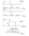
- the difference signal of two channel signals is reproduced by a filter.
- the right and left signals are illustrated by the curves 301 and 302 , respectively.
- the representation is not ideal, giving a slightly larger difference than the target difference over the entire frame. This will lead to a reproduced right signal 303 at the decoder side that is slightly lower than the original right signal, and a reproduced left signal 304 that is slightly higher than the original left signal.
- the perception of such an artifact is that the volume of the right channel is decreased and the volume of the left channel is increased. If such artifacts moreover vary in time, the sound will swing back and forth between the right and left channel. A gain constraint may improve such a situation.
- One possible approach is to have a hard constraint, i.e. exact energy match between the original channel and the estimated channel, or to impose a loose gain constraint such as the output channel has a prescribed energy E c1 , which is not necessarily equal to the original channel signal energy.
- the constrained minimization problem can easily be solved by Lagrange method, i.e. the Lagrange functional:
- a channel signal may look like curve 305 of FIG. 6 . No intensity is present below frequency f 1 or above frequency f 2 . However, a pure mathematical optimization gives rise to a curve 306 , which presents some limited power also below and above the frequencies f 1 and f 2 , respectively. Such artifacts are perceived.
- constraints In order to impose a certain spectral shape on the filter, a set of linear constraints have to be imposed on the filter. These constraints should in general be of a number less than the number of coefficients of the filter.
- the shape constraint can be formulated by a matrix and a vector such that
- h _ c uc h _ c uc + R _ _ xx - 1 ⁇ W _ _ c ⁇ [ W _ _ c T ⁇ R _ _ xx - 1 ⁇ W _ _ c ] - 1 ⁇ ( ⁇ w _ c - W _ _ c T ⁇ h _ c uc ⁇ ) .
- This constraint is especially useful when it is known a priori that the channel has no frequency content in a certain frequency range.
- the gain and shape constraints can also be combined.
- the shape constraint is preferably first applied and the gain constraint is then added as a factor, according to
- This equation is useful for bit rate reduction when encoding the channel filters, since it shows that the channel filters are related by quantities that are available at the decoder side.
- FIG. 7 an illustration shows that one c 1 out of two channels c 1 , c 2 is reproduced by applying the mono signal x to an unconstrained filter 131 .
- the result of the unconstrained filter is modified depending on shape constraints in a shape constraint section 132 .
- the shape constrained filter of channel c 2 can be calculated and provided to separate gain constraint sections 133 for each channel.
- FIG. 8 A more detailed block scheme of another embodiment using a side signal for applying the shape constraint is illustrated in FIG. 8 .
- Two channel signals c 1 and c 2 are combined in addition means 55 , 57 of a linear combination unit 34 to a mono signal x and a side signal s.
- a channel filter section 130 comprises an unconstrained parametric filter 131 , which applied to the mono signal x reproduces an estimate of the side signal s .
- the filter coefficients are adapted to give the minimum difference between s and ⁇ .
- the filter obtained in this manner h s uc is provided to a shape constraint section 132 , basically according to the discussions further above.
- a shape-constrained filter h uc for the side signal is created.
- a shape-constrained filter for each channel signal is calculated, based on the shape-constrained filter h s sc for the side signal.
- These filters, or rather the coefficients thereof, are provided to a respective gain constraint section 133 : 1 , 133 : 2 .
- a gain factor for each channel signal is calculated, and the two filters are provided to a parameter encoding section 66 , where the parameters of the two filters are jointly encoded.
- the constrained channel filters h c1 and h c2 After calculation of the constrained channel filters h c1 and h c2 , they are quantized and encoded in a representation, which is suitable for transmission to the receiver. Typically, the coefficients of the filters are quantized using scalar or vector quantizers and the quantizer indexes are transmitted. The quantizers may also implement prediction, which is very beneficial for bit rate reduction especially in this scenario.
- Making use of the complementarities of the filters may further reduce the bit rate since only one of the filters h c1 or h c2 or a linear combination of them is quantized and transmitted while the gains g c1 and g c2 are jointly vector quantized and transmitted separately. Such a transmission can be carried out at bit rates as low as, e.g. 1 kbps.
- the receiver first decodes the transmitted mono signal and channel filters. Then, it regenerates the different channel signals by filtering the mono signal through the respective channel filter. Preferably, in the stereo case, the completeness property is used, and the coefficients are recombined to produce the filters h c1 and h c2 .
- Certain post-processing steps that further improve the quality of the reconstructed multi-channel signal may follow the re-generation of the different channels signals.
- the gain constraint on the filters assumes previously computed channel energies, i.e. E c1 , E c2 . It is important to control the gains of the filters, e.g. g c1 , g c2 and to avoid unnecessary amplification by limiting the gains. Depending on the properties of the different channel signals, it may occur that the channels are anti-correlated on the whole frequency range or in certain frequency bands. This leads to a certain cancellation when the mono channel is formed. In this case, since the individual channel information has been lost, at least partially and in some frequency bands, it is often beneficial to limit the channels gains when these are greater than a certain amount, e.g. 0 dB. One way to perform this gain limitation is to compute a certain gain factor:
- this factor is less than 0 dB, then we have signal cancellation.
- g F quantifies how severe this cancellation is.
- the filters are derived based on the original mono signal. This is e.g. the case in FIG. 2 a , where the signal 42 is the original mono signal x.
- the decoder will use a quantized mono signal as input for the channel filtering.
- the filter calculations are based on the coded and thus already quantized mono signal. This is e.g. the case in FIG. 3 a , where the signal 44 is a decoded mono signal x′′.
- This approach has the advantage that the channel filter design does not only aim to match the respective channel signals in a best possible way. It also aims to mitigate coding errors, which are the result of the mono signal encoding.
- FIG. 9 illustrates the principles of sub-band processing.
- a number of channels c 1 -c N are each divided in K sub-bands SB 1 , SB 2 , SBK.
- the channel signals in each sub-band is provided to a respective multi-channel encoder unit 80 : 1 - 80 :K, where the channel signals are encoded.
- One or several of the multi-channel encoder units 80 : 1 - 80 :K can be multi-channel encoder units according to the present invention.
- a bit-stream combiner 82 combines the encoded signals into a common encoded signal 53 , that is transmitted.
- the multi-channel encoding for the different sub-bands can be carried out individually optimized with respect to e.g. assigned bit rate, processing frame sizes and sampling rate.
- sub-band processing does not carry out multi-channel encoding for very low frequencies, e.g. below 200 Hz. That means that for this very low frequency band, a mere mono signal is transmitted. This principle makes use of the fact that the human stereo perception is less sensitive for very low frequencies. It is known from prior art and called sub-woofing.
- the band splitting is done using a time-frequency transform such as, e.g. a short term Fourier transform (STFT), which allows decomposing the signal into single frequency components.
- STFT short term Fourier transform
- the filtering reduces to a mere multiplication of the individual spectral coefficients of the mono signal with a complex factor.
- the parametric multi-channel coding method according to the invention will typically involve fixed frame-wise processing of signal samples.
- parameters describing the multi-channel image are derived and transmitted with a rate corresponding to a coding frame length of, e.g. 20 ms.
- the parameters may, however, be obtained from signal frames which are much larger than the coding frame length.
- a suitable choice is to set the length of such analysis frames to values larger than the coding frame length. This implies that the parameter calculation is performed with overlapping analysis frames.
- Analysis frames 83 at the encoder are slightly longer than encoding frames 84 , as shown in the top of the figure.
- a consequence of such overlapping analysis frames is that the parameters evolve smoothly, which is essential in order to provide a stable multi-channel audio signal impression.
- the same is performed at the decoder side, shown in the middle of the figure. It is thus essential in the decoder to take account of this and to window and overlap-add synthesis frames 85 , with an overlap 86 , as shown at the bottom of the figure. This allows a smooth transition between filters associated with each frame.
- smooth filter parameter evolution can be enforced. It is, e.g. possible to apply low-pass or median filtering to the filter parameters.
- noise shaping of the coding noise.
- the purpose of this operation is to move coding noise to frequencies where the signal has high spectral density and thus render the noise less audible.
- Noise shaping is usually done adaptively, i.e. in response to the audio signal. This implies that, in general, the noise shaping performed on the mono signal will be different from what is required for the various channel signals.
- the subsequent channel filtering according to the invention may lead to an audible coding noise increase in the reconstructed multi-channel signal when comparing to the audible coding noise in the mono signal.
- signal-adaptive post-filtering may be applied to the reconstructed channel signals in a post-processing step of the receiver.
- Any state-of-the-art post-filtering techniques can be deployed here, which essentially emphasize spectral tops or deepen spectral valleys and thereby reduce the audible noise.
- One example of such a technique is so-called high-resolution post-filtering which is described in the European Patent 0 965 123 B1 by E. Ekudden et. al.
- Other simple methods are so-called pitch- and formant post-filters, which are known from speech coding.
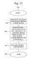
- step 200 a main signal, preferably a mono signal, deduced from the multi-channel signals is encoded.
- filter coefficients are optimized to give an as good representation as possible of a channel signal when applied to the main signal. The optimizing takes place under perceptual constraints. The optimal coefficients are then encoded in step 224 .
- the procedure ends in step 299 .
Abstract
Description
R xx ·h c uc =r xc
where R xx is the symmetric covariance matrix of the mono signal x(n):
and where r xc is a vector of cross-correlations of signals x(n) and c(n):
x(n)=γc1 ·c1(n)+γc2 ·c2(n),
and derives from it the output signal ĉ1(n). The factors γc1 and γc2 determine how the channel signals are combined. One possibility is to set γc1 to a factor 2γ and γc2 to 2(1−γ). In this case, the mono signal will be a weighted sum of the channels. In particular, a suitable setting is γ=0.5, in which case both channels are equally weighted. Another suitable setting may be γc1=−γc2, in which case the mono signal is the difference of the channel signals.
the index set being I=[imin . . . imax]. The filter parameters p1 comprise the filter coefficients h c1 and maybe necessary additional data defining the filter.
where δ denotes the identity filter. Useful properties can be derived for the shape-constrained filters, if the constraints on the two channels are identical,
h s sc=0.5 h c1 sc−0.5 h c2 sc
and in order to reduce possible artifacts, the gain difference of this filter between successive frames is smoothened leading to a filter otl h s sc. The channel filters are then modified according to:
otl h c1 sc =δ+otl h s sc
otl h c2 sc =δ−otl h s sc.
which is the ratio of the effective mono channel energy and the energy of the mono channel if the two channels were uncorrelated. When this factor is less than 0 dB, then we have signal cancellation. In this case, gF quantifies how severe this cancellation is. The gain limitation can then be computed as:
g c1(dB)=max(g c1(dB)+g F(dB),0), when gF<0 dB.
- U.S. Pat. No. 5,285,498
- U.S. Pat. No. 5,434,948
- European patent 0 497 413
- European Patent 0 965 123
- International patent application WO 03/090206
- “Binaural cue coding applied to stereo and multi-channel audio compression”, 112th AES convention, May 2002, Munich, Germany by C. Faller et al.
Claims (19)
Priority Applications (1)
| Application Number | Priority Date | Filing Date | Title |
|---|---|---|---|
| US11/011,764 US7725324B2 (en) | 2003-12-19 | 2004-12-15 | Constrained filter encoding of polyphonic signals |
Applications Claiming Priority (5)
| Application Number | Priority Date | Filing Date | Title |
|---|---|---|---|
| US53065003P | 2003-12-19 | 2003-12-19 | |
| SE0400415-6 | 2004-02-20 | ||
| SE0400415 | 2004-02-20 | ||
| SE0400415A SE527713C2 (en) | 2003-12-19 | 2004-02-20 | Coding of polyphonic signals with conditional filters |
| US11/011,764 US7725324B2 (en) | 2003-12-19 | 2004-12-15 | Constrained filter encoding of polyphonic signals |
Publications (2)
| Publication Number | Publication Date |
|---|---|
| US20050160126A1 US20050160126A1 (en) | 2005-07-21 |
| US7725324B2 true US7725324B2 (en) | 2010-05-25 |
Family
ID=34753531
Family Applications (1)
| Application Number | Title | Priority Date | Filing Date |
|---|---|---|---|
| US11/011,764 Active 2028-07-17 US7725324B2 (en) | 2003-12-19 | 2004-12-15 | Constrained filter encoding of polyphonic signals |
Country Status (1)
| Country | Link |
|---|---|
| US (1) | US7725324B2 (en) |
Cited By (9)
| Publication number | Priority date | Publication date | Assignee | Title |
|---|---|---|---|---|
| US20060246868A1 (en) * | 2005-02-23 | 2006-11-02 | Telefonaktiebolaget Lm Ericsson (Publ) | Filter smoothing in multi-channel audio encoding and/or decoding |
| US20080262850A1 (en) * | 2005-02-23 | 2008-10-23 | Anisse Taleb | Adaptive Bit Allocation for Multi-Channel Audio Encoding |
| US20090041255A1 (en) * | 2005-02-01 | 2009-02-12 | Matsushita Electric Industrial Co., Ltd. | Scalable encoding device and scalable encoding method |
| US20090083045A1 (en) * | 2006-03-15 | 2009-03-26 | Manuel Briand | Device and Method for Graduated Encoding of a Multichannel Audio Signal Based on a Principal Component Analysis |
| US20090083044A1 (en) * | 2006-03-15 | 2009-03-26 | France Telecom | Device and Method for Encoding by Principal Component Analysis a Multichannel Audio Signal |
| US20100046760A1 (en) * | 2006-12-28 | 2010-02-25 | Alexandre Delattre | Audio encoding method and device |
| US20100094640A1 (en) * | 2006-12-28 | 2010-04-15 | Alexandre Delattre | Audio encoding method and device |
| US20120076307A1 (en) * | 2009-06-05 | 2012-03-29 | Koninklijke Philips Electronics N.V. | Processing of audio channels |
| US20220392468A1 (en) * | 2005-02-14 | 2022-12-08 | Fraunhofer-Gesellschaft Zur Foerderung Der Angewandten Forschung E.V. | Parametric joint-coding of audio sources |
Families Citing this family (7)
| Publication number | Priority date | Publication date | Assignee | Title |
|---|---|---|---|---|
| KR20070092240A (en) * | 2004-12-27 | 2007-09-12 | 마츠시타 덴끼 산교 가부시키가이샤 | Sound coding device and sound coding method |
| JP4842147B2 (en) * | 2004-12-28 | 2011-12-21 | パナソニック株式会社 | Scalable encoding apparatus and scalable encoding method |
| US7729673B2 (en) * | 2004-12-30 | 2010-06-01 | Sony Ericsson Mobile Communications Ab | Method and apparatus for multichannel signal limiting |
| US20070133819A1 (en) * | 2005-12-12 | 2007-06-14 | Laurent Benaroya | Method for establishing the separation signals relating to sources based on a signal from the mix of those signals |
| US8027479B2 (en) | 2006-06-02 | 2011-09-27 | Coding Technologies Ab | Binaural multi-channel decoder in the context of non-energy conserving upmix rules |
| JPWO2008016098A1 (en) * | 2006-08-04 | 2009-12-24 | パナソニック株式会社 | Stereo speech coding apparatus, stereo speech decoding apparatus, and methods thereof |
| TWI559679B (en) | 2009-02-18 | 2016-11-21 | 杜比國際公司 | Low delay modulated filter bank and method for the design of the low delay modulated filter bank |
Citations (23)
| Publication number | Priority date | Publication date | Assignee | Title |
|---|---|---|---|---|
| EP0497413A1 (en) | 1991-02-01 | 1992-08-05 | Koninklijke Philips Electronics N.V. | Subband coding system and a transmitter comprising the coding system |
| EP0559383A1 (en) | 1992-03-02 | 1993-09-08 | AT&T Corp. | A method and apparatus for coding audio signals based on perceptual model |
| US5434948A (en) * | 1989-06-15 | 1995-07-18 | British Telecommunications Public Limited Company | Polyphonic coding |
| US5694332A (en) | 1994-12-13 | 1997-12-02 | Lsi Logic Corporation | MPEG audio decoding system with subframe input buffering |
| US5812971A (en) * | 1996-03-22 | 1998-09-22 | Lucent Technologies Inc. | Enhanced joint stereo coding method using temporal envelope shaping |
| JPH1132399A (en) | 1997-05-13 | 1999-02-02 | Sony Corp | Coding method and system and recording medium |
| US5956674A (en) * | 1995-12-01 | 1999-09-21 | Digital Theater Systems, Inc. | Multi-channel predictive subband audio coder using psychoacoustic adaptive bit allocation in frequency, time and over the multiple channels |
| EP0965123A1 (en) | 1997-03-03 | 1999-12-22 | TELEFONAKTIEBOLAGET L M ERICSSON (publ) | A high resolution post processing method for a speech decoder |
| JP2001184090A (en) | 1999-12-27 | 2001-07-06 | Fuji Techno Enterprise:Kk | Signal encoding device and signal decoding device, and computer-readable recording medium with recorded signal encoding program and computer-readable recording medium with recorded signal decoding program |
| US6341165B1 (en) * | 1996-07-12 | 2002-01-22 | Fraunhofer-Gesellschaft zur Förderdung der Angewandten Forschung E.V. | Coding and decoding of audio signals by using intensity stereo and prediction processes |
| JP2002132295A (en) | 2000-10-27 | 2002-05-09 | Matsushita Electric Ind Co Ltd | Stereoaudio signal high-performance encoder system |
| US6446037B1 (en) * | 1999-08-09 | 2002-09-03 | Dolby Laboratories Licensing Corporation | Scalable coding method for high quality audio |
| JP2002255899A (en) | 2001-03-01 | 2002-09-11 | Asahi Denka Kogyo Kk | Fluorocarboxylic acid phenyl ester compound |
| US20030061055A1 (en) | 2001-05-08 | 2003-03-27 | Rakesh Taori | Audio coding |
| US20030115052A1 (en) | 2001-12-14 | 2003-06-19 | Microsoft Corporation | Adaptive window-size selection in transform coding |
| US20030115041A1 (en) | 2001-12-14 | 2003-06-19 | Microsoft Corporation | Quality improvement techniques in an audio encoder |
| US6591241B1 (en) * | 1997-12-27 | 2003-07-08 | Stmicroelectronics Asia Pacific Pte Limited | Selecting a coupling scheme for each subband for estimation of coupling parameters in a transform coder for high quality audio |
| WO2003090208A1 (en) | 2002-04-22 | 2003-10-30 | Koninklijke Philips Electronics N.V. | pARAMETRIC REPRESENTATION OF SPATIAL AUDIO |
| WO2003090206A1 (en) | 2002-04-22 | 2003-10-30 | Koninklijke Philips Electronics N.V. | Signal synthesizing |
| JP2003345398A (en) | 2002-05-27 | 2003-12-03 | Matsushita Electric Ind Co Ltd | Audio signal encoding method |
| US7340391B2 (en) * | 2004-03-01 | 2008-03-04 | Fraunhofer-Gesellschaft Zur Foerderung Der Angewandten Forschung E.V. | Apparatus and method for processing a multi-channel signal |
| US7356748B2 (en) | 2003-12-19 | 2008-04-08 | Telefonaktiebolaget Lm Ericsson (Publ) | Partial spectral loss concealment in transform codecs |
| US7437299B2 (en) * | 2002-04-10 | 2008-10-14 | Koninklijke Philips Electronics N.V. | Coding of stereo signals |
Family Cites Families (3)
| Publication number | Priority date | Publication date | Assignee | Title |
|---|---|---|---|---|
| US6272456B1 (en) * | 1998-03-19 | 2001-08-07 | Microsoft Corporation | System and method for identifying the language of written text having a plurality of different length n-gram profiles |
| US6311152B1 (en) * | 1999-04-08 | 2001-10-30 | Kent Ridge Digital Labs | System for chinese tokenization and named entity recognition |
| US7451125B2 (en) * | 2004-11-08 | 2008-11-11 | At&T Intellectual Property Ii, L.P. | System and method for compiling rules created by machine learning program |
-
2004
- 2004-12-15 US US11/011,764 patent/US7725324B2/en active Active
Patent Citations (25)
| Publication number | Priority date | Publication date | Assignee | Title |
|---|---|---|---|---|
| US5434948A (en) * | 1989-06-15 | 1995-07-18 | British Telecommunications Public Limited Company | Polyphonic coding |
| EP0497413A1 (en) | 1991-02-01 | 1992-08-05 | Koninklijke Philips Electronics N.V. | Subband coding system and a transmitter comprising the coding system |
| EP0559383A1 (en) | 1992-03-02 | 1993-09-08 | AT&T Corp. | A method and apparatus for coding audio signals based on perceptual model |
| US5285498A (en) | 1992-03-02 | 1994-02-08 | At&T Bell Laboratories | Method and apparatus for coding audio signals based on perceptual model |
| US5694332A (en) | 1994-12-13 | 1997-12-02 | Lsi Logic Corporation | MPEG audio decoding system with subframe input buffering |
| US6487535B1 (en) | 1995-12-01 | 2002-11-26 | Digital Theater Systems, Inc. | Multi-channel audio encoder |
| US5956674A (en) * | 1995-12-01 | 1999-09-21 | Digital Theater Systems, Inc. | Multi-channel predictive subband audio coder using psychoacoustic adaptive bit allocation in frequency, time and over the multiple channels |
| US5812971A (en) * | 1996-03-22 | 1998-09-22 | Lucent Technologies Inc. | Enhanced joint stereo coding method using temporal envelope shaping |
| US6341165B1 (en) * | 1996-07-12 | 2002-01-22 | Fraunhofer-Gesellschaft zur Förderdung der Angewandten Forschung E.V. | Coding and decoding of audio signals by using intensity stereo and prediction processes |
| EP0965123A1 (en) | 1997-03-03 | 1999-12-22 | TELEFONAKTIEBOLAGET L M ERICSSON (publ) | A high resolution post processing method for a speech decoder |
| JPH1132399A (en) | 1997-05-13 | 1999-02-02 | Sony Corp | Coding method and system and recording medium |
| US6591241B1 (en) * | 1997-12-27 | 2003-07-08 | Stmicroelectronics Asia Pacific Pte Limited | Selecting a coupling scheme for each subband for estimation of coupling parameters in a transform coder for high quality audio |
| US6446037B1 (en) * | 1999-08-09 | 2002-09-03 | Dolby Laboratories Licensing Corporation | Scalable coding method for high quality audio |
| JP2001184090A (en) | 1999-12-27 | 2001-07-06 | Fuji Techno Enterprise:Kk | Signal encoding device and signal decoding device, and computer-readable recording medium with recorded signal encoding program and computer-readable recording medium with recorded signal decoding program |
| JP2002132295A (en) | 2000-10-27 | 2002-05-09 | Matsushita Electric Ind Co Ltd | Stereoaudio signal high-performance encoder system |
| JP2002255899A (en) | 2001-03-01 | 2002-09-11 | Asahi Denka Kogyo Kk | Fluorocarboxylic acid phenyl ester compound |
| US20030061055A1 (en) | 2001-05-08 | 2003-03-27 | Rakesh Taori | Audio coding |
| US20030115041A1 (en) | 2001-12-14 | 2003-06-19 | Microsoft Corporation | Quality improvement techniques in an audio encoder |
| US20030115052A1 (en) | 2001-12-14 | 2003-06-19 | Microsoft Corporation | Adaptive window-size selection in transform coding |
| US7437299B2 (en) * | 2002-04-10 | 2008-10-14 | Koninklijke Philips Electronics N.V. | Coding of stereo signals |
| WO2003090208A1 (en) | 2002-04-22 | 2003-10-30 | Koninklijke Philips Electronics N.V. | pARAMETRIC REPRESENTATION OF SPATIAL AUDIO |
| WO2003090206A1 (en) | 2002-04-22 | 2003-10-30 | Koninklijke Philips Electronics N.V. | Signal synthesizing |
| JP2003345398A (en) | 2002-05-27 | 2003-12-03 | Matsushita Electric Ind Co Ltd | Audio signal encoding method |
| US7356748B2 (en) | 2003-12-19 | 2008-04-08 | Telefonaktiebolaget Lm Ericsson (Publ) | Partial spectral loss concealment in transform codecs |
| US7340391B2 (en) * | 2004-03-01 | 2008-03-04 | Fraunhofer-Gesellschaft Zur Foerderung Der Angewandten Forschung E.V. | Apparatus and method for processing a multi-channel signal |
Non-Patent Citations (13)
| Title |
|---|
| Canadian official action, Jun. 17, 2008, in corresponding Canadian Application No. 2,527,971. |
| Christof Faller and Frank Baumgarte; "Binaural Cue Coding Applied to Stereo and Multi-Channel Audio Compression;" AES Convention Paper 5574, 112th Convention, Munich, Germany, May 10-13, 2002. |
| Christof Faller and Frank Baumgarte; "Efficient Representation of Spatial Audio Using Perceptual Parametrization;" Applications of Signal Processing to Audio and Acoustics; 2001 IEEE Workshop on Publication date Oct. 21-24, 2001; pp. W2001-1 through W2001-4. |
| European official action, Feb. 22, 2010, in corresponding European Application No. 04 809 080.7-225. |
| Herre, J. et al., Intensity Stereo Coding, AES Convention: 96 (Feb. 1994) Paper No. 3799; Affiliation: Fraunhofer Gesellschaft, Institute fur Integrierte Schaultungen, Erlangen, Germany. |
| International Search Report and Written Opinion mailed Mar. 17, 2005 in corresponding PCT Application PCT/SE2004/001907. |
| Japanese official action, dated May 7, 2008 in corresponding Japanese Application No. 2006-518596. |
| L.R. Rabiner et al., Digital Processing of Speech Signals, Upper Saddle River, New Jersey: Prentice Hall, Inc., 1978, pp. 116-130. |
| Office action mailed Jan. 26, 2009 in co-pending U.S. Appl. No. 11/011,765. |
| Office Action mailed Jul. 31, 2009 in co-pending U.S. Appl. No. 11/011,765. |
| Oomen, Werner; Schuijers, Erik; den Brinker, Bert; Breebaart, Jeroen. Advances in Parametric Coding for High-Quality Audio. Philips Digital Systems Laboratories, Eindhoven, The Netherlands ; Philips Research Laboratories, Eindhoven, The Netherlands, AES Convention:114 (Mar. 2003). * |
| Summary of the Japanese official action, dated May 7, 2008 in corresponding Japanese Application No. 2006-518596. |
| U.S. Appl. No. 11/011,765, filed Dec. 15, 2004; Inventor: Johansson et al. |
Cited By (21)
| Publication number | Priority date | Publication date | Assignee | Title |
|---|---|---|---|---|
| US20090041255A1 (en) * | 2005-02-01 | 2009-02-12 | Matsushita Electric Industrial Co., Ltd. | Scalable encoding device and scalable encoding method |
| US8036390B2 (en) * | 2005-02-01 | 2011-10-11 | Panasonic Corporation | Scalable encoding device and scalable encoding method |
| US20220392466A1 (en) * | 2005-02-14 | 2022-12-08 | Fraunhofer-Gesellschaft Zur Foerderung Der Angewandten Forschung E.V. | Parametric joint-coding of audio sources |
| US20220392468A1 (en) * | 2005-02-14 | 2022-12-08 | Fraunhofer-Gesellschaft Zur Foerderung Der Angewandten Forschung E.V. | Parametric joint-coding of audio sources |
| US20220392467A1 (en) * | 2005-02-14 | 2022-12-08 | Fraunhofer-Gesellschaft Zur Foerdering Der Angewandten Forschung E.V. | Parametric joint-coding of audio sources |
| US11621005B2 (en) * | 2005-02-14 | 2023-04-04 | Fraunhofer-Gesellschaft Zur Foerderung Der Angewandten Forschung E.V. | Parametric joint-coding of audio sources |
| US11621007B2 (en) * | 2005-02-14 | 2023-04-04 | Fraunhofer-Gesellschaft Zur Foerderung Der Angewandten Forschung E.V. | Parametric joint-coding of audio sources |
| US11621006B2 (en) * | 2005-02-14 | 2023-04-04 | Fraunhofer-Gesellschaft Zur Foerderung Der Angewandten Forschung E.V. | Parametric joint-coding of audio sources |
| US20080262850A1 (en) * | 2005-02-23 | 2008-10-23 | Anisse Taleb | Adaptive Bit Allocation for Multi-Channel Audio Encoding |
| US20060246868A1 (en) * | 2005-02-23 | 2006-11-02 | Telefonaktiebolaget Lm Ericsson (Publ) | Filter smoothing in multi-channel audio encoding and/or decoding |
| US7945055B2 (en) | 2005-02-23 | 2011-05-17 | Telefonaktiebolaget Lm Ericcson (Publ) | Filter smoothing in multi-channel audio encoding and/or decoding |
| US9626973B2 (en) | 2005-02-23 | 2017-04-18 | Telefonaktiebolaget L M Ericsson (Publ) | Adaptive bit allocation for multi-channel audio encoding |
| US20090083044A1 (en) * | 2006-03-15 | 2009-03-26 | France Telecom | Device and Method for Encoding by Principal Component Analysis a Multichannel Audio Signal |
| US8370134B2 (en) * | 2006-03-15 | 2013-02-05 | France Telecom | Device and method for encoding by principal component analysis a multichannel audio signal |
| US8359194B2 (en) * | 2006-03-15 | 2013-01-22 | France Telecom | Device and method for graduated encoding of a multichannel audio signal based on a principal component analysis |
| US20090083045A1 (en) * | 2006-03-15 | 2009-03-26 | Manuel Briand | Device and Method for Graduated Encoding of a Multichannel Audio Signal Based on a Principal Component Analysis |
| US20100046760A1 (en) * | 2006-12-28 | 2010-02-25 | Alexandre Delattre | Audio encoding method and device |
| US8595017B2 (en) | 2006-12-28 | 2013-11-26 | Mobiclip | Audio encoding method and device |
| US8340305B2 (en) * | 2006-12-28 | 2012-12-25 | Mobiclip | Audio encoding method and device |
| US20100094640A1 (en) * | 2006-12-28 | 2010-04-15 | Alexandre Delattre | Audio encoding method and device |
| US20120076307A1 (en) * | 2009-06-05 | 2012-03-29 | Koninklijke Philips Electronics N.V. | Processing of audio channels |
Also Published As
| Publication number | Publication date |
|---|---|
| US20050160126A1 (en) | 2005-07-21 |
Similar Documents
| Publication | Publication Date | Title |
|---|---|---|
| US9812136B2 (en) | Audio processing system | |
| KR100954179B1 (en) | Near-transparent or transparent multi-channel encoder/decoder scheme | |
| KR102168140B1 (en) | Audio upmixer operable in prediction or non-prediction mode | |
| CA2527971C (en) | Fidelity-optimised variable frame length encoding | |
| KR100947013B1 (en) | Temporal and spatial shaping of multi-channel audio signals | |
| US8046214B2 (en) | Low complexity decoder for complex transform coding of multi-channel sound | |
| US7885819B2 (en) | Bitstream syntax for multi-process audio decoding | |
| KR101183857B1 (en) | Method and apparatus to encode and decode multi-channel audio signals | |
| US8249883B2 (en) | Channel extension coding for multi-channel source | |
| US7809579B2 (en) | Fidelity-optimized variable frame length encoding | |
| US7725324B2 (en) | Constrained filter encoding of polyphonic signals | |
| KR20090007396A (en) | Method and apparatus for lossless encoding of a source signal, using a lossy encoded data stream and a lossless extension data stream | |
| EP1639580B1 (en) | Coding of multi-channel signals | |
| AU2018200340A1 (en) | Advanced stereo coding based on a combination of adaptively selectable left/right or mid/side stereo coding and of parametric stereo coding | |
| MX2008009186A (en) | Complex-transform channel coding with extended-band frequency coding |
Legal Events
| Date | Code | Title | Description |
|---|---|---|---|
| AS | Assignment |
Owner name: TELEFONAKTIEBOLAGET L M ERICSSON (PUBL),SWEDEN Free format text: ASSIGNMENT OF ASSIGNORS INTEREST;ASSIGNORS:TALEB ANISSE;JOHANSSON, INGEMAR;BRUHN, STEFAN;AND OTHERS;SIGNING DATES FROM 20050407 TO 20050411;REEL/FRAME:016517/0628 Owner name: TELEFONAKTIEBOLAGET L M ERICSSON (PUBL), SWEDEN Free format text: ASSIGNMENT OF ASSIGNORS INTEREST;ASSIGNORS:TALEB ANISSE;JOHANSSON, INGEMAR;BRUHN, STEFAN;AND OTHERS;REEL/FRAME:016517/0628;SIGNING DATES FROM 20050407 TO 20050411 |
|
| STCF | Information on status: patent grant |
Free format text: PATENTED CASE |
|
| CC | Certificate of correction | ||
| FPAY | Fee payment |
Year of fee payment: 4 |
|
| MAFP | Maintenance fee payment |
Free format text: PAYMENT OF MAINTENANCE FEE, 8TH YEAR, LARGE ENTITY (ORIGINAL EVENT CODE: M1552) Year of fee payment: 8 |
|
| MAFP | Maintenance fee payment |
Free format text: PAYMENT OF MAINTENANCE FEE, 12TH YEAR, LARGE ENTITY (ORIGINAL EVENT CODE: M1553); ENTITY STATUS OF PATENT OWNER: LARGE ENTITY Year of fee payment: 12 |