CROSS-REFERENCE TO RELATED APPLICATION
This is the priority-claiming application with reference to JP2005-111020 filed on Apr. 7, 2005, based upon U.S. Patent Law, the Article 119 on claiming foreign priority. The following U.S. patent application is hereby incorporated by reference in its entirety as though fully and completely set forth herein: JP2005-111020, filed on Apr. 7, 2005.
BACKGROUND OF THE INVENTION
1. Field of the Invention
The present invention relates to a multiple freedom manipulator preferable to forceps for use in low invasion operation or the like.
2. Description of the Related Art
Low invasion operations attract many attentions in the field of medical operation and have been introduced into the same in recent years. Although in conventional operations a body of a patient is largely cut as in abdominal surgery the low invasion operation is an operation which is realized only by cutting a body as possible as slightly and in which an operator treats a diseased part by inserting an elongated rod-shaped forceps and a surgical knife while observing the diseased part mainly with the aid of an endoscope.
The low invasion operation cures diseases by inserting an elongated rod-shaped forceps and a surgical knife from a small hole while watching a diseased part using an endoscope as described above, so that any damage of a normal portion can be reduced to make a contribution to patients, but, on the one hand, there are problems to make difficult the operation of a treatment tool because the tool is restricted by the hole. To solve the problem a forceps capable of moving the tip end of the forceps are now in studies and developments.
As treatment tools having flexibility at the tip end of a forceps there have been hitherto proposed a forceps disclosed in reference 1 having one-degree-of-freedom of rotation without actuator and a master/slave forceps disclosed in reference 2 having two-degree-of-freedom and gripping.
However, in order to take an arbitrary attitude the tip end of the forceps requires two or more-degree-of-freedom so that the forceps disclosed in reference 1 does not provide enough operationability.
Further, the forceps disclosed in reference 2 suffers from a difficulty that introduction and operation thereof are difficult in view of the magnitude and costs thereof and a difficulty that satisfactory force feedback cannot be obtained. For this, the forceps is unlikely to be adopted because a space in an operating room is insufficient as well as excessive force might be applied to the forceps because no enough force is transmitted thereupon.
There are known an integrated master/slave forceps disclosed in reference 3 and a forceps disclosed in reference 4 as those having two-degree-of-freedom and being smaller than that disclosed in reference 2.
Although it is intended the integrated master/slave forceps disclosed in reference 3 is miniaturized by driving only two-degree-of-freedom of rotation and the gripping of the tip end of the forceps, it requires external devises such as a power supply and a support mechanism and it has no feedback of force with respect to the freedom driven by a DC motor.
Further, the forceps disclosed in reference 4 suffers from a difficulty where rotary axes of the two-degree-of-freedom of rotation of the tip end of the forceps do not intersect to lower operationability, and has the possibility that a link swells out at the time of bending in view of the structure thereof to wind organs etc. outside a view of an endoscope. Moreover, when notice is taken of only a mechanism of adding two-degree-of-freedom on the tip end of the forceps, although there are known those disclosed in reference 5 other than those disclosed above and those disclosed in reference 6, they employ a wire to cause a severe influence of static friction and also have low rigidity of a member for transmitting power.
Reference 1: U.S. Pat. No. 5,702,408 Specification
Reference 2: International Publication WO97/43943 Pamphlet
Reference 3: Japanese Unexamined Patent Publication No.2004-105451
Reference 4: Japanese Unexamined Patent Publication No. 2004-89482
Reference 5: Japanese Unexamined Patent Publication No. 2004-187798
Reference 6: U.S. Pat. application No. 2004/0162547
Although various forceps have been proposed heretofore as described above, the forceps disclosed in reference 1 can not offer satisfactory operationability, and the one disclosed in reference 2 is difficult in its introduction and operation from the viewpoint of the size and cost, and does not present satisfactory force feedback.
Further, the forceps disclosed in reference 3 requires external apparatuses such as a power supply and a support mechanism with no force feedback, and the forceps disclosed in reference 4 has lower operation property and allows a link to be swelled outside upon its bending.
In contrast, those disclosed in references 5, 6 suffer from a severe influence of static friction and has lower rigidity of a member for transmitting power.
Since the low invasion operations require a high technique of operators, a forceps having higher operationability is desired, and a forceps having two-degree-of-freedom rotation and gripping freedom at the tip end of the forceps and being excellent in operationability and simple in maintenance and operation is strongly desired. There are however not proposed hitherto ones satisfying such requirements.
SUMMARY OF THE INVENTION
It is therefore an object of the present invention to provide a manipulator preferable to application to forcipes or the like having two-degree-of-freedom rotation and gripping freedom, being capable of obtaining satisfactory force feedback, and being excellent in operationability and simple in maintenance and operation.
The manipulator in the present invention having rotation two-degree-of-freedom of rotation and gripping freedom in the present invention is constituted as follows:
(1) In the manipulator including a working part for implementing a work and an operating part for implementing an operation, the operation in the operating part being transmitted to the working part, and force acted on the working part being transmitted to the operating part as force sensation, at least four driving rods are provided between the working part and the operating part, and opposite ends of the driving rod are coupled with the working part and the operating part via coupling members of the same structure.
Longitudinal axes of the respective driving rods are directed in parallel and at least longitudinal axes of all the driving rods being arranged not to be on the same plane, and the coupling members on the sides of the operating part and the working part forcing the respective driving rods to be moved axially in conformity with the operation of the operating part while keeping them in parallel and driving the working part correspondingly to the operation of the operating part.
(2) In (1), the operating part is comprised of the first and second operating members, and the first and second operation members are coupled rotatably with the coupling member around the central axis of the coupling member on the operating part side. The working section is comprised of the first and second working members, and the first and second working members are coupled rotatably with the coupling member on the working part side around the central axis of the coupling member.
At least first and third driving members of the foregoing driving rods are coupled with a one side of the coupling member with respect to the foregoing central axis respectively independently rotatably, and at least second and fourth driving members of the foregoing driving rods are coupled with the other side of the coupling member with respect to the foregoing central axis respectively independently rotatably.
Further, the foregoing first operating member is coupled with a first working member via first and second driving rods of the four driving rods, and the second operating member is coupled with the second working member via third and fourth driving rods among the four driving rods.
When it is assumed that an axial direction of the driving rod is X-axis, axes perpendicular to the X-axis are Y-axis and Z-axis, the manipulator constructed as above operates as follows:
(i) When the first and second operating members of the foregoing operating part are both rotated around the Y-axis, at least the first and second driving rods among the four driving rods is rotated via the coupling member in a first direction, and the third and fourth driving rods among the driving rods move oppositely to the first direction to rotate the first and second working members of the working part around the Y-axis;
(ii) when the first and second operating members of the operating part are both rotated around the Z-axis, at least the first and third driving rods among the four driving rods are both rotated in the first direction, and the second and fourth driving rods among the driving rods move oppositely to the first direction to rotate the first and second working members of the working part;
(iii) when the first operating member of the operating part is rotated around the Z-axis, one of the first and second driving rods is rotated in the first direction, and the other moves oppositely to rotate the first working member of the working part around the Z-axis; and further
When the second operating member of the operating part is rotated around the Z-axis, one of the third and fourth driving rods are rotated in the first direction, and the other moves oppositely to the first direction to rotate the second working member of the working part around the Z-axis.
(3) In the descriptions (1), (2), it is possible to construct the coupling member as follows:
The coupling member provided on the operating part side and the working part side includes first and second movable members rotatable around the central axis of the coupling member, and at least the two first and second driving rods among the driving rods are mounted on opposite sides of the central axis of the first movable member rotatably around an axis parallel to the central axis and around an axis perpendicular to the central axis and a longitudinal axis of the driving rod for the first movable member.
At least the other third and fourth driving rods among the driving rods are mounted on opposite sides of the central axis of the second movable member rotatably around an axis parallel to the central axis and around an axis perpendicular to the central axis and a longitudinal axis of the driving rod for the second movable member.
Further, the first and second movable members of the coupling member provided on the working part side are coupled with the first and second working members provided on the working part, and the first and second movable members provided on the coupling member on the operating part side are coupled with the first and second operating members provided on the operating part.
(4) In the descriptions (1) to (3), a coupling member having the same structure as that of coupling members provided on the operating part side and on the working part side is provided between the working part and the operating part of the driving rod.
(5) At least one among the coupling members in (4) is attached to a fixing member attached to the casing. A central axis of the coupling member is attached to the fixing member rotatably around the central axis, and the fixing member is attached to the casing rotatably around the Y-axis.
(6) In the descriptions (1) to (5), a link mechanism is attached to tip ends of the first and second working members provided at the working part, and the tip end of the link mechanism is assumed to be the third and fourth working members for gripping any article.
The link mechanism comprises: the third working member rotating around a first rotation axis parallel to the rotation axis of the first working member of the working part; the fourth working member rotating around a second rotation axis parallel to the rotation axis of the second working member of the working part; a first arm rotatably attached to one end of the third working member at one end thereof and attached rotatably to the first working member at the other end thereof; and a second arm attached rotatably to a one end of the fourth working member at a pone end thereof and attached rotatably to the second working member at the other end thereof. A configuration of the rotation axis of the first working member, the first rotation axis, and rotation axes of opposite ends of the first arm connected through straight lines, and a configuration of the rotation axis of the second working member, the second rotation axis, and rotation axes of opposite ends of the second arm connected through straight lines are made rectangle respectively.
In accordance with the present invention the following effects are ensured:
(1) It is possible to realize a manipulator having operationability of a master/slave manipulator; simplicity in maintenance and operation of a manipulator without use of an actuator, and force feedback
Particularly, the manipulator has the total of seven-degree-of-freedom by adding two-degree-of-freedom of rotation and gripping, to the four-degree-of-freedom possessed by conventional forceps, while it takes arbitrary position and attitude.
Further, the manipulator employs the link mechanism composed of the driving rods, which has higher rigidity than a wire structure adopted in many cases by a robot forceps or the like.
It is therefore possible to apply the manipulator of the present invention to forceps for cases of diseases to which no low invasion operation was applied hitherto in view of the costs and difficulty of the technique. It becomes possible to extend the range of the low invasion operation.
(2) The manipulator of the present invention is a mechanism which is constituted only by a link where axes of two-degree-of-freedom rotation at the tip end of the manipulator intersect at one point, so that it offers high operationability. There is no possibility that any part of an organ might be caught up by the bulked link upon its bending. For example, even though the manipulator is applied to a forceps for use in endoscope operation, any organ might not be caught up.
(3) It is possible to improve the rigidity between the operating part and the forceps tip end by providing a coupling member in the middle of the driving rod and to deal with the length of the driving rod even if it is increased.
(4) It is possible to reduce the speed of the tip end of the link mechanism and hereby increase applied force by mounting the link mechanism on the tip end of the working member and gripping an object with the tip end of the link mechanism. It is therefore possible to increase gripping force and hence improve operationability upon gripping a needle or the like at the tip end of a forceps for example.
Further, it is possible to shift a rotation article and a gripping axis and hence improve operationability by providing the link mechanism. It is also possible to increase force and so reduce an influence of friction.
BRIEF DESCRIPTION OF THE DRAWINGS
FIG. 1 is a view illustrating the schematic constitution and the degree of freedom of a forceps of an embodiment of the present invention.
FIG. 2 is a view illustrating the entire constitution of the forceps of the embodiment of the present invention;
FIG. 3 is a view illustrating an exemplary constitution of a coupling member provided on the side of a working part;
FIG. 4 is a view illustrating an exemplary constitution of a coupling member provided on the side of an operating part;
FIG. 5 is a view (1) illustrating a movement of the forceps of the embodiment of the present invention;
FIG. 6 is a view (2) illustrating a movement of the forceps of the embodiment of the present invention;
FIG. 7 is a view (3) illustrating a movement of the forceps of the embodiment of the present invention;
FIG. 8 is a view illustrating an exemplary constitution of a fixing member;
FIG. 9 is a view illustrating a link mechanism mounted on a tip end of a working member;
FIG. 10 is a view illustrating a deceleration ratio by the link mechanism;
FIG. 11 is a view illustrating a constitution of an apparatus for measuring movements of the Operating Part (OPT) and the Tip End of the Forceps (TOF);
FIG. 12 is a view illustrating a measurement result of yaw angles of the OPT and the TOF;
FIG. 13 is a view illustrating a measurement result of pitch angles of the OPT and the TOF;
FIG. 14 is a view illustrating a measurement result of gripping of the OPT and the TOF;
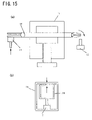
FIG. 15 is a view illustrating a constitution of an apparatus for measuring force transmission characteristics;
FIG. 16 is a view illustrating a measurement result of force transmission characteristics (yaw) of the OPT and the TOF;
FIG. 17 is a view illustrating a measurement result of force transmission characteristics (pitch) of the OPT and the TOF; and
FIG. 18 is a view illustrating a measurement result of force transmission characteristics (gripping) of the OPT and the TOF.
DETAILED DESCRIPTION OF THE INVENTION
In what follows, an embodiment of the present invention will be described. Although in the following there will be described a case where the present invention is applied to a multi-degree of freedom forceps for operations, it is applicable to manipulators for various applications in each of which it includes an operating part and a working part and the working part is operated in response to the operation of the operating part for various works.
Referring to FIG. 1 there are illustrated a schematic constitution of a forceps of the embodiment of the present invention and the degree of freedom in the forceps. And the degree of freedom of the forceps of the embodiment will be described.
In (a) of the same figure, designated at 1 is an operating part and 2 is a working part. The operating part 1 comprises first and second operating parts 1 a, 1 b, and the working part 2 comprises first and second working members 2 a, 2 b.
The operating part 1 and the working part 2 are coupled with a link mechanism 3 described later, and the first and second working members 2 a, 2 b of the working part 2 can be moved in response to the operation of the operating part 1 by controlling the first and second operating members 1 a, 1 b with a hand for example.
It is herein assumed that an axial direction of the link mechanism 3 provided between the operating part 1 and the working part 2 is X-axis and directions perpendicular to X-axis are Y-axis and Z-axis. When the operating part 1 is rotated around Y-axis as shown by an arrow A in the same figure, a movement of the operating part 1 is transmitted to the working part 2 via the link mechanism 3, and the working part 2 is also rotated in the direction of the arrow A in the same figure.
Further, when the operating part 1 is rotated around Z-axis as shown by an arrow B in the same figure, a movement of the operating part 1 is transmitted to the working part 2 via the link mechanism 3, and the working part 2 is also rotated as shown by the arrow B in the same figure.
Furthermore, when the first and second operating members 1 a, 1 b of the operating part 1 are opened and closed, the movement of the operating part 1 is transmitted to the working part 2 via the link mechanism 3, and the first and second working members 2 a, 2 b of the working part 2 are also opened and closed. It is usual in the forceps that the working part 2 is constructed in many cases as a gripping part for gripping an article. So, in the following, the opening and closing of the first and second working members 2 a, 2 b shall be referred to also as gripping, and the working part 2 as a gripping part.
In the following, the rotation around Y-axis shall be referred to as pitch as shown in FIG. 1( b), the rotation around Z-axis as yaw and the rotation around X-axis as roll.
As described above, the forceps of the present embodiment has additionally two-degree-of-freedom of rotation+freedom of gripping to the freedom possessed by conventional forceps. In contrast, when a conventional forceps with a tip end serving as only gripping is used for a low invasion operation, as shown in FIG. 1( c), a movement of the forceps is restricted by a hole, so that it has only four-degree-of-freedom, namely, thrust movement of the forceps along Z axis, rotation of the shaft around Z axis, and sway movement of the tip end in two directions along X or Y axis.
More specifically, the forceps of the present embodiment has the total of six-degree-of-freedom+gripping because it has the two-degree-of-freedom (pitch and yaw)+the freedom of gripping, as described above, additionally to the four-degree-of-freedom possessed by an ordinary forceps.
It is therefore possible for the tip end of the forceps to take an arbitrary position and attitude by making use of the forceps of the present embodiment.
It is general that a complicated work, particularly a stitching work is difficult in low invasion operation. However, provided that a forceps has a freedom at the tip end thereof, works are possible from an angle which is difficult to be taken by conventional forceps, and stitching works are also facilitated. The four-degree-of-freedom possessed by conventional forceps substantially corresponds to a movement of an arm of an operator, and the additional two-degree-of-freedom of the tip end of the forceps substantially corresponds to a wrist of an operator. It is therefore possible to also understand an effect of imparting greater freedom to the tip end of the forceps.
The forceps of the present embodiment directly controls the freedom of the tip end (working end) via the link mechanism 3, so that the force equal to that of the conventional forceps is transmitted to an operator. Further, the forceps of the present embodiment includes no electric circuit and actuator resulting in a simplified constitution, so that it is advantageous in costs and further, also in its introduction and operation it has no influence on other curing tools and diagnostic tools because they are not equipped with any electrical portion and so does not require any new external apparatus such as a power supply.
Referring now to FIG. 2 there is illustrated the entire constitution of the forceps of the embodiment of the present invention.
In the same figure, designated at 1 is a operating part composed of a first operating member 1 a and a second operating member 1 b, and 2 is a working part (gripper part) composed of a first working member 2 a and a second working member 2 b.
In between the operating part 1 and the working part 2 a link mechanism 3 is provided as described previously, and the link mechanism 3 comprises four driving rods 3 a to 3 d and first and second coupling members 41, 42 of the same structure provided at opposite ends of the driving rod.
The first and second working members 2 a, 2 b of the working part 2 move corresponding to the control of the first and second operating members 1 a, 1 b of the operating part 1 mediating the link mechanism 3.
The forceps of the present embodiment has the total seven degree-of-freedom (six-degree-of-freedom+gripping), i.e., the freedom of yaw, pitch, and gripping as described above, additionally to four-degree-of-freedom obtained by moving the whole forceps.
More specifically, once the first and second operating members 1 a, 1 b are opened and closed, the first working member 2 a and the second working member 2 b are opened and closed (gripping). Further, when yaw angles of the first and second operating members 1 a, 1 b are changed, yaw angles of the working members 2 a, 2 b are also correspondingly changed. Similarly, once pitch angles of the first and second operating members 1 a, 1 b are changed, pitch angles of the working members 2 a, 2 b are also correspondingly changed.
Designated at 5 in FIG. 2 is a fixing member described later, and the fixing member 5 consists of a coupling member 43 having the same structure as that of the coupling members 41, 42 and of fixing frame 51 for fixing the driving rods 3 a to 3 d such that the respective driving rods 3 a to 3 d are prevented from moving in a direction perpendicular to the axes of the driving rods 3 a to 3 d with respect to the casing (external frame 6 for covering the circumference of the driving rods) while allowing the movement of the driving rods 3 a to 3 d in the direction X.
Provided that the length of the forceps in the direction X is increased, the driving rods 3 a to 3 d are bent as force is applied thereto for example, so that there is the possibility that control force of the operating part 1 might be prevented from being transmitted correctly to the working part 2, and force applied to the working part 2 might be prevented from being correctly transmitted as inner force sense to the operating part 1.
It is possible to reduce an influence of the bending etc. of the driving rods 3 a to 3 d even if the length of the forceps in the direction X is increased by providing the fixing member 5 including the coupling member 43 in the way of the driving rods 3 a to 3 d as described above.
Instead of providing both coupling member 43 and the fixing frame 51, only the coupling member 43 may be provided at some points of the driving rods 3 a to 3 d. In this case, although it is possible to reduce an influence of bending etc. of the driving rods 3 a to 3 d, it is impossible to prevent the driving rods 3 a to 3 d from moving toward perpendicular to the axis of the external frame 6 due to the absence of the fixing frame 51.
Referring to FIG. 3, there is illustrated an exemplary constitution of the coupling member 42 provided on the side of the working part, with the same figure (a) that is a view of the working part 2 viewed from the direction of Z-axis and with (b) that is a cross sectional view taken along a line A-A of (a).
In the same figure (a), (b), designated at 2 a, 2 b are the first and second working members (there are partly shown the working members 2 a, 2 b in the same figure).
Designated at 3 a, 3 b are the driving rods. The driving rods 3 c, 3 d are hidden behind lower portions of the driving rods 3 a, 3 b and not seen in the same figure (a).
The first working member 2 a is coupled to the first movable member 4 b mounted on the central shaft 4 a, and the second working member 2 b is coupled to the second movable member 4 c mounted on a shaft member 4 r rotatable with respect to the central shaft 4 a.
On the opposite sides of the central shaft 4 a of the first movable member 4 b there are mounted rotatably a first rotary shaft 4 d parallel, in axial direction, to the central shaft 4 a and a second rotary shaft 4 e.
A first fixing member 4 m is mounted on the first rotary shaft 4 d, and a first driving rod support shaft 4 h perpendicular, in its axial direction, to the central shaft 4 a is mounted on the same. The driving rod 3 a is mounted rotatably on the first driving rod support shaft 4 h.
Further, on the second rotary shaft 4 e there are mounted a second fixing member 4 n and a second driving rod support shaft 4 i perpendicular, in axial direction, to the central shaft 4 a. The driving rod 3 b is mounted rotatably on the second driving rod support shaft 4 i.
Similarly, there are mounted rotatably on the opposite sides of the central shaft 4 a of the second movable member 4 c a third rotary shaft 4 f parallel, in axial direction, to the central shaft 4 a and a fourth rotary shaft 4 g.
On the third rotary shaft 4 f there are mounted a third fixing member 4 p and a third driving rod support shaft 4 j perpendicular, in axial direction, to the central shaft 4 a. The driving rod 3 c is mounted rotatably on the third driving rod support shaft 4 j.
Further, on the fourth rotary shaft 4 g there are mounted a fourth fixing member 4 q and a fourth driving rod support shaft 4 k perpendicular, in its axial direction, to the central shaft 4 a. The driving rod 3 d is mounted rotatably on the fourth driving rod support shaft 4 k.
The coupling member 42 has the constitution described above, wherein once the driving rod 3 a moves from the background of FIG. 3( b) to foreground and the driving rod 3 b moves from the foreground to the background, the first movable member 4 b rotates around the central shaft 4 a and the first working member 2 a rotates in the left direction of FIG. 3( a). Similarly, once the driving rod 3 d moves from the background of FIG. 3( b) toward the foreground and the driving rod 3 c moves from the foreground toward the background, the second movable member 4 c rotates around the central shaft 4 a and the second working member 2 b rotates in the right direction in the same figure. More specifically, once the first and second working members 2 a, 2 b are opened and the driving rods 3 a to 3 d move oppositely to the above description, the first and second working members 2 a, 2 b are closed.
Once the driving rods 3 a, 3 b move from the foreground of FIG. 3( b) toward the background and the driving rods 3 c, 3 d move from the background toward the foreground, the central shaft 4 a is inclined such that an upper side thereof becomes the background and a lower side thereof becomes foreground of FIG. 3( b). The first and second working members are inclined, and their tip end sides correspondingly move to the background in the same figure. Once the driving rods 3 a to 3 d move oppositely to the above description, their tip end sides move to the foreground in FIG. 3( a).
Additionally, once the driving rods 3 a, 3 c move from the foreground in FIG. 3( b) toward the background and the driving rods 3 b, 3 d move from the background toward the foreground, the first and second movable members 4 b, 4 c are rotated around the central shaft 4 a, and the first and second working members 2 a, 2 b are rotated in the right direction in FIG. 3( a). Once the driving rods 3 a to 3 d move oppositely to the above description, the first and second working members 2 a, 2 b are rotated in the left direction in FIG. 3( a).
Referring to FIG. 4 there is illustrated an exemplary constitution of the coupling member 41 provided on the side of the operating part with the same figure (a) that is a view illustrating the working part 2 viewed from the Z-axis direction and (b) a cross sectional view taken along a line A-A in (a).
The structure of the coupling member provided on the side of the operating part has the same constitution as the coupling member illustrated in FIG. 3 excepting the central shaft 4 a being long, and the same symbols shall be applied to the same portions.
In FIG. 4( a), designated at 1 a, 1 b are first and second operating members (in the same figure the operating members 1 a, 1 b are partly shown), and in the same figure the second operating member 1 b is hidden behind a lower side of the first control member 1 a.
In FIG. 4( a), (b), once the first operating member la is rotated to the right side, the first movable member 4 b is rotated around the central shaft 4 a to cause the driving rod 3 a to move from the background in FIG. 4( b) toward the foreground and the driving rod 3 b to move from the foreground toward the background. Hereby, the first working member 2 a on the side of the working part 2 is rotated to the left side as described previously.
Similarly, once the second operating member 1 b is rotated to the left side, the driving rod 3 d moves from the background in FIG. 3( b) to the foreground and the driving rod 3 c moves from the foreground to the background. Hereby, the second working member 2 b on the side of the working part 2 is rotated to the right side.
Further, once the first operating member 1 a and the second working member 1 b are turned to an upper side in FIG. 4( b), the central shaft 4 a is tilted to move the driving rods 3 a, 3 b from the foreground to the background and move the driving rods 3 c, 3 d from the background to the foreground of the same figure. Hereby, the tip ends of the first and second working members 2 a, 2 b on the side of the working part 2 are tilted to a lower side in FIG. 3( b).
Additionally, once the first operating member 1 a and the second working member 1 b are turned to the left side in FIG. 4( a), the first and second movable members 4 b, 4 c are turned around the central shaft to move the driving rods 3 a, 3 c from this side on the space to the interior and move the driving rods 3 b, 3 d from the background to the foreground in FIG. 4( b). Hereby, the tip ends of the first and second working members 2 a, 2 b on the side of the working part 2 are turned to the right as described previously.
Referring to FIGS. 5 to 7 there are illustrated schematic views of describing the operation of the forceps of the present embodiment where an aspect of the gripping and changes of the pitch angle and yaw angle when the operating part 1 is controlled are shown.
FIG. 5 is a schematic view illustrating the movements of the working members 2 a, 2 b of the working part 2 when the operating members 1 a, 1 b of the operating part 1 are turned respectively.
The same figure (a) and (b) are views each illustrating the movements of the operating member 1 a, the driving rods 3 a, 3 b on the upper side, and the working member 2 a. As illustrated in the same figure (a) and (b) once the operating member la is turned, the driving rods 3 a, 3 b move as indicated by an arrow in the same figure and the working member 2 a is turned as shown in the same figure. The same figure (c) is a view illustrating the movements of the operating member 1 b, the driving rods 3 c, 3 d on a lower side, and the working member 2 b. As illustrated in the same figure, once the operating member 1 b is turned, the driving rods 3 c, 3 d move as indicated by an arrow in the same figure and the working member 2 b is turned as shown in the same figure.
More specifically, the driving rods 3 a to 3 d move as shown in the same figure in response to opening and closing of the control members 1 a, 1 b, and in response to this the working members 2 a, 2 b are opened and closed.
It is hereby possible to grip an article with the working members 2 a, 2 b by controlling the operating members 1 a, 1 b.
The force acted on the working part 2 is transmitted to the operating members 2 a, 2 b via the driving rods 3 a to 3 d, and a worker can sense the force acted on the working part 2 as force sensation.
FIG. 6 is a schematic view illustrating the movement of the working part 2 when the pitch angle of the operating part 1 is changed.
Once the operating members 1 a, 1 b are turned as illustrated in the same figure to change the pitch angle, the driving rods 3 b, 3 d move as indicated by an arrow in the same figure, and so the working members 2 a, 2 b are turned as illustrated in the same figure to change the pitch angle. It is herein noticed that although the driving rods 3 a, 3 c are hidden behind the driving rods 3 b, 3 d and not seen in the same figure, the driving rod 3 a moves in the same direction as that of the driving rod 3 b and the driving rod 3 c as that of the driving rod 3 d.
FIG. 7 is a schematic view illustrating the movement of the working part 2 when the yaw angle of the operating part 1 is changed.
Once the operating members 1 a, 1 b are turned as illustrated in the same figure to change the yaw angle, the driving rods 3 a, 3 b move as shown by an arrow in the same figure, and so the working members 2 a, 2 b are turned as illustrated also in the same figure to change the pitch angle. It is herein noticed that although the driving rods 3 c, 3 d are hidden behind the driving rods 3 a, 3 b and not seen in the same figure, the driving rod 3 a moves in the same direction as that of the driving rod 3 c and the driving rod 3 c in the same direction as that of the driving rod 3 d.
Meanwhile, a forceps for use in the low invasion operation is configured into an elongated rod having a gripper part on the tip end of a shaft of about 300 mm ordinarily.
Provided that the forceps is increased in its length, the driving rods 3 a to 3 d are deflected for example when force is applied as described before, and so the operation force of the operating part 1 might be prevented from being correctly transmitted to the working part 2, and acted force on the working part 2 might be prevented from being correctly transmitted as force sensation.
In such a case, the coupling member 43 may be provided in the way of the driving rod as described previously. It is hereby possible to prolong the axial length of the forceps without substantially losing rigidity. It is further possible to prevent the coupling member 43 i.e. the driving rods 3 a to 3 d from moving with respect to the outer frame 6 by mounting the coupling member 43 on the fixing frame 51.
Referring to FIG. 8, there is illustrated an exemplary constitution of the fixing member composed of the coupling member 43 and the fixing frame 51, with (a) a view of the fixing frame 51 and the coupling member 43 seen from a Z-axis direction, and (b) a cross sectional view taken along A-A in (a).
In the same figure (b), the fixing frame 51 is mounted on the outer frame 6 via the shaft 5 a and is turnable around the shaft 5 a. The axial direction of the shaft 5 a is parallel to Y-axis in FIG. 1.
Further, the central shaft 4 a of the coupling member is attached to upper and lower frames of the fixing frame 51. For this, the coupling member 43 is turnable around the central shaft 4 a.
Although the structure of the coupling member 43 is basically the same as those illustrated in FIGS. 3, 4, the coupling member 43 does not include the operating members 1 a, 1 b and the working members 2 a, 2 b, and the coupling rods 3 a to 3 d are mounted turnably on the first to fourth driving rod support shafts 4 h to 4 k of the coupling member 43, and further the driving rods 3 a to 3 d are extended to before and behind the coupling member 43 as illustrated in FIG. 8( a).
The movement of the coupling member 43 is the same as that illustrated in FIG. 4; once the driving rod 3 a moves from the background in FIG. 8( b) and the driving rod 3 b moves from the foreground to the background, the first movable member 4 b is turned around the central shaft 4 a. Similarly, once the driving rod 3 d moves from the background in FIG. 8( b) toward the foreground and the driving rod 3 c moves from the foreground toward the background, the second movable member 4 c is turned around the central shaft 4 a. Provided that the driving rods 3 a to 3 d move oppositely to the above situation, the first and second movable members 4 b, 4 c are turned oppositely.
Further, once the driving rods 3 a, 3 b move from the foreground in FIG. 8( b) toward the background and the driving rods 3 c, 3 d move from the background toward the foreground, the central shaft 4 a, in FIG. 8( b), is tilted such that an upper side thereof becomes the background and a lower side thereof becomes the foreground, and the fixing frame 51 is also likewise tilted. Once the driving rods 3 a to 3 d move oppositely to the above description, the central shaft 4 a is tilted such that an upper side thereof becomes the foreground and a lower side thereof becomes the background, and the fixing frame 51 is also likewise tilted.
Additionally, once the driving rods 3 a, 3 c move from the foreground in FIG. 8( b) toward the background and the driving rods 3 b, 3 d move from the background toward the foreground, the first and second movable members 4 b, 4 c are turned around the central shaft 4 a. Once the driving rods 3 a to 3 d move oppositely to the above situation, the first and second movable members 4 b, 4 c are turned oppositely.
Herein, only the coupling member 43 may be provided without providing the fixing frame 51 as described previously. The situation is the same as the above description excepting a fact that the central shaft 4 a of the coupling member 43 is not mounted on the fixing frame 51.
And now, endoscopic operation sometimes suffers from a problem of gripping force. When there is a need of increasing gripping force at the working part of the forceps, it is possible to realize an increase of the gripping force by mounting a link mechanism on the tip ends of the first and second working members.
FIG. 9( a) is a view illustrating a schematic constitution of the link mechanism. An arm 2 c is mounted on the tip ends of the first and second working members 2 a, 2 b of the working part, and “L”-shaped third and fourth working members 2 d, 2 e are mounted on the arm 2 c.
The first and second working members 2 a, 2 b are turned around a rotary shaft 2 f, and the upper and lower arms 2 cs are coupled turnably with the first and second working members 2 a, 2 b. Further, the third and fourth working members 2 d, 2 e are mounted turnably around a rotary shaft 2 g parallel, in its axial direction, to the rotary shaft 2 f, and each of the arms 2 c is turnably coupled with one ends of the third and fourth working members 2 d, 2 e. The other ends of the third and fourth working members 2 d, 2 e are the gripping part for gripping an article.
FIG. 9( b) illustrates a mechanism composed of the first and third working members of the link mechanism; the first and second working members 2 a, 2 b are equal to each other in length, likewise, upper and lower arms 2 cs, third and fourth working members 2 d, 2 e are all equal to each other in their lengths. The length of the first working member 2 a (2 b) is assumed to be a; the length of the arm 2 cb; the length of the third working member 2 d (2 e) from the rotary shaft 2 g to the coupling part of the arm 2 cc; a distance between the rotary shaft 2 f of the working member 2 a and the rotary shaft 2 g of the third working member 2 dh; an angle formed between a line connecting between the rotary shaft 2 f and the rotary shaft 2 g and the first working member 2 a θ; and an angle formed between a line connecting the rotary shaft 2 f and the rotary shaft 2 g and a line connecting the rotary shaft 2 g of the working member 2 d (2 e) and its tip end φ, which satisfy the following relations:
d 2 =a 2 +h 2−2ah cos θ
π/2−φ=φ1+φ2
a 2 =d 2 +h 2−2dh cos φ1
b 2 =d 2 +c 2−2dc cos φ2
FIG. 10 is a view illustrating a relationship between the foregoing φand reduction gear ratios of the third and fourth working members 2 d, 2 e with respect to the first and second working parts 2 a, 2 b. It is possible to reduce the speed of the third and fourth working members 2 d, 2 e as φ is more reduced as illustrated in FIG. 10 and hence to increase the force applied to the third and fourth working members 2 d, 2 e by setting the length b of the arm 2 c and the distance h between the rotary shaft 2 f of the working member 2 a and the rotary shaft 2 g of the working member 2 d to satisfy a relation: b<h and making the shape of a rectangle formed by the length b and the distance h a trapezoid as illustrated in FIG. 9( b).
For this, it is possible to increase the gripping force when a needle or the like is gripped at the tip end of the forceps for example and improve operationability. Additionally, it is possible to shift a rotary article (rotary shaft 2 f) and an axis of gripping (rotary shaft 2 g) and hence improve the operationability by providing the link mechanism. Furthermore, it is also possible to reduce an influence of friction because the force can be increased.
The forceps of the present embodiment, as described above, transmits an input to the operating part 1 to the working part 2 (the tip end of the forceps) through the four driving rods 3 a to 3 d, and the forceps of the present embodiment has the following features:
(1) All degrees of freedom of the three-degree-of-freedom can be realized by only the link mechanism composed of the four driving rods. Manipulators of a parallel link structure are ones that consider only a position of a tip end thereof and an attitude thereof, and many of them incorporate a terminal effector such as a gripper and a drill at the tip end thereof and realize the freedom of the gripper not by a link but by wires and springs. So, when a forceps is directly operated, an operator feels elasticity of the spring and friction of the wire, which is not preferable. Also, they have the difficulty that any material is worn away by the friction of the wire.
Against this, the forceps of the present embodiment employs the link mechanism using the four driving rods 3 a to 3 d, so that the foregoing difficulty does not happen.
(2) The two-degree-of-freedom of rotation and the shaft axis of the forceps intersect at one point. Consequently, the turning around the roll shaft at the tip end of the forceps is enabled by the cooperation of the turning around the shaft axis and the pitch. This ensures excellent operationability and complicated control.
(3) When the article angle of the tip end of the forceps is changed, there is no chance of portions of the forceps other than the tip end being deformed such as other portions of forceps being protruded. Accordingly, when the forceps is applied to a low invasion operation for example, there is no chance of the shape of the forceps being changed outside the scope of an endoscope and hence there is no possibility of any organ or the like being caught up by the forceps.
Table 1 illustrates differences among the forceps of the present invention, the forcipes of the references 2 and 3, and the prior art forceps (having four-degree-of-freedom+gripping).
| |
TABLE 1 |
| |
|
| |
|
|
Forceps of the |
|
| |
|
|
present |
Conventional |
| |
Ref. 2 |
Ref. 3 |
invention | Forceps |
| |
|
| |
| |
6 + 1 |
6 + 1 |
6 + 1 |
4 + 1 |
| of |
(gripping) |
(gripping) |
(gripping) |
(gripping) |
| Freedom |
| Force |
Nil |
Medium |
High |
High |
| Sensation |
| Cost |
Expensive |
Relative |
Relatively |
Inexpensive |
| |
(Some |
Expensive |
Inexpensive |
(some |
| |
hundred |
(Some |
|
hundred |
| |
millions |
million |
|
thousand |
| |
yen) |
yen) |
|
yen) |
| Advantageous |
Low |
Medium |
High |
High |
| in |
| Introduction & |
| Operation |
| |
As understood from Table 1, the forceps of the present invention enjoys the following effects: it is possible to transmit force sensation inexpensively while having the same degree of freedom as those of the forceps disclosed in reference 2 and reference 3; it is inexpensive and is advantageous in the aspect of the introduction and operation thereof; and further it has higher degree of freedom and greater controllability than the prior art forceps.
Table 2 illustrates features of the forceps of the present invention and the forceps of references 2 to 6 from the aspect of the operationability of the forceps.
| |
TABLE 2 |
| |
|
| |
|
|
|
|
Forceps |
| |
|
|
|
|
of the |
| |
|
|
|
Refs |
present |
| |
Ref. 2 |
Ref. 3 |
Ref. 4 |
5&6 |
invention |
| |
|
| |
| Do rotary shafts of |
No |
Yes |
No |
Yes |
Yes |
| two-degree-of-freedom |
| at the tip end |
| intersect? |
| Free from influence of |
No |
No |
Yes |
Partially |
Yes |
| static friction by |
|
|
|
Yes* |
| wire? |
| Without Protruded |
Yes |
Yes |
No |
Yes |
Yes |
| portion upon bending? |
| Rigidity of force |
No |
No |
Yes |
Partially |
Yes |
| transmission method |
|
|
|
Yes* |
| |
| *on the condition that only gripping utilizes wire. |
As shown in Table 2, the forceps of the present invention has higher operationability because rotary axes of the two-degree-of-freedom of rotation at the tip end of the forceps of the present invention intersect and it is less influenced by static friction compared with those utilizing wires because whole freedom is constituted by a link.
Additionally, there is no possibility that any other article than the aimed is caught up by the forceps because no bulged part could be occurred to the link mechanism at the time of bending of the tip end of the forceps, and the forceps has a fast force response because it adopts a link mechanism with higher rigidity than that of a wire.
Moreover, the forceps of the present embodiment is successful to pass through a cylinder of 12 mm. This is a size with which we can pass through an existing trocars, and which can be said as a practical size. For a movable range on design the change of the yaw angle is ±75°, the change of the pitch angle is ±60°, gripping ranges from 0° to 30°, so that it is possible to grip and lift up a weight of 410 grams.
It is generally said that if a forceps can generate force of about 4N, then it is applicable to low invasion operations. The developed forceps has enough rigidity against generated force necessary for a work in an abdominal cavity.
For checking the availability of the forceps of the present embodiment a correspondence of freedoms of the operating part of the forceps and of the tip end of the forceps was measured, and it was measured how much the force applied to the tip end of the forceps is transmitted to the operating part.
For checking a correspondence between movements of the operating part and of the tip end of the forceps, the operating part and the tip end of the forceps were simultaneously photographed using a home digital video camera to check the correspondence.
As shown in FIG. 11, the forceps 10 was photographed with video cameras 12, 13 in its state where it was fixed to a vise 11 at its shaft part.
A marker is detected by template matching from a photographed image, and attitudes of the tip and of the forceps and of the control part are calculated from coordinates of the maker. At that time, the forceps 10 is assumed to move on a two-dimensional plane, and a geometrical relation of the cameras 12, 13 is assumed to be parallel projection. A frame rate is 30.0 fps with a resolution of 740×480. Synchronization was taken by simultaneously lighting LEDS in two images,
FIGS. 12 to 14 illustrate respective measurement results of the yaw, pitch, and gripping. The abscissa in the same figures is time(s) and the ordinate is angle (°), which indicate the movements of the operating part and the tip end of the forceps (working part). As illustrated in the same figures it is understood that for the yaw, pitch, and gripping the movement of the tip end of the forceps substantially corresponds to that of the tip end of the forceps.
However, hysteresis characteristics by an influence of backlash are found, causing a deviation of 15° at the maximum.
As shown in FIGS. 12 and 13, even if deviations between the operating part and the tip end of the forceps are increased at upper end peaks of waves and at lower end peaks of the same, those peaks for the tip end of the forceps have not been changed. This is considered that the reason is because an actual movable range is narrower than the designed one,
Then, force transmission performance was measured. As shown in FIG. 15( a) force transmitted from the tip end of the forceps or force transmitted from the operating part to the operating part or to the tip end of the forceps was measured by operating the operating part while measuring force of the operating part by mounting a force sensor 14 on the operating part, and by making the tip end of the forceps contact with a force sensor 15.
This experiment was also implemented in the state where the forceps 10 was fixed to a vise 11 as a shaft part thereof. When the gripping force is measured, the measurement was implemented by mounting two square pipes 16 a, 16 b on a force sensor 17 as illustrated in FIG. 15( b).
FIGS. 16 to 18 illustrate respective measurement results of the yaw, pitch, and gripping. In the same figures, the abscissa is time (s) and the ordinate is force (N) that indicates force acting on the operating part and on the tip end of the forceps (working part).
It is understood from the same figure that generated force at the tip end of the forceps follows up applied force to the operating part. However, it can be read out that the generated force at the tip end of the forceps is retarded with respect to the applied force to the operating part. The deviation of the forces at the operating part and the tip end of the forceps was 1N at the maximum. Particularly, it can be read that the degree of freedom of the yaw angle is severely influenced by friction and backlash.