US7694591B2 - Method and apparatus for evaluating a dosing operation - Google Patents
Method and apparatus for evaluating a dosing operation Download PDFInfo
- Publication number
- US7694591B2 US7694591B2 US11/642,116 US64211606A US7694591B2 US 7694591 B2 US7694591 B2 US 7694591B2 US 64211606 A US64211606 A US 64211606A US 7694591 B2 US7694591 B2 US 7694591B2
- Authority
- US
- United States
- Prior art keywords
- pressure
- pump
- dosing
- temperature
- time
- Prior art date
- Legal status (The legal status is an assumption and is not a legal conclusion. Google has not performed a legal analysis and makes no representation as to the accuracy of the status listed.)
- Active - Reinstated, expires
Links
Images


Classifications
-
- G—PHYSICS
- G01—MEASURING; TESTING
- G01F—MEASURING VOLUME, VOLUME FLOW, MASS FLOW OR LIQUID LEVEL; METERING BY VOLUME
- G01F11/00—Apparatus requiring external operation adapted at each repeated and identical operation to measure and separate a predetermined volume of fluid or fluent solid material from a supply or container, without regard to weight, and to deliver it
- G01F11/02—Apparatus requiring external operation adapted at each repeated and identical operation to measure and separate a predetermined volume of fluid or fluent solid material from a supply or container, without regard to weight, and to deliver it with measuring chambers which expand or contract during measurement
- G01F11/021—Apparatus requiring external operation adapted at each repeated and identical operation to measure and separate a predetermined volume of fluid or fluent solid material from a supply or container, without regard to weight, and to deliver it with measuring chambers which expand or contract during measurement of the piston type
- G01F11/029—Apparatus requiring external operation adapted at each repeated and identical operation to measure and separate a predetermined volume of fluid or fluent solid material from a supply or container, without regard to weight, and to deliver it with measuring chambers which expand or contract during measurement of the piston type provided with electric controlling means
-
- B—PERFORMING OPERATIONS; TRANSPORTING
- B01—PHYSICAL OR CHEMICAL PROCESSES OR APPARATUS IN GENERAL
- B01L—CHEMICAL OR PHYSICAL LABORATORY APPARATUS FOR GENERAL USE
- B01L3/00—Containers or dishes for laboratory use, e.g. laboratory glassware; Droppers
- B01L3/02—Burettes; Pipettes
- B01L3/021—Pipettes, i.e. with only one conduit for withdrawing and redistributing liquids
- B01L3/0217—Pipettes, i.e. with only one conduit for withdrawing and redistributing liquids of the plunger pump type
-
- G—PHYSICS
- G01—MEASURING; TESTING
- G01N—INVESTIGATING OR ANALYSING MATERIALS BY DETERMINING THEIR CHEMICAL OR PHYSICAL PROPERTIES
- G01N35/00—Automatic analysis not limited to methods or materials provided for in any single one of groups G01N1/00 - G01N33/00; Handling materials therefor
- G01N35/10—Devices for transferring samples or any liquids to, in, or from, the analysis apparatus, e.g. suction devices, injection devices
- G01N35/1009—Characterised by arrangements for controlling the aspiration or dispense of liquids
-
- B—PERFORMING OPERATIONS; TRANSPORTING
- B01—PHYSICAL OR CHEMICAL PROCESSES OR APPARATUS IN GENERAL
- B01L—CHEMICAL OR PHYSICAL LABORATORY APPARATUS FOR GENERAL USE
- B01L2200/00—Solutions for specific problems relating to chemical or physical laboratory apparatus
- B01L2200/14—Process control and prevention of errors
- B01L2200/143—Quality control, feedback systems
- B01L2200/146—Employing pressure sensors
-
- B—PERFORMING OPERATIONS; TRANSPORTING
- B01—PHYSICAL OR CHEMICAL PROCESSES OR APPARATUS IN GENERAL
- B01L—CHEMICAL OR PHYSICAL LABORATORY APPARATUS FOR GENERAL USE
- B01L2200/00—Solutions for specific problems relating to chemical or physical laboratory apparatus
- B01L2200/14—Process control and prevention of errors
- B01L2200/148—Specific details about calibrations
-
- G—PHYSICS
- G01—MEASURING; TESTING
- G01N—INVESTIGATING OR ANALYSING MATERIALS BY DETERMINING THEIR CHEMICAL OR PHYSICAL PROPERTIES
- G01N35/00—Automatic analysis not limited to methods or materials provided for in any single one of groups G01N1/00 - G01N33/00; Handling materials therefor
- G01N35/10—Devices for transferring samples or any liquids to, in, or from, the analysis apparatus, e.g. suction devices, injection devices
- G01N35/1009—Characterised by arrangements for controlling the aspiration or dispense of liquids
- G01N35/1016—Control of the volume dispensed or introduced
- G01N2035/1018—Detecting inhomogeneities, e.g. foam, bubbles, clots
Definitions
- the invention relates to a method and an apparatus for evaluating a dosing operation, carried out by means of a dosing pump, for dosing a liquid medium, more especially for evaluating an aspirating and/or dispensing operation during the pipetting process, according to the preamble of claims 1 and 18 .
- Dosing operations for dosing liquids are often a constituent part of mixing or analyzing methods, wherein exact doses of liquids are taken from quantities of liquid and, for example, mixed together. Such operations are the order of the day in chemical, pharmaceutical, medicinal and human biological methods, but they may also occur in other technical fields. Unidentified inaccurate liquid dosages can thus lead to results which are hazardous or even dangerous for the health of living beings, more especially human beings, when the use of such dosing operations in the pharmaceuticals sector alone is considered. On the other hand, unnecessary waste dosages are to be avoided in order not to waste unnecessarily valuable and sometimes only limited available substances. In this respect, there is a need to be able to evaluate liquid dosing operations as early as possible with the greatest possible reliability for their accuracy.
- the transfer of specific liquid volumes begins with an aspiration operation, wherein the liquid to be transferred is drawn, for example, into a disposable pipette or tip.
- This aspiration or intake can be disturbed by various factors, for example air bubbles in the vessel, inhomogeneity of the liquid caused by coaglutinates, technical errors in the system, such as leakages, etc. All of these factors lead to a deviation of the actual drawn-in volume from the desired drawn-in volume.
- the detection of faulty aspiration operations but also dispense operations is essential for the reliability of such apparatuses.
- a desired development of a state variable such as, for example, the pressure or the temperature of the medium which is drawn-in and is to be metered, for example over time is checked.
- a method and an apparatus are known for evaluating a liquid dosing operation, wherein a continuous development, with respect to time, of a state variable during a dosing operation is compared with a predetermined state variable desired value range over the substantially total time of a dosing operation. In dependence on this desired/actual comparison, an evaluation result is issued as to how far the liquid dosing operation was successful or not.
- the beginning of the liquid dosing operation or machine state variables such as the position of a piston in the vessel, can be detected. A correlation between the machine state and the measured state variable is not established. In consequence, error regions in fact result there from the machine state, but not other desired values. In consequence, the test mechanism always remains identical, since only the desired values are exchanged.
- EP 981 048 B1 calculates as the desired value a pressure integral via a part of a pressure profile, produced with a reference liquid, and compares this desired value subsequently with an appropriate actual pressure integral. From EP 1 036 335 A, certain conditions are known which, for the monitoring based on the pressure determination over time, define limit values for the initial rise in vacuum, the time until the initial fall in vacuum, the pressure before the rise, the pressure after the fall and the pressure difference. Also, a monitoring, based solely on a pressure monitoring, is effected in the patents U.S. Pat. No. 6,119,533 A, U.S. Pat. Nos. 6,121,049 A and 6,158,269 A, or as a fault monitoring means dependent on the final pressure according to EP 682 258 B1.
- a fault monitoring means during aspiration through pressure monitoring during the immersion process up to a constant pressure is known from U.S. Pat. No. 5,463,895 A; a foam monitoring means with a pressure limit value is known from U.S. Pat. No. 5,488,854 A; and a monitoring means for monitoring coagulation clots is known from U.S. Pat. No. 5,540,081 A using a plurality of discrimination circuits for the pressure monitoring of various regions.
- a leakage test is known through monitoring for abrupt pressure changes during the dispense operation.
- the pump internal pressure is checked preferably once daily, when the aspiration process is stopped, to see whether and how quickly it drops towards air pressure. In consequence, the pressure after aspiration is tested in isolation, but not the entire course of the pump activity.
- the invention makes available an alternative possibility which permits a reliable evaluation of liquid dosing operations.
- the development of the pressure or of the temperature of the gas is detected in the vessel, into which the medium is dosed, with a prescribed course of the pump output or pump rate of the dosing pump.
- This means that the pressure or the temperature of the medium is correlated with the pump rate or pump output, in order to generate thereby conditions which permit an evaluation of the dosing operation as correct, in need of correction or faulty.
- the system is not only based on the pressure or the temperature, but also on the pump rate or pump output of the dosing pump, the system works very reliably.
- the system can be adapted to various existing apparatuses, through the input of few limit values and/or determination variables of the dosing pump.
- FIG. 1 is a schematic view of a dosing apparatus
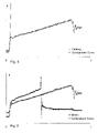
- FIG. 2 illustrates a typical pressure development of an aspiration process, superimposed with the rate development of the pump
- FIG. 3 illustrates a typical pressure development over time during an aspiration of air bubbles/foam relative to a comparison curve
- FIG. 4 illustrates a typical pressure development over time in the event of a blockage relative to a comparison curve
- FIG. 5 illustrates a typical pressure development with an inadequate readjustment of the vessel relative to a comparison curve.
- FIG. 6 illustrates a typical pressure development a dispense process, superimposed with the rate development of the pump
- the apparatus illustrated schematically in FIG. 1 is used for dosing a liquid medium into a vessel 20 , filled at least partially with a gas, preferably with air.
- the vessel 20 may be a disposable pipette.
- the dosing operation is more especially an aspirating and/or a dispensing operation, such as is used in a pipetting apparatus or system.
- Such dosing apparatuses are used for dosing preferably liquid media in chemical, pharmaceutical, medicinal and human biological methods and the like. It is significant, in this respect, to detect accurately the quantities to be metered and to recognize such, more especially, if a dosing operation ever fails for any reason.
- the pressure p of the gas 10 present in the vessel 20 is detected via a sensor 21 at least periodically during the dosing operation, to produce a pressure development or course.
- the values thus determined are given to the control unit 23 , which includes a data storage unit 25 for the determined values on the one hand and, on the other hand, a data processing unit 27 .
- a reduced pressure is produced in the vessel 20 , by means of a system medium 24 , which may be air or a liquid, in order to aspire liquid, or respectively a pressure is produced in order to dispense liquid again.
- the control unit communicates with the dosing pump 22 via a control line.
- the pump rate or pump output is prescribed at the control unit 23 .
- control unit 23 or the data processing unit respectively calculates evaluation criteria, which permit an evaluation as to whether the dosing operation is successful or not.
- the evaluation result can be issued on a read-out unit 26 , for which any desirable apparatus is considered, which permits an interface with another apparatus or with the person by means of an acoustic or visual signal. Equally, a display on a display screen is possible.
- a typical dosing operation basically shows the pressure curve illustrated in FIG. 2 .
- the pressure is at ambient pressure up to the point in time t 1 when the tip of the vessel dips into the liquid.
- the pressure during the aspiration process and during the dispense process is referenced to this ambient pressure or—in better words—to the pressure that exists prior to the pump action.
- the starting of the dosing pump 22 then leads to a pressure increase.
- the quantity of gas present in the vessel 20 is separated from the ambient air, and the pressure rises with a further pumping movement of the dosing pump 22 , the suction pressure being added as the pressure at the tip of the disposable pipette.
- the dosing pump conducts its output, from a certain point in time, back along a retarding ramp 30 until the stoppage 32 of the dosing pump, in order to meter as accurately as possible the desired quantity.
- the pressure initially drops, because the suction pressure at the tip of the pipette is no longer present, until it levels-out towards the end of the dosing operation to a constant range, which is dependent on the liquid column in the vessel.
- the retarding ramp 30 there is nevertheless a further increase in the pressure p, since a slowing-down of the pressure can still be set in dependence on the viscosity of the liquid to be metered.
- the pressure profile over the time t illustrated in FIG. 2 in the lower region, can extend in a considerably flatter manner, so that, for example, sometimes no fall in pressure can be set after the beginning of the retarding ramp.
- a development of the pressure p with respect to time of a gas 10 present in the vessel 20 is initially detected at least periodically during the dosing operation.
- This development with respect to time (illustrated as the lower curve in FIG. 2 ) is compared with a desired value development of at least one pump rate or pump output of the dosing pump 22 , defining the dosing operation.
- the comparison result then leads to the evaluation criterion, whereby a plurality of error conditions are used for the evaluation of the dosing operation, which conditions consider the pressure development in a time window ⁇ t after a prescribed change in the defining pump rate or pump output.
- These values are present or respectively are prescribed as control variables, and are, in consequence, known to the control unit 23 .
- the rate development 35 of the pump plunger of the dosing pump 22 is illustrated. These values are correlated with one another, in order to produce thereby evaluation conditions, after a desired/actual comparison, and to make available an evaluation result of the dosing operation.
- a desired value range or desired value development respectively is produced, which is multi-dimensional.
- a desired value window is setup in which both the pump state variables and the pressure or the temperature of the gas are to move, so that a dosing operation can be evaluated as successful.
- the dosing operation is evaluated as faulty or in need of correction when it is determined that the detected development, with respect to time, of the pressure p or of the temperature lies outside a desired value range, at least in sections, with a prescribed pump rate or prescribed pump output.
- the obtained pressure or temperature signal in consequence, can be evaluated in conjunction with the development of the pump state variable as follows, each of the following error conditions also being able to be checked on its own as an exclusion criterion, but a plurality of error conditions are checked:
- the delay between the starting 31 of the dosing pump and the increase t 1 in the pressure p or the change in the temperature T is determined and may not exceed a limit value ⁇ t 1 . If this limit value is exceeded, an error message is produced.
- the pressure increase or the temperature change is usually determined by calculating the first deviation of the pressure signal or of the temperature signal respectively, while the starting time of the dosing pump 22 is known to the control system. If, in the case of an error, only air is drawn-in, no pressure increase and no temperature change respectively can be determined. Through the vertical readjustment of the pipette, the contact with the fluid can then initially still occur. In this case, the pressure increase or the temperature change respectively is delayed. If there is no pressure increase or no temperature change respectively, an error condition exists. Usually, the vertical readjustment of the vessel 20 is forcibly controlled by a stepping motor, but basically even a regulated readjustment can be effected.
- the pressure p must constantly rise or respectively the temperature must constantly change.
- the development can be defined as monotonically ascending when each scanning value is greater than the preceding value. This is not the case, for example, in FIG. 3 , since the aspiration of air bubbles leads to characteristic discontinuities in the pressure curve, since the flow resistance during the aspiration of air is much smaller than during the aspiration of liquid. More especially, in the case of insufficient vertical readjustment of the pipette, that is to say of the vessel 20 , the contact with the liquid can be lost, whereby air is drawn-in. Even in this case, the constant increase in the pressure does not exist, as for example the sketch in FIG. 5 shows.
- the pressure should be monotonically descending after expiry of the time ⁇ t 2 after the beginning t 2 of the retarding ramp 30 of the dosing pump 22 until the stoppage 32 of the dosing pump 22 , for which purpose the calculation of the first deviation is suitable.
- each pressure increase is detected until the switching-off of the dosing pump.
- a condition can be defined, in consequence, via the length of the aspiration operation, which cannot be defined solely by consideration of the pressure development. If there is too long a period until the fall in pressure, the metered quantity is to be rejected.
- the pressure should move in a specific tolerance range 33 .
- a maximum pressure p_max should not be exceeded.
- Large coaglutinates, high-viscous liquids or a blocked intake opening of the pipette, as for example in FIG. 4 produce an excessive pressure increase and can be detected by a limit value at this time.
- the pressure should be greater than a minimum limit value p_min.
- a partial drawing-in of air, air bubbles or a leak in the pipette result in too low a pressure.
- the characteristic point of the starting of the retarding ramp 30 is selected as the time for checking, since a large part of the volume here is already drawn-in, and the flow resistance is consequently at its maximum.
- the delay ⁇ t const between the end 32 of the pump movement and achieving a constant pressure or a constant temperature is defined, and should not exceed a limit value. Liquids with too high a viscosity or a partial blockage of the intake opening of the vessel 20 retard the fall in pressure or the achievement of a constant temperature at the end of the intake operation, and can be recognized by exceeding a limit value with respect to time.
- the value existing in the case of constant pressure or constant temperature at the end of the dosing operation, must lie within a tolerance range 34 .
- the pressure or the temperature is still only dependent on the static value of the liquid column.
- the value is a parameter for the drawn-in volume. In consequence, the usability of the sample can be evaluated.
- An alternative to prescribing the pump rate or output may reside in prescribing another variable such as, for example, the current consumption of the pump or the volumetric flow of the medium, and to control the pump in dependence thereon. This would have the consequence that that variable must be prescribed, and the pump development must be measured parallel to the pressure.
- the detection of the pressure p of the gas in the vessel is effected via a by-pass duct 28 , communicating with the gas in the vessel 20 and being provided on the holder 11 of the vessel.
- the by-pass duct permits an immediate measurement of pressure changes in the vessel, without having to refer to measurements of changes in the medium.
- This by-pass duct is not, therefore, a mere T-shaped part—as is usual in prior art—wherein, because of the direct branching-off from the intake duct 19 , the medium in the vessel and pump must be identical, so that the T-shaped part can be used to connect with the pressure sensor.
- the medium between pump 22 and vessel 20 can be different from that in the by-pass duct, e.g.
- the medium in the pump may be a system liquid.
- the medium in the vessel 20 should be air, because the vessel in the form of a single-use pipette is replaced for each transfer. Only this type of measuring duct renders possible the measurement of the pressure in the vessel with the simultaneous use of system liquid. By this means, the pressure can be measured independently of the medium via which the dosing pump 22 produces the reduced pressure in the vessel 20 .
- a liquid medium can be used in the same way as a gaseous medium for this purpose, and such increases the possible uses of the apparatus.
- the seven conditions mentioned relate to an aspirating operation, but they may be transferred to the dispensing operation illustrated in FIG. 6 with reversed signs.
- the reference numerals in FIG. 6 are identical to those in FIG. 2 .
- the monitoring of a pressure rise during the aspirating operation corresponds to a monitoring of a pressure fall during in the case of dispensing.
- the rate development 35 of the pump plunger of the dosing pump 22 is illustrated. Shown are starting 31 , retarding ramp 30 and stoppage 32 of the dosing pump 22 .
- FIG. 6 shows a delay between the starting 31 of the dosing pump and the drop t 1 in the pressure p, which delay may not exceed a limit value ⁇ t 1 . If this limit value is exceeded, an error message is produced. Additionally, between the increase in the pressure at time t 1 and at the beginning t 2 of the retarding ramp 30 of the dosing pump 22 , the pressure p must constantly fall. The development can be defined as monotonically falling when each scanning value is smaller than the preceding value. This is not the case, for example, with air bubbles and leads to an error condition.
- the pressure should be monotonically ascending after expiry of the time ⁇ t 2 after the beginning t 2 of the retarding ramp 30 of the dosing pump 22 until the stoppage 32 of the dosing pump 22 , for which purpose the calculation of the first deviation is suitable.
- each pressure increase is detected until the switching-off of the dosing pump.
- the time ⁇ t 2 between the beginning t 2 of the retarding ramp 30 of the dosing pump 22 until the actual rise in the pressure p must not exceed a limit value.
- a condition can be defined, in consequence, via the length of the aspiration operation.
- the pressure should move in a specific tolerance range 33 .
- a maximum pressure p_max should not be exceeded.
- the pressure should be greater than a minimum limit value p_min.
- the delay ⁇ t const between the end 32 of the pump movement and achieving a constant pressure is defined, and should not exceed a limit value. Liquids with too high a viscosity or a partial blockage of the intake opening of the vessel 20 retard the rise in pressure at the end of the intake operation, and can be recognized by exceeding a limit value with respect to time. If ⁇ t const , is not exceeded, the value, existing in the case of constant pressure at the end of the dispense operation, must lie within a tolerance range 34 . At the end of the dispense operation, the pressure is still only dependent on the static value of the liquid column.
- the pressure is referenced to the ambient pressure or—in better words to the pressure existing prior to the pump action during the aspirating operation as well as during the dispensing operation.
- all pressure measuring values are preferably referenced to the pressure prior to the pump action. In dispensing the liquid, however, the pressure has not to fall back to this reference pressure, especially if only a part of the liquid is dispensed.
- the temperature may be used and evaluated instead of the pressure.
- a liquid aspirating operation or liquid dispensing operation is usually a fast process, at least fast compared with a temperature compensation between the gas enclosed in the vessel and its environment. Therefore, the following equations known in physics for adiabatic change of state of ideal gases can approximately be used. These equations show the interrelation between volume, pressure and temperature.
- the values pressure p 1 , volume V 1 , temperature T 1 describe the initial state before the aspiration process.
- the values pressure P 2 , volume V 2 , temperature T 2 describe any arbitrary later point in time after a change of state.
- Value x is a constant specific for a certain gas. In the case of air 1,402.
- Equation (1) shows, how the pressure changes as a consequence thereof.
- the temperature changes as can be seen in equation (2).
- This equation shows that the pressure development is associated with a temperature development comprising the same qualitative characteristics. Rising pressure corresponds to rising temperature and vice versa. Therefore, the detection and evaluation of the temperature development is equally adapted as the pressure measurement and leads to a graph of temperature over time which is essentially analogue to the figures showing the pressure development.
- a preferred purpose of use is a pipetting system or apparatus which carries out an appropriate aspirating and/or dispensing operation during the pipetting process.
Abstract
Description
Claims (31)
Applications Claiming Priority (3)
| Application Number | Priority Date | Filing Date | Title |
|---|---|---|---|
| DE102005060862A DE102005060862B3 (en) | 2005-12-20 | 2005-12-20 | Assessing dosing performance of pipette connected to metering pump comprises determining pressure-time plot and comparing it with target plot of pump speed or power |
| DE102005060862 | 2005-12-20 | ||
| DE102005060862.0 | 2005-12-20 |
Publications (2)
| Publication Number | Publication Date |
|---|---|
| US20070177986A1 US20070177986A1 (en) | 2007-08-02 |
| US7694591B2 true US7694591B2 (en) | 2010-04-13 |
Family
ID=38109101
Family Applications (1)
| Application Number | Title | Priority Date | Filing Date |
|---|---|---|---|
| US11/642,116 Active - Reinstated 2028-09-14 US7694591B2 (en) | 2005-12-20 | 2006-12-20 | Method and apparatus for evaluating a dosing operation |
Country Status (2)
| Country | Link |
|---|---|
| US (1) | US7694591B2 (en) |
| DE (1) | DE102005060862B3 (en) |
Cited By (9)
| Publication number | Priority date | Publication date | Assignee | Title |
|---|---|---|---|---|
| US20080247914A1 (en) * | 2007-04-06 | 2008-10-09 | Ted Carl Edens | Sample Preparation System And Method for Processing Clinical Specimens |
| US20090266149A1 (en) * | 2008-04-23 | 2009-10-29 | Siemens Healthcare Diagnostics Inc. | Differentiating Between Abnormal Sample Viscosities and Pipette Clogging During Aspiration |
| US20110257907A1 (en) * | 2010-04-16 | 2011-10-20 | Medtronic, Inc. | Pressure-based temperature estimation for implantable fluid delivery devices |
| US8703492B2 (en) | 2007-04-06 | 2014-04-22 | Qiagen Gaithersburg, Inc. | Open platform hybrid manual-automated sample processing system |
| US8810394B2 (en) | 2010-04-16 | 2014-08-19 | Medtronic, Inc. | Reservoir monitoring for implantable fluid delivery devices |
| US20160045912A1 (en) * | 2014-08-15 | 2016-02-18 | Biomerieux, Inc. | Methods, systems, and computer program products for detecting a droplet |
| US9687603B2 (en) | 2010-04-16 | 2017-06-27 | Medtronic, Inc. | Volume monitoring for implantable fluid delivery devices |
| US9953141B2 (en) | 2009-11-18 | 2018-04-24 | Becton, Dickinson And Company | Laboratory central control unit method and system |
| EP3731954A4 (en) * | 2017-12-28 | 2020-11-25 | Formulatrix, Inc. | Automatic liquid transfer optimization pipetting apparatus and method |
Families Citing this family (11)
| Publication number | Priority date | Publication date | Assignee | Title |
|---|---|---|---|---|
| EP2031403B1 (en) | 2007-08-27 | 2016-02-17 | Roche Diagnostics GmbH | Method for monitoring a fluid transfer process |
| EP2246704B8 (en) * | 2009-04-30 | 2012-06-06 | F. Hoffmann-La Roche AG | System and method for pipetting of fluids, method for calibrating the system |
| FR2977317B1 (en) * | 2011-06-28 | 2013-08-02 | Gilson Sas | METHOD FOR DETECTING ANOMALIES WHEN FILLING A LIQUID ASSAY DEVICE AND LIQUID ASSAY DEVICE |
| DE102011081186A1 (en) * | 2011-08-18 | 2013-02-21 | Hamilton Bonaduz Ag | A method of detecting the surface of a liquid sample in a sample container |
| DE102012100306B4 (en) * | 2012-01-13 | 2022-06-09 | Prominent Gmbh | Process for adapting a metering pump to the viscosity of the medium to be metered |
| JP6220575B2 (en) * | 2013-06-27 | 2017-10-25 | シスメックス株式会社 | Sample processing apparatus and abnormality detection method for sample processing apparatus |
| WO2015057868A1 (en) | 2013-10-17 | 2015-04-23 | Siemens Healthcare Diagnostics Inc. | Methods and apparatus for measuring aspiration pressure |
| WO2020196057A1 (en) * | 2019-03-25 | 2020-10-01 | パナソニックIpマネジメント株式会社 | Dispenser |
| CN114992080A (en) * | 2022-06-01 | 2022-09-02 | 南京市水利规划设计院股份有限公司 | Water resource metering control device and control method thereof |
| DE102022123672A1 (en) * | 2022-09-15 | 2024-03-21 | Hamilton Bonaduz Ag | Method for the quality-assessed dosing of a dosing liquid and pipetting device designed to carry out the method |
| CN115949567B (en) * | 2022-12-07 | 2023-09-26 | 深圳市恒永达科技股份有限公司 | Environment-adaptive air type liquid transfer pump and control method thereof |
Citations (24)
| Publication number | Priority date | Publication date | Assignee | Title |
|---|---|---|---|---|
| US4448058A (en) * | 1982-07-02 | 1984-05-15 | Sensormedics Corporation | Respiratory gas analysis instrument having improved volume calibration method and apparatus |
| US4794085A (en) | 1984-07-19 | 1988-12-27 | Eastman Kodak Company | Apparatus and method for detecting liquid penetration by a container used for aspirating and dispensing the liquid |
| US5182938A (en) * | 1991-02-22 | 1993-02-02 | Nordson Corporation | Method and apparatus for detecting bubbles in pressurized liquid dispensing systems |
| DE4421303A1 (en) | 1993-06-18 | 1994-12-22 | Sony Corp | Apparatus and process for taking up and letting out a liquid |
| EP0658769A1 (en) | 1992-09-02 | 1995-06-21 | Aloka Co., Ltd. | Leakage detection method in automatic pipetting apparatus |
| US5463895A (en) | 1990-11-09 | 1995-11-07 | Abbott Laboratories | Sample pipetting method |
| EP0682258A1 (en) | 1994-05-09 | 1995-11-15 | Ciba Corning Diagnostics Corp. | Obstruction detection circuit for sample probe |
| US5488874A (en) * | 1991-10-18 | 1996-02-06 | Abbott Laboratories | Liquid aspirating method |
| US5488854A (en) | 1992-03-03 | 1996-02-06 | Abbott Laboratories | Pipetting apparatus |
| US5537880A (en) * | 1995-06-07 | 1996-07-23 | Abbott Laboratories | Automatic pipetting apparatus with leak detection and method of detecting a leak |
| US5540081A (en) | 1993-08-31 | 1996-07-30 | Abbott Laboratories | Pipetting apparatus with clot detection |
| EP0753750A2 (en) | 1995-07-13 | 1997-01-15 | Ciba Corning Diagnostics Corp. | Method and apparatus for aspirating and dispensing sample fluids |
| EP0810438A2 (en) | 1996-05-31 | 1997-12-03 | Packard Instrument Company, Inc. | Microvolume liquid handling system |
| EP0981048A2 (en) | 1998-07-10 | 2000-02-23 | Bayer Corporation | Blood clot detector |
| US6094966A (en) * | 1996-05-31 | 2000-08-01 | Packard Instruments Company | Method for verifying proper operation of a liquid sample dispenser |
| US6121049A (en) | 1997-12-05 | 2000-09-19 | Bayer Corporation | Method of verifying aspirated volume in automatic diagnostic system |
| EP1036335A1 (en) | 1997-12-05 | 2000-09-20 | Bayer Corporation | Method of verifying aspirated volume in automatic diagnostic system |
| US6158269A (en) | 1995-07-13 | 2000-12-12 | Bayer Corporation | Method and apparatus for aspirating and dispensing sample fluids |
| EP1066532A1 (en) | 1998-04-01 | 2001-01-10 | Biomerieux Sa | Biological sampling method |
| WO2001088549A1 (en) | 2000-05-15 | 2001-11-22 | Dade Behring Inc. | Method for verifying the integrity of a fluid transfer |
| WO2002059626A1 (en) | 2001-01-25 | 2002-08-01 | Tecan Trading Ag | Pipetting device |
| WO2002073215A2 (en) | 2001-03-09 | 2002-09-19 | Hamilton Bonaduz Ag | Method and device for evaluating a liquid dosing process |
| US6484556B1 (en) | 2000-11-13 | 2002-11-26 | Ortho Clinical Diagnostics, Inc. | Thin film detection during fluid aspiration |
| EP1588766A1 (en) | 2002-02-13 | 2005-10-26 | Becton, Dickinson and Company | A system and method for verifying the integrity of the condition and operation of a pipetter device for manipulating fluid samples |
-
2005
- 2005-12-20 DE DE102005060862A patent/DE102005060862B3/en active Active
-
2006
- 2006-12-20 US US11/642,116 patent/US7694591B2/en active Active - Reinstated
Patent Citations (32)
| Publication number | Priority date | Publication date | Assignee | Title |
|---|---|---|---|---|
| US4448058A (en) * | 1982-07-02 | 1984-05-15 | Sensormedics Corporation | Respiratory gas analysis instrument having improved volume calibration method and apparatus |
| US4794085A (en) | 1984-07-19 | 1988-12-27 | Eastman Kodak Company | Apparatus and method for detecting liquid penetration by a container used for aspirating and dispensing the liquid |
| US5463895A (en) | 1990-11-09 | 1995-11-07 | Abbott Laboratories | Sample pipetting method |
| US5182938A (en) * | 1991-02-22 | 1993-02-02 | Nordson Corporation | Method and apparatus for detecting bubbles in pressurized liquid dispensing systems |
| US5488874A (en) * | 1991-10-18 | 1996-02-06 | Abbott Laboratories | Liquid aspirating method |
| US5488854A (en) | 1992-03-03 | 1996-02-06 | Abbott Laboratories | Pipetting apparatus |
| EP0658769A1 (en) | 1992-09-02 | 1995-06-21 | Aloka Co., Ltd. | Leakage detection method in automatic pipetting apparatus |
| DE69326773T2 (en) | 1992-09-02 | 2000-03-09 | Aloka Co Ltd | LEAK DETECTION METHOD IN AN AUTOMATIC PIPETTING DEVICE |
| DE4421303A1 (en) | 1993-06-18 | 1994-12-22 | Sony Corp | Apparatus and process for taking up and letting out a liquid |
| US5540081A (en) | 1993-08-31 | 1996-07-30 | Abbott Laboratories | Pipetting apparatus with clot detection |
| EP0682258A1 (en) | 1994-05-09 | 1995-11-15 | Ciba Corning Diagnostics Corp. | Obstruction detection circuit for sample probe |
| US5503036A (en) * | 1994-05-09 | 1996-04-02 | Ciba Corning Diagnostics Corp. | Obstruction detection circuit for sample probe |
| US5537880A (en) * | 1995-06-07 | 1996-07-23 | Abbott Laboratories | Automatic pipetting apparatus with leak detection and method of detecting a leak |
| US6158269A (en) | 1995-07-13 | 2000-12-12 | Bayer Corporation | Method and apparatus for aspirating and dispensing sample fluids |
| EP0753750A2 (en) | 1995-07-13 | 1997-01-15 | Ciba Corning Diagnostics Corp. | Method and apparatus for aspirating and dispensing sample fluids |
| DE69632506T2 (en) | 1995-07-13 | 2005-06-02 | Bayer Corp., East Walpole | Method and device for absorbing and dispensing sample liquids |
| EP1333288A2 (en) | 1995-07-13 | 2003-08-06 | Bayer Corporation | Method of verifying tip placement in an aspirate and dispense system |
| EP1329725A2 (en) | 1995-07-13 | 2003-07-23 | Bayer Corporation | Method for detecting leaks in an aspirating and dispensing system |
| US6094966A (en) * | 1996-05-31 | 2000-08-01 | Packard Instruments Company | Method for verifying proper operation of a liquid sample dispenser |
| EP0810438A2 (en) | 1996-05-31 | 1997-12-03 | Packard Instrument Company, Inc. | Microvolume liquid handling system |
| US6121049A (en) | 1997-12-05 | 2000-09-19 | Bayer Corporation | Method of verifying aspirated volume in automatic diagnostic system |
| EP1036335A1 (en) | 1997-12-05 | 2000-09-20 | Bayer Corporation | Method of verifying aspirated volume in automatic diagnostic system |
| EP1066532A1 (en) | 1998-04-01 | 2001-01-10 | Biomerieux Sa | Biological sampling method |
| US6119533A (en) | 1998-07-10 | 2000-09-19 | Bayer Corporation | Sampling system with selectable pumps to communicate with reading station |
| EP0981048A2 (en) | 1998-07-10 | 2000-02-23 | Bayer Corporation | Blood clot detector |
| WO2001088549A1 (en) | 2000-05-15 | 2001-11-22 | Dade Behring Inc. | Method for verifying the integrity of a fluid transfer |
| US6370942B1 (en) * | 2000-05-15 | 2002-04-16 | Dade Behring Inc. | Method for verifying the integrity of a fluid transfer |
| US6484556B1 (en) | 2000-11-13 | 2002-11-26 | Ortho Clinical Diagnostics, Inc. | Thin film detection during fluid aspiration |
| WO2002059626A1 (en) | 2001-01-25 | 2002-08-01 | Tecan Trading Ag | Pipetting device |
| WO2002073215A2 (en) | 2001-03-09 | 2002-09-19 | Hamilton Bonaduz Ag | Method and device for evaluating a liquid dosing process |
| US6938504B2 (en) * | 2001-03-09 | 2005-09-06 | Hamilton Bonaduz Ag | Method and device for evaluating a liquid dosing process |
| EP1588766A1 (en) | 2002-02-13 | 2005-10-26 | Becton, Dickinson and Company | A system and method for verifying the integrity of the condition and operation of a pipetter device for manipulating fluid samples |
Cited By (20)
| Publication number | Priority date | Publication date | Assignee | Title |
|---|---|---|---|---|
| US7985375B2 (en) | 2007-04-06 | 2011-07-26 | Qiagen Gaithersburg, Inc. | Sample preparation system and method for processing clinical specimens |
| US8703492B2 (en) | 2007-04-06 | 2014-04-22 | Qiagen Gaithersburg, Inc. | Open platform hybrid manual-automated sample processing system |
| US9476895B2 (en) | 2007-04-06 | 2016-10-25 | Becton, Dickinson And Company | Open platform automated sample processing system |
| US20080247914A1 (en) * | 2007-04-06 | 2008-10-09 | Ted Carl Edens | Sample Preparation System And Method for Processing Clinical Specimens |
| US20090266149A1 (en) * | 2008-04-23 | 2009-10-29 | Siemens Healthcare Diagnostics Inc. | Differentiating Between Abnormal Sample Viscosities and Pipette Clogging During Aspiration |
| US7926325B2 (en) * | 2008-04-23 | 2011-04-19 | Siemens Healthcare Diagnostics Inc. | Differentiating between abnormal sample viscosities and pipette clogging during aspiration |
| US9953141B2 (en) | 2009-11-18 | 2018-04-24 | Becton, Dickinson And Company | Laboratory central control unit method and system |
| US11355220B2 (en) | 2009-11-18 | 2022-06-07 | Becton, Dickinson And Company | Laboratory central control unit method and system |
| US20110257907A1 (en) * | 2010-04-16 | 2011-10-20 | Medtronic, Inc. | Pressure-based temperature estimation for implantable fluid delivery devices |
| US8810394B2 (en) | 2010-04-16 | 2014-08-19 | Medtronic, Inc. | Reservoir monitoring for implantable fluid delivery devices |
| US9687603B2 (en) | 2010-04-16 | 2017-06-27 | Medtronic, Inc. | Volume monitoring for implantable fluid delivery devices |
| US9795959B2 (en) | 2014-08-15 | 2017-10-24 | Biomerieux, Inc. | Methods, systems, and computer program products for verifying dispensing of a fluid from a pipette |
| US9833779B2 (en) | 2014-08-15 | 2017-12-05 | Biomerieux, Inc. | Methods, systems, and computer program products for detecting pipette tip integrity |
| US9802188B2 (en) * | 2014-08-15 | 2017-10-31 | Biomerieux, Inc. | Methods, systems, and computer program products for detecting a droplet |
| US10105697B2 (en) | 2014-08-15 | 2018-10-23 | Biomerieux, Inc. | Methods, systems, and computer program products for detecting a surface using a pipette and/or positioning a pipette |
| US10207263B2 (en) | 2014-08-15 | 2019-02-19 | Biomerieux, Inc. | Methods, systems, and computer program products for detecting pipette tip integrity |
| US10456778B2 (en) | 2014-08-15 | 2019-10-29 | Biomerieux, Inc. | Methods, systems, and computer program products for verifying dispensing of a fluid from a pipette |
| US10603659B2 (en) | 2014-08-15 | 2020-03-31 | Biomerieux, Inc. | Methods, systems, and computer program products for detecting a droplet |
| US20160045912A1 (en) * | 2014-08-15 | 2016-02-18 | Biomerieux, Inc. | Methods, systems, and computer program products for detecting a droplet |
| EP3731954A4 (en) * | 2017-12-28 | 2020-11-25 | Formulatrix, Inc. | Automatic liquid transfer optimization pipetting apparatus and method |
Also Published As
| Publication number | Publication date |
|---|---|
| US20070177986A1 (en) | 2007-08-02 |
| DE102005060862B3 (en) | 2007-06-28 |
Similar Documents
| Publication | Publication Date | Title |
|---|---|---|
| US7694591B2 (en) | Method and apparatus for evaluating a dosing operation | |
| US9482563B2 (en) | Real time measurements of fluid volume and flow rate using two pressure transducers | |
| JP5123390B2 (en) | Detection of clogging in clinical sampling pipettes | |
| EP1295132B1 (en) | Method for verifying the integrity of a fluid transfer | |
| JP5250043B2 (en) | Insufficient sample detection during pipetting | |
| US9523677B2 (en) | System and method of verification of a prepared sample for a flow cytometer | |
| JP4514174B2 (en) | Method for verifying the amount of suction liquid in an automatic inspection system | |
| US5723795A (en) | Fluid handler and method of handling a fluid | |
| EP1966731A2 (en) | Method for ascertaining interferants in small liquid samples in an automated clinical analyzer | |
| US7792647B1 (en) | Quantitatively measuring error causing parameters in fluid handling | |
| JP2001021572A (en) | Method for confirming aspirated volume of fluid | |
| US9631616B2 (en) | Device and method for uptake or release of a liquid | |
| US9989551B2 (en) | Real-time volume confirmation dispensing apparatus and methods | |
| JP6009148B2 (en) | Method for estimating viscosity | |
| US7634367B1 (en) | Estimating fluidic properties and using them to improve the precision/accuracy of metered fluids and to improve the sensitivity/specificity in detecting failure modes | |
| EP2480898B1 (en) | Method, computer program, and apparatus for detecting pipetting errors | |
| JP4524642B2 (en) | How to check the suction status | |
| JP2005055446A (en) | Method of detecting gas bubbles in liquid | |
| AU2003203932B2 (en) | Dynamic metered fluid volume determination method and related apparatus | |
| US7779666B2 (en) | Method for checking the condition of a sample when metering liquid | |
| IL266403A (en) | Rheometer and method for the use thereof | |
| WO1999002993A1 (en) | Fluid handler and method of handling a fluid |
Legal Events
| Date | Code | Title | Description |
|---|---|---|---|
| AS | Assignment |
Owner name: STRATEC BIOMEDICAL SYSTEMS AG,GERMANY Free format text: ASSIGNMENT OF ASSIGNORS INTEREST;ASSIGNOR:LEIBFRIED, THOMAS;REEL/FRAME:018710/0290 Effective date: 20061213 Owner name: STRATEC BIOMEDICAL SYSTEMS AG, GERMANY Free format text: ASSIGNMENT OF ASSIGNORS INTEREST;ASSIGNOR:LEIBFRIED, THOMAS;REEL/FRAME:018710/0290 Effective date: 20061213 |
|
| REMI | Maintenance fee reminder mailed | ||
| FEPP | Fee payment procedure |
Free format text: PETITION RELATED TO MAINTENANCE FEES GRANTED (ORIGINAL EVENT CODE: PMFG); ENTITY STATUS OF PATENT OWNER: SMALL ENTITY Free format text: PETITION RELATED TO MAINTENANCE FEES FILED (ORIGINAL EVENT CODE: PMFP); ENTITY STATUS OF PATENT OWNER: SMALL ENTITY |
|
| LAPS | Lapse for failure to pay maintenance fees | ||
| REIN | Reinstatement after maintenance fee payment confirmed | ||
| FP | Lapsed due to failure to pay maintenance fee |
Effective date: 20140413 |
|
| PRDP | Patent reinstated due to the acceptance of a late maintenance fee |
Effective date: 20140710 |
|
| FPAY | Fee payment |
Year of fee payment: 4 |
|
| STCF | Information on status: patent grant |
Free format text: PATENTED CASE |
|
| MAFP | Maintenance fee payment |
Free format text: PAYMENT OF MAINTENANCE FEE, 8TH YR, SMALL ENTITY (ORIGINAL EVENT CODE: M2552) Year of fee payment: 8 |
|
| AS | Assignment |
Owner name: STRATEC BIOMEDICAL AG, GERMANY Free format text: CHANGE OF NAME;ASSIGNOR:STRATEC BIOMEDICAL SYSTEMS AG;REEL/FRAME:046408/0744 Effective date: 20110414 |
|
| AS | Assignment |
Owner name: STRATEC SE, GERMANY Free format text: CHANGE OF NAME;ASSIGNOR:STRATEC BIOMEDICAL AG;REEL/FRAME:048953/0985 Effective date: 20180530 |
|
| MAFP | Maintenance fee payment |
Free format text: PAYMENT OF MAINTENANCE FEE, 12TH YR, SMALL ENTITY (ORIGINAL EVENT CODE: M2553); ENTITY STATUS OF PATENT OWNER: SMALL ENTITY Year of fee payment: 12 |
|
| FEPP | Fee payment procedure |
Free format text: ENTITY STATUS SET TO UNDISCOUNTED (ORIGINAL EVENT CODE: BIG.); ENTITY STATUS OF PATENT OWNER: LARGE ENTITY |