US7657282B2 - Multimode wireless communication apparatus and high frequency integrated circuit therefor - Google Patents
Multimode wireless communication apparatus and high frequency integrated circuit therefor Download PDFInfo
- Publication number
- US7657282B2 US7657282B2 US10/372,269 US37226903A US7657282B2 US 7657282 B2 US7657282 B2 US 7657282B2 US 37226903 A US37226903 A US 37226903A US 7657282 B2 US7657282 B2 US 7657282B2
- Authority
- US
- United States
- Prior art keywords
- mode
- communication mode
- communication
- registers
- parameter value
- Prior art date
- Legal status (The legal status is an assumption and is not a legal conclusion. Google has not performed a legal analysis and makes no representation as to the accuracy of the status listed.)
- Expired - Lifetime, expires
Links
Images


Classifications
-
- H—ELECTRICITY
- H04—ELECTRIC COMMUNICATION TECHNIQUE
- H04W—WIRELESS COMMUNICATION NETWORKS
- H04W88/00—Devices specially adapted for wireless communication networks, e.g. terminals, base stations or access point devices
- H04W88/02—Terminal devices
- H04W88/06—Terminal devices adapted for operation in multiple networks or having at least two operational modes, e.g. multi-mode terminals
Definitions
- the present invention relates to a multimode wireless communication apparatus conformed with a plurality of communication standards and a high frequency integrated circuit therefor.
- Communication modes (communication protocols) in wireless terminals are broadly divided into a wireless communication protocol for mobile telephone network such as GSM, EDGE, GPRS, PDC, cdmaOne, cdma2000, and W-CDMA each using a public network of a wide area (hereinafter, called public network wireless communication protocol), and a communication protocol for wireless LAN such as IEEE802.11a, 11b, 11g, and 11h and HiperLAN/2 using a local network.
- the wireless communication protocol using a local network also includes, for example, a short-range wireless communication protocol such as by Bluetooth or UWB.
- the local network wireless communication protocol includes the above short-range wireless communication protocol.
- a wireless terminal (wireless communication apparatus) having two communication modes, one for the public network wireless communication protocol and the other for local network wireless communication protocol will be called a multimode wireless terminal.
- a mobile telephone terminal has advantages such that a communication area is wide and communication can be continued even when the user is moving among cells at high speed.
- the bit rate is as low as 9.6 to 384 kbits/second and the communication cost is expensive.
- information service areas of a wireless LANs are limited to, for example, service areas called hot spots in the metropolitan area.
- the wireless LAN cannot provide communication service to the user who is moving at high speed.
- the wireless LAN can provide a higher bit rate service (for example, 22 to 54 Mbps), its communication cost is overwhelmingly cheaper, and there exist a number of service areas which are free of communication charges.
- a multimode wireless terminal conventionally proposed has plural kinds of transceivers adapted to different communication protocols (communication modes), so that the user can selectively use one of communication modes or use two modes in parallel independently of each other.
- the mobile telephone network and the wireless LAN have contradictory advantages and disadvantages. Consequently, it is considered to be more advantageous from the viewpoints of power consumption and communication costs of a wireless terminal to use the communication functions of a mobile telephone network and a wireless LAN while dynamically switching communication modes in accordance with the service area and user's purpose, than to use the communication functions independently of each other.
- a conventional multimode terminal does not switch the communication modes at all or switching of the communication modes is up to the user. Therefore, the terminal functions are not efficiently used.
- a conventional multimode wireless terminal having a plurality of transceivers for respective communication modes has a problem of a large circuit scale.
- a terminal which shares a transceiver circuit for a plurality of communication modes has a problem that it takes time to switch the communication modes.
- An object of the invention is to provide a multimode wireless communication apparatus capable of switching the communication mode at high speed.
- Another object of the invention is to provide a multimode wireless communication apparatus having a radio frequency unit commonly used in a plurality of communication modes and capable of switching the communication mode at high speed.
- Another object of the invention is to provide a multimode wireless communication apparatus capable of executing two communication modes in a time sharing manner.
- Another object of the invention is to provide a high frequency integrated circuit for a multimode wireless communication apparatus capable of switching the communication mode at high speed.
- a multimode wireless communication apparatus of the invention comprises: a radio frequency unit having controllable communication modes; and a control unit for making the radio frequency unit operate periodically in a first communication mode and, after predetermined time interval, switching the communication mode to a second communication mode, and the control unit includes determining means for suppressing the switching of the radio frequency unit to the second communication mode when occurrence of a predetermined event is detected from a signal received during a period in which the radio frequency unit is operating in the first communication mode and determining whether communication in the first communication mode should be continued or not.
- the radio frequency unit is comprised of a high frequency integrated circuit including at least one analog component having operation characteristic controllable with a reference parameter value, and the control unit switches the communication mode of the radio frequency unit by changing the reference parameter value for determining the operation characteristic of the high frequency integrated circuit.
- the high frequency integrated circuit includes a reference register in which the reference parameter value for determining the operation characteristic of the analog component is set, a first register for storing a parameter value for the first communication mode, a second register for storing a parameter value for a second communication mode, and a switch for selectively supplying the parameter value stored in one of the first and second registers to the reference register, and the control unit switches the communication mode of the radio frequency unit by controlling the switch to change the reference parameter value set in the reference register.
- a key feature of the invention resides in that the determining means determines whether the first communication mode should be continued or switched to the second communication mode in accordance with a predetermined mode selection rule.
- the above determining means has means to inquire a user which operation mode to select next in accordance with the mode selection rule, and selects either the first communication mode or the second communication mode in accordance with the instruction from the user.
- the radio frequency unit includes a transmission power amplifier connected to an on/off controllable power source, and the control unit turns off the power source for the transmission power amplifier before switching the operation mode of the radio frequency unit and, after the operation mode is switched, turns on the power source for the transmission power amplifier.
- a high frequency integrated circuit for a multimode wireless communication apparatus including at least one analog component having operation characteristic controllable with a reference parameter value, comprises: a reference register in which the reference parameter value for determining the operation characteristic of the analog component is set; a first register for storing a first parameter value for a first communication mode; a second register for storing a second parameter value for a second communication mode; a switch for selectively connecting one of the first and second registers to the reference register so as to set the first parameter value or the second parameter value as the reference parameter value; a switch control circuit for controlling the switch in accordance with a mode selection signal supplied from an external signal line; and a write control circuit for writing a parameter for the first mode and a parameter for the second mode supplied from the external signal line to the first and second registers, respectively.
- the mode selection signal is supplied to the switch control circuit via the write control circuit.
- FIG. 1 is a diagram showing the configuration of a wireless communication apparatus (multimode wireless terminal) to which the invention is applied.
- FIG. 2 is a diagram showing an example of a sequence of switching a communication mode in the multimode wireless terminal of the invention.
- FIG. 3A is a configuration diagram showing an example of a conventional RF-IC control circuit for a multimode wireless terminal.
- FIG. 3B is a diagram for explaining a parameter setting sequence for switching the communication mode in a conventional RF-IC.
- FIG. 4A is a block diagram showing a first embodiment of an RF-IC control circuit for a multimode wireless terminal according to the invention.
- FIG. 4B is a diagram for explaining a parameter setting sequence for switching the communication mode in the multimode wireless terminal of the first embodiment of the invention.
- FIG. 5 is a block diagram showing a second embodiment of the RF-IC control circuit for the multimode wireless terminal according to the invention.
- FIG. 6 is a block diagram showing a third embodiment of the RF-IC control circuit for the multimode wireless terminal according to the invention.
- FIG. 7A is a block diagram showing a fourth embodiment of the RF-IC control circuit for the multimode wireless terminal according to the invention.
- FIG. 7B is a diagram for explaining a parameter setting sequence for switching the communication mode in a multimode wireless terminal of the fourth embodiment of the invention.
- FIG. 8A is a flowchart showing a mode switching control routine executed by a control processor 16 in FIG. 1 in the multimode wireless terminal of the first embodiment of the invention.
- FIG. 8B is a flowchart showing the details of incoming call processing 520 in FIG. 8A .
- each of the mobile terminals executes a communication protocol for registering its position to a base station which is reachable from its present position. Even when the user does not perform communication, each mobile terminal periodically receives a specific signal transmitted from a base station nearby, thereby monitoring the necessity to register its position to a new base station and the presence or absence of a call to the terminal itself.
- a signal receiving process is generally called standby reception.
- the repeating cycle of the standby reception is set to be relatively long (about 1 second) and a protocol is determined so as to complete each standby receiving process in short time.
- each wireless terminal has to periodically measure the signal intensity of a common channel in the wireless LAN and determine whether the terminal can communicate with the wireless LAN in the present position or not.
- a terminal once connected to the wireless LAN basically enters a receivable state, monitors data on the network, and receives the desired data.
- the multimode wireless terminal of the invention is characterized in that, in order to enable communication in both communication modes of a mobile telephone terminal and a wireless LAN terminal, the operation mode of the terminal is automatically switched to a local network wireless communication mode (wireless LAN mode) at intervals of standby receptions periodically repeated in the mobile telephone mode.
- a local network wireless communication mode wireless LAN mode
- FIG. 2 shows an example of a sequence of switching the communication mode in a multimode wireless terminal according to the invention.
- the communication mode of the terminal is changed to the wireless LAN mode (local network wireless communication mode).
- the mobile telephone mode is one of, for example, GSM, PDC, EDGE, GPRS, cdmaOne, cdma2000, and W-CDMA
- the wireless LAN mode is one of, for example, IEEE802.11a, IEEE802.11b, IEEE802.11g, IEEE802.11h, HiperLAN/2, Bluetooth, and UWB.
- the terminal If the terminal is located in an area where the wireless LAN can be used, by using the periods T 12 , a packet transmission and receiving processing via the wireless LAN is executed.
- a transmission signal spectrum goes out of a restricted range (spectrum mask) defined by a wireless communication standard due to a transient response of a power amplifier or the like in a transmitter circuit. Consequently, as shown by ⁇ t in FIG. 2 , switching of the communication mode is executed after the power source for a transmission power amplifier is turned off once.
- the incoming call is treated in accordance with a mode selection rule designated by the user in advance.
- a mode selection rule designated by the user in advance.
- the mobile telephone mode is continued, as shown by a period T 13 in FIG. 2 , even after a standby reception period 203 in which an incoming call is detected, and communication via the wireless LAN is interrupted until speech communication is finished.
- a wireless LAN preference mode is designated as the mode selection rule, an incoming call is ignored and, after the standby reception period 203 , communication in the wireless LAN mode in the period T 12 is repeated.
- the communication mode after the incoming call may be selected according to the choice of the user each time an incoming call is detected. Specifically, when a user selection mode is designated as the mode selection rule, automatic switching to the wireless LAN mode is stopped, the user is requested to select a communication mode on which priority is to be placed, and the operation mode is switched to a communication mode designated by the user.
- FIG. 1 is a configuration diagram showing an example of a multimode wireless terminal to which the mode switching shown in FIG. 2 is applied.
- the multimode wireless terminal is comprised of: a front end unit 11 connected to an antenna 10 ; a radio frequency unit 12 connected to the front end unit 11 ; a radio frequency unit interface 13 including an analog to digital (A/D) converter 131 and a digital to analog (D/A) converter 132 ; a baseband unit 14 including a modulation and demodulation unit (modem) 141 and a digital signal processor (DSP) 142 ; a control processor (CPU) 16 connected to the DSP 142 via an internal bus 18 ; a user interface 15 ; and a random access memory (RAM) 17 A and a read only memory (ROM) or flash memory 17 B connected to the internal bus 18 .
- the switching of the communication mode of the terminal is conducted by the control processor 16 in cooperation with the DSP 142 .
- the radio frequency unit 12 includes at least a radio frequency integrated circuit (RF-IC) 30 subjected to mode switching control which will be described later and a transmission power amplifier (PA) 40 .
- the user interface 15 is comprised of an analog interface 15 A connected to the DSP 142 and a digital (data) interface 15 B connected to the internal bus 18 and the modem 141 .
- the analog interface 15 A is coupled with a speaker 20 and a microphone 21 .
- a display unit 22 and a keyboard 23 are coupled with the digital interface 15 B.
- a received signal from the antenna 10 is input to the front end unit 11 , separated from a transmission signal by an antenna switch (or duplexer) and filtered. After that, the resultant signal is input to the radio frequency unit 12 .
- the RF-IC 30 of the radio frequency unit 12 has circuit functions of a filter, an amplifier, a mixer, and the like and the received signal is converted to a base band signal by the RF-IC 30 .
- the base band signal output from the RF-IC 30 is converted to a digital signal by the A/D converter 131 in the interface 13 and the digital signal is demodulated by the modem 141 in the baseband unit 14 .
- a demodulated signal is a voice signal, it is processed by the DSP 142 and the processed signal is output to the analog interface 15 A.
- the demodulated signal is data
- the data is output to the digital interface 15 B or internal bus 18 .
- the transmission voice signal input from the microphone 21 and the transmission data output from the control processor 16 are subjected to a process such as error correction coding or the like by the DSP 142 .
- the resultant signal is modulated by the modem 141 .
- the modulated transmission signal is converted to an analog signal by the D/A converter 132 and, after that, the analog signal is converted to a radio frequency transmission signal in a desired frequency band by the RF-IC 30 in the radio frequency unit 12 .
- the radio frequency transmission signal is amplified by the power amplifier 40 and filtered by the front end unit 11 . After that, the resultant signal is transmitted from the antenna 10 .
- the control processor (CPU) 16 executes various programs for data processing or communication control in response to the user operation from the keyboard 23
- the control processor 16 also executes a communication mode switching control routine which will be described later and performs setting of various parameters to the RF-IC 30 and a mode switching via the DSP 142 .
- the setting of parameters and the mode switching are instructed to the RF-IC 30 via a signal line L 1 .
- Turn-on/off of the power source for the transmission power amplifier 40 is instructed via a signal line L 2 .
- FIG. 3A shows main components of a control circuit of a conventional RF-IC for a multimode wireless terminal.
- the diagram shows, as components of the RF-IC, a filter 32 , a variable gain amplifier 33 , and a mixer 34 which construct a receiving circuit and, in correspondence with the above components, a plurality of reference registers (a filter coefficient register 302 , a gain adjustment register 303 , and a local frequency register 304 ) which are formed in a reference register block 300 .
- the receiving circuit includes other analog components in addition to the above components.
- On the substrate of the RF-IC not only the above receiving circuit but also a transmission circuit having an operation characteristic controllable with reference parameter values is formed.
- Reference parameters to be set in the reference register block 300 vary according to the kind of analog components.
- the parameter for a mixer which is set in the reference register 304 indicates the frequency of a local signal to be supplied to the mixer.
- the parameter for the variable gain amplifier set in the reference register 303 indicates a gain coefficient of an amplifier.
- the parameter for a filter set in the, reference register 302 indicates a filter coefficient.
- Each of reference parameter may be comprised of a multi-bit parameter in which each bit designates the potential of one of terminals of an analog component. For example, “0” bit corresponds to GND potential and “1” bit corresponds to Vdd.
- the parameter to be set in the reference register may also include a calibration correction value.
- these reference parameters are supplied from an external signal input pin 31 to a configuration value write control circuit 305 .
- the parameters are selectively set into the specific registers 302 to 304 in the reference register block 300 .
- Each of the analog components such as the filter 32 , variable gain amplifier 33 , and mixer 34 operates with an operation characteristic depending on the reference parameter value indicated by the corresponding reference register.
- the external signal line used for setting the above parameters into the reference registers is generally of a serial bus type for sequentially transferring data bit by bit, in order to realize smaller size of an IC package by reducing the number of external signal pins of the RF-IC as much as possible.
- switching of the operation mode of the RF-IC is realized by changing the reference parameters in response to a user operation.
- the mode for example, as shown in FIG. 3B , all of parameters P 302 , P 303 , P 304 , . . . to be set in the reference register block 300 have to be supplied serially from the external signal input pin 31 . Consequently, hundreds of clocks is required to switch the mode.
- the conventional RF-IC is adopted on a premise that the mode switching is of low frequency such that one communication mode selected by the user continues for several minutes or longer.
- the terminal loses the function of a mobile telephone. Therefore, as long as the user does not switch the operation mode of the terminal to the mobile telephone mode by re-setting the reference parameters, standby reception of the mobile telephone is not executed.
- FIG. 4A shows a first embodiment of the control circuit of the RF-IC 30 for a multimode wireless terminal according to the invention.
- the values of various reference parameters set in the reference register block 300 of the RF-IC 30 have to be changed at high speed.
- the reference register block 300 of the RF-IC 30 has 24 registers each having a 16-bit width
- the RF-IC 30 is provided with a parameter storing register block 400 .
- configuration parameter values to be used as reference parameters for respective communication modes are supplied from the signal line L 1 and stored in the register block 400 .
- the configuration parameter values of a desired mode are transferred from the register block 400 to the reference register block 300 in parallel.
- parameter storing registers 402 to 404 for the mode 1 and parameter storing registers 412 to 414 for the mode 2 are prepared in the parameter storing register block 400 , in correspondence with the registers 302 to 304 in the reference register block 300 .
- the configuration parameter bits stored in one of the registers 402 and 412 are selectively transferred in parallel to the register 302 via a mode switch 312 in accordance with the communication mode.
- configuration parameter bits stored in one of the registers 403 and 413 are selectively transferred in parallel to the register 303 via a mode switch 313
- configuration parameter bits stored in one of the registers 404 and 414 are selectively transferred in parallel to the register 304 via a mode switch 314 .
- the mode switches 312 to 314 connect either the group of parameter storing registers 402 to 404 for the mode 1 or the group of the parameter storing registers 412 to 414 for the mode 2 to the group of the registers 302 to 304 .
- the location of the register area to which the configuration parameter is to be written can be designated by, for example, a control code output to the signal line L 1 from the DSP 142 prior to the parameter itself. Therefore, a configuration value write controller 401 can control a switch 411 in accordance with the control code received from the signal line L 1 , so that the parameter values received from the signal line L 1 are selectively set in the registers in the parameter storing register block 400 .
- a mode selection bit received thereafter from the signal line L 1 to the mode register 311 it is able to operate the switches 312 to 314 so as to change the reference parameter values, thereby switching the communication mode of the RF-IC 30 at high speed.
- initial setting of configuration parameters in the parameter storing register block 400 takes relatively long time.
- FIGS. 8A and 8B show flowcharts of a mode switching control routine 500 corresponding to the first embodiment.
- the control routine 500 is executed by the control processor (CPU) 16 when the power of the terminal is turned on.
- the control processor 16 executing the mode switching control routine 500 sets, first, the configuration parameters for the mode 1 into the parameter storing registers 402 to 404 on the RF-IC 30 via the DSP 142 (step 501 ).
- Various parameter values required for the configuration parameters for the mode 1 and mode 2 are stored in advance in a parameter table in the ROM 17 B.
- the control processor 16 transmits the configuration parameters for the mode 1 read out from the ROM together with the write control command to the DSP 142 , the DSP 142 transfers the received parameters together with a control code for the write control circuit 401 to the signal line L 1 , and the write control circuit 401 in the RF-IC 30 selectively writes the parameters received from the signal line L 1 to the registers 402 to 404 specified by the control code.
- the control processor 16 sets the configuration parameters for the mode 2 to the parameter storing registers 412 to 414 in the RF-IC 30 in cooperation with the DSP 142 (step 502 )
- the control processor 16 instructs the DSP 142 to execute the initial processing in the mode 1 (mobile telephone mode) (step 503 ).
- the DSP outputs to the signal line L 1 an instruction of switching the communication mode to the mode 1 and executes a predetermined communication procedure for registering the terminal position to a base station of the mobile telephone network.
- the instruction of switching the communication mode to the mode 1 output to the signal line L 1 includes a mode selection bit indicative of switching to the mode 1 and a control code indicating that the destination of the mode selection code is the mode register 311 .
- the control processor 16 On completion of registration of the terminal position, the control processor 16 starts a timer T 1 (step 504 ) and instructs the DSP 142 to switch the radio frequency unit to the mode 1 (step 505 ). Upon receiving the mode switching instruction from the control processor 16 , the DSP 142 once turns off the power source of the transmission power amplifier 40 via the signal line L 2 , outputs an instruction of switching to the mode 1 to the signal line L 1 , and returns the power source of the transmission power amplifier 40 to the on state. By the operation, standby reception of predetermined time T 11 is started. By monitoring a signal output from the modem 141 to the internal bus 18 during the standby reception period T 11 , the control processor 16 determines whether an incoming call event occurs or not (step 506 ).
- control processor 16 executes an incoming call processing 520 shown in FIG. 8B . If there is no incoming call during the standby reception period T 11 , the control processor 16 instructs the DSP 142 to switch the radio frequency unit to the mode 2 (wireless LAN mode) (step 507 ).
- the DSP 142 When the switching instruction to the mode 2 is received from the control processor 16 , the DSP 142 turns off the power source of the transmission power amplifier 40 via the signal line L 2 , outputs a switching instruction to switch the operation mode of the radio frequency unit to the mode 2 to the signal line L 1 , and returns the power source of the transmission power amplifier 40 to the on state.
- the switching instruction to the mode 2 includes the mode selection bit indicative of switching to the mode 2 and a control code indicating that destination of the mode selection bit is the mode register 311 .
- control processor 16 After switching the RF-IC 30 to the mode 2 , the control processor 16 executes the data transmission and receiving processing for the wireless LAN until interruption of the timer T 1 occurs (step 509 ). When interruption of the timer T 1 occurs (step 508 ), the control processor 16 returns to step 505 and instructs the DSP 142 to switch the RI-IC 30 to the mode 1 .
- the data transmission and receiving processing for the wireless LAN can be executed at the intervals of the standby reception periods. That is, the incoming call standby reception processing in the mode 1 and the data transmission and receiving processing for the wireless LAN in the mode 2 are executed in a time sharing manner.
- the mode selection rule designated by the user in advance is judged (step 521 ).
- the control processor 16 executes an output processing for indicating the incoming call (step 531 ).
- the incoming call is notified to the user, for example, by outputting flashing display indicative of an incoming call on the display unit 22 or outputting a melody indicative of an incoming call to the speaker 20 .
- the control processor 16 waits for a response from the user to the incoming call (step 532 ). If there is no response, the control processor 16 repeats the incoming call indication 531 until the calling party disconnects the call (step 533 ).
- the wireless terminal When the user performs an input operation to respond to the incoming call, the wireless terminal enters a speech mode in which voice signals are communicated via the DSP.
- the control processor 16 monitors disconnection of the call in this state (step 534 ). When the call is disconnected, the control processor 16 returns to step 504 in FIG. 8A , restarts the timer T 1 , and repeats the steps 505 to 509 .
- a wireless LAN preference mode is designated as a mode selection rule (step 550 )
- the control processor 16 records incoming call data such as incoming call time and telephone number of the caller into the RAM 17 A (step 551 ), disconnects the call (step 522 ), and returns to step 507 in FIG. 8A .
- the incoming call is ignored and, by using the intervals between the call standby reception periods, the data transmission and receiving processing for the wireless LAN is intermittently executed. It is also possible to omit the disconnection of the call (step 522 ) and allow the caller to disconnect the call.
- a user's selection preference mode is designated as a mode selection rule (step 540 )
- the control processor 16 outputs a menu screen (or icon) for mode selection on the display unit 22 (step 541 ) and treats the incoming call in accordance with the communication mode selected by the user on the menu screen. If the user selects the speech preference mode, steps 531 to 534 are executed. If the user selects the wireless LAN preference mode, steps 551 and 552 are executed.
- the multimode terminal capable of switching between two kinds of communication modes has been described. There is, however, a case that selectable three or more kinds of communication modes are desired to be offered, depending on a service area where the wireless terminal exists. If a frequent mode switching occurs among all of communication modes, a number of registers equal to the number of kinds of communication modes have to be prepared in the parameter storing register block 400 in correspondence with registers in the reference register block 300 . In this case, the number of parameter storing registers and the circuit scale of the RF-IC 30 increases.
- FIG. 5 shows a second embodiment of the control circuit of the RF-IC 30 for the multimode wireless terminal according to the invention.
- the local frequency to be set in a mixer has to be changed for every call.
- the carrier frequency hopping is employed as the mobile telephone mode (mode 1 ) reference parameters to be set in the local frequency configuration register 304 in the RF-IC 30 have to be updated for each call. In this case, it is not sufficient to switch the parameter storing registers like the first embodiment.
- the second embodiment is directed to shorten the time required to change the reference parameters under such conditions.
- reference parameters are set from the DSP via the signal line L 1 and the state of the register 304 is monitored by the mode judging and switching circuit 312 .
- the mode judging and switching circuit 312 changes the reference parameters by switching the status of the switches 312 and 313 at a predetermined timing. Selection of a communication mode is performed based on the value of at least a part of parameters set in the register 304 .
- parameter data to be supplied from the external signal input pin 31 at the time of operation mode switching is only a parameter value for local frequency, so that the communication mode can be switched at higher speed as compared with the prior art.
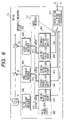
- FIG. 6 shows a third embodiment of the control circuit in the RF-IC 30 for the multimode wireless terminal according to the invention.
- configuration parameters are loaded from the external input pin 31 via the configuration value write controller 401 to all of registers prepared in the parameter storing register block 400 at the time of initial setting.
- some parameters to be set in the RF-IC are unconditionally determined and will not be changed later.
- the frequency characteristics of the output signal are specified by a standard.
- a register as a part of the parameter storing register block 400 may be replaced with a ROM for holding fixed parameters.
- the register 412 can be also replaced with a ROM.
- FIG. 7A shows a fourth embodiment of the control circuit of the RF-IC 30 for the multimode wireless terminal according to the invention.
- configuration parameter values are transferred as reference parameter values from the parameter storing register block 400 to all of the parameter reference registers ( 302 to 304 ). In an actual application, there is a case such that configuration parameters have to be set from the parameter storing register block 400 with respect to only a part of the reference registers.
- the fourth embodiment is characterized in that, for example, like an amplifier gain parameter, a specific parameter of which set value is desired to be changed even in the same communication mode depending on special situations such as a radio propagation state in a wireless path is supplied from the external signal input pin 31 to the parameter reference register 303 , and the other parameters are set from the parameter storing register block 400 to the parameter reference register.
- mixers 34 A and 34 B which become difficult to share the same circuit depending on a combination of selectable communication modes or analog components to be dedicated to respective modes because it is advantageous from the view point of performance and power consumption, are excluded from targets of parameter switching. For some parts of which parameter set values are the same even when the communication mode changes, it is naturally unnecessary to switch the configuration parameters.
- control data CNT 1 and CNT 2 including, for example, a control code P 401 , a mode selection bit P 311 , and an amplifier gain adjustment parameter P 303 to the RF-IC 30 each time the communication mode is switched.
- the time required to switch the communication mode can be shortened while suppressing increase in the scale of the IC and the influence on performance.
- any one of the speech preference mode, wireless LAN preference mode, and user's selection preference mode is designated according to the mode selection rule in the incoming call processing.
- further another mode may be designated according to the mode selection rule.
- a parallel execution mode of executing voice communication by a mobile telephone and data communication by a wireless LAN in parallel in a time sharing manner may be designated.
- voice data is transmitted and received every 125 ⁇ sec
- data of the wireless LAN can be communicated in a time sharing manner by using the intervals of voice data communication in the parallel execution mode.
- the communication mode can be switched at high speed, for example, by increasing the operation speed of the RF-IC 30 , control processor 16 , and DSP 142 or decreasing the data bit rate of the wireless LAN in the parallel execution mode, it is able to offer such a form of communication service that the user is allowed to perform speech communication by a mobile telephone in parallel with display of received data from the wireless LAN to the display unit 22 .
- the communication mode can be switched at high speed. Consequently, it is able to provide a multimode wireless terminal capable of executing plural kinds of communication modes of different communication protocols, like the mobile telephone and the wireless LAN communication, while periodically switching the communication modes.
- the multimode terminal for switching the communication mode between the mobile telephone mode (public network wireless communication) and the wireless LAN mode (local network communication) has been described.
- the method of switching the communication mode according to the invention is also applicable to a combination of communication modes other than the embodiments. For example, alternate switching may be performed between first and second communication modes of the wireless LAN in order to detect a wireless LAN system from which the terminal can receive data, so that a user can enjoy information distribution service provided by the detected wireless LAN system.
Abstract
Description
Claims (16)
Priority Applications (1)
| Application Number | Priority Date | Filing Date | Title |
|---|---|---|---|
| US12/684,256 US20100113089A1 (en) | 2002-10-23 | 2010-01-08 | Multimode wireless communication apparatus and high frequency integrated circuit therefore |
Applications Claiming Priority (2)
| Application Number | Priority Date | Filing Date | Title |
|---|---|---|---|
| JP2002307792 | 2002-10-23 | ||
| JP2002-307792 | 2002-10-23 |
Related Child Applications (1)
| Application Number | Title | Priority Date | Filing Date |
|---|---|---|---|
| US12/684,256 Continuation US20100113089A1 (en) | 2002-10-23 | 2010-01-08 | Multimode wireless communication apparatus and high frequency integrated circuit therefore |
Publications (2)
| Publication Number | Publication Date |
|---|---|
| US20040204038A1 US20040204038A1 (en) | 2004-10-14 |
| US7657282B2 true US7657282B2 (en) | 2010-02-02 |
Family
ID=33111890
Family Applications (2)
| Application Number | Title | Priority Date | Filing Date |
|---|---|---|---|
| US10/372,269 Expired - Lifetime US7657282B2 (en) | 2002-10-23 | 2003-02-25 | Multimode wireless communication apparatus and high frequency integrated circuit therefor |
| US12/684,256 Abandoned US20100113089A1 (en) | 2002-10-23 | 2010-01-08 | Multimode wireless communication apparatus and high frequency integrated circuit therefore |
Family Applications After (1)
| Application Number | Title | Priority Date | Filing Date |
|---|---|---|---|
| US12/684,256 Abandoned US20100113089A1 (en) | 2002-10-23 | 2010-01-08 | Multimode wireless communication apparatus and high frequency integrated circuit therefore |
Country Status (2)
| Country | Link |
|---|---|
| US (2) | US7657282B2 (en) |
| JP (4) | JP5166092B2 (en) |
Cited By (10)
| Publication number | Priority date | Publication date | Assignee | Title |
|---|---|---|---|---|
| US20070275717A1 (en) * | 2006-03-07 | 2007-11-29 | Qualcomm, Incorporated | Network selection by wireless terminals |
| US20070298729A1 (en) * | 2004-08-06 | 2007-12-27 | Kappes Michael S | Multi-mode crystal oscillator |
| US20090203340A1 (en) * | 2006-07-11 | 2009-08-13 | Freescale Semiconductor, Inc. | Receiver for receiving at least two types of signals, data communication system and vehicle including a receiver |
| US20090207817A1 (en) * | 2008-02-15 | 2009-08-20 | Michael Montemurro | Policy-Based Data Routing For A Multi-Mode Device |
| US20100113018A1 (en) * | 2006-09-28 | 2010-05-06 | Junichi Furumi | Wireless Communication Terminal, Communication Control Method of Wireless Communication Terminal, and Wireless Communication System |
| US7974622B1 (en) * | 2007-01-16 | 2011-07-05 | Sprint Communications Company L.P. | Provisioning system for fixed vs. nomadic wireless services |
| US20120302155A1 (en) * | 2010-10-22 | 2012-11-29 | Marsolais Alexandre | Multi-mode communication unit |
| US8412267B2 (en) | 2010-07-26 | 2013-04-02 | Brother Kogyo Kabushiki Kaisha | Communication controlling method, computer readable medium, and communication device |
| US8638463B2 (en) | 2010-07-29 | 2014-01-28 | Brother Kogyo Kabushiki Kaisha | Communication controlling method, computer readable medium, and communication device |
| CN107529112A (en) * | 2016-06-22 | 2017-12-29 | 塞舌尔商元鼎音讯股份有限公司 | The method of audio transmission system and its audio frequency process |
Families Citing this family (41)
| Publication number | Priority date | Publication date | Assignee | Title |
|---|---|---|---|---|
| US8127984B2 (en) * | 2003-06-13 | 2012-03-06 | Varia Holdings Llc | Emulated radio frequency identification |
| KR20050046835A (en) * | 2003-11-14 | 2005-05-19 | 에스케이 텔레콤주식회사 | Method and system for hand-over from wideband code division multiple access network to code division multiple access network by using dummy pilot signal |
| WO2005117473A1 (en) * | 2004-05-28 | 2005-12-08 | Matsushita Electric Industrial Co., Ltd. | Multi-mode control station, radio communication system, radio station, and radio communication control method |
| JP4498105B2 (en) * | 2004-11-19 | 2010-07-07 | キヤノン株式会社 | COMMUNICATION DEVICE AND ITS CONTROL METHOD |
| US7546149B2 (en) * | 2005-03-08 | 2009-06-09 | Motorola, Inc. | Deep sleep mode for portable communication device |
| US8606333B2 (en) * | 2005-06-10 | 2013-12-10 | At&T Mobility Ii Llc | Push to lower hearing assisted device |
| KR100714699B1 (en) * | 2005-08-25 | 2007-05-07 | 삼성전자주식회사 | Wireless transceiver supporting plurality of communication/broadcast service |
| US7577779B2 (en) * | 2006-02-14 | 2009-08-18 | Broadcom Corporation | Method and system for a RFIC master |
| US7869824B2 (en) * | 2006-09-06 | 2011-01-11 | Byung Woo Min | Cell phone with remote control system |
| US7953439B2 (en) * | 2006-12-19 | 2011-05-31 | Broadcom Corporation | Voice-data-RF integrated circuit |
| US20080146281A1 (en) * | 2006-12-19 | 2008-06-19 | Broadcom Corporation, A California Corporation | Cellular telephone IC and applications thereof |
| US7817042B2 (en) * | 2007-02-23 | 2010-10-19 | Cisco Technology, Inc. | RFID tag management and operation |
| US20080242347A1 (en) * | 2007-03-30 | 2008-10-02 | Nokia Corporation | Fast multiradio context switching |
| US8792118B2 (en) | 2007-09-26 | 2014-07-29 | Ringcentral Inc. | User interfaces and methods to provision electronic facsimiles |
| US8838082B2 (en) | 2008-11-26 | 2014-09-16 | Ringcentral, Inc. | Centralized status server for call management of location-aware mobile devices |
| US8275110B2 (en) | 2007-09-28 | 2012-09-25 | Ringcentral, Inc. | Active call filtering, screening and dispatching |
| US8670545B2 (en) | 2007-09-28 | 2014-03-11 | Ringcentral, Inc. | Inbound call identification and management |
| US8600391B2 (en) | 2008-11-24 | 2013-12-03 | Ringcentral, Inc. | Call management for location-aware mobile devices |
| US20090221232A1 (en) * | 2008-02-29 | 2009-09-03 | Estevez Leonardo W | Portable Telephone With Unitary Transceiver Having Cellular and RFID Functionality |
| US8369265B2 (en) * | 2008-08-07 | 2013-02-05 | Ringcentral, Inc. | Remote call control for mobile telecommunication devices and services |
| JP2010087828A (en) * | 2008-09-30 | 2010-04-15 | Fujitsu Ltd | Near mimo repeater device, near mimo portable remote terminal device and near mimo radio communication method |
| US8780383B2 (en) | 2008-11-25 | 2014-07-15 | Ringcentral, Inc. | Authenticated facsimile transmission from mobile devices |
| JP5212045B2 (en) * | 2008-11-25 | 2013-06-19 | 日本電気株式会社 | Wireless communication device and communication method |
| US20110319085A1 (en) * | 2009-02-26 | 2011-12-29 | Ntt Docomo, Inc. | Controller, radio network controller, base station apparatus, and communication control method |
| JP4703739B2 (en) * | 2009-03-19 | 2011-06-15 | 株式会社エヌ・ティ・ティ・ドコモ | Communication method and mobile device |
| US8078152B2 (en) * | 2009-08-13 | 2011-12-13 | Palo Alto Research Center Incorporated | Venue inference using data sensed by mobile devices |
| US9002350B1 (en) | 2010-09-02 | 2015-04-07 | Ringcentral, Inc. | Unified caller identification across multiple communication modes |
| US8369847B1 (en) | 2010-09-13 | 2013-02-05 | Ringcentral, Inc. | Mobile devices having a common communication mode |
| JP6012160B2 (en) | 2011-11-10 | 2016-10-25 | キヤノン株式会社 | COMMUNICATION DEVICE, COMMUNICATION DEVICE CONTROL METHOD, IMAGING DEVICE, IMAGING DEVICE CONTROL METHOD, PROGRAM |
| CN102625416B (en) * | 2012-03-28 | 2015-03-18 | 华为技术有限公司 | Working method of multimode terminal and multimode terminal |
| US8467514B1 (en) | 2012-04-09 | 2013-06-18 | Ringcentral, Inc. | Cross-platform presence |
| JP2014150501A (en) * | 2013-02-04 | 2014-08-21 | Sharp Corp | Mobile terminal device |
| JP2014195167A (en) * | 2013-03-28 | 2014-10-09 | Nippon Telegraph & Telephone East Corp | Telephone system and method for the same |
| EP3036852B1 (en) | 2013-08-21 | 2022-05-11 | Aviat Networks, Inc. | Systems and methods for adaptive repeaters |
| TWI647920B (en) * | 2014-01-23 | 2019-01-11 | 美國麻省理工學院 | An integrated circuit adapted for mobile communication and related mobile computing device |
| US9362988B2 (en) * | 2014-10-28 | 2016-06-07 | Qualcomm Incorporated | WWAN and WLAN cooperative support of multi-SIM devices |
| US9787491B2 (en) * | 2015-03-20 | 2017-10-10 | Landis & Gyr Innovations, Inc. | Interleaved communication with resource providers and a home area network |
| CN106454692A (en) * | 2015-08-12 | 2017-02-22 | 卢迪 | Dual-mode wireless communication chip, dual-mode wireless communication equipment and dual-mode wireless communication method |
| JP2019153844A (en) * | 2018-02-28 | 2019-09-12 | 株式会社東芝 | Communication device, communication method, and program |
| US10419077B1 (en) | 2018-03-28 | 2019-09-17 | Google Llc | Wireless communication via a mobile relay |
| US10819457B1 (en) * | 2019-07-30 | 2020-10-27 | Motorola Solutions, Inc. | Interference mitigation between cellular and frequency-modulated communication subsystems in a portable communication device |
Citations (22)
| Publication number | Priority date | Publication date | Assignee | Title |
|---|---|---|---|---|
| US4092594A (en) * | 1975-05-30 | 1978-05-30 | Masco Corporation Of Indiana | Crystalless scanning radio receiver controlled by processing means |
| US4220922A (en) * | 1977-01-25 | 1980-09-02 | Sanyo Electric Co. Ltd. | Preset tuner |
| US4291414A (en) * | 1979-05-02 | 1981-09-22 | Nippon Gakki Seizo Kabushiki Kaisha | Radio receiver operable in station search mode or station select mode |
| JPS6461480A (en) | 1987-08-31 | 1989-03-08 | Nippon Mining Co | Phthalocyanine analog |
| US5020093A (en) * | 1989-06-23 | 1991-05-28 | Motorola, Inc. | Cellular telephone operable on different cellular telephone systems |
| JPH05160784A (en) | 1991-12-09 | 1993-06-25 | Matsushita Electric Ind Co Ltd | Portable radio telephone set |
| JPH05189814A (en) | 1992-01-13 | 1993-07-30 | Canon Inc | Manufacture of original plate for optical recording medium manufacture |
| US5422931A (en) * | 1993-09-22 | 1995-06-06 | Hughes Aircraft Company | Dual mode portable cellular telephone having switch control of the rf signal path to effectuate power savings |
| WO1998020635A2 (en) | 1996-11-06 | 1998-05-14 | Philips Electronics N.V. | A radio receiver for receiving a main radio broadcast signal and a monolythic integrated circuit for use in such radio receiver |
| US6011960A (en) * | 1991-11-25 | 2000-01-04 | Matsushita Electric Industrial Co., Ltd. | Telephone handset for operating in a plurality of wireless telephone system |
| US6185418B1 (en) * | 1997-11-07 | 2001-02-06 | Lucent Technologies Inc. | Adaptive digital radio communication system |
| US6249686B1 (en) * | 1998-12-22 | 2001-06-19 | Philips Electronics N.A. Corp. | Internal circuit for adaptive mode selection of multi-mode RF integrated circuit |
| US20010010889A1 (en) | 1998-04-17 | 2001-08-02 | Akihiro Horii | Developing paper |
| US6389277B1 (en) * | 1999-02-25 | 2002-05-14 | Denso Corporation | Cellular call mode determining device |
| US6453172B1 (en) * | 1998-04-13 | 2002-09-17 | Nec Corporation | Dual band portable phone switchable between different phone systems |
| US6466803B1 (en) * | 1999-10-19 | 2002-10-15 | Qualcomm, Incorporated | Multi-mode communications system with efficient oscillator synchronization |
| US6597782B1 (en) * | 2000-03-31 | 2003-07-22 | Alcatel | Method and apparatus for providing control and input sensing in a signal transfer point |
| US6640115B1 (en) * | 1998-04-01 | 2003-10-28 | Sharp Kabushiki Kaisha | Radio communication apparatus having speed judging circuitry |
| US6643522B1 (en) * | 2000-03-27 | 2003-11-04 | Sharp Laboratories Of America, Inc. | Method and apparatus providing simultaneous dual mode operations for radios in the shared spectrum |
| US6731349B1 (en) * | 1999-07-13 | 2004-05-04 | Koninklijke Philips Electronics N.V. | Tuner with at least a first and a second frequency band |
| US6804497B2 (en) * | 2001-01-12 | 2004-10-12 | Silicon Laboratories, Inc. | Partitioned radio-frequency apparatus and associated methods |
| US7046649B2 (en) * | 2000-01-20 | 2006-05-16 | Agere Systems Inc. | Interoperability for bluetooth/IEEE 802.11 |
Family Cites Families (24)
| Publication number | Priority date | Publication date | Assignee | Title |
|---|---|---|---|---|
| JPS63253730A (en) * | 1987-04-09 | 1988-10-20 | Nec Corp | Power amplifier |
| JPH0563551A (en) * | 1991-08-29 | 1993-03-12 | Kawasaki Steel Corp | Programmable logic circuit device |
| US5452289A (en) * | 1993-01-08 | 1995-09-19 | Multi-Tech Systems, Inc. | Computer-based multifunction personal communications system |
| JPH09172572A (en) * | 1995-12-20 | 1997-06-30 | Sanyo Electric Co Ltd | Parameter setting circuit |
| US5884188A (en) * | 1996-09-18 | 1999-03-16 | Ericsson Inc. | Received signal selection system for combined pager/cellular telephone apparatus |
| JPH11250031A (en) * | 1998-02-26 | 1999-09-17 | Hitachi Ltd | Programmable logic and information processor |
| JPH11285066A (en) * | 1998-03-27 | 1999-10-15 | Kokusai Electric Co Ltd | Mobile communication system |
| JP2000023253A (en) * | 1998-06-26 | 2000-01-21 | Nec Corp | Multimode mobile radio device and multimode radio device, and incoming call information method for the same |
| JP2000184438A (en) * | 1998-12-14 | 2000-06-30 | Kyocera Corp | Mobile radio communication equipment |
| JP3428481B2 (en) * | 1998-12-28 | 2003-07-22 | 株式会社東芝 | transceiver |
| US6728215B1 (en) * | 1998-12-30 | 2004-04-27 | Ericsson Inc. | System and method for placing wireless calls on an internet protocol based local area network based upon quality of service conditions |
| JP2000236357A (en) * | 1999-02-16 | 2000-08-29 | Canon Inc | Device and method for processing information |
| US6614769B1 (en) * | 1999-06-01 | 2003-09-02 | Motorola, Inc. | Communications unit for seamless handover between networks and method of use therefor |
| JP2001025069A (en) * | 1999-07-09 | 2001-01-26 | Toshiba Corp | Radio telephone terminal |
| FI19991833A (en) * | 1999-08-30 | 2001-02-28 | Nokia Mobile Phones Ltd | A method for connecting calls in a mobile communication system |
| JP3878385B2 (en) * | 2000-02-18 | 2007-02-07 | 三菱電機株式会社 | Wireless communication apparatus, wireless communication method, receiver, and transmitter |
| US7054290B1 (en) * | 2000-03-07 | 2006-05-30 | Telefonaktiebolaget Lm Ericsson (Publ) | Methods and apparatus for dual mode operation in a wireless communication system |
| JP2002064877A (en) * | 2000-08-22 | 2002-02-28 | Sony Corp | Communication system and communication terminal |
| JP2002076965A (en) * | 2000-08-28 | 2002-03-15 | Telecommunication Advancement Organization Of Japan | Radio terminal, record medium recording updated program of its communication system software and its base station |
| US7039027B2 (en) * | 2000-12-28 | 2006-05-02 | Symbol Technologies, Inc. | Automatic and seamless vertical roaming between wireless local area network (WLAN) and wireless wide area network (WWAN) while maintaining an active voice or streaming data connection: systems, methods and program products |
| US8019335B2 (en) * | 2001-01-29 | 2011-09-13 | Nokia Corporation | Identifying neighboring cells in telecommunication network |
| US20020102973A1 (en) * | 2001-01-29 | 2002-08-01 | Rosenberg William Harry | Intelligent roaming method for enabling a mobile station to select a preferred neutral service provider within a communication system |
| US20030134650A1 (en) * | 2002-01-17 | 2003-07-17 | Rangamani Sundar | Method, system and apparatus for internetworking a mobile station to operate in a WWAN environment and in a WLAN environment with PBX services |
| WO2004025982A1 (en) * | 2002-09-11 | 2004-03-25 | Docomo Communications Laboratories Europe Gmbh | Middleware platform |
-
2003
- 2003-02-25 US US10/372,269 patent/US7657282B2/en not_active Expired - Lifetime
-
2008
- 2008-03-27 JP JP2008083253A patent/JP5166092B2/en not_active Expired - Lifetime
-
2010
- 2010-01-08 US US12/684,256 patent/US20100113089A1/en not_active Abandoned
-
2011
- 2011-09-05 JP JP2011192716A patent/JP5877024B2/en not_active Expired - Lifetime
-
2013
- 2013-06-24 JP JP2013131227A patent/JP5685687B2/en not_active Expired - Lifetime
-
2015
- 2015-02-05 JP JP2015021223A patent/JP2015133713A/en active Pending
Patent Citations (22)
| Publication number | Priority date | Publication date | Assignee | Title |
|---|---|---|---|---|
| US4092594A (en) * | 1975-05-30 | 1978-05-30 | Masco Corporation Of Indiana | Crystalless scanning radio receiver controlled by processing means |
| US4220922A (en) * | 1977-01-25 | 1980-09-02 | Sanyo Electric Co. Ltd. | Preset tuner |
| US4291414A (en) * | 1979-05-02 | 1981-09-22 | Nippon Gakki Seizo Kabushiki Kaisha | Radio receiver operable in station search mode or station select mode |
| JPS6461480A (en) | 1987-08-31 | 1989-03-08 | Nippon Mining Co | Phthalocyanine analog |
| US5020093A (en) * | 1989-06-23 | 1991-05-28 | Motorola, Inc. | Cellular telephone operable on different cellular telephone systems |
| US6011960A (en) * | 1991-11-25 | 2000-01-04 | Matsushita Electric Industrial Co., Ltd. | Telephone handset for operating in a plurality of wireless telephone system |
| JPH05160784A (en) | 1991-12-09 | 1993-06-25 | Matsushita Electric Ind Co Ltd | Portable radio telephone set |
| JPH05189814A (en) | 1992-01-13 | 1993-07-30 | Canon Inc | Manufacture of original plate for optical recording medium manufacture |
| US5422931A (en) * | 1993-09-22 | 1995-06-06 | Hughes Aircraft Company | Dual mode portable cellular telephone having switch control of the rf signal path to effectuate power savings |
| WO1998020635A2 (en) | 1996-11-06 | 1998-05-14 | Philips Electronics N.V. | A radio receiver for receiving a main radio broadcast signal and a monolythic integrated circuit for use in such radio receiver |
| US6185418B1 (en) * | 1997-11-07 | 2001-02-06 | Lucent Technologies Inc. | Adaptive digital radio communication system |
| US6640115B1 (en) * | 1998-04-01 | 2003-10-28 | Sharp Kabushiki Kaisha | Radio communication apparatus having speed judging circuitry |
| US6453172B1 (en) * | 1998-04-13 | 2002-09-17 | Nec Corporation | Dual band portable phone switchable between different phone systems |
| US20010010889A1 (en) | 1998-04-17 | 2001-08-02 | Akihiro Horii | Developing paper |
| US6249686B1 (en) * | 1998-12-22 | 2001-06-19 | Philips Electronics N.A. Corp. | Internal circuit for adaptive mode selection of multi-mode RF integrated circuit |
| US6389277B1 (en) * | 1999-02-25 | 2002-05-14 | Denso Corporation | Cellular call mode determining device |
| US6731349B1 (en) * | 1999-07-13 | 2004-05-04 | Koninklijke Philips Electronics N.V. | Tuner with at least a first and a second frequency band |
| US6466803B1 (en) * | 1999-10-19 | 2002-10-15 | Qualcomm, Incorporated | Multi-mode communications system with efficient oscillator synchronization |
| US7046649B2 (en) * | 2000-01-20 | 2006-05-16 | Agere Systems Inc. | Interoperability for bluetooth/IEEE 802.11 |
| US6643522B1 (en) * | 2000-03-27 | 2003-11-04 | Sharp Laboratories Of America, Inc. | Method and apparatus providing simultaneous dual mode operations for radios in the shared spectrum |
| US6597782B1 (en) * | 2000-03-31 | 2003-07-22 | Alcatel | Method and apparatus for providing control and input sensing in a signal transfer point |
| US6804497B2 (en) * | 2001-01-12 | 2004-10-12 | Silicon Laboratories, Inc. | Partitioned radio-frequency apparatus and associated methods |
Cited By (17)
| Publication number | Priority date | Publication date | Assignee | Title |
|---|---|---|---|---|
| US7848709B2 (en) * | 2004-08-06 | 2010-12-07 | Broadcom Corporation | Multi-mode crystal oscillator |
| US20070298729A1 (en) * | 2004-08-06 | 2007-12-27 | Kappes Michael S | Multi-mode crystal oscillator |
| US8437288B2 (en) * | 2006-03-07 | 2013-05-07 | Qualcomm Incorporated | Network selection by wireless terminals |
| US20070275717A1 (en) * | 2006-03-07 | 2007-11-29 | Qualcomm, Incorporated | Network selection by wireless terminals |
| US20090203340A1 (en) * | 2006-07-11 | 2009-08-13 | Freescale Semiconductor, Inc. | Receiver for receiving at least two types of signals, data communication system and vehicle including a receiver |
| US8369849B2 (en) * | 2006-09-28 | 2013-02-05 | Kyocera Corporation | Wireless communication terminal, communication control method of wireless communication terminal, and wireless communication system |
| US20100113018A1 (en) * | 2006-09-28 | 2010-05-06 | Junichi Furumi | Wireless Communication Terminal, Communication Control Method of Wireless Communication Terminal, and Wireless Communication System |
| US7974622B1 (en) * | 2007-01-16 | 2011-07-05 | Sprint Communications Company L.P. | Provisioning system for fixed vs. nomadic wireless services |
| US20090207817A1 (en) * | 2008-02-15 | 2009-08-20 | Michael Montemurro | Policy-Based Data Routing For A Multi-Mode Device |
| US8825109B2 (en) * | 2008-02-15 | 2014-09-02 | Blackberry Limited | Policy-based data routing for a multi-mode device |
| US9720735B2 (en) | 2008-02-15 | 2017-08-01 | Blackberry Limited | Policy-based data routing for a multi-mode device |
| US8412267B2 (en) | 2010-07-26 | 2013-04-02 | Brother Kogyo Kabushiki Kaisha | Communication controlling method, computer readable medium, and communication device |
| US8638463B2 (en) | 2010-07-29 | 2014-01-28 | Brother Kogyo Kabushiki Kaisha | Communication controlling method, computer readable medium, and communication device |
| US20120302155A1 (en) * | 2010-10-22 | 2012-11-29 | Marsolais Alexandre | Multi-mode communication unit |
| US8666341B2 (en) * | 2010-10-22 | 2014-03-04 | Ultra Electronics Tcs Inc. | Multi-mode communication unit |
| CN107529112A (en) * | 2016-06-22 | 2017-12-29 | 塞舌尔商元鼎音讯股份有限公司 | The method of audio transmission system and its audio frequency process |
| CN107529112B (en) * | 2016-06-22 | 2021-01-22 | 原相科技股份有限公司 | Audio transmission system and audio processing method thereof |
Also Published As
| Publication number | Publication date |
|---|---|
| JP2015133713A (en) | 2015-07-23 |
| US20100113089A1 (en) | 2010-05-06 |
| JP5877024B2 (en) | 2016-03-02 |
| US20040204038A1 (en) | 2004-10-14 |
| JP5685687B2 (en) | 2015-03-18 |
| JP5166092B2 (en) | 2013-03-21 |
| JP2013232945A (en) | 2013-11-14 |
| JP2012029314A (en) | 2012-02-09 |
| JP2008252894A (en) | 2008-10-16 |
Similar Documents
| Publication | Publication Date | Title |
|---|---|---|
| US7657282B2 (en) | Multimode wireless communication apparatus and high frequency integrated circuit therefor | |
| US8755747B2 (en) | Techniques to control transmit power for a shared antenna architecture | |
| US8583057B2 (en) | Techniques to control a shared antenna architecture for multiple co-located radio modules | |
| JP4933099B2 (en) | Method and terminal for initiating measurement of signal power level in a terminal of a cellular network | |
| US20070121536A1 (en) | Mobile communication terminal and computer readable recording medium | |
| JPH1023538A (en) | Mobile communication terminal device and its portable telephone | |
| CN101213779A (en) | Terminal assisted WLAN access point rate adaptation | |
| US7305259B1 (en) | Apparatus and method for reducing power consumption in wireless RF systems | |
| EP2088680B1 (en) | Apparatus for impedance matching in dual standby portable terminal and method thereof | |
| JP4300071B2 (en) | Multi-mode wireless communication device and high-frequency integrated circuit used therefor | |
| JP3751205B2 (en) | Communication device and communication control method | |
| JP4364572B2 (en) | Wireless communication terminal | |
| US20040223479A1 (en) | Method of interference control and radio terminal equipment arrangement | |
| JP4107784B2 (en) | Mobile radio system | |
| JP3828038B2 (en) | Communication apparatus and base station selection method | |
| JP2000092543A (en) | Mobile radio terminal equipment | |
| US20070026890A1 (en) | Private branch exchange | |
| US6973117B1 (en) | Dynamic extension of frequency hopping patterns in wireless communications | |
| JP2004088523A (en) | Portable telephone system, communication line switching method used for same and its program | |
| KR100500955B1 (en) | RF module control of DC station | |
| JP3742298B2 (en) | Mobile radio communication device | |
| KR20090091384A (en) | Wireless communication system and its method having bluetooth module and wlan module | |
| KR20060039233A (en) | Method for controlling received call of mobile communication terminal with bluetooth | |
| JP2002185636A (en) | Mobile communication terminal equipment, its portable telephone set and data terminal equipment | |
| KR20000015296A (en) | Method of displaying communication failing reason in second generation cordless telephone |
Legal Events
| Date | Code | Title | Description |
|---|---|---|---|
| AS | Assignment |
Owner name: HITACHI, LTD., JAPAN Free format text: ASSIGNMENT OF ASSIGNORS INTEREST;ASSIGNORS:SUZUKI, MAY;YAMAWAKI, TAIZO;TANAKA, SATOSHI;AND OTHERS;REEL/FRAME:013808/0687;SIGNING DATES FROM 20030130 TO 20030214 Owner name: HITACHI, LTD.,JAPAN Free format text: ASSIGNMENT OF ASSIGNORS INTEREST;ASSIGNORS:SUZUKI, MAY;YAMAWAKI, TAIZO;TANAKA, SATOSHI;AND OTHERS;SIGNING DATES FROM 20030130 TO 20030214;REEL/FRAME:013808/0687 |
|
| STCF | Information on status: patent grant |
Free format text: PATENTED CASE |
|
| FEPP | Fee payment procedure |
Free format text: PAYOR NUMBER ASSIGNED (ORIGINAL EVENT CODE: ASPN); ENTITY STATUS OF PATENT OWNER: LARGE ENTITY Free format text: PAYER NUMBER DE-ASSIGNED (ORIGINAL EVENT CODE: RMPN); ENTITY STATUS OF PATENT OWNER: LARGE ENTITY |
|
| AS | Assignment |
Owner name: HITACHI CONSUMER ELECTRONICS CO., LTD., JAPAN Free format text: ASSIGNMENT OF ASSIGNORS INTEREST;ASSIGNOR:HITACHI, LTD.;REEL/FRAME:030648/0217 Effective date: 20130607 |
|
| FPAY | Fee payment |
Year of fee payment: 4 |
|
| AS | Assignment |
Owner name: HITACHI MAXELL, LTD., JAPAN Free format text: ASSIGNMENT OF ASSIGNORS INTEREST;ASSIGNORS:HITACHI CONSUMER ELECTRONICS CO., LTD.;HITACHI CONSUMER ELECTRONICS CO, LTD.;REEL/FRAME:033694/0745 Effective date: 20140826 |
|
| FPAY | Fee payment |
Year of fee payment: 8 |
|
| AS | Assignment |
Owner name: MAXELL, LTD., JAPAN Free format text: ASSIGNMENT OF ASSIGNORS INTEREST;ASSIGNOR:HITACHI MAXELL, LTD.;REEL/FRAME:045142/0208 Effective date: 20171001 |
|
| MAFP | Maintenance fee payment |
Free format text: PAYMENT OF MAINTENANCE FEE, 12TH YEAR, LARGE ENTITY (ORIGINAL EVENT CODE: M1553); ENTITY STATUS OF PATENT OWNER: LARGE ENTITY Year of fee payment: 12 |
|
| AS | Assignment |
Owner name: MAXELL HOLDINGS, LTD., JAPAN Free format text: MERGER;ASSIGNOR:MAXELL, LTD.;REEL/FRAME:058255/0579 Effective date: 20211001 |
|
| AS | Assignment |
Owner name: MAXELL, LTD., JAPAN Free format text: CHANGE OF NAME;ASSIGNOR:MAXELL HOLDINGS, LTD.;REEL/FRAME:058666/0407 Effective date: 20211001 |