US7656375B2 - Image-processing device and method for enhancing the luminance and the image quality of display panels - Google Patents
Image-processing device and method for enhancing the luminance and the image quality of display panels Download PDFInfo
- Publication number
- US7656375B2 US7656375B2 US11/298,529 US29852905A US7656375B2 US 7656375 B2 US7656375 B2 US 7656375B2 US 29852905 A US29852905 A US 29852905A US 7656375 B2 US7656375 B2 US 7656375B2
- Authority
- US
- United States
- Prior art keywords
- image
- color
- data
- luminance
- block
- Prior art date
- Legal status (The legal status is an assumption and is not a legal conclusion. Google has not performed a legal analysis and makes no representation as to the accuracy of the status listed.)
- Expired - Fee Related, expires
Links
- 230000002708 enhancing effect Effects 0.000 title claims abstract description 9
- 238000000034 method Methods 0.000 title abstract description 15
- 239000003086 colorant Substances 0.000 claims description 40
- 238000003672 processing method Methods 0.000 claims description 14
- 239000004973 liquid crystal related substance Substances 0.000 claims description 4
- 230000003287 optical effect Effects 0.000 claims description 4
- 230000001965 increasing effect Effects 0.000 description 18
- 238000010586 diagram Methods 0.000 description 17
- 230000000694 effects Effects 0.000 description 8
- 238000004364 calculation method Methods 0.000 description 3
- 230000003247 decreasing effect Effects 0.000 description 3
- 230000003044 adaptive effect Effects 0.000 description 2
- 230000000452 restraining effect Effects 0.000 description 1
- 230000000717 retained effect Effects 0.000 description 1
Images


Classifications
-
- G—PHYSICS
- G09—EDUCATION; CRYPTOGRAPHY; DISPLAY; ADVERTISING; SEALS
- G09G—ARRANGEMENTS OR CIRCUITS FOR CONTROL OF INDICATING DEVICES USING STATIC MEANS TO PRESENT VARIABLE INFORMATION
- G09G3/00—Control arrangements or circuits, of interest only in connection with visual indicators other than cathode-ray tubes
- G09G3/20—Control arrangements or circuits, of interest only in connection with visual indicators other than cathode-ray tubes for presentation of an assembly of a number of characters, e.g. a page, by composing the assembly by combination of individual elements arranged in a matrix no fixed position being assigned to or needed to be assigned to the individual characters or partial characters
- G09G3/34—Control arrangements or circuits, of interest only in connection with visual indicators other than cathode-ray tubes for presentation of an assembly of a number of characters, e.g. a page, by composing the assembly by combination of individual elements arranged in a matrix no fixed position being assigned to or needed to be assigned to the individual characters or partial characters by control of light from an independent source
- G09G3/36—Control arrangements or circuits, of interest only in connection with visual indicators other than cathode-ray tubes for presentation of an assembly of a number of characters, e.g. a page, by composing the assembly by combination of individual elements arranged in a matrix no fixed position being assigned to or needed to be assigned to the individual characters or partial characters by control of light from an independent source using liquid crystals
- G09G3/3607—Control arrangements or circuits, of interest only in connection with visual indicators other than cathode-ray tubes for presentation of an assembly of a number of characters, e.g. a page, by composing the assembly by combination of individual elements arranged in a matrix no fixed position being assigned to or needed to be assigned to the individual characters or partial characters by control of light from an independent source using liquid crystals for displaying colours or for displaying grey scales with a specific pixel layout, e.g. using sub-pixels
-
- G—PHYSICS
- G09—EDUCATION; CRYPTOGRAPHY; DISPLAY; ADVERTISING; SEALS
- G09G—ARRANGEMENTS OR CIRCUITS FOR CONTROL OF INDICATING DEVICES USING STATIC MEANS TO PRESENT VARIABLE INFORMATION
- G09G2320/00—Control of display operating conditions
- G09G2320/06—Adjustment of display parameters
- G09G2320/0626—Adjustment of display parameters for control of overall brightness
- G09G2320/0646—Modulation of illumination source brightness and image signal correlated to each other
-
- G—PHYSICS
- G09—EDUCATION; CRYPTOGRAPHY; DISPLAY; ADVERTISING; SEALS
- G09G—ARRANGEMENTS OR CIRCUITS FOR CONTROL OF INDICATING DEVICES USING STATIC MEANS TO PRESENT VARIABLE INFORMATION
- G09G2320/00—Control of display operating conditions
- G09G2320/06—Adjustment of display parameters
- G09G2320/0666—Adjustment of display parameters for control of colour parameters, e.g. colour temperature
-
- G—PHYSICS
- G09—EDUCATION; CRYPTOGRAPHY; DISPLAY; ADVERTISING; SEALS
- G09G—ARRANGEMENTS OR CIRCUITS FOR CONTROL OF INDICATING DEVICES USING STATIC MEANS TO PRESENT VARIABLE INFORMATION
- G09G2340/00—Aspects of display data processing
- G09G2340/06—Colour space transformation
-
- G—PHYSICS
- G09—EDUCATION; CRYPTOGRAPHY; DISPLAY; ADVERTISING; SEALS
- G09G—ARRANGEMENTS OR CIRCUITS FOR CONTROL OF INDICATING DEVICES USING STATIC MEANS TO PRESENT VARIABLE INFORMATION
- G09G2360/00—Aspects of the architecture of display systems
- G09G2360/16—Calculation or use of calculated indices related to luminance levels in display data
-
- G—PHYSICS
- G09—EDUCATION; CRYPTOGRAPHY; DISPLAY; ADVERTISING; SEALS
- G09G—ARRANGEMENTS OR CIRCUITS FOR CONTROL OF INDICATING DEVICES USING STATIC MEANS TO PRESENT VARIABLE INFORMATION
- G09G3/00—Control arrangements or circuits, of interest only in connection with visual indicators other than cathode-ray tubes
- G09G3/20—Control arrangements or circuits, of interest only in connection with visual indicators other than cathode-ray tubes for presentation of an assembly of a number of characters, e.g. a page, by composing the assembly by combination of individual elements arranged in a matrix no fixed position being assigned to or needed to be assigned to the individual characters or partial characters
- G09G3/34—Control arrangements or circuits, of interest only in connection with visual indicators other than cathode-ray tubes for presentation of an assembly of a number of characters, e.g. a page, by composing the assembly by combination of individual elements arranged in a matrix no fixed position being assigned to or needed to be assigned to the individual characters or partial characters by control of light from an independent source
- G09G3/3406—Control of illumination source
Definitions
- the present invention relates to an image-processing device and method for enhancing the luminance and the image quality of display panels. It is an RGBW-color system, which can display a high-quality color and preserve the image-display quality so as to achieve the goals of increasing luminance double, preserving hues and saturation of colors, and preserving the image-contrast quality concurrently.
- pixels of some panels are composed of four sub-pixels. There are red (R), green (G), blue (B), and white (W) sub-pixels.
- RGBW color system can improve the optical efficiency of liquid-crystal displays, where the sub-pixels are arranged as shown in FIGS. 1 and 2 .
- U.S. Pat. No. 5,929,843 proposed an RGB-to-RGBW image-data converting and processing method as shown in FIG. 3 where R, G, and B are inputs of the image color, and R′, G′, B′ and W′ are outputs of the image color, and a minimum-value extractor 11 that chooses the value W′ for white light to emit.
- the algorithm is as follows:
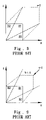
- FIG. 4 The schematic diagram for color space is shown in FIG. 4 .
- all schematic diagrams for color space are expressed as two dimensions (G) and (R).
- point A represents the original image color (RGB)
- point A′ represents the resultant image color (R′G′B′) after the processing according to the algorithm.
- W′ min(s ⁇ R, s ⁇ G, s ⁇ B)
- point B represents the original image color (RGB) while point B′ represents the resultant image color (R′G′B′) after the processing according to the algorithm.
- a prescribed luminance-enhancement gain w will be sent to the color distortion analyzer 22 .
- the color distortion analyzer 22 will calculate the color-distortion value e for the image before and after the luminance enhancement according to the inputted original image color (RGB) data and the luminance-enhancement gain w. If the calculated color-distortion value e is greater than the critical value, the w controller 23 will lower the luminance-enhancement gain w, and a new luminance-enhancement gain w will be sent to the color distortion analyzer 22 to recount the color-distortion value e. Based on this loop, the process will continue until the color-distortion value e is smaller than the critical value.
- the luminance-enhancement gain w is sent to the RGBW converter 21 at this time.
- different images have different luminance-enhancement gains w so as to control the color-distortion value e before and after the luminance enhancement for different images to be lower than the critical value, and to restrain the phenomenon of too large variation of the simultaneous contrast before and after the luminance enhancement for some images.
- the main purpose of the current invention is to enhance the luminance of the displayed image color under the condition of retaining the hue and saturation of the original image.
- Another purpose of the current invention is to overcome the phenomenon of too large variation of the simultaneous contrast after the luminance enhancement for images so as to enhance the contrast quality and effect of the displayed image after the luminance enhancement.
- the present invention has the third purpose that it will not spend complicated and much investment of hardware and image calculation, and it efficiently reduces the operation quantity of the image processing so as to save the investment for circuit hardware.
- the fourth purpose of the present invention is that without sacrificing the luminance enhancement, the image-display quality can still be preserved so as to achieve the goals of increasing luminance double, preserving hues and saturation of colors, and preserving the image-contrast quality concurrently.
- the present invention is an image-processing device for enhancing the luminance and the image quality of display panels, which is a device and method of RGBW color system for improving the optical efficiency of liquid-crystal displays.
- the device and method includes a color distribution-calculating unit that classifies the original image-color data. The relation of the colors located in the color space is divided into block B 1 and block B 2 and then calculates the ratio of the color data in any one of block B 1 or block B 2 to all input image-color data.
- a control-variable generating unit determines the value of the converting-control variable and the value of the backlight luminance-control variable according to the ratio.
- the converting-control variable will be output to a data-converting unit, and the data-converting unit converts the original image-color (RGB) data to the new image-color (R′G′B′W′) data according to the converting-control variable.
- the backlight luminance-control variable will be output to a backlight luminance-control unit so as to control the backlight luminance according to the input backlight luminance-control variable.
- FIG. 1 is the schematic diagram for the prior sub-pixel arrangement for the RGBW.
- FIG. 2 is another schematic diagram for the prior sub-pixel arrangement for the RGBW.
- FIG. 3 is the schematic diagram for the image-processing method of U.S. Pat. No. 5,929,843.
- FIG. 4 is the schematic diagram for the color space of U.S. Pat. No. 5,929,843.
- FIG. 5 is the schematic diagram for the color space of U.S. Pat. No. 6,724,934. (The data are classified block B 1 .)
- FIG. 6 is the schematic diagram for the color space of U.S. Pat. No. 6,724,934. (The data are classified block B 2 .)
- FIG. 7 is the schematic diagram for the image-data numerical converting and processing proposed by the Samsung Company.
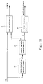
- FIG. 11 is the schematic diagram for the image-processing method of the present invention.
- FIG. 11 is the schematic diagram for the image-processing method of the present invention.
- the color distribution-calculating unit 32 inputs the original image-color (RGB) data.
- the color distribution-calculating unit 32 classifies each pixel-color of the input image. According to the data relation among colors red (R), green (G), and blue (B), the relation of the colors located in the color space is divided into block B 1 and block B 2 (as shown in FIG. 12 ), and then calculates the ratio of the color data in any one of block B 1 or block B 2 . (In the subsequent description, the ratio p (1 ⁇ p ⁇ 0) for calculating the input image-color in block B 2 is used to illustrate the present invention.)
- the data relation among colors red (R), green (G), and blue (B) in block B 1 is: max(R,G,B)/min(R,G,B) ⁇ 2, and the data relation among colors red (R), green (G), and blue (B) in block B 2 is: max(R,G,B)/min(R,G,B)>2.
- the control-variable generating unit 33 that determines the value of the converting-control variable s and the value of the backlight luminance-control variable b according to the ratio p output by the color distribution calculating unit 32 .
- the converting-control variable s will be output to the RGB-to-RGBW data-converting unit 31
- the backlight luminance-control variable b will be output to the backlight luminance-control unit 34 .
- the backlight luminance-control unit 34 controls the backlight luminance of the display panel according to the backlight luminance-control variable b (2 ⁇ b ⁇ 1).
- b the backlight luminance is kept at the original value; when b equals 2, the backlight luminance is increased to double of the original value.
- the backlight luminance-control variable b equals 1
- the converting-control variable s equals 2, which represents that all colors of the input image are located in the block B 1 . Consequently, the backlight luminance retains the original value; the effect of double luminance is achieved.
- the ratio p for calculating the input image-color in block B 2 equals 0.4
- the backlight luminance-control variable b equals 1.4
- the converting-control variable s equals 1.43, which represents that 40% colors of the input image are located in the block B 2 . Consequently, the backlight luminance increases to 1.4 times of the original value; the extent of increasing luminance for image colors in block B 2 is enhanced; the difference between the extents of increasing luminance for image colors in block B 1 and in block B 2 is reduced. Moreover, the effect of double luminance is still achieved.
- the backlight luminance-control variable b equals 1.8
- the converting-control variable s equals 1.11, which represents that 80% colors of the input image are located in the block B 2 .
- most colors of the input image are located in the block B 2 . Consequently, the backlight luminance increases to 1.8 times of the original value; the extent of increasing luminance for image colors in block B 2 enhances substantially.
- the extent of increasing luminance for those high-luminance and high-saturation images in block B 2 also can approximate to 2, and the extent of increasing luminance for image colors in block B 1 still equals 2. Accordingly, the difference between the extents of increasing luminance for image colors in block B 1 and in block B 2 is efficiently reduced. By way of this, not only the effect of double luminance is still achieved but also the image-contrast quality can be preserved before and after the luminance enhancement. The phenomenon of too large variation of the simultaneous contrast before and after the luminance enhancement is efficiently restrained.
- the present invention has the following merits:
- the paper has to calculate the color-distortion value e before and after the luminance enhancement repeatedly so as to obtain the best luminance-enhancement gain w for the input image data.
- the method needs complicated and much investment of hardware and image calculation.
- the image-processing device and method proposed by the present invention calculates the data of colors red R, green G, and blue B of the input image only once so as to find out the ratio of the input image-color located in any block of block B 1 or block B 2 such that the RGB-to-RGBW data-converting processing can be completed.
- the present invention efficiently reduces the operation quantity of the image processing, and saves the investment for circuit hardware. Furthermore, without sacrificing the luminance enhancement, the image-display quality can still be preserved by this invention so as to achieve the goals of increasing luminance double, preserving hues and saturation of colors, and preserving the image-contrast quality concurrently.
Abstract
Description
R:G: B≠(R′+W′):(G′+W′): (B′+W′)
W′=min(2×R,2×G,2×B)
s=1+{min(R,G,B)/[max(R,G,B)−min(R,G,B)]}
-
- 1. It is necessary to calculate the color-distortion value e before and after the luminance enhancement repeatedly so as to obtain the best luminance-enhancement gain w for the input image data (RGB). The method will spend complicated and much investment of hardware and image calculation.
- 2. For reducing the color-distortion value e before and after the luminance enhancement, and improving the phenomenon of too large variation of the simultaneous contrast before and after the luminance enhancement, the Adaptive White Scaling (AWS) algorithm is achieved by decreasing the luminance-enhancement gains w. In other words, although the quality of image display contrast is remedied, the effect of luminance enhancement needed by the system cannot be retained. Please refer to
FIG. 8 , which shows the color space that is displayed when the luminance-enhancement gain w is 2 (w=2). For reducing the color-distortion value e before and after the luminance enhancement, the luminance-enhancement gain w is decreased (as shown inFIG. 9 ). Even when those images display high-luminance and high-saturation colors and high-luminance but tend to white color, for the purpose of restraining the phenomenon of too large variation of the simultaneous contrast after the luminance enhancement for images, the luminance-enhancement gain w is obligated to be decreased to 1 approximately (as shown inFIG. 10 ). As a result, the effect of enhancing the color luminance of whole image is almost lost, and it is not able to achieve the goals of increasing luminance, preserving hues and saturation of colors, and preserving the image-contrast quality concurrently.
W′=min(s×R,s×G,s×B)
k=1+(s−1){min(R,G,B)/[max(R,G,B)−min(R,G,B)]}
W′=min(k×R,k×G,k×B)
-
- 1. The current invention can enhance the luminance of the displayed image color under the condition of retaining the hue and saturation of the original image.
- 2. The current invention can improve drawbacks of U.S. Pat. No. 6,724,934, and overcome the phenomenon of too large variation of the simultaneous contrast after the luminance enhancement for images so as to enhance the contrast quality and effect of the displayed image after the luminance enhancement. Especially when those images display high-luminance and high-saturation colors and high-luminance but tend to white color at the same time, the image quality is improved substantially.
Claims (6)
s=2/(p+1),
W′=min(s×R,s×G,s×B);
k=1(s−1){min(R,G,B)/[max(R,G,B)−min(R,G,B)]};
W′=min(k×R,k×G,k×B);
Applications Claiming Priority (3)
| Application Number | Priority Date | Filing Date | Title |
|---|---|---|---|
| TW093141565 | 2004-12-31 | ||
| TW93141565A | 2004-12-31 | ||
| TW093141565A TW200623001A (en) | 2004-12-31 | 2004-12-31 | Image-processing device and method for enhancing the luminance and the image quality of display panels |
Publications (2)
| Publication Number | Publication Date |
|---|---|
| US20060146351A1 US20060146351A1 (en) | 2006-07-06 |
| US7656375B2 true US7656375B2 (en) | 2010-02-02 |
Family
ID=36640043
Family Applications (1)
| Application Number | Title | Priority Date | Filing Date |
|---|---|---|---|
| US11/298,529 Expired - Fee Related US7656375B2 (en) | 2004-12-31 | 2005-12-12 | Image-processing device and method for enhancing the luminance and the image quality of display panels |
Country Status (2)
| Country | Link |
|---|---|
| US (1) | US7656375B2 (en) |
| TW (1) | TW200623001A (en) |
Cited By (6)
| Publication number | Priority date | Publication date | Assignee | Title |
|---|---|---|---|---|
| US20080180384A1 (en) * | 2006-11-06 | 2008-07-31 | Sharp Kabushiki Kaisha | Transmission liquid crystal display device |
| US20080186322A1 (en) * | 2007-02-01 | 2008-08-07 | Motorola, Inc. | Luminance adjustment in a display unit |
| US20090059078A1 (en) * | 2007-08-27 | 2009-03-05 | Samsung Electroncs Co., Ltd. | System and method for enhancing saturation of rgbw image signal |
| US20090160871A1 (en) * | 2007-12-21 | 2009-06-25 | Wintek Corporation | Image processing method, image data conversion method and device thereof |
| US20090278867A1 (en) * | 2006-06-02 | 2009-11-12 | Candice Hellen Brown Elliott | Multiprimary color display with dynamic gamut mapping |
| US20140085170A1 (en) * | 2012-09-27 | 2014-03-27 | Samsung Display Co., Ltd. | Method of operating an organic light emitting display device, and organic light emitting display device |
Families Citing this family (20)
| Publication number | Priority date | Publication date | Assignee | Title |
|---|---|---|---|---|
| KR101147084B1 (en) * | 2005-12-20 | 2012-05-17 | 엘지디스플레이 주식회사 | Apparatus and method for driving liquid crystal display device |
| KR101255291B1 (en) * | 2005-12-29 | 2013-04-15 | 엘지디스플레이 주식회사 | Liquid crystal display device, apparatus and method for driving the same |
| CN100461247C (en) * | 2006-12-11 | 2009-02-11 | 友达光电股份有限公司 | Method for controlling brightness of image subarea |
| JP4477020B2 (en) * | 2006-12-21 | 2010-06-09 | シャープ株式会社 | Transmission type liquid crystal display device |
| TWI466093B (en) * | 2007-06-26 | 2014-12-21 | Apple Inc | Management techniques for video playback |
| TWI479891B (en) | 2007-06-26 | 2015-04-01 | Apple Inc | Dynamic backlight adaptation |
| KR101427583B1 (en) * | 2007-11-16 | 2014-08-08 | 삼성디스플레이 주식회사 | Organic light emitting diode display |
| US8766902B2 (en) * | 2007-12-21 | 2014-07-01 | Apple Inc. | Management techniques for video playback |
| JP5430068B2 (en) * | 2008-02-15 | 2014-02-26 | 株式会社ジャパンディスプレイ | Display device |
| US8169389B2 (en) * | 2008-07-16 | 2012-05-01 | Global Oled Technology Llc | Converting three-component to four-component image |
| JP2010020241A (en) * | 2008-07-14 | 2010-01-28 | Sony Corp | Display apparatus, method of driving display apparatus, drive-use integrated circuit, driving method employed by drive-use integrated circuit, and signal processing method |
| EP2180461A1 (en) * | 2008-10-23 | 2010-04-28 | TPO Displays Corp. | Method of color gamut mapping of color input values of input image pixels of an input image to RGBW output values for an RGBW display, display module, display controller and apparatus using such method |
| EP2378508A1 (en) * | 2010-04-15 | 2011-10-19 | Koninklijke Philips Electronics N.V. | Display control for multi-primary display |
| TW201142807A (en) | 2010-05-20 | 2011-12-01 | Chunghwa Picture Tubes Ltd | RGBW display system and method for displaying images thereof |
| JP5140206B2 (en) * | 2010-10-12 | 2013-02-06 | パナソニック株式会社 | Color signal processing device |
| KR101878362B1 (en) | 2010-11-26 | 2018-08-07 | 엘지디스플레이 주식회사 | Image display device and method of driving the same |
| WO2012140551A1 (en) * | 2011-04-13 | 2012-10-18 | Koninklijke Philips Electronics N.V. | Generation of image signals for a display |
| JP6350980B2 (en) * | 2013-10-09 | 2018-07-04 | Tianma Japan株式会社 | Control circuit and display device including the control circuit |
| CN104091578B (en) * | 2014-06-25 | 2016-03-02 | 京东方科技集团股份有限公司 | A kind of rgb signal is to the image conversion method of RGBW signal and device |
| US9280940B2 (en) * | 2014-07-17 | 2016-03-08 | Shenzhen China Star Optoelectronics Technology Co., Ltd. | Liquid crystal display device, four-color converter, and conversion method for converting RGB data to RGBW data |
Citations (11)
| Publication number | Priority date | Publication date | Assignee | Title |
|---|---|---|---|---|
| US5929843A (en) | 1991-11-07 | 1999-07-27 | Canon Kabushiki Kaisha | Image processing apparatus which extracts white component data |
| US20040046725A1 (en) * | 2002-09-11 | 2004-03-11 | Lee Baek-Woon | Four color liquid crystal display and driving device and method thereof |
| US6724934B1 (en) | 1999-10-08 | 2004-04-20 | Samsung Electronics Co., Ltd. | Method and apparatus for generating white component and controlling the brightness in display devices |
| US20040222999A1 (en) * | 2003-05-07 | 2004-11-11 | Beohm-Rock Choi | Four-color data processing system |
| US20040263456A1 (en) * | 2001-05-30 | 2004-12-30 | Koichi Miyachi | Color display device, color compensation method, color compensation program, and storage medium readable by computer |
| US20050099426A1 (en) * | 2003-11-07 | 2005-05-12 | Eastman Kodak Company | Method for transforming three colors input signals to four or more output signals for a color display |
| US20050140622A1 (en) * | 2003-12-30 | 2005-06-30 | Lee Han S. | Apparatus and method for driving liquid crystal display device |
| US6961038B2 (en) * | 2000-11-30 | 2005-11-01 | Canon Kabushiki Kaisha | Color liquid crystal display device |
| US7151517B2 (en) * | 2003-03-25 | 2006-12-19 | Samsung Electronics Co., Ltd. | Apparatus and method of driving display device |
| US7167150B2 (en) * | 2004-02-23 | 2007-01-23 | Samsung Electronics Co., Ltd | Method for displaying an image, image display apparatus, method for driving an image display apparatus and apparatus for driving an image display panel |
| US7483011B2 (en) * | 2003-12-30 | 2009-01-27 | Samsung Electronics Co., Ltd. | Apparatus and method of converting image signal for four-color display device, and display device including the same |
-
2004
- 2004-12-31 TW TW093141565A patent/TW200623001A/en not_active IP Right Cessation
-
2005
- 2005-12-12 US US11/298,529 patent/US7656375B2/en not_active Expired - Fee Related
Patent Citations (12)
| Publication number | Priority date | Publication date | Assignee | Title |
|---|---|---|---|---|
| US5929843A (en) | 1991-11-07 | 1999-07-27 | Canon Kabushiki Kaisha | Image processing apparatus which extracts white component data |
| US6724934B1 (en) | 1999-10-08 | 2004-04-20 | Samsung Electronics Co., Ltd. | Method and apparatus for generating white component and controlling the brightness in display devices |
| US6961038B2 (en) * | 2000-11-30 | 2005-11-01 | Canon Kabushiki Kaisha | Color liquid crystal display device |
| US20040263456A1 (en) * | 2001-05-30 | 2004-12-30 | Koichi Miyachi | Color display device, color compensation method, color compensation program, and storage medium readable by computer |
| US20040046725A1 (en) * | 2002-09-11 | 2004-03-11 | Lee Baek-Woon | Four color liquid crystal display and driving device and method thereof |
| US7365722B2 (en) * | 2002-09-11 | 2008-04-29 | Samsung Electronics Co., Ltd. | Four color liquid crystal display and driving device and method thereof |
| US7151517B2 (en) * | 2003-03-25 | 2006-12-19 | Samsung Electronics Co., Ltd. | Apparatus and method of driving display device |
| US20040222999A1 (en) * | 2003-05-07 | 2004-11-11 | Beohm-Rock Choi | Four-color data processing system |
| US20050099426A1 (en) * | 2003-11-07 | 2005-05-12 | Eastman Kodak Company | Method for transforming three colors input signals to four or more output signals for a color display |
| US20050140622A1 (en) * | 2003-12-30 | 2005-06-30 | Lee Han S. | Apparatus and method for driving liquid crystal display device |
| US7483011B2 (en) * | 2003-12-30 | 2009-01-27 | Samsung Electronics Co., Ltd. | Apparatus and method of converting image signal for four-color display device, and display device including the same |
| US7167150B2 (en) * | 2004-02-23 | 2007-01-23 | Samsung Electronics Co., Ltd | Method for displaying an image, image display apparatus, method for driving an image display apparatus and apparatus for driving an image display panel |
Non-Patent Citations (1)
| Title |
|---|
| Lee et al., 9.2: Implementation of RGBW Color System in TFT-LCDs, SID 04 Digest, 111-113. |
Cited By (11)
| Publication number | Priority date | Publication date | Assignee | Title |
|---|---|---|---|---|
| US20090278867A1 (en) * | 2006-06-02 | 2009-11-12 | Candice Hellen Brown Elliott | Multiprimary color display with dynamic gamut mapping |
| US8411022B2 (en) * | 2006-06-02 | 2013-04-02 | Samsung Display Co., Ltd. | Multiprimary color display with dynamic gamut mapping |
| US20080180384A1 (en) * | 2006-11-06 | 2008-07-31 | Sharp Kabushiki Kaisha | Transmission liquid crystal display device |
| US8199101B2 (en) * | 2006-11-06 | 2012-06-12 | Sharp Kabushiki Kaisha | Transmission liquid crystal display device |
| US20080186322A1 (en) * | 2007-02-01 | 2008-08-07 | Motorola, Inc. | Luminance adjustment in a display unit |
| US8933972B2 (en) * | 2007-02-01 | 2015-01-13 | Google Technology Holdings LLC | Luminance adjustment in a display unit |
| US20090059078A1 (en) * | 2007-08-27 | 2009-03-05 | Samsung Electroncs Co., Ltd. | System and method for enhancing saturation of rgbw image signal |
| US8384653B2 (en) * | 2007-08-27 | 2013-02-26 | Samsung Electronics Co., Ltd. | System and method for enhancing saturation of RGBW image signal |
| US20090160871A1 (en) * | 2007-12-21 | 2009-06-25 | Wintek Corporation | Image processing method, image data conversion method and device thereof |
| US20140085170A1 (en) * | 2012-09-27 | 2014-03-27 | Samsung Display Co., Ltd. | Method of operating an organic light emitting display device, and organic light emitting display device |
| US9001165B2 (en) * | 2012-09-27 | 2015-04-07 | Samsung Display Co., Ltd. | Method of operating an organic light emitting display device, and organic light emitting display device |
Also Published As
| Publication number | Publication date |
|---|---|
| US20060146351A1 (en) | 2006-07-06 |
| TW200623001A (en) | 2006-07-01 |
| TWI297483B (en) | 2008-06-01 |
Similar Documents
| Publication | Publication Date | Title |
|---|---|---|
| US7656375B2 (en) | Image-processing device and method for enhancing the luminance and the image quality of display panels | |
| US20060274212A1 (en) | Method and apparatus for four-color data converting | |
| US8625894B2 (en) | Image display device capable of supporting brightness enhancement and power control and method thereof | |
| US8325198B2 (en) | Color gamut mapping and brightness enhancement for mobile displays | |
| CN100397477C (en) | Image processing apparatus and method of improving brightness and image quality of display panel | |
| JP5963933B2 (en) | Signal conversion apparatus and method, program, and recording medium | |
| KR100782818B1 (en) | Method and system for luminance preserving color conversion from YUV to RGB | |
| US10204568B2 (en) | Driving methods and driving devices of display panels | |
| JP6086393B2 (en) | Control signal generation circuit, video display device, control signal generation method, and program thereof | |
| US10347198B2 (en) | Image displaying methods and display devices | |
| US20090066715A1 (en) | Method and apparatus for processing digital image to be displayed on display device with backlight module | |
| US8063913B2 (en) | Method and apparatus for displaying image signal | |
| JP2007171907A (en) | Apparatus and method for driving liquid crystal display device | |
| JP2006003475A (en) | Oled display device | |
| CN101729913B (en) | Method and system for adjusting image saturation | |
| JP2006229925A (en) | Dynamic image saturation enhancement apparatus | |
| CN103380451B (en) | Video display device | |
| US8064693B2 (en) | Methods of and apparatus for adjusting colour saturation in an input image | |
| US10347199B2 (en) | Driving methods and driving devices of display panels | |
| JP2010113709A (en) | Sharpness correction apparatus and method | |
| CN103685850A (en) | Image processing method and image processing apparatus | |
| CN104935902A (en) | Image color enhancement method and device, and electronic equipment | |
| CN109377966B (en) | Display method, system and display device | |
| CN100476946C (en) | Four color data transformation method and apparatus therefor | |
| US10181205B2 (en) | Image processing method and image processing apparatus |
Legal Events
| Date | Code | Title | Description |
|---|---|---|---|
| AS | Assignment |
Owner name: WINTEK CORPORATION,TAIWAN Free format text: ASSIGNMENT OF ASSIGNORS INTEREST;ASSIGNORS:LO, SHIN-TAI;WENG, RUEY-SHING;HSU, CHING-FU;REEL/FRAME:017348/0270 Effective date: 20051118 Owner name: WINTEK CORPORATION, TAIWAN Free format text: ASSIGNMENT OF ASSIGNORS INTEREST;ASSIGNORS:LO, SHIN-TAI;WENG, RUEY-SHING;HSU, CHING-FU;REEL/FRAME:017348/0270 Effective date: 20051118 |
|
| STCF | Information on status: patent grant |
Free format text: PATENTED CASE |
|
| FPAY | Fee payment |
Year of fee payment: 4 |
|
| FPAY | Fee payment |
Year of fee payment: 8 |
|
| FEPP | Fee payment procedure |
Free format text: ENTITY STATUS SET TO SMALL (ORIGINAL EVENT CODE: SMAL) |
|
| FEPP | Fee payment procedure |
Free format text: MAINTENANCE FEE REMINDER MAILED (ORIGINAL EVENT CODE: REM.); ENTITY STATUS OF PATENT OWNER: SMALL ENTITY |
|
| LAPS | Lapse for failure to pay maintenance fees |
Free format text: PATENT EXPIRED FOR FAILURE TO PAY MAINTENANCE FEES (ORIGINAL EVENT CODE: EXP.); ENTITY STATUS OF PATENT OWNER: SMALL ENTITY |
|
| STCH | Information on status: patent discontinuation |
Free format text: PATENT EXPIRED DUE TO NONPAYMENT OF MAINTENANCE FEES UNDER 37 CFR 1.362 |
|
| FP | Lapsed due to failure to pay maintenance fee |
Effective date: 20220202 |