US7628461B2 - Bottom mount refrigerator having an elevating freezer basket - Google Patents
Bottom mount refrigerator having an elevating freezer basket Download PDFInfo
- Publication number
- US7628461B2 US7628461B2 US11/489,450 US48945006A US7628461B2 US 7628461 B2 US7628461 B2 US 7628461B2 US 48945006 A US48945006 A US 48945006A US 7628461 B2 US7628461 B2 US 7628461B2
- Authority
- US
- United States
- Prior art keywords
- freezer
- basket
- cabinet
- compartment
- door
- Prior art date
- Legal status (The legal status is an assumption and is not a legal conclusion. Google has not performed a legal analysis and makes no representation as to the accuracy of the status listed.)
- Expired - Fee Related, expires
Links
- 230000003028 elevating effect Effects 0.000 title description 7
- 230000007246 mechanism Effects 0.000 claims abstract description 29
- 235000013305 food Nutrition 0.000 claims abstract description 24
- 230000007704 transition Effects 0.000 claims description 5
- 238000003780 insertion Methods 0.000 claims 1
- 230000037431 insertion Effects 0.000 claims 1
- 238000000034 method Methods 0.000 claims 1
- 238000005452 bending Methods 0.000 description 5
- 238000001514 detection method Methods 0.000 description 3
- 230000000903 blocking effect Effects 0.000 description 1
- 238000006073 displacement reaction Methods 0.000 description 1
- 230000002452 interceptive effect Effects 0.000 description 1
- 235000013550 pizza Nutrition 0.000 description 1
Images


Classifications
-
- F—MECHANICAL ENGINEERING; LIGHTING; HEATING; WEAPONS; BLASTING
- F25—REFRIGERATION OR COOLING; COMBINED HEATING AND REFRIGERATION SYSTEMS; HEAT PUMP SYSTEMS; MANUFACTURE OR STORAGE OF ICE; LIQUEFACTION SOLIDIFICATION OF GASES
- F25D—REFRIGERATORS; COLD ROOMS; ICE-BOXES; COOLING OR FREEZING APPARATUS NOT OTHERWISE PROVIDED FOR
- F25D25/00—Charging, supporting, and discharging the articles to be cooled
- F25D25/04—Charging, supporting, and discharging the articles to be cooled by conveyors
-
- F—MECHANICAL ENGINEERING; LIGHTING; HEATING; WEAPONS; BLASTING
- F25—REFRIGERATION OR COOLING; COMBINED HEATING AND REFRIGERATION SYSTEMS; HEAT PUMP SYSTEMS; MANUFACTURE OR STORAGE OF ICE; LIQUEFACTION SOLIDIFICATION OF GASES
- F25D—REFRIGERATORS; COLD ROOMS; ICE-BOXES; COOLING OR FREEZING APPARATUS NOT OTHERWISE PROVIDED FOR
- F25D25/00—Charging, supporting, and discharging the articles to be cooled
- F25D25/02—Charging, supporting, and discharging the articles to be cooled by shelves
- F25D25/024—Slidable shelves
- F25D25/025—Drawers
-
- A—HUMAN NECESSITIES
- A47—FURNITURE; DOMESTIC ARTICLES OR APPLIANCES; COFFEE MILLS; SPICE MILLS; SUCTION CLEANERS IN GENERAL
- A47B—TABLES; DESKS; OFFICE FURNITURE; CABINETS; DRAWERS; GENERAL DETAILS OF FURNITURE
- A47B88/00—Drawers for tables, cabinets or like furniture; Guides for drawers
- A47B88/90—Constructional details of drawers
- A47B2088/901—Drawers having a lifting mechanism
-
- A—HUMAN NECESSITIES
- A47—FURNITURE; DOMESTIC ARTICLES OR APPLIANCES; COFFEE MILLS; SPICE MILLS; SUCTION CLEANERS IN GENERAL
- A47B—TABLES; DESKS; OFFICE FURNITURE; CABINETS; DRAWERS; GENERAL DETAILS OF FURNITURE
- A47B2210/00—General construction of drawers, guides and guide devices
- A47B2210/04—Metal wire drawers
-
- A—HUMAN NECESSITIES
- A47—FURNITURE; DOMESTIC ARTICLES OR APPLIANCES; COFFEE MILLS; SPICE MILLS; SUCTION CLEANERS IN GENERAL
- A47B—TABLES; DESKS; OFFICE FURNITURE; CABINETS; DRAWERS; GENERAL DETAILS OF FURNITURE
- A47B2210/00—General construction of drawers, guides and guide devices
- A47B2210/17—Drawers used in connection with household appliances
- A47B2210/175—Refrigerators or freezers
Definitions
- the present invention pertains to the art of refrigerators and, more particularly, to an elevating freezer basket for a bottom mount refrigerator.
- refrigerators are available in side-by side, top mount and bottom mount models.
- fresh food and freezer compartments are arranged laterally adjacent one another.
- top mount models the freezer compartment is arranged above the fresh food compartment.
- bottom mount models the freezer compartment is arranged below the fresh food compartment.
- top mount and bottom mount models provide more storage options than corresponding side-by-side models. That is, while a side-by-side refrigerator is generally wider then top and bottom mount models, the fresh food and freezer compartments are typically narrower than corresponding compartments in top and/or bottom mount models. Thus, larger or, more specifically, wider items such as pizza boxes, baking trays and platters are often more readily accommodated in top and bottom mount models.
- top and bottom mount models also possess certain drawbacks. For instance, in top mount models, accessing lower portions of the fresh food compartment requires considerable bending on behalf of the consumer. For certain consumers, bending may often times be difficult. Likewise, in bottom mount models, accessing a lower freezer basket requires a certain amount of bending. Still, given the size and depth of a freezer basket in a typical bottom mount refrigerator, accessing the freezer basket often times requires significant bending which can outweigh the benefits. However, since the fresh food compartment is typically accessed multiple times more than the freezer compartment, a bottom mount refrigerator, which places essentially the entire fresh food compartment at a conveniently accessible height, has many benefits.
- the present invention is generally directed to a bottom mount refrigerator having a cabinet shell within which is positioned a liner that defines a fresh food compartment.
- a fresh food door is pivotally mounted relative to the cabinet shell to selectively provide access to the fresh food compartment.
- a freezer compartment is arranged below the fresh food compartment and is provided with a corresponding freezer door. The freezer door is shiftably mounted relative to the cabinet to selectively provide access to the freezer compartment.
- the refrigerator includes a freezer basket and a second, or upper, slidingly basket supported in the freezer compartment.
- the lower freezer basket is operatively connected to the freezer door such that accessing the freezer compartment causes the basket to shift outward.
- the lower freezer basket is coupled to a lifting mechanism that shifts the lower freezer basket from a first or lowered position to a second or raised position in order to facilitate the removal of any items stored therein. More specifically, if a consumer wishes to access the freezer basket without bending, the lifting mechanism is operated so as to raise the lower freezer basket, preferably to a height corresponding to the upper freezer basket.
- various mechanisms can be employed to achieve the desired lifting.
- the lifting mechanism can be formed by a mechanical system such as a linkage system, an electrical system such as a worm screw arrangement, or a pneumatic system which employs a gas assist cylinder.
- FIG. 1 is a partially exploded, perspective view of a bottom mount refrigerator incorporating an elevating freezer basket constructed in accordance with a first embodiment of the present invention
- FIG. 2 is a cut-away side view of the refrigerator of FIG. 1 illustrating the elevating freezer basket in a first or lowered position;
- FIG. 3 is a cut-away side view of the refrigerator of FIG. 1 illustrating the elevating freezer basket in a second or raised position;
- FIG. 4 is a cut-away side view of a refrigerator incorporating an elevating freezer basket constructed in accordance with a second embodiment of the present invention, with the freezer basket in a first or lowered position;
- FIG. 5 is a cut-away side view of the refrigerator of FIG. 4 illustrating the freezer basket in a second or raised position;
- FIG. 6 is a cut-away side view of a refrigerator incorporating an elevating freezer basket constructed in accordance with a third embodiment of the present invention, with the freezer basket shown in a first or lowered position;
- FIG. 7 is a cut-away side view of the refrigerator of FIG. 6 illustrating the freezer basket in a second or raised position.
- Refrigerator 2 includes a cabinet shell 6 within which is defined a fresh food compartment 8 .
- a fresh food compartment door 10 is pivotally mounted relative to cabinet shell 6 so as to selectively provide access to fresh food compartment 8 .
- a freezer compartment 13 is arranged below fresh food compartment 8 .
- refrigerator 2 actually constitutes a bottom mount model.
- freezer compartment 13 includes a liner 15 and a freezer compartment door 18 .
- freezer compartment door 18 is shiftably mounted relative to cabinet shell 6 and is shown to include a main or outer body portion 19 to which is attached a handle 20 .
- Handle 20 in a manner known in the art, enables a consumer to grasp and shift freezer compartment door 18 outwardly, thereby exposing and providing access to freezer compartment 13 .
- freezer compartment door 18 is suspended by a drawer support system 30 that includes a pair of extensible drawer support glides 36 and 37 which are mounted to a corresponding pair of glide receivers 40 and 41 formed on opposing side walls (not separately labeled) of liner 15 .
- freezer compartment 13 includes a first or upper basket 46 which is slidably supported on opposing side walls of liner 15 in a manner similar to that described for freezer compartment door 18 , and a second or lower basket 48 that is, in a manner that will discussed more fully below, shiftably supported upon freezer compartment door 18 . More specifically, lower basket 48 is shiftably supported by a lower or basket support wall 52 that extends from main portion 19 of freezer door 18 .
- basket support wall 52 extends substantially perpendicularly from a lower region (not separately labeled) of main portion 19 .
- lower basket 48 is mounted to a lifting mechanism 60 that is selectively operated to raise lower basket 48 to a level that is substantially co-planar with upper basket 46 .
- lifting mechanism 60 includes a plurality of lifting members 70 - 73 that are pivotally attached to a pair of base members, one of which is indicated at 80 . That is, lifting members 72 and 73 are pivotally secured to base member 80 , while lifting members 70 and 71 are secured to a corresponding opposing base member (not shown). Base member 80 and the opposing base member (not shown) are arranged on side portions 54 and 55 of basket support wall 52 with lower basket 48 being arranged therebetween. In any event, as each lifting member 70 - 73 is constructed similarly, a detailed description will be made with respect to lifting member 73 with an understanding that lifting members 70 - 72 are substantially identical.
- lifting member 73 includes a first end portion 84 that is pivotally connected to basket 48 and that extends to a second end portion 85 through an intermediate portion 87 .
- Second end portion 85 is, in accordance with the invention, pivotally connected to base member 80 .
- Lifting member 73 is designed to provide, in accordance with the most preferred form of the invention, approximately 12-inches (30.5 cm) of lift to lower basket 48 . More specifically, when operated, lifting mechanism 60 raises lower basket 48 , approximately 12-inches (30.5 cm), so as to be substantially co-planar with upper basket 46 in a manner that will become more fully evident below.
- lower basket 48 When initially opening freezer door 18 , lower basket 48 shifts outward and is in a first or lowered position so as to be orientated below upper basket 46 as represented in FIG. 2 . In the lowered position, freezer door 18 can be readily shifted out from freezer compartment 13 without lower freezer basket 48 interfering with upper freezer basket 46 . Unfortunately, retrieving objects from lower basket 48 when in the lowered position can be difficult for some consumers. In order to make the retrieval of objects easier, a consumer need simply grasp a front edge portion (not separately labeled) of lower basket 48 and pull upward towards freezer compartment door 8 thereby shifting lower basket 48 to a second or raised position as represented in FIG. 3 .
- lifting members 70 - 73 pivot about base member 80 to guide lower basket 48 along an arcuate path until reaching a fully raised position wherein lifting members 70 - 73 are in an over-center position which retains lower basket 48 in the raised position.
- a consumer can easily remove the desired items from lower basket 48 .
- the consumer need simply guide lower basket 48 back along the arcuate path to return lower basket 48 to the lowered position and thereafter close freezer door 18 .
- lifting mechanism 120 includes a plurality of lifting members, two of which are indicated at 130 and 131 shown arranged along side portion 54 of basket support wall 52 .
- lifting member 130 includes a first end portion 132 which is mounted to basket support wall 52 and extends upward to a second end portion 133 through an intermediate portion 134 .
- lifting member 131 includes a first end portion 135 mounted to basket support wall 52 and extends upward to a second end portion 136 through an intermediate portion 137 .
- intermediate portions 134 and 137 are threaded so that lifting members 130 and 131 actually constitute part of a worm screw mechanism that will be detailed more fully below.
- a second pair of lifting members (not shown) are arranged on opposing side portion 55 .
- lower basket 48 is operatively connected to lifting members 130 and 131 through a pair of carrier members 149 and 150 .
- carrier members 149 and 150 are secured to lower edge portions (not separately labeled) of lower basket 48 .
- Each carrier member 149 , 150 engages with a corresponding intermediate portion 134 and 137 of a respective lifting member 130 , 131 . That is to say, carrier members 149 and 150 include internally threaded portions (not shown) that cooperate with threads on intermediate portions 134 and 137 .
- lifting mechanism 120 is operated through a control 160 that is operatively connected to a motor 163 and a switch 166 .
- motor 163 is located in basket support wall 52 .
- motor 163 could be provided at second end portions 133 and 136 of lifting members 130 and 131 respectively.
- switch 166 is preferably a non-latching electrical user input switch located on a top inner lip portion (not separately labeled) of freezer compartment door 18 . Switch 166 , when activated, signals a motor control 169 to operate motor 163 in a manner so as to raise or lower basket 48 .
- switch 166 when activated, switch 166 will cause motor 163 to raise basket 48 to a height corresponding to that of upper basket 46 as represented in FIG. 5 .
- motor 163 will actually cause lower basket 48 to transition between raised and lowered positions in approximately 3 seconds.
- motor control 169 can signal motor 163 to operate in either a forward or reverse direction depending on a particular position of switch 166 . That is, depending upon the position of switch 166 , motor 163 rotates lifting members 130 and 131 to cause carrier members 149 and 150 to travel along intermediate portions 134 and 137 thereby shifting lower basket 48 between raised and lowered positions.
- lifting mechanism 120 is provided with an obstacle detection sensor 180 that determines whether a travel path is clear, thereby allowing lower basket 48 to be raised. More specifically, obstacle detection sensor 180 , which takes the form of an IR sensor, current sensor, microswitch or the like, ensures that upper basket 46 is located within freezer compartment 13 so as to not interfere with the operation of lower basket 48 and/or that lower basket 48 is not overfilled with items that could limit the vertical displacement.
- obstacle detection sensor 180 which takes the form of an IR sensor, current sensor, microswitch or the like, ensures that upper basket 46 is located within freezer compartment 13 so as to not interfere with the operation of lower basket 48 and/or that lower basket 48 is not overfilled with items that could limit the vertical displacement.
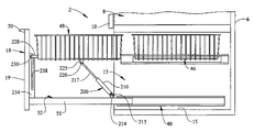
- a pneumatic lifting mechanism 195 includes a lifting member 200 that includes a cylinder portion 210 having a terminal end portion 213 . Terminal end portion 213 is pivotally connected to a bracket 214 provided on basket support wall 52 .
- Lifting member 200 also includes a piston or plunger 217 that retractably extends from within cylinder portion 210 . Plunger 217 is provided with an end portion 220 that is pivotally connected to a mounting element 225 provided on lower basket 48 .
- Mounting element 225 preferably extends substantially perpendicularly downward from a bottom wall (not separately labeled) of lower basket 48 .
- a second bracket 228 projects from a front wall portion (not separately labeled) of lower basket 48 and includes a guide member 230 in the form of a pin or roller.
- Guide member 230 transitions within a guide element 234 when lower basket 48 transitions between a lowered position, as represented in FIG. 6 , and a raised position, as represented in FIG. 7 .
- guide element 234 includes a longitudinally extending slot 238 that receives guide member 230 and terminates at an upper portion (not separately labeled) in a notch 241 .
- lifting mechanism 195 provides an assist to the consumer in raising lower basket 48 . That is, as lower basket 48 is raised, compressed gas contained within cylinder portion 216 expands, forcing plunger 217 outward. As plunger 217 moves outward, a force is applied to lower basket 48 assisting the consumer. Once lower basket 48 is in the raised position, guide member 230 nests within notch 241 preventing lower basket 48 from inadvertently shifting.
- plunger 217 shifting in cylinder portion 216 acts as a damper, preventing lower basket 48 from slamming against basket support wall 52 . More specifically, as lower basket 48 shifts downward, the compressed gas prevents plunger 217 from quickly retracting into cylinder portion 210 .
- various other mechanisms such as springs or cam operated linkages, could also be employed to soften or otherwise slow the transition from the raised position to the lowered position.
- any form of damper can be incorporated into the first embodiment of the present invention to prevent lower basket 48 from rapidly shifting from the raised position to the lower position, thereby slamming into basket support wall 52 .
- a consumer is provided with enhanced access to a lower freezer basket. That is, it should be understood that the present invention provides for a convenient means of accessing a lower basket in a bottom mount freezer compartment so as to alleviate the need for a consumer to bend over when accessing items stored in the lower freezer basket.
- the lifting mechanisms described are but three examples of mechanisms that can be employed to raise the freezer basket from its lowered position to its raised position and numerous other mechanisms can also be employed.
- the present invention could operate to automatically raise lower basket 48 upon opening freezer door 18 . That is, when a consumer opens freezer door 18 , basket 48 would automatically raise to a position corresponding to that of upper basket 46 .
- an obstacle detection sensor must be employed to ensure that the lifting mechanism does not operate in the event that there is something blocking the travel path of basket 48 .
- the invention is only to be limited to be limited by the scope of the following claims.
Abstract
Description
Claims (7)
Priority Applications (2)
| Application Number | Priority Date | Filing Date | Title |
|---|---|---|---|
| US11/489,450 US7628461B2 (en) | 2006-07-20 | 2006-07-20 | Bottom mount refrigerator having an elevating freezer basket |
| EP07252810A EP1881282A3 (en) | 2006-07-20 | 2007-07-13 | Bottom mount refrigerator having an elevating freezer basket |
Applications Claiming Priority (1)
| Application Number | Priority Date | Filing Date | Title |
|---|---|---|---|
| US11/489,450 US7628461B2 (en) | 2006-07-20 | 2006-07-20 | Bottom mount refrigerator having an elevating freezer basket |
Publications (2)
| Publication Number | Publication Date |
|---|---|
| US20080018215A1 US20080018215A1 (en) | 2008-01-24 |
| US7628461B2 true US7628461B2 (en) | 2009-12-08 |
Family
ID=38694846
Family Applications (1)
| Application Number | Title | Priority Date | Filing Date |
|---|---|---|---|
| US11/489,450 Expired - Fee Related US7628461B2 (en) | 2006-07-20 | 2006-07-20 | Bottom mount refrigerator having an elevating freezer basket |
Country Status (2)
| Country | Link |
|---|---|
| US (1) | US7628461B2 (en) |
| EP (1) | EP1881282A3 (en) |
Cited By (30)
| Publication number | Priority date | Publication date | Assignee | Title |
|---|---|---|---|---|
| US20090151380A1 (en) * | 2005-10-05 | 2009-06-18 | Seung Hwan Oh | Refrigerator |
| US20090193836A1 (en) * | 2008-02-01 | 2009-08-06 | Whirlpool Corporation | Articulated freezer drawers |
| US20110232322A1 (en) * | 2010-03-25 | 2011-09-29 | Whirlpool Corporation | Upper freezer basket guided by lower freezer basket divider |
| US20120155050A1 (en) * | 2010-12-20 | 2012-06-21 | Hon Hai Precision Industry Co., Ltd. | Electronic device having inner holder for functional module |
| US20120262044A1 (en) * | 2011-04-18 | 2012-10-18 | General Electric Company | Consumer appliance drawer with improved anti-racking system |
| DE102011053985A1 (en) * | 2011-09-27 | 2013-03-28 | Paul Hettich Gmbh & Co. Kg | fitting |
| US8702185B2 (en) * | 2012-05-08 | 2014-04-22 | General Electric Company | Refrigerator appliance with a drawer |
| US8827390B2 (en) | 2012-07-19 | 2014-09-09 | General Electric Company | Appliance with features for facilitating access to a container |
| US9282877B2 (en) | 2012-03-21 | 2016-03-15 | Whirlpool Corporation | Dishwasher with a pivot system for a dish rack |
| US9377238B2 (en) * | 2013-03-14 | 2016-06-28 | Electrolux Home Products, Inc. | Refrigerator with a scissor-type lift mechanism |
| US20160309982A1 (en) * | 2015-04-24 | 2016-10-27 | BSH Hausgeräte GmbH | Lifting device and dishwasher |
| US9510679B2 (en) | 2012-11-09 | 2016-12-06 | Ravi Nikhil Bhatt | Drawer mechanism |
| US9895046B1 (en) | 2016-12-27 | 2018-02-20 | Midea Group Co., Ltd. | Dishwasher rack lift system |
| US9915449B1 (en) * | 2015-04-12 | 2018-03-13 | Patrick Pack | Refrigerator-freezer |
| US20180168429A1 (en) * | 2015-06-22 | 2018-06-21 | BSH Hausgeräte GmbH | Lifting device and dishwasher |
| US10024593B2 (en) * | 2016-07-20 | 2018-07-17 | Adam Holm | Under counter insulated enclosure |
| US10159398B2 (en) | 2016-12-27 | 2018-12-25 | Midea Group Co., Ltd. | Dishwasher rack system |
| US10376131B2 (en) | 2015-05-11 | 2019-08-13 | BSH Hausgeräte GmbH | Dishwasher |
| US20190293345A1 (en) * | 2018-03-26 | 2019-09-26 | Lg Electronics Inc. | Refrigerator |
| US20190346199A1 (en) * | 2018-05-08 | 2019-11-14 | Lg Electronics Inc. | Refrigerator |
| US20200069055A1 (en) * | 2018-08-31 | 2020-03-05 | Lg Electronics Inc. | Refrigerator |
| US20210022496A1 (en) * | 2019-07-26 | 2021-01-28 | Haier Us Appliance Solutions, Inc. | Motorized basket lifting mechanism |
| US11105515B2 (en) * | 2017-03-03 | 2021-08-31 | Lg Electronics Inc. | Cooking apparatus |
| WO2022014896A1 (en) * | 2020-07-14 | 2022-01-20 | Samsung Electronics Co., Ltd. | Refrigerator |
| US11248837B2 (en) | 2018-08-30 | 2022-02-15 | Lg Electronics Inc. | Refrigerator |
| US11435134B2 (en) * | 2018-08-30 | 2022-09-06 | Lg Electronics Inc. | Refrigerator |
| US11573050B2 (en) * | 2018-10-19 | 2023-02-07 | Lg Electronics Inc. | Refrigerator |
| US11578909B2 (en) | 2020-05-26 | 2023-02-14 | Whirlpool Corporation | Shelf assembly for an appliance |
| US20230184483A1 (en) * | 2021-12-13 | 2023-06-15 | Electrolux Home Products, Inc. | Swing-up storage assembly |
| US11920382B2 (en) | 2020-09-15 | 2024-03-05 | Midea Group Co., Ltd. | Rotating support handle assembly for bottom-hinged door |
Families Citing this family (60)
| Publication number | Priority date | Publication date | Assignee | Title |
|---|---|---|---|---|
| KR100700777B1 (en) * | 2005-03-02 | 2007-03-27 | 엘지전자 주식회사 | Refrigerating machine and basket operating apparatus |
| US8056996B2 (en) * | 2006-09-01 | 2011-11-15 | General Electric Company | Support assembly for an appliance storage bin or storage shelf |
| KR101275562B1 (en) * | 2006-09-07 | 2013-06-17 | 엘지전자 주식회사 | A Rail-assembly for refrigerator and refrigerator comprising the same |
| KR101106645B1 (en) * | 2007-02-26 | 2012-01-20 | 삼성전자주식회사 | Refrigerator |
| KR101517231B1 (en) * | 2008-03-05 | 2015-05-04 | 엘지전자 주식회사 | Refrigerator |
| KR101380557B1 (en) * | 2008-03-26 | 2014-04-01 | 엘지전자 주식회사 | System and method for driving a drawer in a refrigerator |
| US8217613B2 (en) | 2008-03-26 | 2012-07-10 | Lg Electronics Inc. | System and method for driving a drawer of a refrigerator and refrigerator employing same |
| WO2009119924A1 (en) * | 2008-03-26 | 2009-10-01 | Lg Electronics Inc. | Refrigerator, system and method for driving a drawer of the refrigerator |
| KR101441133B1 (en) * | 2008-03-26 | 2014-09-17 | 엘지전자 주식회사 | Controlling method for driving drawer of refrigerator |
| CN101981396A (en) * | 2008-03-26 | 2011-02-23 | Lg电子株式会社 | System and method for driving a drawer in a refrigerator |
| CN101981397B (en) * | 2008-03-26 | 2013-08-21 | Lg电子株式会社 | System and method for driving a drawer in a refrigerator |
| KR101532796B1 (en) * | 2008-03-26 | 2015-07-01 | 엘지전자 주식회사 | Refrigerator |
| AT10668U1 (en) * | 2008-08-29 | 2009-08-15 | Blum Gmbh Julius | HOUSING FOR AT LEAST PARTIAL RECORDING OF A FURNITURE FITTING |
| DE102009000841A1 (en) * | 2009-02-13 | 2010-09-02 | BSH Bosch und Siemens Hausgeräte GmbH | The refrigerator |
| US8333447B2 (en) * | 2009-02-27 | 2012-12-18 | Electrolux Home Products, Inc. | Basket kick-out |
| US8220887B2 (en) * | 2009-02-27 | 2012-07-17 | Electrolux Home Products, Inc. | Selectable presentation of dual-bin system |
| KR20100101827A (en) * | 2009-03-10 | 2010-09-20 | 삼성전자주식회사 | Refrigerator |
| CN101504237A (en) * | 2009-03-12 | 2009-08-12 | 青岛澳柯玛股份有限公司 | Refrigerator with folding basket |
| KR101592573B1 (en) * | 2009-03-20 | 2016-02-05 | 엘지전자 주식회사 | A refrigerator |
| KR101592574B1 (en) * | 2009-03-20 | 2016-02-05 | 엘지전자 주식회사 | A refrigerator for controlling refrigerator |
| KR101592571B1 (en) * | 2009-03-20 | 2016-02-05 | 엘지전자 주식회사 | A refrigerator for controlling refrigerator |
| KR101592572B1 (en) * | 2009-03-20 | 2016-02-05 | 엘지전자 주식회사 | A refrigerator for controlling refrigerator |
| KR101592575B1 (en) * | 2009-03-20 | 2016-02-05 | 엘지전자 주식회사 | Refrigerator |
| KR101787095B1 (en) * | 2009-07-07 | 2017-10-18 | 엘지전자 주식회사 | Refrigerator |
| CN102226626B (en) * | 2011-04-22 | 2013-07-03 | 合肥美的荣事达电冰箱有限公司 | Control method used for refrigerator |
| DE202012012186U1 (en) * | 2012-12-20 | 2014-03-25 | Grass Gmbh | Hebesenkvorrichtung |
| US9107494B2 (en) * | 2013-03-14 | 2015-08-18 | Electrolux Home Products, Inc. | Refrigerator with a lift mechanism including at least one pivot arm |
| FR3018677B1 (en) * | 2014-03-18 | 2016-04-15 | Jacques Valdenaire | HOUSING DEVICE WITH LIFTING SYSTEM FOR HOUSEHOLD APPLIANCE, SUCH AS DISHWASHER OR DRAWER UNIT. |
| KR101610115B1 (en) * | 2014-08-01 | 2016-04-08 | 현대자동차 주식회사 | Fuel cell stack |
| KR101999268B1 (en) * | 2015-11-12 | 2019-07-12 | 삼성전자주식회사 | Dish Washing Machine |
| KR102519038B1 (en) * | 2016-06-10 | 2023-04-05 | 엘지전자 주식회사 | Refrigerator and lift up drawer for refrigerator |
| US20170370148A1 (en) * | 2016-06-24 | 2017-12-28 | Fred Smith | Drawer-Integrated Step Stool |
| EP3301739B1 (en) * | 2016-09-28 | 2019-05-15 | Toshiba Fuel Cell Power Systems Corporation | Fuel cell module |
| KR102219932B1 (en) * | 2016-11-04 | 2021-02-25 | 삼성전자주식회사 | Cooking apparatus |
| FI11506U1 (en) * | 2016-11-25 | 2017-01-13 | Toni Kuusi | Arrangement to move the luggage compartment in the closet |
| US10702125B2 (en) | 2017-09-29 | 2020-07-07 | Midea Group Co., Ltd. | Retracting dishwasher rack system |
| EP3505854B1 (en) | 2017-12-29 | 2021-08-18 | LG Electronics Inc. | Refrigerator |
| KR20190109069A (en) | 2018-03-16 | 2019-09-25 | 엘지전자 주식회사 | Refrigerator |
| KR102510856B1 (en) | 2018-03-26 | 2023-03-15 | 엘지전자 주식회사 | Refrigerator |
| KR102474913B1 (en) * | 2018-06-22 | 2022-12-06 | 엘지전자 주식회사 | Refrigerator |
| US11219350B2 (en) | 2018-12-10 | 2022-01-11 | Midea Group Co., Ltd. | Retracting dishwasher rack system |
| US10694923B1 (en) | 2018-12-10 | 2020-06-30 | Midea Group Co., Ltd. | Retracting dishwasher rack system |
| US10582828B1 (en) * | 2018-12-10 | 2020-03-10 | Midea Group Co., Ltd. | Retracting dishwasher rack system |
| CN111336763B (en) * | 2018-12-18 | 2021-06-04 | 海信(山东)冰箱有限公司 | A kind of refrigerator |
| CN111336764B (en) * | 2018-12-18 | 2021-06-04 | 海信(山东)冰箱有限公司 | A kind of refrigerator |
| CN111561803B (en) * | 2019-02-13 | 2023-01-10 | 海信冰箱有限公司 | Refrigerator with a door |
| KR102579883B1 (en) * | 2018-12-28 | 2023-09-18 | 엘지전자 주식회사 | Refrigerator |
| KR102609769B1 (en) * | 2019-01-14 | 2023-12-05 | 엘지전자 주식회사 | Refrigerator |
| CN109984492B (en) * | 2019-04-10 | 2021-06-29 | 九牧厨卫股份有限公司 | Device with automatic drawer |
| CN112146337B (en) * | 2019-06-27 | 2021-09-21 | 青岛海尔电冰箱有限公司 | Refrigerator drawer and refrigerator |
| KR20210007641A (en) | 2019-07-12 | 2021-01-20 | 엘지전자 주식회사 | Refrigerator having drawer type door |
| KR20210007646A (en) | 2019-07-12 | 2021-01-20 | 엘지전자 주식회사 | refrigerator |
| KR20210007644A (en) | 2019-07-12 | 2021-01-20 | 엘지전자 주식회사 | refrigerator |
| KR20210007639A (en) * | 2019-07-12 | 2021-01-20 | 엘지전자 주식회사 | Refrigerator |
| KR20210007647A (en) | 2019-07-12 | 2021-01-20 | 엘지전자 주식회사 | refrigerator |
| KR20210007638A (en) | 2019-07-12 | 2021-01-20 | 엘지전자 주식회사 | Refrigerator |
| KR20210007642A (en) | 2019-07-12 | 2021-01-20 | 엘지전자 주식회사 | Refrigerator having drawer type door |
| KR20210008707A (en) | 2019-07-15 | 2021-01-25 | 엘지전자 주식회사 | Refrigerator and control method thereof |
| KR20210008709A (en) | 2019-07-15 | 2021-01-25 | 엘지전자 주식회사 | Refrigerator and control method thereof |
| KR20210061708A (en) * | 2019-11-20 | 2021-05-28 | 엘지전자 주식회사 | Refrigerator |
Citations (22)
| Publication number | Priority date | Publication date | Assignee | Title |
|---|---|---|---|---|
| US1934370A (en) * | 1931-12-12 | 1933-11-07 | Pasquale A Mirabella | Filing drawer |
| US2486564A (en) * | 1945-10-03 | 1949-11-01 | Cribben And Sexton Company | Stove construction |
| US2525201A (en) * | 1947-05-23 | 1950-10-10 | John K Beynon | Door operated oven rack structure |
| US2590341A (en) * | 1946-02-23 | 1952-03-25 | Orvie E Nabholz | Filing cabinet |
| US2819141A (en) * | 1954-05-21 | 1958-01-07 | American Radiator & Standard | Cutting board drawer construction |
| US3212835A (en) * | 1962-01-16 | 1965-10-19 | Whirlpool Co | Drop down cabinet door and associated removable receptacle |
| US3862788A (en) * | 1972-04-19 | 1975-01-28 | Sperry Rand Corp | Drawer ejector device |
| US4151804A (en) * | 1977-10-31 | 1979-05-01 | Eberhard Kunze | Elevating apparatus particularly adapted for television receiver support-tables and the like |
| US4790146A (en) | 1986-03-04 | 1988-12-13 | Sam Sung Electronics Co., Ltd. | Refrigerator |
| JPH05296647A (en) * | 1992-04-14 | 1993-11-09 | Toshiba Corp | Refrigerator |
| US5908009A (en) | 1997-01-31 | 1999-06-01 | Cummings; William D. | Cattle head gate |
| US5971513A (en) * | 1998-03-19 | 1999-10-26 | Cassalia; Alan B. | Easy load extendable/retractable bottom dishwasher rack |
| US6247771B1 (en) * | 2000-08-18 | 2001-06-19 | Evelyn J. Miller | Lower rack lifting device for a dishwasher |
| JP2002264943A (en) | 2001-03-12 | 2002-09-18 | Matsushita Refrig Co Ltd | Capacity variable container and refrigerator provided with the same |
| US6641239B2 (en) * | 1998-12-07 | 2003-11-04 | BSH Bosch und Siemens Hauseräte GmbH | Refrigerating unit |
| US20040164654A1 (en) * | 2001-06-01 | 2004-08-26 | Karl-Friedrich Laible | Cold goods container for a cooling apparatus |
| US20040183415A1 (en) * | 2003-03-20 | 2004-09-23 | Lg Electronics Inc. | Drawer type door opening/closing structure of refrigerator |
| US20060022564A1 (en) * | 2004-07-29 | 2006-02-02 | Lg Electronics Inc. | Bottom drawer type refrigerator having basket lift device |
| US20060043849A1 (en) | 2004-08-26 | 2006-03-02 | Lg Electronics Inc. | Refrigerator having basket lift apparatus |
| US20060043848A1 (en) | 2004-07-29 | 2006-03-02 | Lg Electronics Inc. | Refrigerator having basket lift apparatus |
| US20060049731A1 (en) | 2004-09-07 | 2006-03-09 | Lg Electronics Inc. | Double drawer of refrigerator |
| US7232196B2 (en) | 2003-10-04 | 2007-06-19 | Lg Electronics, Inc. | Refrigerator |
Family Cites Families (3)
| Publication number | Priority date | Publication date | Assignee | Title |
|---|---|---|---|---|
| KR100398644B1 (en) * | 2001-06-26 | 2003-09-19 | 위니아만도 주식회사 | Upper And Down Type Of Kim-Chi Refrigerator |
| KR100652583B1 (en) * | 2004-07-29 | 2006-12-06 | 엘지전자 주식회사 | Refrigerator having basket lift apparatus |
| KR20060031113A (en) * | 2004-10-07 | 2006-04-12 | 엘지전자 주식회사 | Refrigerator with food lifting apparatus |
-
2006
- 2006-07-20 US US11/489,450 patent/US7628461B2/en not_active Expired - Fee Related
-
2007
- 2007-07-13 EP EP07252810A patent/EP1881282A3/en not_active Withdrawn
Patent Citations (23)
| Publication number | Priority date | Publication date | Assignee | Title |
|---|---|---|---|---|
| US1934370A (en) * | 1931-12-12 | 1933-11-07 | Pasquale A Mirabella | Filing drawer |
| US2486564A (en) * | 1945-10-03 | 1949-11-01 | Cribben And Sexton Company | Stove construction |
| US2590341A (en) * | 1946-02-23 | 1952-03-25 | Orvie E Nabholz | Filing cabinet |
| US2525201A (en) * | 1947-05-23 | 1950-10-10 | John K Beynon | Door operated oven rack structure |
| US2819141A (en) * | 1954-05-21 | 1958-01-07 | American Radiator & Standard | Cutting board drawer construction |
| US3212835A (en) * | 1962-01-16 | 1965-10-19 | Whirlpool Co | Drop down cabinet door and associated removable receptacle |
| US3862788A (en) * | 1972-04-19 | 1975-01-28 | Sperry Rand Corp | Drawer ejector device |
| US4151804A (en) * | 1977-10-31 | 1979-05-01 | Eberhard Kunze | Elevating apparatus particularly adapted for television receiver support-tables and the like |
| US4790146A (en) | 1986-03-04 | 1988-12-13 | Sam Sung Electronics Co., Ltd. | Refrigerator |
| JPH05296647A (en) * | 1992-04-14 | 1993-11-09 | Toshiba Corp | Refrigerator |
| US5908009A (en) | 1997-01-31 | 1999-06-01 | Cummings; William D. | Cattle head gate |
| US5971513A (en) * | 1998-03-19 | 1999-10-26 | Cassalia; Alan B. | Easy load extendable/retractable bottom dishwasher rack |
| US6641239B2 (en) * | 1998-12-07 | 2003-11-04 | BSH Bosch und Siemens Hauseräte GmbH | Refrigerating unit |
| US6247771B1 (en) * | 2000-08-18 | 2001-06-19 | Evelyn J. Miller | Lower rack lifting device for a dishwasher |
| JP2002264943A (en) | 2001-03-12 | 2002-09-18 | Matsushita Refrig Co Ltd | Capacity variable container and refrigerator provided with the same |
| US20040164654A1 (en) * | 2001-06-01 | 2004-08-26 | Karl-Friedrich Laible | Cold goods container for a cooling apparatus |
| US20040183415A1 (en) * | 2003-03-20 | 2004-09-23 | Lg Electronics Inc. | Drawer type door opening/closing structure of refrigerator |
| US7232196B2 (en) | 2003-10-04 | 2007-06-19 | Lg Electronics, Inc. | Refrigerator |
| US20060022564A1 (en) * | 2004-07-29 | 2006-02-02 | Lg Electronics Inc. | Bottom drawer type refrigerator having basket lift device |
| US20060043848A1 (en) | 2004-07-29 | 2006-03-02 | Lg Electronics Inc. | Refrigerator having basket lift apparatus |
| US7396093B2 (en) * | 2004-07-29 | 2008-07-08 | Lg Electronics Inc | Refrigerator having basket lift apparatus |
| US20060043849A1 (en) | 2004-08-26 | 2006-03-02 | Lg Electronics Inc. | Refrigerator having basket lift apparatus |
| US20060049731A1 (en) | 2004-09-07 | 2006-03-09 | Lg Electronics Inc. | Double drawer of refrigerator |
Cited By (58)
| Publication number | Priority date | Publication date | Assignee | Title |
|---|---|---|---|---|
| US8104852B2 (en) * | 2005-10-05 | 2012-01-31 | Lg Electronics Inc. | Refrigerator |
| US20090151380A1 (en) * | 2005-10-05 | 2009-06-18 | Seung Hwan Oh | Refrigerator |
| US20090193836A1 (en) * | 2008-02-01 | 2009-08-06 | Whirlpool Corporation | Articulated freezer drawers |
| US8231190B2 (en) * | 2008-02-01 | 2012-07-31 | Whirlpool Corporation | Articulated freezer drawers |
| US20120248958A1 (en) * | 2008-02-01 | 2012-10-04 | Whirlpool Corporation | Articulated freezer drawers |
| US8474928B2 (en) * | 2008-02-01 | 2013-07-02 | Whirlpool Corporation | Articulated freezer drawers |
| US20110232322A1 (en) * | 2010-03-25 | 2011-09-29 | Whirlpool Corporation | Upper freezer basket guided by lower freezer basket divider |
| US8671712B2 (en) * | 2010-03-25 | 2014-03-18 | Whirlpool Corporation | Upper freezer basket guided by lower freezer basket divider |
| US20120155050A1 (en) * | 2010-12-20 | 2012-06-21 | Hon Hai Precision Industry Co., Ltd. | Electronic device having inner holder for functional module |
| US8456860B2 (en) * | 2010-12-20 | 2013-06-04 | Hong Fu Jin Precision Industry (Shenzhen) Co., Ltd. | Electronic device having inner holder for functional module |
| US8931863B2 (en) * | 2011-04-18 | 2015-01-13 | General Electric Company | Consumer appliance drawer with improved anti-racking system |
| US20120262044A1 (en) * | 2011-04-18 | 2012-10-18 | General Electric Company | Consumer appliance drawer with improved anti-racking system |
| DE102011053985A1 (en) * | 2011-09-27 | 2013-03-28 | Paul Hettich Gmbh & Co. Kg | fitting |
| US9389014B2 (en) | 2011-09-27 | 2016-07-12 | Paul Hettich Gmbh & Co. Kg | Fitting |
| US10178938B2 (en) | 2012-03-21 | 2019-01-15 | Whirpool Corporation | Dishwasher with a pivot system for a dish rack |
| US10123677B2 (en) | 2012-03-21 | 2018-11-13 | Whirlpool Corporation | Dishwasher with a pivot system for a dish rack |
| US9282877B2 (en) | 2012-03-21 | 2016-03-15 | Whirlpool Corporation | Dishwasher with a pivot system for a dish rack |
| US11116380B2 (en) | 2012-03-21 | 2021-09-14 | Whirlpool Corporation | Dishwasher with a pivot system for a dish rack |
| US8702185B2 (en) * | 2012-05-08 | 2014-04-22 | General Electric Company | Refrigerator appliance with a drawer |
| US8827390B2 (en) | 2012-07-19 | 2014-09-09 | General Electric Company | Appliance with features for facilitating access to a container |
| US9510679B2 (en) | 2012-11-09 | 2016-12-06 | Ravi Nikhil Bhatt | Drawer mechanism |
| US9377238B2 (en) * | 2013-03-14 | 2016-06-28 | Electrolux Home Products, Inc. | Refrigerator with a scissor-type lift mechanism |
| US9915449B1 (en) * | 2015-04-12 | 2018-03-13 | Patrick Pack | Refrigerator-freezer |
| US20160309982A1 (en) * | 2015-04-24 | 2016-10-27 | BSH Hausgeräte GmbH | Lifting device and dishwasher |
| US10016115B2 (en) * | 2015-04-24 | 2018-07-10 | BSH Hausgeräte GmbH | Lifting device and dishwasher |
| US10376131B2 (en) | 2015-05-11 | 2019-08-13 | BSH Hausgeräte GmbH | Dishwasher |
| US20180168429A1 (en) * | 2015-06-22 | 2018-06-21 | BSH Hausgeräte GmbH | Lifting device and dishwasher |
| US10842345B2 (en) * | 2015-06-22 | 2020-11-24 | BSH Hausgeräte GmbH | Lifting device and dishwasher |
| US10024593B2 (en) * | 2016-07-20 | 2018-07-17 | Adam Holm | Under counter insulated enclosure |
| US10159398B2 (en) | 2016-12-27 | 2018-12-25 | Midea Group Co., Ltd. | Dishwasher rack system |
| US10299657B2 (en) | 2016-12-27 | 2019-05-28 | Midea Group Co., Ltd. | Dishwasher rack lift system |
| US9895046B1 (en) | 2016-12-27 | 2018-02-20 | Midea Group Co., Ltd. | Dishwasher rack lift system |
| US10433705B2 (en) | 2016-12-27 | 2019-10-08 | Midea Group Co., Ltd. | Dishwasher rack system |
| US11105515B2 (en) * | 2017-03-03 | 2021-08-31 | Lg Electronics Inc. | Cooking apparatus |
| US10598428B2 (en) * | 2018-03-26 | 2020-03-24 | Lg Electronics Inc. | Refrigerator |
| US20190293345A1 (en) * | 2018-03-26 | 2019-09-26 | Lg Electronics Inc. | Refrigerator |
| US11486634B2 (en) * | 2018-03-26 | 2022-11-01 | Lg Electronics Inc. | Refrigerator |
| US11073331B2 (en) * | 2018-03-26 | 2021-07-27 | Lg Electronics Inc. | Refrigerator |
| US10876788B2 (en) * | 2018-05-08 | 2020-12-29 | Lg Electronics Inc. | Refrigerator |
| US11898794B2 (en) | 2018-05-08 | 2024-02-13 | Lg Electronics Inc. | Refrigerator |
| US11614275B2 (en) | 2018-05-08 | 2023-03-28 | Lg Electronics Inc. | Refrigerator |
| US11047619B2 (en) | 2018-05-08 | 2021-06-29 | Lg Electronics Inc. | Refrigerator |
| US20190346199A1 (en) * | 2018-05-08 | 2019-11-14 | Lg Electronics Inc. | Refrigerator |
| US11248837B2 (en) | 2018-08-30 | 2022-02-15 | Lg Electronics Inc. | Refrigerator |
| US11435134B2 (en) * | 2018-08-30 | 2022-09-06 | Lg Electronics Inc. | Refrigerator |
| US11561040B2 (en) | 2018-08-30 | 2023-01-24 | Lg Electronics Inc. | Refrigerator |
| US11859898B2 (en) | 2018-08-30 | 2024-01-02 | Lg Electronics Inc. | Refrigerator having scissors lift for drawer |
| US20200069055A1 (en) * | 2018-08-31 | 2020-03-05 | Lg Electronics Inc. | Refrigerator |
| US10945524B2 (en) * | 2018-08-31 | 2021-03-16 | Lg Electronics Inc. | Refrigerator |
| US11573050B2 (en) * | 2018-10-19 | 2023-02-07 | Lg Electronics Inc. | Refrigerator |
| US10932568B2 (en) * | 2019-07-26 | 2021-03-02 | Haier Us Appliance Solutions, Inc. | Motorized basket lifting mechanism |
| US20210022496A1 (en) * | 2019-07-26 | 2021-01-28 | Haier Us Appliance Solutions, Inc. | Motorized basket lifting mechanism |
| US11578909B2 (en) | 2020-05-26 | 2023-02-14 | Whirlpool Corporation | Shelf assembly for an appliance |
| US11585595B2 (en) | 2020-07-14 | 2023-02-21 | Samsung Electronics Co., Ltd. | Refrigerator |
| WO2022014896A1 (en) * | 2020-07-14 | 2022-01-20 | Samsung Electronics Co., Ltd. | Refrigerator |
| US11920382B2 (en) | 2020-09-15 | 2024-03-05 | Midea Group Co., Ltd. | Rotating support handle assembly for bottom-hinged door |
| US20230184483A1 (en) * | 2021-12-13 | 2023-06-15 | Electrolux Home Products, Inc. | Swing-up storage assembly |
| US11796245B2 (en) * | 2021-12-13 | 2023-10-24 | Electrolux Home Products, Inc. | Swing-up storage assembly |
Also Published As
| Publication number | Publication date |
|---|---|
| EP1881282A3 (en) | 2011-10-26 |
| US20080018215A1 (en) | 2008-01-24 |
| EP1881282A2 (en) | 2008-01-23 |
Similar Documents
| Publication | Publication Date | Title |
|---|---|---|
| US7628461B2 (en) | Bottom mount refrigerator having an elevating freezer basket | |
| US8220887B2 (en) | Selectable presentation of dual-bin system | |
| KR102595327B1 (en) | A refrigerator | |
| KR102542609B1 (en) | Refrigerator | |
| KR20030084072A (en) | vegetable tray of refrigerator open/close structure | |
| KR102580773B1 (en) | A refrigerator | |
| EP3764042B1 (en) | Refrigerator | |
| US5947573A (en) | Refrigerator and compartment therefor | |
| US5193892A (en) | Food compartment for refrigerators | |
| US8056996B2 (en) | Support assembly for an appliance storage bin or storage shelf | |
| US20040183415A1 (en) | Drawer type door opening/closing structure of refrigerator | |
| US20050145704A1 (en) | Refrigerator | |
| KR102309146B1 (en) | drawer and refrigerator with drawer | |
| WO2008111817A1 (en) | Refrigerator and drawer opening/closing apparatus for the same | |
| AU2010218176B2 (en) | Basket kick-out | |
| EP2049853B1 (en) | A refrigerator | |
| WO2022095832A1 (en) | Drawer assembly for electric appliance, and refrigeration appliance | |
| US11592233B2 (en) | Refrigerator | |
| WO2023114065A1 (en) | Refrigerator | |
| EP1245917B1 (en) | Household refrigerating apparatus, with sliding container | |
| EP1064508A1 (en) | Storage container for use in refrigerator | |
| US20210310722A1 (en) | Refrigerator | |
| JP2004298218A (en) | Shelf device and refrigerator equipped with shelf device | |
| CN113074477B (en) | Refrigerator with a refrigerator body | |
| KR200358395Y1 (en) | Kitchen furniture |
Legal Events
| Date | Code | Title | Description |
|---|---|---|---|
| AS | Assignment |
Owner name: MAYTAG CORPORATION, IOWA Free format text: ASSIGNMENT OF ASSIGNORS INTEREST;ASSIGNORS:CARDEN, MICHAEL SCOT;SENNER, KURT C.;REEL/FRAME:018070/0645;SIGNING DATES FROM 20060424 TO 20060712 |
|
| STCF | Information on status: patent grant |
Free format text: PATENTED CASE |
|
| CC | Certificate of correction | ||
| FPAY | Fee payment |
Year of fee payment: 4 |
|
| FPAY | Fee payment |
Year of fee payment: 8 |
|
| FEPP | Fee payment procedure |
Free format text: MAINTENANCE FEE REMINDER MAILED (ORIGINAL EVENT CODE: REM.); ENTITY STATUS OF PATENT OWNER: LARGE ENTITY |
|
| LAPS | Lapse for failure to pay maintenance fees |
Free format text: PATENT EXPIRED FOR FAILURE TO PAY MAINTENANCE FEES (ORIGINAL EVENT CODE: EXP.); ENTITY STATUS OF PATENT OWNER: LARGE ENTITY |
|
| STCH | Information on status: patent discontinuation |
Free format text: PATENT EXPIRED DUE TO NONPAYMENT OF MAINTENANCE FEES UNDER 37 CFR 1.362 |
|
| FP | Lapsed due to failure to pay maintenance fee |
Effective date: 20211208 |