US7602146B2 - Protection methods, protection circuits and protection devices for secondary batteries, a power tool, charger and battery pack adapted to provide protection against fault conditions in the battery pack - Google Patents

Protection methods, protection circuits and protection devices for secondary batteries, a power tool, charger and battery pack adapted to provide protection against fault conditions in the battery pack Download PDF

Info

Publication number
US7602146B2
US7602146B2 US12/079,429 US7942908A US7602146B2 US 7602146 B2 US7602146 B2 US 7602146B2 US 7942908 A US7942908 A US 7942908A US 7602146 B2 US7602146 B2 US 7602146B2
Authority
US
United States
Prior art keywords
battery pack
cells
charger
current
battery
Prior art date
Legal status (The legal status is an assumption and is not a legal conclusion. Google has not performed a legal analysis and makes no representation as to the accuracy of the status listed.)
Active
Application number
US12/079,429
Other versions
US20080180059A1 (en
Inventor
David A. Carrier
Steven J. Phillips
Jeffrey J. Francis
R. Roby Bailey
Danh Thanh Trinh
Andrew E. Seman, Jr.
Christopher R. Yahnker
Daniele C. Brotto
Current Assignee (The listed assignees may be inaccurate. Google has not performed a legal analysis and makes no representation or warranty as to the accuracy of the list.)
Black and Decker Inc
Original Assignee
Black and Decker Inc
Priority date (The priority date is an assumption and is not a legal conclusion. Google has not performed a legal analysis and makes no representation as to the accuracy of the date listed.)
Filing date
Publication date
Application filed by Black and Decker Inc filed Critical Black and Decker Inc
Priority to US12/079,429 priority Critical patent/US7602146B2/en
Publication of US20080180059A1 publication Critical patent/US20080180059A1/en
Application granted granted Critical
Publication of US7602146B2 publication Critical patent/US7602146B2/en
Active legal-status Critical Current
Anticipated expiration legal-status Critical

Links

Images

Classifications

    • BPERFORMING OPERATIONS; TRANSPORTING
    • B25HAND TOOLS; PORTABLE POWER-DRIVEN TOOLS; MANIPULATORS
    • B25FCOMBINATION OR MULTI-PURPOSE TOOLS NOT OTHERWISE PROVIDED FOR; DETAILS OR COMPONENTS OF PORTABLE POWER-DRIVEN TOOLS NOT PARTICULARLY RELATED TO THE OPERATIONS PERFORMED AND NOT OTHERWISE PROVIDED FOR
    • B25F5/00Details or components of portable power-driven tools not particularly related to the operations performed and not otherwise provided for
    • BPERFORMING OPERATIONS; TRANSPORTING
    • B60VEHICLES IN GENERAL
    • B60LPROPULSION OF ELECTRICALLY-PROPELLED VEHICLES; SUPPLYING ELECTRIC POWER FOR AUXILIARY EQUIPMENT OF ELECTRICALLY-PROPELLED VEHICLES; ELECTRODYNAMIC BRAKE SYSTEMS FOR VEHICLES IN GENERAL; MAGNETIC SUSPENSION OR LEVITATION FOR VEHICLES; MONITORING OPERATING VARIABLES OF ELECTRICALLY-PROPELLED VEHICLES; ELECTRIC SAFETY DEVICES FOR ELECTRICALLY-PROPELLED VEHICLES
    • B60L53/00Methods of charging batteries, specially adapted for electric vehicles; Charging stations or on-board charging equipment therefor; Exchange of energy storage elements in electric vehicles
    • B60L53/10Methods of charging batteries, specially adapted for electric vehicles; Charging stations or on-board charging equipment therefor; Exchange of energy storage elements in electric vehicles characterised by the energy transfer between the charging station and the vehicle
    • B60L53/14Conductive energy transfer
    • B60L53/18Cables specially adapted for charging electric vehicles
    • HELECTRICITY
    • H01ELECTRIC ELEMENTS
    • H01MPROCESSES OR MEANS, e.g. BATTERIES, FOR THE DIRECT CONVERSION OF CHEMICAL ENERGY INTO ELECTRICAL ENERGY
    • H01M10/00Secondary cells; Manufacture thereof
    • H01M10/42Methods or arrangements for servicing or maintenance of secondary cells or secondary half-cells
    • H01M10/425Structural combination with electronic components, e.g. electronic circuits integrated to the outside of the casing
    • HELECTRICITY
    • H01ELECTRIC ELEMENTS
    • H01MPROCESSES OR MEANS, e.g. BATTERIES, FOR THE DIRECT CONVERSION OF CHEMICAL ENERGY INTO ELECTRICAL ENERGY
    • H01M10/00Secondary cells; Manufacture thereof
    • H01M10/42Methods or arrangements for servicing or maintenance of secondary cells or secondary half-cells
    • H01M10/44Methods for charging or discharging
    • H01M10/441Methods for charging or discharging for several batteries or cells simultaneously or sequentially
    • HELECTRICITY
    • H01ELECTRIC ELEMENTS
    • H01MPROCESSES OR MEANS, e.g. BATTERIES, FOR THE DIRECT CONVERSION OF CHEMICAL ENERGY INTO ELECTRICAL ENERGY
    • H01M10/00Secondary cells; Manufacture thereof
    • H01M10/42Methods or arrangements for servicing or maintenance of secondary cells or secondary half-cells
    • H01M10/44Methods for charging or discharging
    • H01M10/443Methods for charging or discharging in response to temperature
    • HELECTRICITY
    • H01ELECTRIC ELEMENTS
    • H01MPROCESSES OR MEANS, e.g. BATTERIES, FOR THE DIRECT CONVERSION OF CHEMICAL ENERGY INTO ELECTRICAL ENERGY
    • H01M10/00Secondary cells; Manufacture thereof
    • H01M10/42Methods or arrangements for servicing or maintenance of secondary cells or secondary half-cells
    • H01M10/48Accumulators combined with arrangements for measuring, testing or indicating the condition of cells, e.g. the level or density of the electrolyte
    • H01M10/482Accumulators combined with arrangements for measuring, testing or indicating the condition of cells, e.g. the level or density of the electrolyte for several batteries or cells simultaneously or sequentially
    • HELECTRICITY
    • H01ELECTRIC ELEMENTS
    • H01MPROCESSES OR MEANS, e.g. BATTERIES, FOR THE DIRECT CONVERSION OF CHEMICAL ENERGY INTO ELECTRICAL ENERGY
    • H01M10/00Secondary cells; Manufacture thereof
    • H01M10/42Methods or arrangements for servicing or maintenance of secondary cells or secondary half-cells
    • H01M10/48Accumulators combined with arrangements for measuring, testing or indicating the condition of cells, e.g. the level or density of the electrolyte
    • H01M10/486Accumulators combined with arrangements for measuring, testing or indicating the condition of cells, e.g. the level or density of the electrolyte for measuring temperature
    • HELECTRICITY
    • H01ELECTRIC ELEMENTS
    • H01MPROCESSES OR MEANS, e.g. BATTERIES, FOR THE DIRECT CONVERSION OF CHEMICAL ENERGY INTO ELECTRICAL ENERGY
    • H01M10/00Secondary cells; Manufacture thereof
    • H01M10/42Methods or arrangements for servicing or maintenance of secondary cells or secondary half-cells
    • H01M10/48Accumulators combined with arrangements for measuring, testing or indicating the condition of cells, e.g. the level or density of the electrolyte
    • H01M10/488Cells or batteries combined with indicating means for external visualization of the condition, e.g. by change of colour or of light density
    • HELECTRICITY
    • H01ELECTRIC ELEMENTS
    • H01MPROCESSES OR MEANS, e.g. BATTERIES, FOR THE DIRECT CONVERSION OF CHEMICAL ENERGY INTO ELECTRICAL ENERGY
    • H01M50/00Constructional details or processes of manufacture of the non-active parts of electrochemical cells other than fuel cells, e.g. hybrid cells
    • H01M50/20Mountings; Secondary casings or frames; Racks, modules or packs; Suspension devices; Shock absorbers; Transport or carrying devices; Holders
    • H01M50/247Mountings; Secondary casings or frames; Racks, modules or packs; Suspension devices; Shock absorbers; Transport or carrying devices; Holders specially adapted for portable devices, e.g. mobile phones, computers, hand tools or pacemakers
    • HELECTRICITY
    • H01ELECTRIC ELEMENTS
    • H01MPROCESSES OR MEANS, e.g. BATTERIES, FOR THE DIRECT CONVERSION OF CHEMICAL ENERGY INTO ELECTRICAL ENERGY
    • H01M50/00Constructional details or processes of manufacture of the non-active parts of electrochemical cells other than fuel cells, e.g. hybrid cells
    • H01M50/50Current conducting connections for cells or batteries
    • H01M50/572Means for preventing undesired use or discharge
    • H01M50/574Devices or arrangements for the interruption of current
    • H01M50/581Devices or arrangements for the interruption of current in response to temperature
    • HELECTRICITY
    • H01ELECTRIC ELEMENTS
    • H01MPROCESSES OR MEANS, e.g. BATTERIES, FOR THE DIRECT CONVERSION OF CHEMICAL ENERGY INTO ELECTRICAL ENERGY
    • H01M50/00Constructional details or processes of manufacture of the non-active parts of electrochemical cells other than fuel cells, e.g. hybrid cells
    • H01M50/50Current conducting connections for cells or batteries
    • H01M50/572Means for preventing undesired use or discharge
    • H01M50/574Devices or arrangements for the interruption of current
    • H01M50/583Devices or arrangements for the interruption of current in response to current, e.g. fuses
    • HELECTRICITY
    • H02GENERATION; CONVERSION OR DISTRIBUTION OF ELECTRIC POWER
    • H02JCIRCUIT ARRANGEMENTS OR SYSTEMS FOR SUPPLYING OR DISTRIBUTING ELECTRIC POWER; SYSTEMS FOR STORING ELECTRIC ENERGY
    • H02J7/00Circuit arrangements for charging or depolarising batteries or for supplying loads from batteries
    • H02J7/0013Circuit arrangements for charging or depolarising batteries or for supplying loads from batteries acting upon several batteries simultaneously or sequentially
    • H02J7/0014Circuits for equalisation of charge between batteries
    • HELECTRICITY
    • H02GENERATION; CONVERSION OR DISTRIBUTION OF ELECTRIC POWER
    • H02JCIRCUIT ARRANGEMENTS OR SYSTEMS FOR SUPPLYING OR DISTRIBUTING ELECTRIC POWER; SYSTEMS FOR STORING ELECTRIC ENERGY
    • H02J7/00Circuit arrangements for charging or depolarising batteries or for supplying loads from batteries
    • H02J7/0029Circuit arrangements for charging or depolarising batteries or for supplying loads from batteries with safety or protection devices or circuits
    • H02J7/00304Overcurrent protection
    • HELECTRICITY
    • H02GENERATION; CONVERSION OR DISTRIBUTION OF ELECTRIC POWER
    • H02JCIRCUIT ARRANGEMENTS OR SYSTEMS FOR SUPPLYING OR DISTRIBUTING ELECTRIC POWER; SYSTEMS FOR STORING ELECTRIC ENERGY
    • H02J7/00Circuit arrangements for charging or depolarising batteries or for supplying loads from batteries
    • H02J7/0029Circuit arrangements for charging or depolarising batteries or for supplying loads from batteries with safety or protection devices or circuits
    • H02J7/00306Overdischarge protection
    • HELECTRICITY
    • H02GENERATION; CONVERSION OR DISTRIBUTION OF ELECTRIC POWER
    • H02JCIRCUIT ARRANGEMENTS OR SYSTEMS FOR SUPPLYING OR DISTRIBUTING ELECTRIC POWER; SYSTEMS FOR STORING ELECTRIC ENERGY
    • H02J7/00Circuit arrangements for charging or depolarising batteries or for supplying loads from batteries
    • H02J7/0029Circuit arrangements for charging or depolarising batteries or for supplying loads from batteries with safety or protection devices or circuits
    • H02J7/00308Overvoltage protection
    • HELECTRICITY
    • H02GENERATION; CONVERSION OR DISTRIBUTION OF ELECTRIC POWER
    • H02JCIRCUIT ARRANGEMENTS OR SYSTEMS FOR SUPPLYING OR DISTRIBUTING ELECTRIC POWER; SYSTEMS FOR STORING ELECTRIC ENERGY
    • H02J7/00Circuit arrangements for charging or depolarising batteries or for supplying loads from batteries
    • H02J7/0029Circuit arrangements for charging or depolarising batteries or for supplying loads from batteries with safety or protection devices or circuits
    • H02J7/00309Overheat or overtemperature protection
    • HELECTRICITY
    • H02GENERATION; CONVERSION OR DISTRIBUTION OF ELECTRIC POWER
    • H02JCIRCUIT ARRANGEMENTS OR SYSTEMS FOR SUPPLYING OR DISTRIBUTING ELECTRIC POWER; SYSTEMS FOR STORING ELECTRIC ENERGY
    • H02J7/00Circuit arrangements for charging or depolarising batteries or for supplying loads from batteries
    • H02J7/0029Circuit arrangements for charging or depolarising batteries or for supplying loads from batteries with safety or protection devices or circuits
    • H02J7/0031Circuit arrangements for charging or depolarising batteries or for supplying loads from batteries with safety or protection devices or circuits using battery or load disconnect circuits
    • HELECTRICITY
    • H01ELECTRIC ELEMENTS
    • H01MPROCESSES OR MEANS, e.g. BATTERIES, FOR THE DIRECT CONVERSION OF CHEMICAL ENERGY INTO ELECTRICAL ENERGY
    • H01M2200/00Safety devices for primary or secondary batteries
    • H01M2200/10Temperature sensitive devices
    • H01M2200/106PTC
    • HELECTRICITY
    • H01ELECTRIC ELEMENTS
    • H01MPROCESSES OR MEANS, e.g. BATTERIES, FOR THE DIRECT CONVERSION OF CHEMICAL ENERGY INTO ELECTRICAL ENERGY
    • H01M50/00Constructional details or processes of manufacture of the non-active parts of electrochemical cells other than fuel cells, e.g. hybrid cells
    • H01M50/20Mountings; Secondary casings or frames; Racks, modules or packs; Suspension devices; Shock absorbers; Transport or carrying devices; Holders
    • H01M50/204Racks, modules or packs for multiple batteries or multiple cells
    • H01M50/207Racks, modules or packs for multiple batteries or multiple cells characterised by their shape
    • H01M50/213Racks, modules or packs for multiple batteries or multiple cells characterised by their shape adapted for cells having curved cross-section, e.g. round or elliptic
    • HELECTRICITY
    • H01ELECTRIC ELEMENTS
    • H01MPROCESSES OR MEANS, e.g. BATTERIES, FOR THE DIRECT CONVERSION OF CHEMICAL ENERGY INTO ELECTRICAL ENERGY
    • H01M6/00Primary cells; Manufacture thereof
    • H01M6/42Grouping of primary cells into batteries
    • YGENERAL TAGGING OF NEW TECHNOLOGICAL DEVELOPMENTS; GENERAL TAGGING OF CROSS-SECTIONAL TECHNOLOGIES SPANNING OVER SEVERAL SECTIONS OF THE IPC; TECHNICAL SUBJECTS COVERED BY FORMER USPC CROSS-REFERENCE ART COLLECTIONS [XRACs] AND DIGESTS
    • Y02TECHNOLOGIES OR APPLICATIONS FOR MITIGATION OR ADAPTATION AGAINST CLIMATE CHANGE
    • Y02EREDUCTION OF GREENHOUSE GAS [GHG] EMISSIONS, RELATED TO ENERGY GENERATION, TRANSMISSION OR DISTRIBUTION
    • Y02E60/00Enabling technologies; Technologies with a potential or indirect contribution to GHG emissions mitigation
    • Y02E60/10Energy storage using batteries
    • YGENERAL TAGGING OF NEW TECHNOLOGICAL DEVELOPMENTS; GENERAL TAGGING OF CROSS-SECTIONAL TECHNOLOGIES SPANNING OVER SEVERAL SECTIONS OF THE IPC; TECHNICAL SUBJECTS COVERED BY FORMER USPC CROSS-REFERENCE ART COLLECTIONS [XRACs] AND DIGESTS
    • Y02TECHNOLOGIES OR APPLICATIONS FOR MITIGATION OR ADAPTATION AGAINST CLIMATE CHANGE
    • Y02TCLIMATE CHANGE MITIGATION TECHNOLOGIES RELATED TO TRANSPORTATION
    • Y02T10/00Road transport of goods or passengers
    • Y02T10/60Other road transportation technologies with climate change mitigation effect
    • Y02T10/70Energy storage systems for electromobility, e.g. batteries
    • YGENERAL TAGGING OF NEW TECHNOLOGICAL DEVELOPMENTS; GENERAL TAGGING OF CROSS-SECTIONAL TECHNOLOGIES SPANNING OVER SEVERAL SECTIONS OF THE IPC; TECHNICAL SUBJECTS COVERED BY FORMER USPC CROSS-REFERENCE ART COLLECTIONS [XRACs] AND DIGESTS
    • Y02TECHNOLOGIES OR APPLICATIONS FOR MITIGATION OR ADAPTATION AGAINST CLIMATE CHANGE
    • Y02TCLIMATE CHANGE MITIGATION TECHNOLOGIES RELATED TO TRANSPORTATION
    • Y02T10/00Road transport of goods or passengers
    • Y02T10/60Other road transportation technologies with climate change mitigation effect
    • Y02T10/7072Electromobility specific charging systems or methods for batteries, ultracapacitors, supercapacitors or double-layer capacitors
    • YGENERAL TAGGING OF NEW TECHNOLOGICAL DEVELOPMENTS; GENERAL TAGGING OF CROSS-SECTIONAL TECHNOLOGIES SPANNING OVER SEVERAL SECTIONS OF THE IPC; TECHNICAL SUBJECTS COVERED BY FORMER USPC CROSS-REFERENCE ART COLLECTIONS [XRACs] AND DIGESTS
    • Y02TECHNOLOGIES OR APPLICATIONS FOR MITIGATION OR ADAPTATION AGAINST CLIMATE CHANGE
    • Y02TCLIMATE CHANGE MITIGATION TECHNOLOGIES RELATED TO TRANSPORTATION
    • Y02T90/00Enabling technologies or technologies with a potential or indirect contribution to GHG emissions mitigation
    • Y02T90/10Technologies relating to charging of electric vehicles
    • Y02T90/12Electric charging stations
    • YGENERAL TAGGING OF NEW TECHNOLOGICAL DEVELOPMENTS; GENERAL TAGGING OF CROSS-SECTIONAL TECHNOLOGIES SPANNING OVER SEVERAL SECTIONS OF THE IPC; TECHNICAL SUBJECTS COVERED BY FORMER USPC CROSS-REFERENCE ART COLLECTIONS [XRACs] AND DIGESTS
    • Y02TECHNOLOGIES OR APPLICATIONS FOR MITIGATION OR ADAPTATION AGAINST CLIMATE CHANGE
    • Y02TCLIMATE CHANGE MITIGATION TECHNOLOGIES RELATED TO TRANSPORTATION
    • Y02T90/00Enabling technologies or technologies with a potential or indirect contribution to GHG emissions mitigation
    • Y02T90/10Technologies relating to charging of electric vehicles
    • Y02T90/14Plug-in electric vehicles

Definitions

  • a lower impedance electrical source could cause damage to a tool's motor when the tool is held at stall condition.
  • the motor and battery impedances are the only mechanisms to limit the current since there is no back-EMF created by the motor. With a lower impedance pack, the currents would be higher. Higher currents through the motor will increase the likelihood of de-magnetization of the permanent magnets within the tool's motor.
  • start-up of the tool could produce excessive starting currents and cause demagnetization of the motor.
  • Thermal overload could also be a result of using a low impedance electrical source in an existing power tool, as the new batteries may be designed to run longer and harder than what the original cordless tool system was designed.
  • FIG. 3A is a block diagram illustrating components and connections between an exemplary battery pack and an exemplary battery charger in accordance with an exemplary embodiment of the present invention.
  • FIG. 3B is a block diagram illustrating components and connections between an exemplary battery pack and an exemplary power tool in accordance with an exemplary embodiment of the present invention.
  • FIG. 5 is a partial block diagram of connections between a battery pack and charger to illustrate over-charge protection in accordance with another exemplary embodiment of the present invention.
  • FIG. 6 is a graph of voltage versus time to illustrate an automatic shutdown for over-discharge protection invoked by a protection circuit in accordance with an exemplary embodiment of the present invention.
  • FIG. 10 illustrates a connection arrangement for a thermistor in accordance with an exemplary embodiment of the present invention.
  • FIG. 12 is a block diagram illustrating an exemplary arrangement for determining SOC and varying motor current switching frequency in accordance with an exemplary embodiment of the present invention.
  • FIG. 13A is an isometric view of a single laminate battery cell.
  • FIGS. 15A and 15B illustrate a device for protecting against an overcharge condition in accordance with another exemplary embodiment of the present invention.
  • a system of cordless power tools constructed in accordance with the teachings of exemplary embodiments of the present invention is illustrated.
  • Exemplary cordless power tools of the system are shown to include, by way of examples, a circular power saw 10 ( FIG. 17 ), a reciprocating saw 20 ( FIG. 18 ) and a drill 30 ( FIG. 19 ).
  • the tools 10 , 20 and 30 each may include a conventional DC motor (not shown) adapted to be powered by a power source having a given nominal voltage rating.
  • the tools 10 , 20 and 30 may be driven by a removable power source having a nominal voltage rating of at least 18 volts.
  • the teachings of the present invention may be applicable to virtually any type of cordless power tool and any supply voltage.
  • the removable power source which may be embodied as a battery pack 40 .
  • the battery pack may be a rechargeable battery pack 40 .
  • Battery pack 40 may include a plurality of battery cells connected in series, and/or a plurality of serially-connected strings of cells, in which the strings are in parallel with one another.
  • battery pack 40 may be composed of cells having a lithium-ion cell chemistry.
  • the nominal voltage rating of the battery pack 40 may be at least 18V.
  • a thermistor is a term used to describe a range of electronic components whose principle characteristic is that their electrical resistance changes in response to changes in their temperature, a ‘thermally sensitive resistor’.
  • Thermistors may be further classified as ‘Positive Temperature Coefficient’ devices (PTC devices) or ‘Negative Temperature Coefficient’ devices (NTC devices).
  • PTC devices are devices whose resistance increases as their temperature increases.
  • NTC devices are devices whose resistance decreases as their temperature increases.
  • NTC thermistors are typically manufactured from proprietary formulations of ceramic materials based on transition metal oxides.
  • FIG. 2 illustrates a partial block diagram of a protection circuit arrangement in accordance with another exemplary embodiment of the present invention.
  • An alternative approach to using multiple protection devices 102 is to include a dedicated protection circuit 210 for each cell that senses one or more battery pack parameter in a pack such as battery pack 40 , for example. These parameters include, but are not limited to current, temperature, voltage and impedance through the pack.
  • a protection circuit 210 may be operatively connected to a corresponding driver circuit 220 .
  • the level-shifting circuits 220 may be connected to a plurality of AND gates (shown by box 230 ) to link the protection circuit(s) 210 to a master device 240 which performs a current limiting or current interrupting function.
  • Pack 100 may further be composed of cells of another lithium-based chemistry, such as lithium metal or lithium polymer, or other chemistry such as nickel cadmium (NiCd), nickel metal hydride (NiMH) and lead-acid, for example, in terms of the chemistry makeup of individual cells, electrodes and electrolyte of the pack 100 .
  • another lithium-based chemistry such as lithium metal or lithium polymer
  • other chemistry such as nickel cadmium (NiCd), nickel metal hydride (NiMH) and lead-acid, for example, in terms of the chemistry makeup of individual cells, electrodes and electrolyte of the pack 100 .
  • the pack 100 may also include a Pack ID 110 connected to an output terminal (terminal 1 ) for identification of the pack 100 when inserted into a charger 150 .
  • the Pack ID 110 may include the model number, version, cell configuration and the battery type (chemistry), such as lithium-ion, NiCd or NiMH, for example.
  • the Pack ID 110 may be embodied as one or more communication codes received from output terminal 1 of the battery pack 100 by an asynchronous full duplex communication system in the pack 100 , such as is described in U.S. Pat. No. 5,680,027 to Hiratsuka et al.
  • pack ID 110 may also be embodied by an ID resistor, LED display that displays identification data of the pack, serial data sent upon engagement and sensed by the tool/charger via terminal 2 for example, and/or a field in an frame of data sent over an air interface to the tool/charger, etc.
  • a battery electronic control unit 125 may be responsible for the protection of the cells 105 for any fault condition exposed on the terminals by the user (via charger 150 , an attached tool, and/or due to user tampering).
  • the battery electronic control unit 125 may be embodied in hardware or software as a digital microcontroller, a microprocessor or an analog circuit, a digital signal processor or by one or more digital ICs such as application specific integrated circuits (ASICs), for example.
  • ASICs application specific integrated circuits
  • the discharge current and charge current can be clamped or discontinued by the use of semiconductor devices 130 a (discharge FET) and 130 b (charge FET), under the control of battery electronic control unit 125 .
  • the battery electronic control unit 125 may be powered by an internal power supply 135 as shown, and the semiconductor devices 130 a and 130 b may be linked through a driver circuit 140 .
  • Battery pack 100 may further include a current sensor 145 which senses current and provides a signal to battery electronic control unit 125 .
  • Current sensor 145 may be embodied as known components for current sensors, such as a shunt resistor, current transformer, etc. which may provide a signal representing sensed current in pack 100 to battery electronic control unit 125 .
  • Semiconductor devices 130 a may include a pull down resistor 147 which acts to bypass the semiconductor device 130 a when device 130 a is off and the pack 100 is dormant.
  • protection circuit 210 may include at least battery electronic control unit 125 , current sensor 145 , a voltage monitor circuit 115 and temperature sensor 120 , and optionally may further include pack ID 110 and an internal power supply such as power supply 135 .
  • Driver circuit 140 may be analogous to driver circuit 220 in FIG. 2 and semiconductor devices 130 a and 130 b may singly or together represent a master device 240 having a current limiting/interrupting functionality under the control of the protection circuit 210 .
  • the driver circuit 140 level shifts the PWM output of battery electronic control unit 125 to drive the gate of semiconductor device 130 a , cycling the semiconductor devices 130 a on and off depending on sensed conditions. Since the semiconductor device 130 b is reverse-biased, the device 130 b passes current with only a diode drop in voltage. If the current were at 20 Amps and device 130 b had a forward voltage of 0.6 Volts the power loss would be only 12 watts. If lower losses are desired, the battery electronic circuit 125 may output a state to the driver circuit 140 which commands the semiconductor device 130 b to remain on during the PWM action on semiconductor device 130 a . Now, the power lost into device 130 b would be its on resistance time the current squared (I 2 R ON ). Today's MOSFETs typically have an on-resistance (R ON ) of 10 milliohms, so at 20 Amps the power loss would only be 4 watts. The result is a controlled discharge and lower losses through the semiconductor device.
  • R ON on-
  • Semiconductor device 130 a is reversed-biased with respect to current flow and even though it conducts in the OFF state, device 130 a should remain ON for the least amount of losses.
  • Semiconductor device 130 b may control the charge current based on information from the battery electronic control 125 going through the driver circuit 140 .
  • the component arrangement that comprises driver circuit 140 is known in the art and is not described herein for reasons of brevity.
  • FIG. 3B is a block diagram illustrating components and connections between an exemplary battery pack and an exemplary power tool in accordance with an exemplary embodiment of the present invention.
  • FIG. 3B is merely an exemplary circuit configuration and is provided as a context for more clearly describing the various protection methods, circuits and devices in accordance with the exemplary embodiments.
  • the battery pack and tool configuration of FIG. 3B may be applicable to the exemplary cordless tool systems, and equivalents, in any of FIGS. 17-19 .
  • Tool 170 may include a tool electronic control unit 180 .
  • Tool electronic control unit 180 may also be embodied in hardware or software as a digital microcontroller, microprocessor, analog circuit, digital signal processor, or by one or more digital ICs such as application specific integrated circuits (ASICs), for example.
  • ASICs application specific integrated circuits
  • the tool electronic control unit 180 may be programmable so as to read a trigger position of a trigger 181 and report the trigger position to the battery electronic control unit 125 via serial data paths at terminals 4 and 5 . Based on the trigger position data, the battery electronic control unit 125 may vary the PWM duty cycle through semiconductor device 130 a to obtain the desired motor speed in tool motor 190 . While semiconductor device 130 a is off, a diode 195 in the tool 170 may re-circulate residual inductive motor current to prevent voltage spikes from occurring therein.
  • the forward/reversing switch 185 is typical for cordless tools and will not be described here.
  • a conventional hardware watchdog circuit is typically located in the charger. This circuit monitors the charge current and looks for a 10 ms current off reset pulse in the charging current. In a typical charging scenario, a microprocessor in the charger (such as charger electronic control unit 155 ) may generate this reset pulse using the charge control line I CTRL . In an abnormal situation (e.g., the charger microprocessor has locked the current solid on or the charger power supply has locked the current solid on), the hardware watchdog circuit would timeout and turn the charge current off using a charge FET. However, in the conventional arrangement, it is still possible to overcharge the battery pack if the microprocessor in the charger were to continually generate the reset pulse without ever terminating the fast charge (due to improper microprocessor behavior, for example).
  • battery pack 100 includes at least a battery electronic control unit 125 , semiconductor device 130 b (such as charge control FET) and temperature sensor 120 .
  • the temperature sensor 120 may be embodied as an internal NTC thermistor, for example.
  • the charger 150 may include at least charger electronic control circuit 155 , a charge FET 157 and a hardware watchdog circuit 158 .
  • the battery electronic control unit 125 may receive a battery temperature value from the internal NTC thermistor and may communicate this information via serial data paths at terminals 3 and/or 4 to the charger electronic control unit 155 .
  • the charge current may be terminated by the battery electronic control circuit 125 sending a PWM control signal or pulse, via driver circuit 140 , to turn semiconductor device 130 b off.
  • this control signal may be sent via serial data paths at terminals 3 and/or 4 to charger electronic control circuit 155 to turn off the charge FET 157 in the charger 150 .
  • watchdog 158 The dotted arrowhead lines in FIG. 4 show a hardware watchdog circuit 158 (hereafter watchdog 158 ) having multiple reset inputs. In addition to monitoring the charge current reset pulse, watchdog 158 also monitors the serial communications clock path (through terminal 3 ) as a reset pulse. If any of these reset pulses did not occur, the watchdog would timeout and turn the charge current off. It may still be possible to overcharge the battery pack 100 in the event of a 2 point failure—a shorted charge control FET (e.g., device 130 b ) in the battery pack 100 and improper unit behavior in one of the battery electronic control unit 125 or charger electronic control unit 155 .
  • a shorted charge control FET e.g., device 130 b
  • watchdog 158 could also monitor the battery stack voltage using voltage monitor circuit 415 B and terminal 7 to sense an overvoltage condition which would indicate an overcharge condition.
  • a shorted battery charge control FET semiconductor device 130 b
  • any failures in the battery electronic control unit 125 or charger electronic control unit 155 would not affect the watchdog's 158 ability to monitor the battery stack voltage for sensing and terminating an overcharge condition.
  • voltage monitor circuit 415 B used for monitoring the battery stack voltage could also directly control the charge FET in the battery ( 130 b ) (see optional dotted line 425 ) through the driver circuit ( 140 ) and/or directly control the charge FET in the charger ( 157 ) through the AND logic ( 151 ) and terminal ( 7 ). This control would allow voltage monitor circuit 415 B to stop an overcharge condition due to overvoltage of the entire battery stack voltage.
  • FIG. 5 is a partial block diagram of connections between a battery pack and charger of a cordless power tool system to illustrate over-charge protection in accordance with another exemplary embodiment of the present invention.
  • FIG. 5 omits the voltage monitor circuits 415 A and 415 B for purposes of clarity, it being understood that both individual cell voltage and total stack voltage could be inputs to a hardware watchdog circuit 158 ′ in FIG. 5 , similar to as shown in FIG. 4 .
  • FIG. 5 is a hybrid of FIG. 4 to illustrate a watchdog 158 ′ with multiple inputs.
  • Watchdog 158 ′ monitors the charge reset pulse, clock reset pulse, and the NTC signal, cell voltage, and/or battery stack voltage in order to sense a charge lock-on condition.
  • the charge current could still be shut off even with a shorted charge control FET 130 b in the battery and improper unit behavior in one of the battery electronic control unit 125 or charger electronic control unit 155 , and may reduce the number of terminals needed by sharing the NTC output terminal with the clock terminal.
  • the exemplary hardware watchdog circuit(s) in FIGS. 4 and 5 may prevent battery overcharging by monitoring the condition of both the battery pack 100 and charger 150 . Overcharge prevention remains available even in the event of a two-point failure such as a shorted battery charge FET and improper microprocessor behavior in one (or both) of the battery pack 100 and charger 150 .
  • Determination of an over-charge fault condition can also be done by other means. If an accurate current measurement is made by a current sensor in the battery pack (such as current sensor 145 ) during discharge, then a coulomb measurement could be made by the battery electronic control unit 125 to put back in the amount of energy taken out. This could be used in conjunction with or without the voltage measurement that may be made by a protection circuit 210 in the battery pack 100 to detect an over-charge fault condition.
  • the battery pack 100 may include circuitry to prevent current flow when the battery voltage drops below a given voltage threshold, hence under-voltage lockout.
  • a protection circuit 210 in the battery pack can sense battery voltage and if the voltage drops below a given voltage level, the discharge FET (semiconductor device 130 a ) is turned off. Battery cells 105 would still be susceptible to charge, but would not discharge any more.
  • the threshold may be an absolute threshold set at time of manufacture, for example, or a threshold that may vary based on a number of given factors.
  • FIG. 7 is a graph of voltage versus time to illustrate a modified threshold for over-discharge protection in accordance with an exemplary embodiment of the present invention.
  • the protection current 210 of FIG. 2 or the battery electronic control 125 could be configured to make the following calculations and/or perform the automatic shutdown.
  • FIG. 7 shows an example of a battery pack at 10% state-of-charge. By adding in a proportion of discharge current to compensate for the impedance of the battery pack 100 , the battery pack 100 is still above a given discharge threshold of 2.7 volts.
  • a simple fuse as shown in FIG. 8A may be designed to limit the current through the cells 105 , but may also cause permanent damage once its rating is exceeded.
  • Other devices such as Positive Temperature Coefficient (PTC) elements and re-settable fuses may be substituted for the fuse in FIG. 8A for over-current protection.
  • PTC devices or elements are known as protective elements for controlling the current which flows through circuits to be protected, since their resistance value increases as they give off heat in over-current conditions.
  • PTC thermistors have been used as an over-current protection element. When an electronic circuit gets overloaded, conductive polymers of a PTC thermistor, which have PTC properties, emit heat and thermally expand to become high resistance, thereby reducing the current in the circuit to a safe, relatively small current level.
  • current sensing measures such as current sensor 145 of FIGS. 3A and 3B
  • a semiconductor device such as semiconductor devices 130 a and 130 b
  • current sensor 145 may be adapted to sense pack current to generate a control signal based on sensed current exceeding a given current limit or threshold.
  • a semiconductor device having a current limiting or current interrupting function e.g., semiconductor devices 130 a and 130 b
  • the semiconductor device may be adapted to limit or interrupt current based on the control signal received directly from the current sensor 145 instead of from battery electronic control 125 via driver 140 .
  • Current sensing could also be coupled with an averaging algorithm if momentarily high current loads were acceptable but steady state high current was not acceptable.
  • a suitable current limit or threshold could also be variable, and proportional, to the temperature of the cells. This may be beneficial in that, if the cells were already hot, the-maximum current pulled out would not be sufficient to overheat the internal cell chemistry.
  • a battery temperature threshold may be set to shutdown the battery pack until it cools below a desired or given temperature.
  • a battery temperature threshold may be set to shutdown the battery pack until it rises above a desired or given temperature.
  • These thresholds can also be based on a set limit with a partial dependence on current, voltage, age, and rate of rise or fall in temperature, for example.
  • one or more temperature sensors may be used for determining the state of the battery pack temperature.
  • FIG. 9 illustrates a device providing over-temperature protection in accordance with the exemplary embodiments of the present invention.
  • An over-temperature fault condition in a battery cell may cause permanent damage.
  • a protection circuit configured to monitor absolute temperature may be useful in preventing over-temperature conditions.
  • FIG. 9 illustrates only a portion of a battery pack circuit for reasons of brevity. However, the devices in FIG. 9 could be part of the battery pack 100 as shown in any of FIGS. 3A-5 .
  • both under-voltage and temperature limitations can be used as a cut-off, i.e., the battery pack 100 ceases to output current once a threshold is reached.
  • a warning mechanism in either the battery pack or tool may warn the operator that the operator is approaching an impending operating limit in the pack that may automatically shutdown battery power in the pack.
  • the warning mechanism could be audible (with a horn or buzzer) or visible using a desired illumination scheme such as LEDs, for example.
  • the audible and/or visible warning mechanism may be tied into the existing circuitry in the pack 100 or too 170 .
  • the battery pack 100 , tool 170 or charger 150 in any of FIGS. 3A through 5 may be controlled by intelligence in the pack, tool, charger, etc.
  • Such intelligence as battery electronic control 125 or tool electronic control 180 could be configured to control warning mechanisms for various impending or present fault conditions.
  • An additional method for alerting the user of an impending fault condition would be to vary the motor control's pulse width modulation (PWM) to create a “warble” effect in the speed of the motor. This mild cyclic change in motor speed is selected as such it would not adversely affect tool performance. This method provides the user with both audible and tactile feedback on the impending fault condition.
  • PWM pulse width modulation
  • any of the above warning mechanisms could potentially enhance the tool functionality or extend tool and/or battery pack life.
  • the following details the latter warning mechanism as directed to providing the aforementioned warbling effect in the motor of the power tool based on a state of charge in the battery pack.
  • the purpose of the PWM State of Charge (SOC) Indicator is to alert the operator of an impending fault condition which could cause automatic battery power shutdown, resulting in a ‘dead’ battery pack. This may be accomplished by directly determining SOC information in a motor control unit that is part of the battery pack circuitry. Based on the SOC information, a motor control unit in the battery pack would vary the motor current switching frequency to produce the ‘warbling effect’ in the tool motor that may be heard and/or physically felt by the tool operator.
  • SOC State of Charge
  • FIG. 11 is a flow diagram illustrating a method of alerting an operator of a power tool of an impending fault condition in the battery pack.
  • a motor control unit (not shown) in the battery pack may measure various battery pack parameters to determine state of charge (SOC) information in the battery pack at a given time instant (S 1110 ).
  • the motor control unit may be embodied in hardware or software as a digital microcontroller or microprocessor or an analog circuit, for example, and/or by a digital IC such as a digital signal processor or an application specific integrated circuit (ASIC). Based on the SOC information, the motor control unit determines a desired motor current switching frequency (S 1120 ) which is imparted to the tool motor to produce the warbling effect (S 1130 ) to alert the operator.
  • SOC state of charge
  • the motor current switching frequency for the tool 170 motor could be manipulated in a number of ways to alert the user. Accordingly, adjusting the motor current switching frequency enables the motor of the tool to communicate to the tool operator.
  • a switching frequency could be selected in the audible frequency range, so that the motor would make a noise that is perceptible by the operator.
  • Exemplary audible frequencies could be a constant frequency tone emitted by the tool motor, a varying frequency ring tone, a complex series of multiple frequency tones to mimic a ‘voice’ speaking to the tool operator, for example.
  • the motor control unit could pulse the motor so as to make the tool physically shutter or vibrate in a way that would let the operator know that the battery packing was running out of charge, for example, or approaching a fault condition requiring attention.
  • Methods of pulse-width-modulating the motor to alert the operator of an impending fault condition could also be used to communicate other fault conditions.
  • motor current switching frequency could be adjusted to alert the tool operator based on sensed information related to an over temperature condition in the battery pack, over temperature condition in the tool motor, over-current condition in the pack and/or under-voltage condition due to an excessive amount of current being drawn from the battery pack.
  • Current, temperature and voltage are merely exemplary measurable parameters that could be tracked for a given fault condition.
  • FIG. 12 is a block diagram illustrating an exemplary arrangement for determining SOC and varying motor current switching frequency in accordance with an exemplary embodiment of the present invention.
  • FIG. 12 shows a circuit interface relationship between battery pack 100 ′ and tool 170 ′ somewhat similar to FIG. 3B , although only certain components are shown for reasons of clarity.
  • Motor control unit IC 2 drives the gates of Q 5 and Q 6 (which may be embodied as MOSFETs) in order to regulate output voltage of the battery pack and thereby control motor current that powers the motor M 1 of the tool.
  • IC 2 may measure one of more battery pack parameters to determine SOC. For example, IC 2 could monitor battery pack output voltage across nodes N 1 and N 2 , or perform Coulomb counting by monitoring current at shunt resistor R 5 and keeping track of time (via suitable internal clock). Further, IC 2 could also monitor pack impedance by subtracting loaded battery pack output voltage (when current is flowing) from unloaded pack voltage (recorded before current draw) and dividing the result by the current measurement taken at R 5 . Any of these measurable parameters could serve as a SOC measure. IC 2 would then use this SOC information to determine the appropriate switching frequency, and control Q 5 and Q 6 to achieve that switching frequency.
  • FIGS. 13-16 in general, illustrate various devices for providing overcharge protection in extreme cases.
  • an overcharge condition fails to be addressed by the above described watchdog circuit of FIGS. 4 and 5 , other current sensory devices, and/or an intelligent device microprocessor in one or more of the battery pack 100 or charger 150 fails (multi-point failures in pack or charger),
  • FIGS. 13-16 illustrate potential secondary protection for the battery pack 100 and/or charger 150 .
  • FIGS. 13B and 13C illustrate a device which may reduce the potential for battery cells having a lithium-ion cell chemistry (or other cell chemistries) from rupturing upon a severe overcharge condition that is unattended by other protection circuitry in the pack.
  • the laminated lithium-ion battery cells 1305 may exhibit extensive swelling. If the overcharge continues, this may result in a rupture of one or more of the cells 1305 . This rupture may result in fire and potentially severe damage to the battery pack 100 attached electrical device (charger 150 , tool 170 ) and/or user of the battery pack 100 .
  • the charger lead wire or trace 1505 is connected to pack lead wire at contacts 1405 , 1505 .
  • charger lead wire 1505 abuts an inside surface a charger housing sidewall 1501 .
  • Plunger 1408 and spring 1410 are as described in FIG. 14A .
  • FIG. 16B showing one cell 1305 in an overcharged state. As the cell 1305 expands, the expansion force from the cell assists the plunger 1408 in overcoming the counterforce spring pressure from spring 1410 . Thus, plunger 1408 travels into recess 1409 to sever charger lead wire 1505 as shown generally at 1615 , thereby interrupting charge current to the cells 1405 of the battery pack.
  • the swelling cell 1305 also causes the tabs 1303 to come apart as shown generally at 1308 , providing further redundancy to sever or break the electrical connections internal to the battery pack. These protective features may thus prevent rupture of one or more cells in the pack 100 by interrupting the current flow.

Abstract

In a cordless power tool system, protection methods, circuits and devices are provided to protect against fault conditions within a battery pack that is operatively attached to a power tool or charger, so as to prevent internal or external damage to the battery pack or attached tool or charger. The exemplary methods, circuits and devices address fault conditions such as over-charge, over-discharge, over-current, over-temperature, etc.

Description

CROSS-REFERENCE TO RELATED APPLICATIONS
This application is a divisional of U.S. patent application Ser. No. 10/959,193 filed on Oct. 7, 2004 which claims the benefit of U.S. Provisional Application No. 60/510,128, filed on Oct. 14, 2003 and U.S. Provisional Application No. 60/551,803, filed on Mar. 11, 2004. The entire contents of the disclosures for each of these applications are incorporated herein by reference.
BACKGROUND OF THE INVENTION
1. Field of the Invention
The present invention relates to protection methods, protection circuits and protective devices for rechargeable batteries, to a power tool and charger adapted to provide protection for cells of an attached battery pack, and to a battery pack including protection control therein, each protecting the battery back against various potential fault conditions.
2. Description of Related Art
Over the past few years, lithium-ion (Li-ion) batteries have begun replacing nickel-cadmium (NiCd), nickel-metal-hydride (NiMH), and lead-acid batteries in low-voltage, portable electronic devices such as notebook-type personal computers. As compared to NiCd and NiMH batteries, Li-ion batteries are lighter but have a larger capacity per unit volume. For this reason, the Li-ion batteries have been typically suitable to low-voltage devices that are preferably light and which are required to endure continuous use for a long time. In an over-discharged state, however, the Li-ion batteries deteriorate rapidly, thus Li-ion batteries require over-discharge protection.
A battery pack used in a portable electronic device typically has a plurality of battery cells connected in series. The maximum number of battery cells connected in series in one battery pack is determined by the output voltage of the battery pack. For instance, the typical output voltage of one NiCd battery cell or one NiMH battery cell is 1.2 V. Assuming that an 18V output voltage from a battery pack is suitable for most general purpose electronic devices, the maximum number of NiCd or NiMH battery cells connected in series in the battery pack is 15. On the other hand, the typical output voltage of one Li-ion battery cell is approximately 3.6 V. Accordingly, the maximum number of Li-ion battery cells connected in series in one fictional 18V Li-ion battery pack would be 5.
Unlike a NiCd battery pack and a NiMH battery pack, the Li-ion battery pack may include functionality to protect against fault conditions inside and outside the Li-ion battery pack. This prevents cells in the Li-ion battery pack from deteriorating and shortening useful life of the pack. For instance, if a fault condition such as short-circuiting occurs inside or outside the Li-ion battery, a fuse may be provided to cut off an over-discharging current or an overcharging current, if the discharging current or charging current becomes larger than a given current level.
Currently, protection circuits in battery packs such as Li-ion battery packs are designed primarily for low-voltage portable electronic devices such as notebook-type personal computers, cellular phones, etc., which require voltage generally on the order of 2 to 4 volts. Such devices are characterized by using battery packs composed of cells (such as Li-ion, NiCd, NiMH cells) that provide a maximum output voltage of about 4.2 volts/cell. For Li-ion battery cells, care must be taken to prevent damage from electrical and mechanical stresses, since lithium is a highly reactive substance.
Conventional protection circuits for these low-voltage battery packs may monitor cell voltages to prevent a given cell from over-charging or over-discharging, and may monitor current to keep current from rising too high. Other protection circuits may have one or more temperature inputs to disable current during charge or discharge until the battery pack cools down. Still other protection circuits may be designed to help maintain the balance of charge on the cells, commonly known as equalization circuits. A typical protection circuit may be connected to a given battery cell or group of cells in the battery pack to avoid these situations. For example, a conventional protection circuit may typically include a pair of MOSFET's or other semiconductors that can stop current flow in either direction.
However, much higher voltages than described above are required for higher-power electronic devices such as cordless power tools. Accordingly, higher-power battery packs may be in the process of being developed for cordless power tools. Such “high-power” battery packs may provide higher voltage outputs than conventional NiCd and NiMH battery packs (and substantially higher power than conventional Li-ion packs used for PCs and cell phones), and at a much reduced weight (as compared to conventional NiCd or NiMH battery packs used as power sources in conventional cordless power tools). A characteristic of these battery packs is that the battery packs may exhibit substantially lower impedance characteristics than conventional NiCd, NiMH and/or even the lower power Li-ion packs.
Further, as these battery technologies advance, the introduction of lower impedance chemistries and construction styles to develop secondary batteries generating substantially higher output voltages (of at least 18 V and up, for example) may possibly create several additional protection issues. Battery packs having lower impedance also means that the pack can supply substantially higher current to an attached electronic component, such as a power tool. As current through a motor of the attached power tool increases, demagnetization forces (e.g., the number of armature turns of the motor times the current, ampere-turns) could substantially increase beyond a desired or design limit in the motor. Such undesirable demagnetization could thus potentially burn up the motor.
For example, a lower impedance electrical source could cause damage to a tool's motor when the tool is held at stall condition. During motor stall, the motor and battery impedances are the only mechanisms to limit the current since there is no back-EMF created by the motor. With a lower impedance pack, the currents would be higher. Higher currents through the motor will increase the likelihood of de-magnetization of the permanent magnets within the tool's motor.
Additionally, start-up of the tool could produce excessive starting currents and cause demagnetization of the motor. Thermal overload could also be a result of using a low impedance electrical source in an existing power tool, as the new batteries may be designed to run longer and harder than what the original cordless tool system was designed.
Accordingly, different protection controls may need to be in place to address potential fault conditions that could occur in high power battery packs that are adapted for use with both existing cordless power tools, and developing lines of power tools that are manufactured for use with these higher power battery packs. In particular, protection controls need to be developed to handle fault conditions such as over-charge, over-discharge, over-current, over-temperature and cell imbalance which could occur in one or more cells of a battery pack (such as a Li-ion or NiCd pack), so as to prevent internal or external damage to the pack, an attached device such as a charger or tool or to a user in the vicinity of a pack connected to a charger or tool.
SUMMARY OF THE INVENTION
In a cordless power tool system including a battery pack, exemplary embodiments of the present invention are directed to protection methods, protection arrangements and/or devices designed to protect against fault conditions in the battery pack operatively attached to the power tool or charger, so as to prevent internal or external damage to the battery pack or attached tool or charger. The exemplary methods, circuits and devices address fault conditions in the battery pack such as over-charge, over-discharge, over-current, over-temperature, etc.
BRIEF DESCRIPTION OF THE DRAWINGS
The exemplary embodiments of the present invention will become more fully understood from the detailed description given herein below and the accompanying drawings, wherein like elements are represented by like reference numerals, which are given by way of illustration only and thus are not limitative of the exemplary embodiments of the present invention.
FIG. 1 illustrates a partial block diagram of a protection circuit arrangement in accordance with an exemplary embodiment of the present invention.
FIG. 2 illustrates a partial block diagram of a protection circuit arrangement in accordance with another exemplary embodiment of the present invention.
FIG. 3A is a block diagram illustrating components and connections between an exemplary battery pack and an exemplary battery charger in accordance with an exemplary embodiment of the present invention.
FIG. 3B is a block diagram illustrating components and connections between an exemplary battery pack and an exemplary power tool in accordance with an exemplary embodiment of the present invention.
FIG. 4 is a partial block diagram of connections between a battery pack and charger to illustrate over-charge protection in accordance with an exemplary embodiment of the present invention.
FIG. 5 is a partial block diagram of connections between a battery pack and charger to illustrate over-charge protection in accordance with another exemplary embodiment of the present invention.
FIG. 6 is a graph of voltage versus time to illustrate an automatic shutdown for over-discharge protection invoked by a protection circuit in accordance with an exemplary embodiment of the present invention.
FIG. 7 is a graph of voltage versus time to illustrate a modified threshold for over-discharge protection in accordance with an exemplary embodiment of the present invention.
FIGS. 8A and 8B illustrate exemplary devices used for over-current protection in accordance with an exemplary embodiment of the present invention.
FIG. 9 illustrates a device providing over-temperature protection in accordance with the exemplary embodiments of the present invention.
FIG. 10 illustrates a connection arrangement for a thermistor in accordance with an exemplary embodiment of the present invention.
FIG. 11 is a flow diagram illustrating a method of alerting an operator of a power tool of an impending fault condition in the battery pack.
FIG. 12 is a block diagram illustrating an exemplary arrangement for determining SOC and varying motor current switching frequency in accordance with an exemplary embodiment of the present invention.
FIG. 13A is an isometric view of a single laminate battery cell.
FIGS. 13B and 13C illustrate a device for protecting against an overcharge condition in accordance with an exemplary embodiment of the present invention.
FIGS. 14A and 14B illustrate a device for protecting against an overcharge condition in accordance with another exemplary embodiment of the present invention.
FIGS. 15A and 15B illustrate a device for protecting against an overcharge condition in accordance with another exemplary embodiment of the present invention.
FIGS. 16A and 16B illustrate a device for protecting against an overcharge condition in accordance with another exemplary embodiment of the present invention.
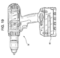
FIGS. 17-19 illustrate exemplary cordless power tools of a cordless power tool system in accordance with an exemplary embodiment of the present invention.
DETAILED DESCRIPTION OF THE EXEMPLARY EMBODIMENTS
With general reference to the drawings, a system of cordless power tools constructed in accordance with the teachings of exemplary embodiments of the present invention is illustrated. Exemplary cordless power tools of the system are shown to include, by way of examples, a circular power saw 10 (FIG. 17), a reciprocating saw 20 (FIG. 18) and a drill 30 (FIG. 19). The tools 10, 20 and 30 each may include a conventional DC motor (not shown) adapted to be powered by a power source having a given nominal voltage rating. In the exemplary embodiments, the tools 10, 20 and 30 may be driven by a removable power source having a nominal voltage rating of at least 18 volts. It will become evident to those skilled that the present invention is not limited to the particular types of tools shown in the drawings nor to specific voltages. In this regard, the teachings of the present invention may be applicable to virtually any type of cordless power tool and any supply voltage.
With continued reference to the drawings, the removable power source which may be embodied as a battery pack 40. In the exemplary embodiments illustrated, the battery pack may be a rechargeable battery pack 40. Battery pack 40 may include a plurality of battery cells connected in series, and/or a plurality of serially-connected strings of cells, in which the strings are in parallel with one another. For purposes of describing the exemplary embodiments of the present invention, battery pack 40 may be composed of cells having a lithium-ion cell chemistry. As the exemplary embodiments are directed to the cordless power tool environment, which requires power sources having much higher voltage ratings than conventional low voltage devices using Li-ion battery technology, (such as laptop computers and cellular phones) the nominal voltage rating of the battery pack 40 may be at least 18V.
However, pack 40 may be composed of cells of another lithium-based chemistry, such as lithium metal or lithium polymer, or other chemistry such as nickel cadmium (NiCd), nickel metal hydride (NiMH) and lead-acid, for example, in terms of the chemistry makeup of individual cells, electrodes and electrolyte of the pack 40.
FIG. 1 illustrates a partial block diagram of a protection circuit arrangement in accordance with an exemplary embodiment of the present invention. FIG. 1 illustrates a portion of a battery circuit and in particular illustrates an individual protection device 102 for each cell 105 of a battery pack such as battery pack 40 in FIGS. 17-19. In FIG. 1, each protection device 102 may be adapted to perform a current limiting function. In an example, the protection devices 102 may be embodied as thermistor devices, where a thermistor device is part of or contained inside the cell.
A thermistor is a term used to describe a range of electronic components whose principle characteristic is that their electrical resistance changes in response to changes in their temperature, a ‘thermally sensitive resistor’. Thermistors may be further classified as ‘Positive Temperature Coefficient’ devices (PTC devices) or ‘Negative Temperature Coefficient’ devices (NTC devices). PTC devices are devices whose resistance increases as their temperature increases. NTC devices are devices whose resistance decreases as their temperature increases. NTC thermistors are typically manufactured from proprietary formulations of ceramic materials based on transition metal oxides.
In FIG. 1, the protection devices 102 may be embodied as PTC devices, which may protect the string of cells from thermal overload. If any cell becomes hot, the PTC device within that cell increases in resistance to limit the current through the entire string. This method of protection of battery cells may have a drawback in that it requires many devices (PTC's in this example) performing a current limiting function as protection device 102.
FIG. 2 illustrates a partial block diagram of a protection circuit arrangement in accordance with another exemplary embodiment of the present invention. An alternative approach to using multiple protection devices 102 is to include a dedicated protection circuit 210 for each cell that senses one or more battery pack parameter in a pack such as battery pack 40, for example. These parameters include, but are not limited to current, temperature, voltage and impedance through the pack. A protection circuit 210 may be operatively connected to a corresponding driver circuit 220. The level-shifting circuits 220 may be connected to a plurality of AND gates (shown by box 230) to link the protection circuit(s) 210 to a master device 240 which performs a current limiting or current interrupting function. If any protection circuit detects a problem it can change from an output high to an output low state. The AND gates ensure that all protection circuit outputs are high (OK) to turn master device 240 on. Additionally, it is envisioned that the reverse logic could be used with the protection devices output to be normally low and using NOR gates instead. The master device 240 may be embodied as semiconductor device such as a metal-oxide semiconductor field effect transistor (MOSFET), as shown in FIG. 2. Accordingly, if a battery pack has multiple cells 105 in series, then an exemplary configuration envisions a set of protection circuits 210 (apportioned one per cell) connected to and controlling a master device 240 that enables/disables current flow, such as a MOSFET.
As discussed above, using multiple, dedicated protection circuits 210 may require a corresponding level-shifting circuit 220 that drops the voltage changes from the highest potential cells down to normal levels to switch the master semiconductor device 240, as shown in FIG. 2 for example. If monitoring each cell is excessive, then groups of cells or the entire battery pack may be monitored with a single protection circuit 210 and a single master device 240 for limiting or interrupting current.
FIG. 3A is a block diagram illustrating components and connections between an exemplary battery pack and an exemplary battery charger in accordance with an exemplary embodiment of the present invention. FIG. 3A is merely an exemplary circuit configuration and is provided as a context for more clearly describing the various protection methods, circuits and devices in accordance with the exemplary embodiments.
Referring to FIG. 3A, battery pack 100 may include a plurality of battery cells 105 connected in series (six shown for simplicity, pack 100 could include more or less than six cells or may be composed of serial strings of cells with the serial strings in parallel with each other). For purposes of describing the exemplary embodiments of battery pack 100 may be composed of cells having a lithium-ion cell chemistry. As the exemplary embodiments are directed to the cordless power tool environment, which requires much higher voltage ratings than conventional devices using Li-ion battery technology, the nominal voltage rating of the battery pack 100 may be at least 18V.
Thus, battery pack 100 in FIG. 3A (and in FIG. 3B) may be applicable to and/or designed for cordless power tool systems comprising at least a cordless power tool, the battery pack and a charger. Pack 100 may be understood as a removable power source for high-power, power tool operations. In an example, battery pack 100 may have a nominal voltage rating of at least 18 volts and/or have a maximum power output of at least about 385 Watts. However, it should be evident to those skilled in the art that the present invention is not necessarily limited to the particular types of tools shown in FIGS. 17-19 nor to specific voltage ratings and/or power output specifications described above.
Pack 100 may further be composed of cells of another lithium-based chemistry, such as lithium metal or lithium polymer, or other chemistry such as nickel cadmium (NiCd), nickel metal hydride (NiMH) and lead-acid, for example, in terms of the chemistry makeup of individual cells, electrodes and electrolyte of the pack 100.
In FIG. 3A, seven terminal (terminals 1-7) are shown. However, the exemplary embodiments should not be limited to this terminal configuration, as more or less terminals could be included depending on the desired information passed between, or parameters monitored by, the pack 100 or charger 150.
The pack 100 may also include a Pack ID 110 connected to an output terminal (terminal 1) for identification of the pack 100 when inserted into a charger 150. The Pack ID 110 may include the model number, version, cell configuration and the battery type (chemistry), such as lithium-ion, NiCd or NiMH, for example. The Pack ID 110 may be embodied as one or more communication codes received from output terminal 1 of the battery pack 100 by an asynchronous full duplex communication system in the pack 100, such as is described in U.S. Pat. No. 5,680,027 to Hiratsuka et al. However, this is only one example, as the pack ID 110 may also be embodied by an ID resistor, LED display that displays identification data of the pack, serial data sent upon engagement and sensed by the tool/charger via terminal 2 for example, and/or a field in an frame of data sent over an air interface to the tool/charger, etc.
The pack 100 may further include one or more temperature sensors 120. Temperature sensor 120 may be embodied as NTC or PTC thermistors, Temperature sensing Integrated Circuits, or thermocouples. The temperature sensor 120 may communicate the temperature inside the battery pack 100 to intelligence in the battery pack 100 and/or to intelligence in a connected charger 150, for example, via terminal 3. As the function of such temperature sensors are known, a detailed explanation of functional operation is omitted for purposes of brevity. Power connections for charging and discharging are represented as terminals 1 and 7.
A battery electronic control unit 125 may be responsible for the protection of the cells 105 for any fault condition exposed on the terminals by the user (via charger 150, an attached tool, and/or due to user tampering). The battery electronic control unit 125 may be embodied in hardware or software as a digital microcontroller, a microprocessor or an analog circuit, a digital signal processor or by one or more digital ICs such as application specific integrated circuits (ASICs), for example.
The discharge current and charge current can be clamped or discontinued by the use of semiconductor devices 130 a (discharge FET) and 130 b (charge FET), under the control of battery electronic control unit 125. The battery electronic control unit 125 may be powered by an internal power supply 135 as shown, and the semiconductor devices 130 a and 130 b may be linked through a driver circuit 140.
Battery pack 100 may further include a current sensor 145 which senses current and provides a signal to battery electronic control unit 125. Current sensor 145 may be embodied as known components for current sensors, such as a shunt resistor, current transformer, etc. which may provide a signal representing sensed current in pack 100 to battery electronic control unit 125. Semiconductor devices 130 a may include a pull down resistor 147 which acts to bypass the semiconductor device 130 a when device 130 a is off and the pack 100 is dormant.
Pack 100 may also include a voltage monitor circuit 115. Voltage monitor circuit 115 may be embodied by any known voltage monitor circuit, for example, and may be configured to sense individual cell voltage and/or sense total pack voltage of the string of cells 105 (‘stack voltage’) to provide a signal representing the individual cell or stack voltage to battery electronic control unit 125. As a variant, and instead of a single voltage monitor circuit 115 configured to sense both individual cell and total stack voltage, pack 100 could include a voltage monitor circuit as shown in FIG. 3A, comprising a first plurality of voltage monitor circuits (shown generally as 115A) for sensing individual cell voltage and a second voltage monitor circuit 115B for sensing total stack voltage of the cells 110, for example.
Referring back to FIG. 2, for example, protection circuit 210 may include at least battery electronic control unit 125, current sensor 145, a voltage monitor circuit 115 and temperature sensor 120, and optionally may further include pack ID 110 and an internal power supply such as power supply 135. Driver circuit 140 may be analogous to driver circuit 220 in FIG. 2 and semiconductor devices 130 a and 130 b may singly or together represent a master device 240 having a current limiting/interrupting functionality under the control of the protection circuit 210.
Referring to FIG. 3A, during discharge, the battery electronic control unit 125 may output pulse width modulation (PWM) control signals to drive the driver circuit 140. For example, a pulsing semiconductor (pulse width modulator (PWM)) is commonly used in the electronics industry to create an average voltage that is proportional to the duty cycle. PWM is modulation in which the duration of pulses is varied in accordance with some characteristic of the modulating signal. Alternatively pulse frequency modulation could be used to create this average voltage. In either case, the semiconductor devices 130 a and 130 b (which may be embodied as a discharge FET and charge FET respectively) may be switched between ON and OFF states to create an average voltage that is proportional to the duty cycle at which it is switched.
During discharge, the driver circuit 140 level shifts the PWM output of battery electronic control unit 125 to drive the gate of semiconductor device 130 a, cycling the semiconductor devices 130 a on and off depending on sensed conditions. Since the semiconductor device 130 b is reverse-biased, the device 130 b passes current with only a diode drop in voltage. If the current were at 20 Amps and device 130 b had a forward voltage of 0.6 Volts the power loss would be only 12 watts. If lower losses are desired, the battery electronic circuit 125 may output a state to the driver circuit 140 which commands the semiconductor device 130 b to remain on during the PWM action on semiconductor device 130 a. Now, the power lost into device 130 b would be its on resistance time the current squared (I2RON). Today's MOSFETs typically have an on-resistance (RON) of 10 milliohms, so at 20 Amps the power loss would only be 4 watts. The result is a controlled discharge and lower losses through the semiconductor device.
During charge, the reverse logic can be applied. Semiconductor device 130 a is reversed-biased with respect to current flow and even though it conducts in the OFF state, device 130 a should remain ON for the least amount of losses. Semiconductor device 130 b may control the charge current based on information from the battery electronic control 125 going through the driver circuit 140. The component arrangement that comprises driver circuit 140 is known in the art and is not described herein for reasons of brevity.
When battery pack 100 is connected to charger 150, a charger electronic control unit 155 in the charger 150 may be powered from the battery's internal power supply 135 through terminals 1 and 6. This is only an exemplary connection scheme, as other means for powering the charger electronic control unit 155 can be employed. The charger 150 could have its own supply or derive it directly from the battery voltage. The charger electronic control unit 155 may also be embodied in hardware or software as a digital microcontroller, microprocessor, analog circuit, digital signal processor, or by one or more digital ICs such as application specific integrated circuits (ASICs), for example. Battery and charger data and control information may be exchanged through serial data paths on terminals 4 and 5. The charger electronic control unit 155 may drive a power controller 160 with a set voltage and a set current to deliver the desired voltage and current from a power source 165 to the battery pack 100 via terminals 1 and 7.
FIG. 3B is a block diagram illustrating components and connections between an exemplary battery pack and an exemplary power tool in accordance with an exemplary embodiment of the present invention. FIG. 3B is merely an exemplary circuit configuration and is provided as a context for more clearly describing the various protection methods, circuits and devices in accordance with the exemplary embodiments. The battery pack and tool configuration of FIG. 3B may be applicable to the exemplary cordless tool systems, and equivalents, in any of FIGS. 17-19. In FIG. 3B, a ‘smart’ power tool 170 is illustrated, it being understood that battery pack 100 may be adapted for powering a ‘dumb’ power tool, i.e., a power tool without an intelligent device or microelectronic component control such as a microprocessor.
Referring to FIG. 3B, power tool 170 may be powered from the internal battery power supply 135 via terminals 1 and 6. The tool 170 may include a mechanical switch 175 that pulls terminal 7 high when the semiconductor device 130 a (discharge FET) is off. If semiconductor device 130 a is left off while the battery pack 100 is dormant, the voltage at terminal 7 is low because of the pull down resistor 147. This resistor value should have a substantially high resistance since it acts to bypass the semiconductor device 130 a. With this pull down resistor 147 in place and the semiconductor device 130 a in the off state, the voltage at terminal 7 remains low until a switch 175 in tool 170 is activated. The result is that power terminal 7 immediately increases in voltage and the signal through power terminal 7 could be used to wake the battery pack 100 from a dormant mode of operation. Tool 170 may include a tool electronic control unit 180. Tool electronic control unit 180 may also be embodied in hardware or software as a digital microcontroller, microprocessor, analog circuit, digital signal processor, or by one or more digital ICs such as application specific integrated circuits (ASICs), for example.
The tool electronic control unit 180 may be programmable so as to read a trigger position of a trigger 181 and report the trigger position to the battery electronic control unit 125 via serial data paths at terminals 4 and 5. Based on the trigger position data, the battery electronic control unit 125 may vary the PWM duty cycle through semiconductor device 130 a to obtain the desired motor speed in tool motor 190. While semiconductor device 130 a is off, a diode 195 in the tool 170 may re-circulate residual inductive motor current to prevent voltage spikes from occurring therein. The forward/reversing switch 185 is typical for cordless tools and will not be described here.
A dumb tool (not shown) may just have a trigger 181 configured as a potentiometer and connected to one of terminals 1, 4 or 5, and to terminal 6. The battery electronic control unit 125 may recognize the lack of serial data communications and perform an analog analysis of the voltage at terminals 4 or 5. Based on the analysis, the battery electronic control unit 125 may send PWM control signals via driver circuit 140 to cause semiconductor device 130 a to switch at the desired duty cycle, so as to create an intended motor speed. Even dumber tools could exist as on/off tools. These tools require only the connection to terminals 1 and 7 for operation.
Over-charge Protection
There are two basic types of battery chargers used for recharging battery packs: trickle chargers and fast chargers. Trickle chargers are significantly less expensive than fast chargers; however a trickle charger requires approximately a ½ day for recharging a battery pack. A fast charger can recharge a battery pack within about an hour. An over-charge fault condition may occur because of some fault conditioner system failure in either the charger or battery pack. Typically, a protection circuit in the battery pack can detect an over-charge fault condition by monitoring voltage across the battery pack. During charge, the voltage reaches a particular threshold. The charger thus considers the battery pack ‘fully charged’ and the charge current is terminated. If the charger was locked-on due to a component failure, it is desirable for the battery pack to be able to disable the charging current with its own semiconductor device, such as charge FET (semiconductor device 130 b) under the control of battery electronic control unit 125.
Over-charge control may be provided by use of a charge lock-on detection circuit (also known as a ‘hardware watchdog circuit’) between the battery pack and the charger. In general, if the charger locked-on and pulsing data (e.g., a clock provided from pack to charger via a suitable serial data path) stopped, then the hardware watchdog may automatically turn off the current flow.
A conventional hardware watchdog circuit is typically located in the charger. This circuit monitors the charge current and looks for a 10 ms current off reset pulse in the charging current. In a typical charging scenario, a microprocessor in the charger (such as charger electronic control unit 155) may generate this reset pulse using the charge control line ICTRL. In an abnormal situation (e.g., the charger microprocessor has locked the current solid on or the charger power supply has locked the current solid on), the hardware watchdog circuit would timeout and turn the charge current off using a charge FET. However, in the conventional arrangement, it is still possible to overcharge the battery pack if the microprocessor in the charger were to continually generate the reset pulse without ever terminating the fast charge (due to improper microprocessor behavior, for example).
FIG. 4 is a partial block diagram of connections between a battery pack and charger to illustrate over-charge protection in accordance with an exemplary embodiment of the present invention. In FIG. 4 seven terminals and six battery cells are shown for convenience, it being understood that more or less terminals and battery cells could be illustrated in the exemplary embodiment.
In FIG. 4, battery pack 100 includes at least a battery electronic control unit 125, semiconductor device 130 b (such as charge control FET) and temperature sensor 120. The temperature sensor 120 may be embodied as an internal NTC thermistor, for example. The charger 150 may include at least charger electronic control circuit 155, a charge FET 157 and a hardware watchdog circuit 158.
The battery electronic control unit 125 may receive a battery temperature value from the internal NTC thermistor and may communicate this information via serial data paths at terminals 3 and/or 4 to the charger electronic control unit 155. In the event of an extreme battery temperature due to an overcharge condition, the charge current may be terminated by the battery electronic control circuit 125 sending a PWM control signal or pulse, via driver circuit 140, to turn semiconductor device 130 b off. Alternatively, this control signal may be sent via serial data paths at terminals 3 and/or 4 to charger electronic control circuit 155 to turn off the charge FET 157 in the charger 150. However, it may still be possible to overcharge the battery pack 100 in the event of a two-point failure—a shorted semiconductor device 130 b (charge control FET) in the battery pack 100 and improper unit behavior in one of the battery electronic control unit 125 or charger electronic control unit 155.
The dotted arrowhead lines in FIG. 4 show a hardware watchdog circuit 158 (hereafter watchdog 158) having multiple reset inputs. In addition to monitoring the charge current reset pulse, watchdog 158 also monitors the serial communications clock path (through terminal 3) as a reset pulse. If any of these reset pulses did not occur, the watchdog would timeout and turn the charge current off. It may still be possible to overcharge the battery pack 100 in the event of a 2 point failure—a shorted charge control FET (e.g., device 130 b) in the battery pack 100 and improper unit behavior in one of the battery electronic control unit 125 or charger electronic control unit 155.
In addition to monitoring the charge current reset pulse, watchdog 158 also monitors the pack temperature at temperature sensor 120 (such as an NTC thermistor) directly to sense an overcharge condition. In FIG. 4, a shorted battery charge control FET (semiconductor device 130 b) and any failures in the battery electronic control unit 125 or charger electronic control unit 155 would not affect the watchdog's 158 ability to monitor the pack temperature for sensing and terminating an overcharge condition.
In addition to monitoring the charge current reset pulse, watchdog 158 could also monitor the individual cell voltages using circuits 415A and terminal 6 to sense an over voltage condition which would indicate an overcharge condition. In FIG. 4, a shorted battery charge control FET (semiconductor device 130 b) and any failures in the battery electronic control unit 125 or charger electronic control unit 155 would not affect the watchdog's 158 ability to monitor the individual cell voltages for sensing and terminating an overcharge condition.
In addition to controlling the hardware watchdog, the voltage monitor circuits 415A used for monitoring the individual cell voltages could also directly control the charge FET 130 b in the battery pack 100 through the driver circuit 140 and/or directly control the charge FET in the charger (157) through the AND logic (151) and terminal 6. This is shown by the dotted lines between voltage monitor circuits 415A and driver circuit 140. This control would allow circuits 415A to stop an overcharge condition due to overvoltage of the individual cells.
In addition to monitoring the charge current reset pulse, watchdog 158 could also monitor the battery stack voltage using voltage monitor circuit 415B and terminal 7 to sense an overvoltage condition which would indicate an overcharge condition. In FIG. 4, a shorted battery charge control FET (semiconductor device 130 b) and any failures in the battery electronic control unit 125 or charger electronic control unit 155 would not affect the watchdog's 158 ability to monitor the battery stack voltage for sensing and terminating an overcharge condition.
In addition to controlling the hardware watchdog, voltage monitor circuit 415B used for monitoring the battery stack voltage could also directly control the charge FET in the battery (130 b) (see optional dotted line 425) through the driver circuit (140) and/or directly control the charge FET in the charger (157) through the AND logic (151) and terminal (7). This control would allow voltage monitor circuit 415B to stop an overcharge condition due to overvoltage of the entire battery stack voltage.
FIG. 5 is a partial block diagram of connections between a battery pack and charger of a cordless power tool system to illustrate over-charge protection in accordance with another exemplary embodiment of the present invention. FIG. 5 omits the voltage monitor circuits 415A and 415B for purposes of clarity, it being understood that both individual cell voltage and total stack voltage could be inputs to a hardware watchdog circuit 158′ in FIG. 5, similar to as shown in FIG. 4.
FIG. 5 is a hybrid of FIG. 4 to illustrate a watchdog 158′ with multiple inputs. Watchdog 158′ monitors the charge reset pulse, clock reset pulse, and the NTC signal, cell voltage, and/or battery stack voltage in order to sense a charge lock-on condition. The charge current could still be shut off even with a shorted charge control FET 130 b in the battery and improper unit behavior in one of the battery electronic control unit 125 or charger electronic control unit 155, and may reduce the number of terminals needed by sharing the NTC output terminal with the clock terminal. Accordingly, the exemplary hardware watchdog circuit(s) in FIGS. 4 and 5 may prevent battery overcharging by monitoring the condition of both the battery pack 100 and charger 150. Overcharge prevention remains available even in the event of a two-point failure such as a shorted battery charge FET and improper microprocessor behavior in one (or both) of the battery pack 100 and charger 150.
Determination of an over-charge fault condition can also be done by other means. If an accurate current measurement is made by a current sensor in the battery pack (such as current sensor 145) during discharge, then a coulomb measurement could be made by the battery electronic control unit 125 to put back in the amount of energy taken out. This could be used in conjunction with or without the voltage measurement that may be made by a protection circuit 210 in the battery pack 100 to detect an over-charge fault condition.
Over-Discharge Protection
Various battery technologies can be damaged when discharged in excess of the manufacturer's recommendations. In accordance with the exemplary embodiments, the battery pack 100, such as is shown above in FIG. 3A or 3B, may include circuitry to prevent current flow when the battery voltage drops below a given voltage threshold, hence under-voltage lockout. A protection circuit 210 in the battery pack can sense battery voltage and if the voltage drops below a given voltage level, the discharge FET (semiconductor device 130 a) is turned off. Battery cells 105 would still be susceptible to charge, but would not discharge any more. The threshold may be an absolute threshold set at time of manufacture, for example, or a threshold that may vary based on a number of given factors.
FIG. 6 is a graph of voltage versus time to illustrate an automatic shutdown invoked by a protection circuit in accordance with an exemplary embodiment of the present invention. To protect against an over-discharge fault condition in a battery pack of a cordless power tool system, an exemplary protection circuit 210 (such as shown in FIG. 2) and/or the battery electronic control 125 in FIGS. 3A-5, could perform an automatic shutdown of current in pack 100 if the voltage reached a given threshold.
An improvement to the aforementioned voltage threshold may be to combine the threshold with a proportion of discharge current to compensate for the impedance of the battery pack 100. Basing the threshold on an absolute level and subtracting a portion of the instant current may provide an alternative method for under-voltage lockout.
FIG. 7 is a graph of voltage versus time to illustrate a modified threshold for over-discharge protection in accordance with an exemplary embodiment of the present invention. For the purposes of describing FIG. 7, the protection current 210 of FIG. 2 or the battery electronic control 125 could be configured to make the following calculations and/or perform the automatic shutdown. FIG. 7 shows an example of a battery pack at 10% state-of-charge. By adding in a proportion of discharge current to compensate for the impedance of the battery pack 100, the battery pack 100 is still above a given discharge threshold of 2.7 volts.
For example, if a 10 amp pulse load is placed on the battery pack 100, the battery impedance would cause the voltage to jump below the threshold momentarily and return to its resting value when the current pulse is removed. Even though the battery pack 100 had 10% of charge left, a protection current would have interrupted current flow. However, if the low-voltage threshold was partially compensated with current as described in the previous paragraph, the threshold would be dropped during the heavy current draw and no shutdown would occur. In other words, the low-voltage threshold may be varied by subtracting a portion of the instantaneous discharge current to compensate for pack impedance so as to avoid an unwanted automatic shutdown.
Once the impedance of the pack is known, then the portion of the low-voltage threshold related to current can be calculated. Additional battery factors that may influence the low voltage threshold may include battery temperature, battery age, rate of decrease in battery voltage, etc.
Over-current Protection
FIGS. 8A and 8B illustrate exemplary devices that may be used in the battery pack for over-current protection in accordance with an exemplary embodiment of the present invention. FIGS. 8A and 8B illustrate only a portion of a battery pack circuit for reasons of brevity. However, the devices in FIGS. 8A and 8B could be part of the battery pack 100 as shown in any of FIGS. 3A-5. Another mechanism that can cause cell damage is over-current. Various electronic switching methods may have a drawback, in that electronic switches are prone to failing in a short circuit condition. When this happens, an operator overload the motor of the attached tool. For battery pack circuit designs that include separate impedance branches, a device such as a fuse or fusible link could be used to limit the maximum current through that circuit branch.
Fuses generally are not designed to provide overload protection, as a fuse's basic function is to protect against short circuits. However, a dual-element (two-element) fuse or time delay fuse may provide secondary motor overload protection, although when blown must be replaced, as these fuses are nonrenewable. Accordingly, such a fuse could represent a secondary failure and be intended to prevent further operation, for example.
Thus, a simple fuse as shown in FIG. 8A may be designed to limit the current through the cells 105, but may also cause permanent damage once its rating is exceeded. Other devices such as Positive Temperature Coefficient (PTC) elements and re-settable fuses may be substituted for the fuse in FIG. 8A for over-current protection. As discussed above, PTC devices or elements are known as protective elements for controlling the current which flows through circuits to be protected, since their resistance value increases as they give off heat in over-current conditions. For example, PTC thermistors have been used as an over-current protection element. When an electronic circuit gets overloaded, conductive polymers of a PTC thermistor, which have PTC properties, emit heat and thermally expand to become high resistance, thereby reducing the current in the circuit to a safe, relatively small current level.
Accordingly, if a PTC device such as described above is connected in series with the battery, the total pack impedance would increase with increasing current. If substantially low impedance is needed and no commercially available single PTC device can offer the desired low impedance and/or current capability, then multiple PTC's could be connected in parallel with each other to share the current, as shown in FIG. 8B, for example.
If separate charge and discharge paths or branches are envisioned in the battery pack, then a thermal fuse such as a PTC element could be placed on each current path. This would be beneficial in that the charge path would use a low current device and the discharge path would use a high current device.
Proximity placement of a fuse nearer the terminals also may provide an added benefit of isolating the downstream branch of electrical devices from a non-isolated charger. If a battery pack 100 were to melt sufficiently to expose the cells 105 and electronics, the fuses (which would have blown) near the terminals would provide a disconnect of the exposed metal from the non-isolated charger output, hence electric isolation to possible preserve electrical components in an attached charger (or tool). Thus, positioning the fuse (or PTC element) in FIG. 8A nearer the terminal may provide additional over-current protection in pack 100.
Using current sensing measures (such as current sensor 145 of FIGS. 3A and 3B) and a semiconductor device (such as semiconductor devices 130 a and 130 b) to stop current flow once an over-current threshold is reached may be a desirable method of preventing cell-damage. For example, current sensor 145 may be adapted to sense pack current to generate a control signal based on sensed current exceeding a given current limit or threshold. A semiconductor device having a current limiting or current interrupting function (e.g., semiconductor devices 130 a and 130 b) may be directly connected to the current sensor 145. The semiconductor device may be adapted to limit or interrupt current based on the control signal received directly from the current sensor 145 instead of from battery electronic control 125 via driver 140.
Current sensing could also be coupled with an averaging algorithm if momentarily high current loads were acceptable but steady state high current was not acceptable. A suitable current limit or threshold could also be variable, and proportional, to the temperature of the cells. This may be beneficial in that, if the cells were already hot, the-maximum current pulled out would not be sufficient to overheat the internal cell chemistry.
Over-temperature Protection
Some batteries may also be damaged by extreme temperatures (extreme high or low temperatures) or have reduced performance (i.e., reduced voltage and/or current output) due to extreme temperatures. This is particularly relevant to battery packs having a Li-ion cell chemistry. A battery temperature threshold may be set to shutdown the battery pack until it cools below a desired or given temperature. Likewise, a battery temperature threshold may be set to shutdown the battery pack until it rises above a desired or given temperature. These thresholds can also be based on a set limit with a partial dependence on current, voltage, age, and rate of rise or fall in temperature, for example. As discussed above, one or more temperature sensors may be used for determining the state of the battery pack temperature.
FIG. 9 illustrates a device providing over-temperature protection in accordance with the exemplary embodiments of the present invention. An over-temperature fault condition in a battery cell may cause permanent damage. Thus, a protection circuit configured to monitor absolute temperature may be useful in preventing over-temperature conditions. FIG. 9 illustrates only a portion of a battery pack circuit for reasons of brevity. However, the devices in FIG. 9 could be part of the battery pack 100 as shown in any of FIGS. 3A-5.
As shown in FIG. 9, the protection device 210 may be embodied as a thermal switch 910 that opens high current contacts 920. These contacts may be located within the circuit to stop any current flow in or out of the pack 100 until the temperature drops to an acceptable level. These devices may be typically set to trip at a pre-determined temperature and are usually found in coffee makers, for example. Once the water in a coffee maker is boiled off the heating element temperature rises above 212° F. The temperature switch senses this and breaks the temperature controlled switch. When the pack (or a cell) temperature gets too hot, the charge and/or discharge function in pack 100 is disabled.
Alternatively, a thermally controlled release mechanism could ‘pop’ the battery pack 100 out of the tool 170 or charger 150 and prevent re-insertion, until the pack 100 has cooled off. This device could be similar to a “pop-up timer” aimed at a latch mechanism which restrains an ejection device within pack 100, as will be seen in further detail below. Another device for protecting against an over-temperature fault condition is the use of a thermistor. A thermistor may be utilized in the battery pack 100 to monitor temperature conditions while maintaining full electrical isolation of the thermistor from the battery cells 105.
Currently, manufacturers typically may include a thermistor in battery packs to monitor the temperature of the core pack and to terminate charge in the event of an over temperature condition. These thermistors have a connection arrangement in which one end is connected to a terminal going out to the charger 150, and the other end is referenced to ground by tying to the negative terminal lead in the battery pack.
For high power battery packs adapted for use with both existing cordless power tools, and developing lines of power tools that are manufactured for use with these high power battery packs, such as Li-ion battery packs, this above connection arrangement may be problematic, since the connection arrangement creates the potential for a charge path through the thermistor. If a small amount of current were passed through the thermistor, the battery pack could potentially be charged outside the protection controls and circuitry provided in the pack 100 and charger 150. This could potentially lead to an inadvertent overcharging of the pack 100, a potentially hazardous condition.
FIG. 10 illustrates a connection arrangement for a thermistor in accordance with an exemplary embodiment of the present invention. In FIG. 10, only the positive and negative terminals of the pack 100 are shown for clarity. FIG. 10 illustrates only a portion of a battery pack circuit for reasons of brevity. However, the thermistor in FIG. 10 could be part of the battery pack 100 as shown in any of FIGS. 3A-5. The two leads of the thermistor (Th+ and Th−) may be brought out of the pack on independent terminals 2 and 3. These terminals may interface to temperature monitoring circuitry inside of the charger 150, for example, such as temperature monitoring circuitry of the charger electronic control unit 155 (not shown in FIG. 10 for clarity). This may allow monitoring of pack 100 temperature while keeping the thermistor completely isolated from the charge path in the pack 100. By doing this, there is no charge path through the thermistor and no potential to overcharge the battery pack 100 through the thermistor.
Audible/Visual Warning Mechanisms
Before shutting down the battery power, it may be desirable that some kind of warning be provided to the operator of a cordless tool powered by the attached battery pack. Similar to a scenario when a fault condition occurs, or is in the process of occurring, in an owner's car, the owner may be given a warning light on the dashboard for a given duration of time before the engine breaks down because of the fault condition (i.e., piston damage due to a lack of oil).
Both under-voltage and temperature limitations can be used as a cut-off, i.e., the battery pack 100 ceases to output current once a threshold is reached. However, before such a fault condition occurs (such as an under-voltage or over temperature threshold) is reached, a warning mechanism in either the battery pack or tool may warn the operator that the operator is approaching an impending operating limit in the pack that may automatically shutdown battery power in the pack. The warning mechanism could be audible (with a horn or buzzer) or visible using a desired illumination scheme such as LEDs, for example.
The audible and/or visible warning mechanism may be tied into the existing circuitry in the pack 100 or too 170. As discussed above, the battery pack 100, tool 170 or charger 150 in any of FIGS. 3A through 5 and may be controlled by intelligence in the pack, tool, charger, etc. Such intelligence as battery electronic control 125 or tool electronic control 180 could be configured to control warning mechanisms for various impending or present fault conditions. As an example, a separate audible or visual warning may be provided to alert the tool operator of an over-discharge condition in the battery pack 100, an over-current condition in the battery pack 100, and over-temperature condition in the pack 100 or in the motor 190 of the attached tool 170, and/or an under-voltage condition in the battery pack 100 due to an excessive amount of current being drawn from the battery pack 100.
As discussed above, the warning mechanism before an impending automatic battery power shutdown is reached could be embodied in many different forms. The aforementioned audible warnings such as horns, buzzers, and speaker sounds might be acceptable in some working environments, but may not be heard by the tool operator in loud environments. Visual cues such as specified illumination(s) and gauges may also be missed by the tool operator in extremely dark or substantially bright work areas.
An alternative warning mechanism to alert the tool operator may be embodied in the motor control of the tool motor. In general, an electronic circuit in one of the tool or battery pack could reduce the maximum power output capability of the battery pack and produce a “fold back” condition. The operator would both hear and feel this condition as a ‘weakening’ of the tool performance. The operator would be prompted to back off and avoid an impending fault condition (e.g., under-voltage, over-temperature, under-temperature condition, etc.).
An additional method for alerting the user of an impending fault condition would be to vary the motor control's pulse width modulation (PWM) to create a “warble” effect in the speed of the motor. This mild cyclic change in motor speed is selected as such it would not adversely affect tool performance. This method provides the user with both audible and tactile feedback on the impending fault condition.
A third method for alerting the user of an impending fault condition would be to lower the PWM frequency into the audible frequency range and vary the pitch in a periodic fashion. This will present an efficient warning mechanism to get the operator's attention. At the very least, the warning mechanism gives the operator a sense of warning that they may be able to finish the current job, but may not be able to move on to another job before resting or recharging the battery pack to eliminate or overcome the impending fault condition.
Any of the above warning mechanisms, either singly or in combination with one or more of the above warning mechanisms, could potentially enhance the tool functionality or extend tool and/or battery pack life. The following details the latter warning mechanism as directed to providing the aforementioned warbling effect in the motor of the power tool based on a state of charge in the battery pack.
PWM State of Charge (SOC) Indicator
The purpose of the PWM State of Charge (SOC) Indicator is to alert the operator of an impending fault condition which could cause automatic battery power shutdown, resulting in a ‘dead’ battery pack. This may be accomplished by directly determining SOC information in a motor control unit that is part of the battery pack circuitry. Based on the SOC information, a motor control unit in the battery pack would vary the motor current switching frequency to produce the ‘warbling effect’ in the tool motor that may be heard and/or physically felt by the tool operator.
FIG. 11 is a flow diagram illustrating a method of alerting an operator of a power tool of an impending fault condition in the battery pack. Referring to FIG. 11, a motor control unit (not shown) in the battery pack may measure various battery pack parameters to determine state of charge (SOC) information in the battery pack at a given time instant (S1110). The motor control unit may be embodied in hardware or software as a digital microcontroller or microprocessor or an analog circuit, for example, and/or by a digital IC such as a digital signal processor or an application specific integrated circuit (ASIC). Based on the SOC information, the motor control unit determines a desired motor current switching frequency (S1120) which is imparted to the tool motor to produce the warbling effect (S1130) to alert the operator.
There are a number of ways to evaluate, track and determine the SOC of the battery pack. For example, battery pack parameters measured by the motor control unit to determine the SOC information may include battery pack voltage, Coulomb count (Ahin-Ahout), total battery pack 100 impedance, etc. The motor control unit would then decide on a motor current switching frequency based on the SOC information.
The motor current switching frequency for the tool 170 motor could be manipulated in a number of ways to alert the user. Accordingly, adjusting the motor current switching frequency enables the motor of the tool to communicate to the tool operator. A switching frequency could be selected in the audible frequency range, so that the motor would make a noise that is perceptible by the operator. Exemplary audible frequencies could be a constant frequency tone emitted by the tool motor, a varying frequency ring tone, a complex series of multiple frequency tones to mimic a ‘voice’ speaking to the tool operator, for example. Additionally, the motor control unit could pulse the motor so as to make the tool physically shutter or vibrate in a way that would let the operator know that the battery packing was running out of charge, for example, or approaching a fault condition requiring attention.
Methods of pulse-width-modulating the motor to alert the operator of an impending fault condition such as a low SOC condition could also be used to communicate other fault conditions. For example, motor current switching frequency could be adjusted to alert the tool operator based on sensed information related to an over temperature condition in the battery pack, over temperature condition in the tool motor, over-current condition in the pack and/or under-voltage condition due to an excessive amount of current being drawn from the battery pack. Current, temperature and voltage are merely exemplary measurable parameters that could be tracked for a given fault condition.
FIG. 12 is a block diagram illustrating an exemplary arrangement for determining SOC and varying motor current switching frequency in accordance with an exemplary embodiment of the present invention. FIG. 12 shows a circuit interface relationship between battery pack 100′ and tool 170′ somewhat similar to FIG. 3B, although only certain components are shown for reasons of clarity.
Referring to FIG. 12, IC1, R1, and Q1 contribute to protection circuitry and cell balancing functionality, as discussed above in reference to several of the other figures. IC1 could represent the battery pack electronic control unit 125, for example, in FIGS. 3A and 3B. DATA3 and DATA4 represent serial data paths to carry serial data between IC1 and IC2; IC2 in FIG. 12 may represent the motor control unit. For example, DATA3 could be dedicated to passing data and control signals between IC1 and IC2, and DATA4 for sending a clock to synchronize IC1 with IC2 or vice versa.
The element REG is a voltage regulator that supplies VCC to digital devices IC2 and IC3. In FIG. 14, IC3 may represent a tool electronic control unit 180 as described in FIG. 3B for example, with DATA1 and DATA2 representing serial data paths for communication of data and control signals between IC3 and IC2. SW1 represents the tool switch to pull current from the battery pack to power motor M1. Resistor R6 and potentiometer R7 make up a variable speed input for the tool. Each of IC1, IC2 and IC3 may be embodied in hardware or software as a digital microcontroller or microprocessor or an analog circuit, for example, and/or by a digital IC such as a digital signal processor or an application specific integrated circuit (ASIC)
Motor control unit IC2 drives the gates of Q5 and Q6 (which may be embodied as MOSFETs) in order to regulate output voltage of the battery pack and thereby control motor current that powers the motor M1 of the tool. IC2 may measure one of more battery pack parameters to determine SOC. For example, IC2 could monitor battery pack output voltage across nodes N1 and N2, or perform Coulomb counting by monitoring current at shunt resistor R5 and keeping track of time (via suitable internal clock). Further, IC2 could also monitor pack impedance by subtracting loaded battery pack output voltage (when current is flowing) from unloaded pack voltage (recorded before current draw) and dividing the result by the current measurement taken at R5. Any of these measurable parameters could serve as a SOC measure. IC2 would then use this SOC information to determine the appropriate switching frequency, and control Q5 and Q6 to achieve that switching frequency.
Redundancy
The features described above are designed to prevent damage to the battery cells from heavy use or failing components in any part of the control system in the pack 100, charger 150 or tool 170. By adding a secondary form of redundancy, the cells may be less likely to experience cell damage. For example, in FIG. 12, the charger 150 and the tool 170 could also monitor battery temperature and current through external terminals or communications. Battery voltage may also be monitored during charge by the charger 150. It could also be checked by the tool during discharge.
FIGS. 13-16, in general, illustrate various devices for providing overcharge protection in extreme cases. In the event that an overcharge condition fails to be addressed by the above described watchdog circuit of FIGS. 4 and 5, other current sensory devices, and/or an intelligent device microprocessor in one or more of the battery pack 100 or charger 150 fails (multi-point failures in pack or charger), FIGS. 13-16 illustrate potential secondary protection for the battery pack 100 and/or charger 150.
FIG. 13A is an isometric view of a single laminate battery cell, in which cell 1305 (analogous to cell 105 in any of FIGS. 3A-5) has a tab 1303 (also known as a connector) for connection to an adjacent serially connected cell. FIGS. 13B and 13C illustrate a device for protecting against an overcharge condition in accordance with an exemplary embodiment of the present invention.
FIGS. 13B and 13C illustrate a device which may reduce the potential for battery cells having a lithium-ion cell chemistry (or other cell chemistries) from rupturing upon a severe overcharge condition that is unattended by other protection circuitry in the pack. In general, during an overcharge event, the laminated lithium-ion battery cells 1305 may exhibit extensive swelling. If the overcharge continues, this may result in a rupture of one or more of the cells 1305. This rupture may result in fire and potentially severe damage to the battery pack 100 attached electrical device (charger 150, tool 170) and/or user of the battery pack 100.
Accordingly, a battery pack may be designed to take advantage of this swelling phenomenon. FIG. 13B a side view of a steady-state or normal condition in the battery pack, and illustrates tab welds 1306 or similar connections to serially connect the tabs 1303 of adjacent cells 1305 between positive and negative power terminals of the battery pack 100. As shown in FIG. 13C, swelling of one or more given cells 1305 in the battery pack 100 may help to prevent a severe overcharge condition from occurring. The swelling cell(s) 1305 creates a tension pressure against its tab 1303, such that two tabs 1303 may separate at a tab weld 1306. In this example, the an opening 1308 is formed in the circuit, thus removing or interrupting charge current to the cells 1305. Thus, as a cell 1305 expands, it pulls the tab connector 1303 away from an adjacent tab 1303 at the tab weld 1306 to break the electrical connection between cells 1305, interrupting current flow in the battery pack 100.
FIGS. 14A and 14B illustrate a device for protecting against an overcharge condition in accordance with another exemplary embodiment of the present invention. FIG. 14A illustrates a side view of normal or steady state conditions in pack 100 to illustrate another exemplary protection arrangement. In FIG. 14A, the cells 1305 may be serially arranged within a battery housing (shown generally as housing sidewall 1401 a and housing sidewall 1401 b, which may include an intermediate housing wall 1401 c, for example. A plunger 1408 may be provided between the serially connected cells 1305 and the intermediate housing wall 1401 c so as to protrude into a recess 1409 through the walls 1401 b, 1401 c. In an example, the plunger may be restrained via a counter force provided by spring 1410, so that there is a channel 1404 formed between housing sidewall 1401 b and intermediate housing wall 1401 c. A lead wire (here shown as a positive terminal wire or circuit trace), may extend through the channel 1404.
Referring now to FIG. 14B, showing one cell 1305 in an overcharged state. As the cell 1305 expands, the expansion force from the cell assists the plunger 1408 in overcoming the counterforce spring pressure from spring 1410. Thus, plunger 1408 travels into recess 1409 to sever lead wire 1405 as shown generally at 1415, thereby interrupting charge current to the cells 1405 of the battery pack. Note also that the swelling cell 1305 also causes the tabs 1303 to come apart as shown generally at 1308, providing further redundancy to sever or break the electrical connections internal to the battery pack. These protective features may thus prevent rupture of one or more cells in the pack 100 by interrupting the current flow.
FIGS. 15A and 15B illustrate a device for protecting against an overcharge condition in accordance with another exemplary embodiment of the present invention. FIGS. 15A and 15B illustrate a plunger designed so as to eject a battery pack from a charger.
FIG. 15A is similar to FIG. 14A, thus only differences are discussed for reasons of brevity. As shown in FIG. 15A, in steady state or normal operations, plunger 1408 is biased against a counterforce spring pressure of spring 1410, such that the plunger 1408 rests against a charger housing sidewall 1501. Charger housing sidewall 1501 abuts sidewall 1401 b of pack 100. Lead wire 1405 of the pack and a charger lead wire 1505 are operatively connected at contacts 1410, 1510.
Referring now to FIG. 15B, as a cell 1305 expands, plunger 1408 overcomes spring 1410 pressure which causes the plunger 1408 to self-eject the pack 100 from the charger, see gap 1508 between cell housing sidewall 1501 and pack sidewall 1401 b. This action breaks contacts 1410 and 1510. Accordingly, upon a severe overcharge condition, the swelling of the pack in combination with the placement of the plunger 1408 interrupts charging current and prevents rupture of the pack by ejecting the pack from the charger. Note also that the swelling cell 1305 also causes the tabs 1303 to come apart as shown generally at 1308, providing further redundancy to sever or break the electrical connections internal to the battery pack. These protective features may thus prevent rupture of one or more cells in the pack 100 by interrupting the current flow.
FIGS. 16A and 16B illustrate a device for protecting against an overcharge condition in accordance with another exemplary embodiment of the present invention. FIGS. 16A-B are similar in some respects to FIGS. 14A-14B, thus the differences are described for purposes of brevity.
In FIG. 16A, the charger lead wire or trace 1505 is connected to pack lead wire at contacts 1405, 1505. Unlike in FIG. 14A, charger lead wire 1505 abuts an inside surface a charger housing sidewall 1501. Plunger 1408 and spring 1410 are as described in FIG. 14A. Referring now to FIG. 16B, showing one cell 1305 in an overcharged state. As the cell 1305 expands, the expansion force from the cell assists the plunger 1408 in overcoming the counterforce spring pressure from spring 1410. Thus, plunger 1408 travels into recess 1409 to sever charger lead wire 1505 as shown generally at 1615, thereby interrupting charge current to the cells 1405 of the battery pack. Note also that the swelling cell 1305 also causes the tabs 1303 to come apart as shown generally at 1308, providing further redundancy to sever or break the electrical connections internal to the battery pack. These protective features may thus prevent rupture of one or more cells in the pack 100 by interrupting the current flow.
The exemplary embodiments of the present invention being thus described, it will be obvious that the same may be varied in many ways. Such variations are not to be regarded as departure from the spirit and scope of the exemplary embodiments of the present invention, and all such modifications as would be obvious to one skilled in the art are intended to be included within the scope of the following claims.

Claims (12)

1. A battery pack having over-charge protection, comprising:
a housing,
a plurality of serially-connected cells therein, and
wherein the cells are serially connected between power terminals of the pack and interconnected to each other via connectors, the connectors of adjacent cells connected to each other
a current interrupt mechanism to interrupt current in the cells that is triggered upon swelling of at least one cell during an over-charge event, and
wherein the current interrupt mechanism is embodied as at least one connector of a swelling cell being pulled apart from at least one connector of an adjacent cell to interrupt current.
2. The battery pack of claim 1, wherein the current interrupt mechanism comprises:
a plunger, and
a spring, the plunger restrained between the serially-connected cells and a sidewall of the battery housing under a counterforce provided by the spring, the plunger including a portion that extends partially into a recess between formed an intermediate wall and an outer sidewall of the battery housing, the recess including a lead wire from the pack electrically connecting the cells of the pack to a charger,
wherein swelling of the at least one cell assists the plunger to overcome spring pressure to sever the lead wire in the recess to interrupt current.
3. The battery pack of claim 2, wherein the cells are serially connected between power terminals of the pack and interconnected to each other via tab connectors, the tab connectors of adjacent cells connected to each other, and the current interrupt mechanism further Includes at least one tab connector of the at least one swelling cell pulling apart from at least one tab connector of an adjacent cell to interrupt current.
4. The battery pack of claim 1, wherein the current interrupt mechanism comprises:
a plunger, and
a spring, the plunger restrained between the serially-connected cells and a sidewall of the battery housing under a counterforce provided by the spring, the plunger including a portion that extends partially into a recess, the recess extending through a sidewall of the battery pack housing and a sidewall of a charger housing,
wherein a charger lead wire electrically connecting the charger to a corresponding lead wire of the battery pack extends longitudinally along a face of the charger housing sidewall and over the recess, and
wherein swelling of the at least one cell assists the plunger to overcome spring pressure to sever the charger lead wire extending over the recess to interrupt current.
5. The battery pack of claim 4, wherein the cells are serially connected between power terminals of the pack and interconnected to each other via tab connectors, the tab connectors of adjacent cells connected to each other, and the current interrupt mechanism further includes at least one tab connector of the at least one swelling cell pulling apart from at least one tab connector of an adjacent cell to interrupt current.
6. The battery pack of claim 1, wherein the current interrupt mechanism comprises:
a plunger, and
a spring, the plunger restrained between the serially-connected cells and a sidewall of the battery housing under a counterforce provided by the spring, the plunger including a portion that extends partially into a recess between formed a sidewall of the battery pack housing and a housing of the charger,
wherein a lead wire from the cells is electrically connected to a corresponding lead wire of the charger at a contact interface, and
wherein swelling of the at least one cell assists the plunger to overcome spring pressure to eject the pack housing from the charger housing, causing a break in the contact interface to interrupt current.
7. The battery pack of claim 6, wherein the cells are serially connected between power terminals of the pack and interconnected to each other via tab connectors, the tab connectors of adjacent cells connected to each other, and the current interrupt mechanism further includes at least one tab connector of the at least one swelling cell pulling apart from at least one tab connector of an adjacent cell to interrupt current.
8. A battery pack comprising:
a housing;
a plurality of serially-connected cells residing in the housing; and
means for interrupting current flow between the cells in response to swelling of at least one cell; and
wherein the means for interrupting current flow between the cells is further defined as a tab electrically coupled between adjacent cells and configured to separate in response to swelling of at least one of the adjacent cells.
9. The battery pack of claim 8 wherein the means for interrupting current flow between the cells is further defined as a plunger and a spring, the plunger restrained between the serially-connected cells and a sidewall of the battery housing under a counterforce provided by the spring, the plunger including a portion that extends partially into a recess formed between an intermediate wall and an outer sidewall of the battery pack housing, the recess including a lead wire from the pack electrically connecting the cells of the pack to a charger, wherein swelling of the at least one cell causes the plunger to overcome spring pressure to sever the lead wire in the recess to interrupt current.
10. The battery pack of claim 8 wherein the means for interrupting current flow between the cells is further defined as a plunger and a spring, the plunger restrained between the serially-connected cells and a sidewall of the battery housing under a counterforce provided by the spring, the plunger including a portion that extends partially into a recess, the recess extending through a sidewall of the battery pack housing and a sidewall of a charger housing, wherein a charger lead wire electrically connecting the charger to a corresponding lead wire of the battery extends longitudinally along a face of the charger housing sidewall and over the recess, and wherein swelling of the at least one cell assists the plunger to overcome spring pressure to sever the charger lead wire extending over the recess to interrupt current.
11. The battery pack of claim 8 wherein the means for interrupting current flow between the cells is further defined as a plunger and a spring, the plunger restrained between the serially-connected cells and a sidewall of the battery housing under a counterforce provided by the spring, the plunger including a portion that extends partially into a recess formed between a sidewall of the battery pack housing and a housing of the charger, wherein a lead wire from the cells is electrically connected to a corresponding lead wire of the charger at a contact interface, and wherein swelling of the at least one cell causes the plunger to overcome spring pressure to eject the pack housing from the charger housing, causing a break in the contact interface to interrupt current.
12. A battery pack comprising
a housing;
a plurality of serially-connected cells residing in the housing; and
metal tab connectors electrically coupled between adjacent cells, each tab is configured to separate in response to swelling of at least one of the adjacent cells, thereby interrupting current flow between the adjacent cells.
US12/079,429 2003-10-14 2008-03-26 Protection methods, protection circuits and protection devices for secondary batteries, a power tool, charger and battery pack adapted to provide protection against fault conditions in the battery pack Active US7602146B2 (en)

Priority Applications (1)

Application Number Priority Date Filing Date Title
US12/079,429 US7602146B2 (en) 2003-10-14 2008-03-26 Protection methods, protection circuits and protection devices for secondary batteries, a power tool, charger and battery pack adapted to provide protection against fault conditions in the battery pack

Applications Claiming Priority (4)

Application Number Priority Date Filing Date Title
US51012803P 2003-10-14 2003-10-14
US55180304P 2004-03-11 2004-03-11
US10/959,193 US7508171B2 (en) 2003-10-14 2004-10-07 Protection methods, protection circuits and protective devices for secondary batteries, a power tool, charger and battery pack adapted to provide protection against fault conditions in the battery pack
US12/079,429 US7602146B2 (en) 2003-10-14 2008-03-26 Protection methods, protection circuits and protection devices for secondary batteries, a power tool, charger and battery pack adapted to provide protection against fault conditions in the battery pack

Related Parent Applications (1)

Application Number Title Priority Date Filing Date
US10/959,193 Division US7508171B2 (en) 2003-10-03 2004-10-07 Protection methods, protection circuits and protective devices for secondary batteries, a power tool, charger and battery pack adapted to provide protection against fault conditions in the battery pack

Publications (2)

Publication Number Publication Date
US20080180059A1 US20080180059A1 (en) 2008-07-31
US7602146B2 true US7602146B2 (en) 2009-10-13

Family

ID=34467964

Family Applications (3)

Application Number Title Priority Date Filing Date
US10/959,193 Expired - Fee Related US7508171B2 (en) 2003-10-03 2004-10-07 Protection methods, protection circuits and protective devices for secondary batteries, a power tool, charger and battery pack adapted to provide protection against fault conditions in the battery pack
US12/079,429 Active US7602146B2 (en) 2003-10-14 2008-03-26 Protection methods, protection circuits and protection devices for secondary batteries, a power tool, charger and battery pack adapted to provide protection against fault conditions in the battery pack
US12/368,735 Abandoned US20090146614A1 (en) 2003-10-14 2009-02-10 Protection Methods, Protection Circuits and Protection Devices for Secondary Batteries, a Power Tool, Charger and Battery Pack Adapted to Provide Protection Against Fault Conditions in the Battery Pack

Family Applications Before (1)

Application Number Title Priority Date Filing Date
US10/959,193 Expired - Fee Related US7508171B2 (en) 2003-10-03 2004-10-07 Protection methods, protection circuits and protective devices for secondary batteries, a power tool, charger and battery pack adapted to provide protection against fault conditions in the battery pack

Family Applications After (1)

Application Number Title Priority Date Filing Date
US12/368,735 Abandoned US20090146614A1 (en) 2003-10-14 2009-02-10 Protection Methods, Protection Circuits and Protection Devices for Secondary Batteries, a Power Tool, Charger and Battery Pack Adapted to Provide Protection Against Fault Conditions in the Battery Pack

Country Status (6)

Country Link
US (3) US7508171B2 (en)
EP (1) EP1673828B1 (en)
JP (1) JP2007520180A (en)
CN (2) CN101916887B (en)
TW (1) TW200529532A (en)
WO (1) WO2005038952A2 (en)

Cited By (25)

* Cited by examiner, † Cited by third party
Publication number Priority date Publication date Assignee Title
US20080169788A1 (en) * 2007-01-12 2008-07-17 Joseph Bobbin Battery pack
US20080309289A1 (en) * 2007-06-14 2008-12-18 Black & Decker Inc. Temperature and polarization voltage compensation system
US20100127663A1 (en) * 2008-11-26 2010-05-27 Kimihiko Furukawa Battery system with relays
US20100190052A1 (en) * 2009-01-27 2010-07-29 Umesh Rajani Battery pack with high and low current discharge terminals
US20120223582A1 (en) * 2011-03-03 2012-09-06 Davide Andrea Cell modules for detecting temperature and voltage of cells
US20120286575A1 (en) * 2010-08-13 2012-11-15 Jae-Dong Park Apparatus for managing secondary battery
EP2680393A1 (en) 2012-06-18 2014-01-01 Black & Decker Inc. Power tool battery pack wireless charger
EP2680093A2 (en) 2012-06-26 2014-01-01 Black & Decker Inc. System for enhancing power tools
US20140277866A1 (en) * 2013-03-12 2014-09-18 Ford Global Technologies, Llc Reduced central processing unit load and memory usage battery state of charge calculation
US9071069B2 (en) 2010-04-07 2015-06-30 Black & Decker Inc. Controlled power fade for battery powered devices
US20150236535A1 (en) * 2012-09-18 2015-08-20 Nec Energy Devices, Ltd. Power storage system and cell protection method
CN105406527A (en) * 2015-11-20 2016-03-16 芜湖锐芯电子科技有限公司 Overvoltage protection module of lithium ion battery pack
US9419448B1 (en) 2013-06-18 2016-08-16 Cree Fayetteville, Inc. Multi-module, scalable, high power density, radiation-hardened power converter interface system
EP3064323A1 (en) 2015-02-02 2016-09-07 Black & Decker Inc. Power tool system
US20160301224A1 (en) * 2015-04-10 2016-10-13 Samsung Sdi Co., Ltd. Battery protection circuit
KR20160123091A (en) 2015-04-15 2016-10-25 에스케이이노베이션 주식회사 Secondary battery pack
US10020663B2 (en) 2013-09-27 2018-07-10 Zte Corporation Circuit protection method and apparatus, charging device and computer storage medium
US10827655B2 (en) 2017-06-26 2020-11-03 Milwaukee Electric Tool Corporation Battery charger
WO2021016080A1 (en) * 2019-07-19 2021-01-28 Milwaukee Electric Tool Corporation Resettable electronic fuse for high-power devices
US11050290B2 (en) * 2016-08-24 2021-06-29 IFP Energies Nouvelles Method and system for the energy management of a supercapacitor by means of an aging model and of swell prediction
US11145917B2 (en) * 2019-02-11 2021-10-12 International Business Machines Corporation Cell balancing network to heat battery pack
WO2021259552A1 (en) 2020-06-22 2021-12-30 Stanley Black & Decker, Inc. Anti-virus air purifying device
US11258146B2 (en) 2017-06-29 2022-02-22 Lg Energy Solution, Ltd. Battery cell having overcharge prevention member
US11569541B2 (en) 2014-06-30 2023-01-31 Black & Decker Inc. Battery pack for a cordless power tool
US11670808B2 (en) 2019-12-03 2023-06-06 Milwaukee Electric Tool Corporation Charger and charger system

Families Citing this family (347)

* Cited by examiner, † Cited by third party
Publication number Priority date Publication date Assignee Title
US7270910B2 (en) * 2003-10-03 2007-09-18 Black & Decker Inc. Thermal management systems for battery packs
FR2862558B1 (en) * 2003-11-20 2006-04-28 Pellenc Sa POWER AUTONOMOUS POWER PORTABLE TOOL
US7385795B2 (en) * 2004-05-04 2008-06-10 O2Micro International Limited Cordless power tool with a protected weak link element
US20060087283A1 (en) * 2004-10-18 2006-04-27 Phillips Steven J Cordless power system
US7811707B2 (en) * 2004-12-28 2010-10-12 Boston-Power, Inc. Lithium-ion secondary battery
US20080008933A1 (en) * 2005-12-23 2008-01-10 Boston-Power, Inc. Lithium-ion secondary battery
CN2762964Y (en) * 2005-01-10 2006-03-08 南京德朔实业有限公司 Electric tool power supplied by battery
US7541781B2 (en) * 2005-01-17 2009-06-02 Cobasys, Llc Method and apparatus for charging and discharging a rechargeable battery
US7705269B2 (en) * 2005-03-15 2010-04-27 Lincoln Global, Inc. Method and apparatus for advance warning and controlled shutdown in an arc processing system
US20060232244A1 (en) * 2005-04-18 2006-10-19 Texas Instruments Incorporated Systems for charging a battery in a closed loop configuration
EP1878071B1 (en) * 2005-05-02 2012-08-15 Lg Chem, Ltd. Improved middle or large-sized battery pack of increased safety
US8026695B2 (en) * 2005-05-13 2011-09-27 Nxp B.V. Battery power management in over-discharge situation
FR2889742B1 (en) * 2005-08-09 2007-10-19 Accumulateurs Fixes SYSTEM AND METHOD FOR CONTROLLING A RECHARGEABLE BATTERY
KR100686826B1 (en) * 2005-09-20 2007-02-26 삼성에스디아이 주식회사 Lithium ion battery and method of long term conservation for the same
DE602006010949D1 (en) * 2005-10-07 2010-01-21 Black & Decker Inc Portable light
US7619391B2 (en) * 2005-10-20 2009-11-17 Defond Components Limited Electrical appliance with battery protection
EP1780867B1 (en) 2005-10-28 2016-11-30 Black & Decker Inc. Battery pack for cordless power tools
JP4241714B2 (en) 2005-11-17 2009-03-18 パナソニック電工株式会社 Battery pack for power tools
JP4241715B2 (en) * 2005-11-17 2009-03-18 パナソニック電工株式会社 Battery pack for power tools
US8456130B2 (en) 2005-11-18 2013-06-04 Moto Boost International, Llc Method and apparatus for utilizing recycled batteries to surface charge an automobile battery
TWM295562U (en) * 2005-12-15 2006-08-11 Aebos Technology Co Ltd Electric powered hand tool
US7471016B2 (en) * 2005-12-19 2008-12-30 O2Micro International Limited Low pass filter
US20070164706A1 (en) * 2006-01-17 2007-07-19 Mobiletron Electronics Co., Ltd. Controller built in electrical tool powered by Li-battery
JP5316831B2 (en) * 2006-02-28 2013-10-16 日立工機株式会社 Cordless power tool or charger
JP4784906B2 (en) * 2006-02-28 2011-10-05 日立工機株式会社 Cordless power tool and battery device used therefor
US7595609B2 (en) * 2006-03-09 2009-09-29 Dell Products L.P. Battery system power path configuration and methods for implementing same
US8264203B2 (en) * 2006-03-31 2012-09-11 Valence Technology, Inc. Monitoring state of charge of a battery
US7723958B2 (en) * 2006-03-31 2010-05-25 Valence Technology, Inc. Battery charge indication methods, battery charge monitoring devices, rechargeable batteries, and articles of manufacture
TWI381570B (en) * 2006-03-31 2013-01-01 Sanyo Electric Co Clam battery
JP5025160B2 (en) * 2006-05-02 2012-09-12 三洋電機株式会社 Secondary battery device
US9533367B2 (en) 2006-05-04 2017-01-03 Black & Decker Inc. Cordless welding machine and plasma cutter
US20070285055A1 (en) * 2006-06-07 2007-12-13 Meyer Gary D Battery pack
US20070285062A1 (en) * 2006-06-09 2007-12-13 Jing-Yih Cherng Lithium-ion Battery Protection Method and Device
US8003241B2 (en) * 2006-06-23 2011-08-23 Boston-Power, Inc. Lithium battery with external positive thermal coefficient layer
US7825627B2 (en) * 2006-07-17 2010-11-02 O2Micro International Limited Monitoring battery cell voltage
US20080012570A1 (en) * 2006-07-17 2008-01-17 O2Micro, Inc. Monitoring battery cell voltage
US7737655B1 (en) * 2006-07-26 2010-06-15 Koehler-Bright Star, Inc. Electronic control module for a lithium-ion battery powered lantern
DE102006038127A1 (en) * 2006-08-14 2008-02-21 Braun Gmbh Small electrical appliance with charge level indicator
JP2008061381A (en) * 2006-08-31 2008-03-13 Toshiba Corp Charging system and method
JP4556929B2 (en) * 2006-09-07 2010-10-06 日立工機株式会社 Electric tool
US7615719B2 (en) 2006-09-11 2009-11-10 Hypertherm, Inc. Autonomous plasma cutting system
US8350182B2 (en) 2006-09-11 2013-01-08 Hypertherm, Inc. Portable autonomous material processing system
JP5574138B2 (en) * 2006-09-19 2014-08-20 日立工機株式会社 Adapter, combination of battery pack and adapter, and electric tool equipped with them
US7760482B2 (en) 2006-10-31 2010-07-20 Leach International Corporation Power controller with fusible link
CN201458639U (en) * 2006-11-15 2010-05-12 布莱克和戴克公司 Capstan for supplying electricity to battery
JP5037308B2 (en) * 2006-11-21 2012-09-26 日立ビークルエナジー株式会社 Secondary battery module
JP5004769B2 (en) * 2006-11-21 2012-08-22 日立ビークルエナジー株式会社 Secondary battery module
DE102006056833A1 (en) * 2006-12-01 2008-06-05 Robert Bosch Gmbh Pulse width modulation control of an electric hand tool
EP1947729B1 (en) * 2007-01-17 2010-09-22 Samsung SDI Co., Ltd. Hybrid battery
JP4905785B2 (en) * 2007-01-18 2012-03-28 日立工機株式会社 Electric tool
US8493033B2 (en) * 2007-01-30 2013-07-23 Won-Door Corporation Method and apparatus for battery-backed power supply and battery charging
US7656129B2 (en) * 2007-01-30 2010-02-02 Won-Door Corporation Method and apparatus for battery-backed power supply and battery charging
FR2912264B1 (en) * 2007-02-06 2009-04-10 Batscap Sa POWER BATTERY MODULE, BATTERY, MODULE CHARGING METHOD, VEHICLE HAVING BATTERY
FR2912263B1 (en) * 2007-02-06 2009-05-15 Batscap Sa "BATTERY MODULE, MODULE PACK, CHARGER FOR MODULE"
FR2912265B1 (en) * 2007-02-06 2009-04-24 Batscap Sa BATTERY WITH SERIES CELL MODULES, AND VEHICLE EQUIPPED WITH SAME
WO2008106450A1 (en) 2007-02-26 2008-09-04 Black & Decker Inc. Portable power supply
CN201017967Y (en) * 2007-03-05 2008-02-06 南京德朔实业有限公司 Lithium cell system with self-charging function
JP4600415B2 (en) 2007-03-30 2010-12-15 ソニー株式会社 Battery pack
US8390972B2 (en) 2007-04-17 2013-03-05 Hamilton Sundstrand Corporation Secondary protection approach for power switching applications
US7835126B2 (en) * 2007-07-03 2010-11-16 Kyocera Corporation Resettable short-circuit protection circuit
EP2166642B1 (en) * 2007-07-06 2012-03-28 Seiko Instruments Inc. Battery state monitoring circuit and battery device
US7433794B1 (en) * 2007-07-18 2008-10-07 Tesla Motors, Inc. Mitigation of propagation of thermal runaway in a multi-cell battery pack
KR100899425B1 (en) * 2007-08-30 2009-05-27 삼성에스디아이 주식회사 Protection Circuit of Battery Pack and Battery Pack having the same
US7830120B2 (en) * 2007-09-18 2010-11-09 Nexergy, Inc. Low side N-channel FET protection circuit
US20090079390A1 (en) * 2007-09-26 2009-03-26 Kai-Wai Alexander Choi Rechargeable battery array
EP2075893B1 (en) * 2007-10-15 2016-03-09 Black & Decker, Inc. Bottom based balancing in a lithium ion battery system
DE102007051051A1 (en) * 2007-10-16 2009-04-23 C. & E. Fein Gmbh Accumulator-device combination and accumulator
JP5146726B2 (en) * 2007-10-25 2013-02-20 日立工機株式会社 Charger
KR100998301B1 (en) * 2007-11-08 2010-12-03 삼성에스디아이 주식회사 Battery pack and electronic device using the same
WO2009078850A1 (en) * 2007-12-14 2009-06-25 Hewlett-Packard Development Company, L.P. Automatic discharge of a failed battery
WO2009079638A1 (en) * 2007-12-18 2009-06-25 Royal Appliance Mfg. Co. D/B/A Sweepable electric vacuum cleaner
US7956581B2 (en) * 2008-01-10 2011-06-07 Research In Motion Limited Rechargeable battery pack
JP5327502B2 (en) * 2008-01-28 2013-10-30 日立工機株式会社 Charger
US8264205B2 (en) * 2008-02-08 2012-09-11 Sion Power Corporation Circuit for charge and/or discharge protection in an energy-storage device
GB2457173A (en) * 2008-02-11 2009-08-12 Milwaukee Electric Tool Corp A Power Tool
WO2009103086A2 (en) * 2008-02-15 2009-08-20 Atieva, Inc. An intelligent fault-tolerant battery management system
JP5065958B2 (en) * 2008-03-26 2012-11-07 パナソニック株式会社 Battery pack
JP5284672B2 (en) 2008-04-15 2013-09-11 株式会社マキタ Charging device and charging system
US9166206B2 (en) * 2008-04-24 2015-10-20 Boston-Power, Inc. Prismatic storage battery or cell with flexible recessed portion
KR101128423B1 (en) 2008-04-28 2012-03-23 에스케이이노베이션 주식회사 Safety switch of secondary battery for electric vehicle, charge and discharge system of secondary battery for electric vehicle using there
TWI364154B (en) * 2008-04-30 2012-05-11 Inventec Appliances Corp Quick charging handheld device
JP5112956B2 (en) * 2008-05-30 2013-01-09 株式会社マキタ Rechargeable power tool
KR20090126098A (en) * 2008-06-03 2009-12-08 삼성에스디아이 주식회사 Battery pack and method of charge thereof
DE102008027428B4 (en) * 2008-06-09 2021-08-12 Texas Instruments Deutschland Gmbh Integrated battery charger protection circuit
TWI362129B (en) * 2008-06-27 2012-04-11 Kinpo Elect Inc Battery protection circuit and protection method thereof
KR101249840B1 (en) * 2008-07-31 2013-04-05 삼성전자주식회사 Computer system to which battery pack is attachable and system body thereof
US8154248B2 (en) * 2008-10-07 2012-04-10 Black & Decker Inc. Signal for pre-charge selection in lithium charging and discharge control/pre-charge function
US8269458B2 (en) 2008-10-07 2012-09-18 Black & Decker Inc. Shared control of thermistor and dual purpose thermistor line
CN101714647B (en) * 2008-10-08 2012-11-28 株式会社牧田 Battery pack for power tool, and power tool
US8148946B2 (en) * 2008-10-10 2012-04-03 Mitsumi Electric Co., Ltd. Battery pack having protection circuit for secondary battery
US8524385B2 (en) * 2008-10-10 2013-09-03 Mitsumi Electric Co., Ltd. Battery pack
US7944662B2 (en) * 2008-10-28 2011-05-17 Steve Carkner Multi-battery system for high voltage applications with proportional power sharing
DE102008043851A1 (en) * 2008-11-19 2010-05-27 Hilti Aktiengesellschaft Battery pack and hand tool
CN201319516Y (en) * 2008-11-26 2009-09-30 广州西格美信电子科技有限公司 Self-adapting external battery for mobile devices
US8212505B2 (en) * 2008-12-02 2012-07-03 GM Global Technology Operations LLC Method and system for creating a vibration in an automobile
US8502503B2 (en) 2008-12-18 2013-08-06 O2Micro Inc. Circuits and methods for protection of battery modules
CN201402987Y (en) * 2008-12-31 2010-02-10 广州西格美信电子科技有限公司 Battery pack with battery management system
DE102009000102A1 (en) * 2009-01-09 2010-07-15 Hilti Aktiengesellschaft Control method for an accumulator and a hand tool
US8248259B2 (en) * 2009-01-16 2012-08-21 O2Micro, Inc Protection circuit with timer
JP5502335B2 (en) * 2009-02-04 2014-05-28 セイコーインスツル株式会社 Battery state monitoring circuit and battery device
DE102009012181A1 (en) * 2009-02-27 2010-09-02 Andreas Stihl Ag & Co. Kg Battery-powered, hand-held implement with a throttle
US8663828B2 (en) * 2009-04-30 2014-03-04 Lg Chem, Ltd. Battery systems, battery module, and method for cooling the battery module
US20100291427A1 (en) * 2009-05-15 2010-11-18 Sinoelectric Powertrain Corporation Modular powertrain, systems, and methods
US20100291418A1 (en) * 2009-05-15 2010-11-18 Sinoelectric Powertrain Corporation Battery packs, systems, and methods
US20100291419A1 (en) * 2009-05-15 2010-11-18 Sinoelectric Powertrain Corporation Battery pack heat exchanger, systems, and methods
US20100291426A1 (en) * 2009-05-15 2010-11-18 Sinoelectric Powertrain Corporation Flexible fusible link, systems, and methods
US8084995B2 (en) * 2009-06-10 2011-12-27 Wei pei-lun Intelligent lithium-battery-activating charging device
TWI480723B (en) * 2009-06-11 2015-04-11 Hwa Hsia Inst Of Technology Robot power supply
WO2010147869A2 (en) * 2009-06-16 2010-12-23 Boston-Power, Inc. Prismatic storage battery or cell with flexible recessed portion
US8576074B2 (en) * 2009-06-22 2013-11-05 General Atomics Charged capacitor warning system and method
US20100327819A1 (en) * 2009-06-22 2010-12-30 General Atomics Capacitor with an internal dump resistance
CN201565924U (en) * 2009-07-17 2010-09-01 南京德朔实业有限公司 DC electric tool
KR101072955B1 (en) * 2009-08-14 2011-10-12 에스비리모티브 주식회사 Battery module
CN102971934B (en) * 2009-08-19 2015-11-25 鲍尔马特技术有限公司 Can the power pack of induction charging
US20110050162A1 (en) * 2009-08-28 2011-03-03 Fallhowe Bruce Fabric Power Panel Insert
JP5275176B2 (en) * 2009-08-31 2013-08-28 レノボ・シンガポール・プライベート・リミテッド Battery pack and its function stop method
KR101036085B1 (en) * 2009-09-08 2011-05-23 삼성에스디아이 주식회사 Method of charging battery pack and battery pack
JP5428675B2 (en) * 2009-09-09 2014-02-26 株式会社リコー Secondary battery protection circuit, battery pack and electronic equipment
JP5488877B2 (en) * 2009-09-17 2014-05-14 日立工機株式会社 Electric tool
JP2011078282A (en) * 2009-10-01 2011-04-14 Sony Corp Battery pack
FR2951320B1 (en) 2009-10-08 2011-12-30 Vehicules Electr Soc D ELECTRIC BATTERY COMPRISING A PLURALITY OF ELECTRIC POWER GENERATING ELEMENTS
DE102009050547A1 (en) * 2009-10-23 2011-04-28 Andreas Stihl Ag & Co. Kg Electric implement with a communication line to the battery pack
JP2011097772A (en) * 2009-10-30 2011-05-12 Seiko Instruments Inc Battery-state monitoring circuit and battery device
US9954215B2 (en) * 2009-12-04 2018-04-24 A123 Systems, LLC Battery with integrated power management system and scalable battery cutoff
DE102009058444A1 (en) * 2009-12-16 2011-06-22 Li-Tec Battery GmbH, 01917 Battery housing for receiving electrochemical energy storage devices
JP5574271B2 (en) * 2010-01-22 2014-08-20 日立工機株式会社 Electric tools and battery packs
JP5614572B2 (en) * 2010-02-02 2014-10-29 日立工機株式会社 Electric tools and battery packs
EP2355229A1 (en) * 2010-02-08 2011-08-10 Fortu Intellectual Property AG High voltage battery system and method for controlling same
KR101211756B1 (en) * 2010-02-11 2012-12-12 삼성에스디아이 주식회사 Battery Pack
JP5461221B2 (en) 2010-02-12 2014-04-02 株式会社マキタ Electric tool powered by multiple battery packs
US20130020102A1 (en) * 2010-02-17 2013-01-24 Gardena Manufacturing Gmbh Power Tools
JP2011188789A (en) * 2010-03-15 2011-09-29 Yanmar Co Ltd Electric riding mower
EP2543107A4 (en) * 2010-03-01 2014-07-02 Boston Power Inc Thermal sensor device with average temperature and hot spot feedback
WO2011108151A1 (en) 2010-03-01 2011-09-09 ヤンマー株式会社 Electric riding mower
JP5462043B2 (en) * 2010-03-19 2014-04-02 セイコーインスツル株式会社 Battery state monitoring circuit and battery device
JP5476177B2 (en) * 2010-03-26 2014-04-23 パナソニック株式会社 Electric tool
WO2011127319A1 (en) 2010-04-08 2011-10-13 Sinoelectric Powertrain Inc Apparatus for preheating a battery pack before charging
TWI413338B (en) * 2010-05-21 2013-10-21 Beyond Innovation Tech Co Ltd Charge device
EP2400368B1 (en) * 2010-06-24 2020-03-18 BlackBerry Limited Power cut-off based on current
US8659261B2 (en) 2010-07-14 2014-02-25 Sinoelectric Powertrain Corporation Battery pack enumeration method
US9172120B2 (en) 2010-07-14 2015-10-27 Sinoelectric Powertrain Corporation Battery pack fault communication and handling
KR101274839B1 (en) * 2010-07-26 2013-06-13 삼성에스디아이 주식회사 Secondary Battery Transfering Heat of Bare cell to Temperature Sensitive Device by Lead plate
US8446126B2 (en) * 2010-08-04 2013-05-21 Cooler Master Co., Ltd. Power bank apparatus with speaker
JP5582397B2 (en) * 2010-08-31 2014-09-03 日立工機株式会社 Electric tool and battery pack used for electric tool
JP5657332B2 (en) * 2010-10-08 2015-01-21 株式会社マキタ Electrical equipment
US8470464B2 (en) 2010-10-14 2013-06-25 Alliant Techsystems Inc. Methods and apparatuses for electrochemical cell monitoring and control
JP5554204B2 (en) 2010-10-15 2014-07-23 株式会社マキタ Tool battery
JP5731789B2 (en) * 2010-10-15 2015-06-10 矢崎総業株式会社 Voltage detector
JP5662105B2 (en) 2010-10-26 2015-01-28 株式会社マキタ Secondary battery pack
US8659270B2 (en) * 2010-10-29 2014-02-25 Tesla Motors, Inc. Battery pack overcharge protection system
US8486283B2 (en) 2010-11-02 2013-07-16 Sinoelectric Powertrain Corporation Method of making fusible links
US8641273B2 (en) * 2010-11-02 2014-02-04 Sinoelectric Powertrain Corporation Thermal interlock for battery pack, device, system and method
CN103282165B (en) 2010-11-04 2015-12-09 英格索尔-兰德公司 There is the cordless power tools of general purpose controller and tool identification and battery identification
US20120127621A1 (en) * 2010-11-23 2012-05-24 Mersen Usa Newburyport-Ma, Llc Circuit protection apparatus for photovoltaic power generation systems
WO2012085562A1 (en) * 2010-12-22 2012-06-28 Trw Limited Battery condition monitoring
JP5786330B2 (en) * 2010-12-24 2015-09-30 ソニー株式会社 Discharge control device and discharge control method
JP5664223B2 (en) * 2010-12-27 2015-02-04 ソニー株式会社 Charger
JP5097309B1 (en) 2011-02-04 2012-12-12 パナソニック株式会社 Power switchgear and power supply system including the same
TWI427843B (en) * 2011-02-22 2014-02-21 Amita Technologies Inc Ltd Battery charging module having cutoff structure
DE102011005417A1 (en) 2011-03-11 2012-09-13 Robert Bosch Gmbh Energy storage and energy storage system
JP5851821B2 (en) * 2011-03-13 2016-02-03 セイコーインスツル株式会社 Charge / discharge control circuit and battery device
US10044074B2 (en) 2011-03-18 2018-08-07 Johnson Controls Technology Company Battery power source control and current detection systems and methods
JP5647926B2 (en) * 2011-03-29 2015-01-07 カヤバ工業株式会社 Power storage device
JP5682423B2 (en) * 2011-04-04 2015-03-11 ミツミ電機株式会社 Battery protection circuit, battery protection device, and battery pack
DE102011017599A1 (en) * 2011-04-27 2012-10-31 Robert Bosch Gmbh Method for operating a storage device for storing electrical energy and storage device for storing electrical energy
US9362545B2 (en) * 2011-05-18 2016-06-07 Hitachi Automotive Systems, Ltd. Electricity storage device
US9575135B2 (en) * 2011-06-01 2017-02-21 Datang Nxp Semiconductors Co., Ltd. Battery monitoring circuit, apparatus and method
DE102011077311A1 (en) * 2011-06-09 2012-12-13 Sb Limotive Company Ltd. Method for detecting a release of a safety device
US9379560B2 (en) 2011-08-30 2016-06-28 Hilti Aktiengesellschaft Method and device to monitor the current of a battery-operated handheld power tool
TW201312827A (en) * 2011-09-13 2013-03-16 Hitachi Maxell Energy Ltd Lithium secondary-battery pack, electronic device using same, charging system, and charging method
JP5839908B2 (en) * 2011-09-21 2016-01-06 ラピスセミコンダクタ株式会社 Semiconductor circuit, battery monitoring system, control program, and control method
KR101294168B1 (en) * 2011-09-26 2013-08-08 기아자동차주식회사 Apparatus for preventing overcharge battery
US9341678B2 (en) 2011-09-28 2016-05-17 Alliance For Sustainable Energy, Llc Fail-safe designs for large capacity battery systems
US8847553B2 (en) * 2011-10-03 2014-09-30 R.W. Beckett Corporation Mobile power systems for high power applications
KR20140069145A (en) * 2011-12-05 2014-06-09 미쓰비시덴키 가부시키가이샤 Electronic control device having power supply voltage monitoring function and vehicle steering control device equipped with same
TWI463764B (en) * 2011-12-16 2014-12-01 鴻海精密工業股份有限公司 Power management system and method
US8618775B2 (en) * 2012-01-05 2013-12-31 Tesla Motors, Inc. Detection of over-current shorts in a battery pack using pattern recognition
WO2013104047A1 (en) * 2012-01-09 2013-07-18 Panacis, Inc. A system for power balance monitoring in batteries
US9299451B2 (en) * 2012-01-20 2016-03-29 International Business Machines Corporation Tamper resistant electronic system utilizing acceptable tamper threshold count
KR101404712B1 (en) * 2012-01-26 2014-06-09 주식회사 엘지화학 Battery Pack of Improved Safety
CN103247828A (en) * 2012-02-02 2013-08-14 凹凸电子(武汉)有限公司 Apparatus and method for processing battery abnormity, battery system and electric equipment
KR101905076B1 (en) * 2012-02-02 2018-10-08 삼성에스디아이 주식회사 Electric tool with controller of battery pack and the control method thereof
CN103296638A (en) * 2012-02-29 2013-09-11 鸿富锦精密工业(深圳)有限公司 Electronic equipment and power down protection device and method applied to electronic equipment
JP5802327B2 (en) * 2012-03-07 2015-10-28 日立マクセル株式会社 Lithium secondary battery pack
EP2645117A1 (en) * 2012-03-30 2013-10-02 EH Europe GmbH Battery monitor with alarm activated by voltage or temperature threshold
DE102012206226A1 (en) * 2012-04-16 2013-10-17 Robert Bosch Gmbh Method for adjusting a parking brake in a vehicle
EP2842211B1 (en) * 2012-04-23 2023-01-18 Otis Elevator Company Battery field disconnect method
CN102673420A (en) * 2012-05-15 2012-09-19 深圳市陆地方舟电动车有限公司 Intelligent management system of electric automobile lead-acid battery
DE102012210620A1 (en) * 2012-06-22 2013-12-24 Robert Bosch Gmbh Method for monitoring a separating device, in particular a service plug or a service socket, in a battery system, and corresponding monitoring device
DE102013203397A1 (en) 2012-06-29 2014-01-02 Robert Bosch Gmbh Control of a battery powered handset
JP6015174B2 (en) * 2012-07-05 2016-10-26 株式会社デンソー Battery unit
JP6108149B2 (en) * 2012-07-06 2017-04-05 日立工機株式会社 Battery pack, adapter capable of connecting charger and battery pack, and charging system including them
US8766567B2 (en) 2012-08-02 2014-07-01 Snap-On Incorporated Battery control and protective element validation method
US9190862B2 (en) 2012-08-23 2015-11-17 Qualcomm Incorporated Charging current calibration
CN103633679B (en) * 2012-08-28 2015-09-30 六逸科技股份有限公司 Electric product, high-voltage safety electric power system and high voltage safety protector
JP5962983B2 (en) * 2012-08-30 2016-08-03 日立工機株式会社 Electric tool
US8890572B2 (en) * 2012-09-19 2014-11-18 Broadcom Corporation Low swing dynamic circuit
US9522438B2 (en) 2012-11-09 2016-12-20 Hypertherm, Inc. Battery-controlled plasma arc torch system
KR102076971B1 (en) * 2012-11-27 2020-04-07 에스케이이노베이션 주식회사 Connection Apparatus for Power Source and Battery Pack having the Same
JP5673658B2 (en) * 2012-12-03 2015-02-18 トヨタ自動車株式会社 Power storage system
US9070924B2 (en) * 2012-12-10 2015-06-30 Lenovo (Singapore) Pte. Ltd. Battery cover release
WO2014109041A1 (en) * 2013-01-11 2014-07-17 株式会社 日立製作所 Cell module and cell system using same
CN103035973A (en) * 2013-01-14 2013-04-10 张敬敏 Electric vehicle battery heat preservation reminding device
KR101916970B1 (en) * 2013-01-22 2018-11-08 삼성에스디아이 주식회사 Battery management system and battery pack having the same
JP6026908B2 (en) 2013-02-07 2016-11-16 株式会社マキタ Electric machinery and battery pack
JP6022965B2 (en) * 2013-02-15 2016-11-09 株式会社マキタ Electric tool equipment
JP5682645B2 (en) * 2013-03-18 2015-03-11 日立工機株式会社 Combination of battery pack and power tool and power tool
US10112501B2 (en) 2013-04-01 2018-10-30 Sony Corporation Power storage device, power storage system, and electric vehicle
WO2014161257A1 (en) 2013-04-04 2014-10-09 Milwaukee Electric Tool Corporation Power tool
KR20140129401A (en) * 2013-04-18 2014-11-07 에스케이이노베이션 주식회사 Battery Module
EP2990812B1 (en) * 2013-04-26 2022-08-03 Hitachi Astemo, Ltd. Battery monitoring device and battery system using same
EP3008790B1 (en) * 2013-06-14 2018-10-17 MediaTek Inc. Method for reading, writing, or updating information for battery cell via connecting interface between portable device and battery pack including battery cell so as to obtain precise information
KR102028172B1 (en) * 2013-06-25 2019-10-02 삼성에스디아이 주식회사 Battery pack
CN105359328A (en) 2013-06-26 2016-02-24 创科电动工具科技有限公司 Battery pack, tool battery and battery-powered tool
US9748786B2 (en) 2013-08-06 2017-08-29 Analog Devices, Inc. Battery stack with leapfrogging protocol
JP5467553B1 (en) * 2013-10-24 2014-04-09 パナソニック株式会社 Charger and electronic system
EP2869427B1 (en) 2013-10-31 2019-04-17 ResMed Paris SAS An apparatus for treating a respiratory disorder with a power source connection
JP5861688B2 (en) * 2013-11-14 2016-02-16 トヨタ自動車株式会社 Charging / discharging system and vehicle used therefor
DE102013224509A1 (en) 2013-11-29 2015-06-03 Robert Bosch Gmbh An electrical energy storage device and method of operating an electrical energy storage device
DE102014200265A1 (en) 2014-01-10 2015-07-16 Robert Bosch Gmbh Battery system with a high-voltage battery and a protective circuit and method for monitoring the functional state of a protective circuit for a high-voltage battery
CN103779907B (en) 2014-01-28 2016-11-23 广东欧珀移动通信有限公司 Terminal and battery charging control device thereof and method
WO2015113466A1 (en) 2014-01-28 2015-08-06 广东欧珀移动通信有限公司 Power adapter, terminal, and method for processing exception of charging loop
US9550251B2 (en) 2014-03-28 2017-01-24 Hypertherm, Inc. Power supply assembly for a plasma arc torch system
CN203933073U (en) 2014-04-28 2014-11-05 王熙宁 A kind of new automobile charger
US20170170653A1 (en) * 2014-05-13 2017-06-15 Beijing Tocel Electronics Co., Ltd (CN) Explosion-proof circuit, charging circuit and charging/discharging protection circuit of battery
KR101738215B1 (en) * 2014-06-25 2017-05-19 에스케이이노베이션 주식회사 Battery cell assembly and battery module for detecting swelling phenomenon thereof
CN105227013B (en) * 2014-06-30 2018-01-16 南京德朔实业有限公司 A kind of electric tool and its control method
US11458851B2 (en) 2014-07-03 2022-10-04 The Noco Company Jump starting apparatus
US9007015B1 (en) 2014-07-03 2015-04-14 The Noco Company Portable vehicle battery jump start apparatus with safety protection
GB2559281B (en) 2014-07-29 2019-05-15 Nicoventures Holdings Ltd E-cigarette and re-charging pack
KR20170070001A (en) * 2014-08-08 2017-06-21 테크트로닉 인더스트리스 컴파니, 리미티드 Battery pouch, battery cell and method of making a pouch or battery cell
US10211655B2 (en) 2014-08-14 2019-02-19 Mediatek Inc. Scheme for activating or deactivating shipping mode for battery via battery connecting interface without additional signal port(s)
JP2016055415A (en) 2014-09-12 2016-04-21 パナソニックIpマネジメント株式会社 Power tool
TWI509862B (en) * 2014-09-12 2015-11-21 Polytronics Technology Corp Secondary Battery
DE102014219571A1 (en) * 2014-09-26 2016-03-31 Robert Bosch Gmbh Battery-powered hand tool machine with at least one first housing part
DE102014220054A1 (en) * 2014-10-02 2016-04-07 Robert Bosch Gmbh A controller and method of controlling operation of an electrochemical energy storage device for an electrochemical energy storage system comprising the controller
CN104300506B (en) * 2014-10-29 2017-10-24 上海大学 A kind of band prevents the battery protecting circuit of leakage function
KR101664590B1 (en) * 2014-11-25 2016-10-11 현대자동차주식회사 Current interrupt structure for battery system
CN104538690B (en) * 2014-12-06 2017-01-25 国家电网公司 Self-protection storage battery
US10389141B2 (en) * 2014-12-19 2019-08-20 California Institute Of Technology Systems and methods for management and monitoring of energy storage and distribution
US9634386B2 (en) 2015-01-19 2017-04-25 Christopher C. Dundorf Apparatus for safely securing radiation-transparent panels covering the antenna service bays of wireless telecommunication towers and methods of installing the same
DE102015002148A1 (en) * 2015-02-18 2016-08-18 Audi Ag Method for operating battery cells of a battery, battery and motor vehicle
WO2016136499A1 (en) * 2015-02-26 2016-09-01 日立工機株式会社 Electric tool
JP6703248B2 (en) 2015-05-20 2020-06-03 富士通クライアントコンピューティング株式会社 Secondary battery and control circuit
CN105934865B (en) * 2015-09-22 2018-06-12 广东欧珀移动通信有限公司 Control the method and apparatus and electronic equipment of charging
JP6838770B2 (en) * 2015-10-05 2021-03-03 株式会社村田製作所 Fuel gauge, battery pack, power tool, electric aircraft, electric vehicle, power supply and uninterruptible power supply
CN105244850B (en) * 2015-10-09 2018-10-26 深圳市沛城电子科技有限公司 Battery protecting circuit and its control method
US10595608B2 (en) 2015-11-06 2020-03-24 JRSK, Inc. Luggage system employing a telescopically-extendable handle and battery power supply assembly equipped with a semi-automatic battery power module ejection mechanism
US10219599B2 (en) 2015-11-06 2019-03-05 JRSK, Inc. Hard-shell luggage systems
KR102092268B1 (en) * 2015-11-30 2020-03-23 주식회사 엘지화학 Clamping member and battery module using thereof
US10164300B2 (en) * 2015-12-16 2018-12-25 GM Global Technology Operations LLC Sensing feature on fuse element for detection prior to fuse open
LU92932B1 (en) * 2015-12-24 2017-07-21 Iee Sa Flat Built Temperature Control Unit for Battery Temperature Monitoring
TWI583097B (en) * 2016-01-15 2017-05-11 A wireless sensor that draws heat energy to convert electrical energy
US20170207642A1 (en) * 2016-01-15 2017-07-20 Renesas Electronics America Inc. E-fuse/switch by back end of line (beol) process
ES2871876T3 (en) * 2016-02-10 2021-11-02 Toshiba Kk Battery module and storage battery system
KR102572647B1 (en) * 2016-02-25 2023-08-31 삼성에스디아이 주식회사 Battery pack
CN109075299B (en) 2016-02-26 2021-08-31 创科(澳门离岸商业服务)有限公司 Battery pack and method of assembling battery pack
TWI811718B (en) 2016-03-16 2023-08-11 澳門商創科(澳門離岸商業服務)有限公司 Power tool battery pack with wireless communication
AU201615153S (en) 2016-03-17 2016-12-09 Tti Macao Commercial Offshore Ltd Battery pack
AU201615158S (en) 2016-03-17 2016-12-09 Tti Macao Commercial Offshore Ltd Battery pack
AU201615156S (en) 2016-03-17 2016-12-09 Tti Macao Commercial Offshore Ltd Battery pack
CN107231010B (en) * 2016-03-24 2020-12-15 重庆邮电大学 Voltage compensation type battery protector and balancing method
US11038358B2 (en) * 2016-04-01 2021-06-15 Mediatek Inc. Charger circuit with battery protection mechanism
CN105790376B (en) * 2016-04-28 2019-03-05 王托 The Activiation method of overdischarge plumbic acid valve control battery group
CN105845997B (en) * 2016-04-28 2018-12-21 苏州工业园区职业技术学院 A kind of voltage stability monitoring device for power battery
US11571534B2 (en) * 2016-05-11 2023-02-07 ResMed Pty Ltd Power supply for respiratory therapy device
WO2017195010A1 (en) * 2016-05-12 2017-11-16 Vasudevan Tachoth An external safety device to avoid explosion of batteries used in cellular phones
KR102211362B1 (en) * 2016-09-07 2021-02-03 삼성에스디아이 주식회사 battery pack And manufacturing method
JP6741945B2 (en) * 2016-09-13 2020-08-19 ミツミ電機株式会社 Battery control circuit
US10509076B2 (en) * 2016-09-19 2019-12-17 Microsoft Technology Licensing, Llc Battery performance monitoring
US10749161B2 (en) * 2016-09-23 2020-08-18 Artisan Vehicle Systems Inc. Unified connection array for battery module
KR102135996B1 (en) * 2016-10-05 2020-07-20 주식회사 엘지화학 Battery protection system and method
EP3530083B1 (en) 2016-10-21 2023-06-07 Hypertherm, Inc. Plasma power tool
WO2018080823A1 (en) * 2016-10-31 2018-05-03 Zimmer, Inc. Surgical power tool with critical error handler
KR102540916B1 (en) * 2016-12-05 2023-06-07 현대자동차주식회사 Overcharge safety device
DE102016224492A1 (en) * 2016-12-08 2018-06-14 Volkswagen Aktiengesellschaft A method of operating a traction battery for a motor vehicle and battery management device therefor
USD911265S1 (en) 2017-01-17 2021-02-23 Tti (Macao Commercial Offshore) Limited Battery pack
DE102017100772B4 (en) * 2017-01-17 2023-01-12 Intilion Gmbh System for permanently marking at least one battery component
USD853216S1 (en) 2017-01-17 2019-07-09 Tti (Macao Commercial Offshore) Limited Power tool
USD926674S1 (en) 2017-01-17 2021-08-03 Tti (Macao Commercial Offshore) Limited Battery pack with communication terminal
USD853813S1 (en) 2017-01-17 2019-07-16 Tti (Macao Commercial Offshore) Limited Power tool
KR102345506B1 (en) * 2017-01-24 2021-12-29 삼성에스디아이 주식회사 Battery pack, control method of charging the same, and vehicle comprisin the same
US11431224B2 (en) 2017-02-15 2022-08-30 Black & Decker Inc. Power and home tools
TWI616048B (en) * 2017-02-16 2018-02-21 江蘇辰陽電子有限公司 Charging control system and operation method thereof
US20180262026A1 (en) * 2017-03-10 2018-09-13 K2 Energy Solutions, Inc. Battery System With Short Circuit Protection
JP6916639B2 (en) * 2017-03-13 2021-08-11 エイブリック株式会社 Charge / discharge control circuit and battery device
US10622680B2 (en) 2017-04-06 2020-04-14 International Business Machines Corporation High charge rate, large capacity, solid-state battery
KR20190138794A (en) * 2017-04-18 2019-12-16 소니 주식회사 Feeding device and feeding method
CN107248725A (en) * 2017-05-11 2017-10-13 南京中感微电子有限公司 A kind of battery protecting circuit and system
DE112018002844T5 (en) * 2017-06-05 2020-02-13 Gs Yuasa International Ltd. PROTECTIVE DEVICE FOR ENERGY STORAGE DEVICE
CN113925347A (en) 2017-07-19 2022-01-14 株式会社牧田 Electrical device
TWM576750U (en) * 2017-07-25 2019-04-11 美商米沃奇電子工具公司 Electrical composition, electric device system, battery pack, electric motor, motor assembly and electric motor assembly
KR102519119B1 (en) 2017-08-14 2023-04-06 삼성에스디아이 주식회사 Battery protection circuit and battery pack including same
CN107394851B (en) * 2017-08-30 2019-08-23 深圳可立克科技股份有限公司 Charger exports terminal shortcircuit fast protection circuit and battery charger
KR102259412B1 (en) 2017-08-31 2021-06-01 주식회사 엘지에너지솔루션 Battery bodule comprising a connector breaking device
TWI658673B (en) * 2017-10-18 2019-05-01 宏碁股份有限公司 Battery management unit
KR102264906B1 (en) * 2017-11-23 2021-06-14 주식회사 엘지에너지솔루션 Battery module with improved safety, battery pack comprising the battery module and vehicle comprising the same
JP6460218B1 (en) * 2017-12-08 2019-01-30 ミツミ電機株式会社 Secondary battery protection integrated circuit, secondary battery protection device and battery pack
KR102566026B1 (en) * 2017-12-14 2023-08-11 현대모비스 주식회사 Battery pack module with overcharge protection function
EP3707368A4 (en) 2017-12-14 2021-09-29 The Noco Company Portable vehicle battery jump starter with air pump
KR102258171B1 (en) 2017-12-15 2021-05-28 주식회사 엘지에너지솔루션 Apparatus and method for diagnosing a watchdog timer
CN108054457B (en) * 2018-01-17 2023-08-15 华霆(合肥)动力技术有限公司 Battery safety monitoring device and method
CN208819975U (en) 2018-02-27 2019-05-03 创科(澳门离岸商业服务)有限公司 Soft-package battery with safety protection function
GB2563311B (en) * 2018-03-08 2020-03-04 O2Micro Inc Circuits, systems and methods for protecting batteries
DE102018002227A1 (en) 2018-03-19 2018-09-27 Daimler Ag Vehicle battery and method for deactivating a vehicle battery
EP3776685A1 (en) 2018-03-26 2021-02-17 Milwaukee Electric Tool Corporation High-power battery-powered portable power source
US10938199B2 (en) 2018-04-12 2021-03-02 Silanna Asia Pte Ltd Programmable overcurrent protection for a switch
US11271415B2 (en) 2018-05-18 2022-03-08 Milwaukee Electric Tool Corporation Portable power source
TWM588392U (en) * 2018-05-30 2019-12-21 美商米沃奇電子工具公司 Fast-charging battery pack
DE102018213333A1 (en) * 2018-08-08 2020-02-13 Robert Bosch Gmbh Method for operating a battery system and electric vehicle
JP7427599B2 (en) * 2018-09-14 2024-02-05 株式会社マキタ electric work equipment
TWM577612U (en) * 2019-01-02 2019-05-01 億晟泓科技股份有限公司 Intelligent DC power UPS power supply device
KR102298105B1 (en) * 2019-01-08 2021-09-03 주식회사 엘지에너지솔루션 Battery module with swelling gauge and battery pack including the same
DE102019202164A1 (en) 2019-02-19 2020-08-20 Audi Ag Protection device, battery, motor vehicle and method for switching off a battery cell
EP3709393A1 (en) * 2019-03-11 2020-09-16 Hilti Aktiengesellschaft Battery fuse
JP7284614B2 (en) * 2019-04-01 2023-05-31 積水化学工業株式会社 Cell assembly and power storage element module
US11165274B1 (en) * 2019-04-09 2021-11-02 Jay Dee Ruybal Portable, motor-driven alternator for use in recharging a battery
US11088407B2 (en) 2019-05-24 2021-08-10 Dell Products L.P. System and method of managing battery cells
USD933010S1 (en) 2019-05-29 2021-10-12 Milwaukee Electric Tool Corporation Portable power source
JP7257260B2 (en) * 2019-06-04 2023-04-13 株式会社マキタ Battery connection systems, battery packs, electric implements and chargers
CN112311038B (en) * 2019-07-31 2023-04-18 荣耀终端有限公司 Charging and discharging protection circuit, terminal equipment and battery discharging control method
USD965974S1 (en) 2019-08-21 2022-10-11 JRSK, Inc. Luggage
USD979938S1 (en) 2019-08-21 2023-03-07 JRSK, Inc. Luggage
USD979939S1 (en) 2019-08-21 2023-03-07 JRSK, Inc. Luggage
EP3956964B1 (en) 2019-09-25 2023-11-01 Google LLC Switched multi-cell battery system
JP6866457B2 (en) * 2019-11-13 2021-04-28 株式会社マキタ Electric tool
US11689033B2 (en) 2020-05-29 2023-06-27 Google Llc Dual battery protection of rechargeable batteries
EP4140014A1 (en) * 2020-06-02 2023-03-01 The Noco Company Lithium ion battery cell balancing system and method, and a battery charging device with lithium ion battery cell balancing
US11342776B2 (en) 2020-06-15 2022-05-24 Magnetic Energy Charging, Inc. Battery charger and method for charging a battery
US11437830B2 (en) 2020-08-06 2022-09-06 Apple Inc. Architecture for multiple parallel secondary protectors for battery cells
US20220085635A1 (en) * 2020-09-11 2022-03-17 Robert Bosch Gmbh Minimizing irreversible swelling during battery charging
WO2022055644A1 (en) * 2020-09-14 2022-03-17 Vector Products, Inc. On-board diagnostic port synchronized battery charging system
TWI749835B (en) * 2020-10-29 2021-12-11 國立中央大學 Battery diagnosis apparatus, method, and computer program product thereof
WO2022093932A1 (en) * 2020-10-29 2022-05-05 Milwaukee Electric Tool Corporation Detecting battery pack type based on battery pack impedance
US11482872B2 (en) * 2021-01-08 2022-10-25 Google Llc Battery protection systems for detecting conductive liquid ingress and associated devices and methods
EP4073915A4 (en) * 2021-02-25 2023-02-22 Techtronic Cordless GP Power tools and methods of producing a notification to a user
FR3123990A1 (en) * 2021-06-15 2022-12-16 Psa Automobiles Sa METHOD FOR PROTECTING A BATTERY CIRCUIT WITH DETECTION OF A DEFECTIVE SCREWED ELECTRICAL CONNECTION
US11791639B2 (en) * 2021-06-17 2023-10-17 Lenovo (Singapore) Pte. Ltd. Discharge control method of a battery pack for portable electronic devices
WO2023015411A1 (en) * 2021-08-09 2023-02-16 Techtronic Cordless Gp Battery management system for autonomous power tool
CN113671877A (en) * 2021-08-23 2021-11-19 东莞市嘉航实业有限公司 Intelligent voice broadcasting method applied to electric tool and electric tool thereof
CN216488300U (en) * 2021-09-30 2022-05-10 创科无线普通合伙 Battery pack and electric tool including battery pack
US20230147262A1 (en) * 2021-11-09 2023-05-11 Hand Held Products, Inc. Battery fault detection assemblies
CN114447492A (en) * 2022-01-21 2022-05-06 东莞新能安科技有限公司 Circuit connection device, battery module and electric equipment
CN114655071A (en) * 2022-02-18 2022-06-24 华为数字能源技术有限公司 Battery, battery control method and electric vehicle
DK202270132A1 (en) * 2022-03-23 2023-12-11 Kk Wind Solutions As A method of charging batteries connected in a battery string
CN114824516B (en) * 2022-03-29 2023-10-27 珠海极海半导体有限公司 Battery management system and SOC correction method thereof
CN117183818A (en) * 2022-05-30 2023-12-08 比亚迪半导体股份有限公司 Battery management chip, battery system and vehicle

Citations (13)

* Cited by examiner, † Cited by third party
Publication number Priority date Publication date Assignee Title
US4943497A (en) * 1988-10-21 1990-07-24 Sony Corporation Cell having current cutoff valve
US5250891A (en) 1991-05-13 1993-10-05 Milwaukee Electric Tool Corporation Battery charging method and apparatus
US5617017A (en) 1995-05-17 1997-04-01 Micrel, Incorporated Voltage regulator having MOS pull-off transistor for a bipolar pass transistor
US5680027A (en) 1992-10-23 1997-10-21 Sony Corporation Battery pack including internal capacity monitor for monitoring groups of battery cells
US5886502A (en) 1996-07-30 1999-03-23 Mitsumi Electric Co., Ltd. Cell balance circuit having rechargeable cells
US6051955A (en) 1997-05-19 2000-04-18 Fujitsu Limited Protection circuit and battery unit
US20010011881A1 (en) 2000-02-07 2001-08-09 Hitachi, Ltd. Power storage device and method of measuring voltage of storage battery
US6274264B1 (en) * 1998-08-31 2001-08-14 Alps Electric Co., Ltd. Cell current cutoff mechanism
US20020175656A1 (en) 2001-05-09 2002-11-28 Makita Corporation Power tools
US20030011345A1 (en) 2000-03-15 2003-01-16 Mitsubishi Denki Kabushiki Kaisha Battery protective circuit
US20030044689A1 (en) 2001-08-29 2003-03-06 Hideki Miyazaki Battery apparatus for controlling plural batteries and control method of plural batteries
US20030122526A1 (en) 2001-12-11 2003-07-03 Masaaki Fujii Charge control device and battery pack employing it
US6878481B2 (en) * 2000-10-20 2005-04-12 Rayovac Corporation Method and apparatus for regulating charging of electrochemical cells

Family Cites Families (22)

* Cited by examiner, † Cited by third party
Publication number Priority date Publication date Assignee Title
JP2944095B2 (en) * 1988-03-11 1999-08-30 ブラック アンド デッカー インコーポレイティド Battery case and charger for battery type tool
JP2872365B2 (en) * 1990-07-18 1999-03-17 旭化成工業株式会社 Rechargeable power supply
JP3296385B2 (en) * 1994-07-06 2002-06-24 ミツミ電機株式会社 Battery voltage detection circuit
JP3035325U (en) * 1996-09-03 1997-03-18 宏洋 高野 Safety device and secondary battery pack with safety device
JPH10257605A (en) * 1997-03-12 1998-09-25 Isuzu Motors Ltd Control apparatus for electric vehicle
US5929597A (en) * 1997-04-23 1999-07-27 Fiskars Inc. Portable electrical power system to supply direct current voltage
JPH1140204A (en) * 1997-07-14 1999-02-12 Hitachi Ltd Secondary battery
JP3767767B2 (en) * 1997-11-28 2006-04-19 ソニー株式会社 Charge control method and charge control device
US6608470B1 (en) * 1998-01-31 2003-08-19 Motorola, Inc. Overcharge protection device and methods for lithium based rechargeable batteries
US6023151A (en) * 1998-03-16 2000-02-08 Eveready Battery Company, Inc. Method and device for enhancing smart battery performance
US6331763B1 (en) * 1998-04-15 2001-12-18 Tyco Electronics Corporation Devices and methods for protection of rechargeable elements
JP3431867B2 (en) * 1999-09-21 2003-07-28 松下電器産業株式会社 Battery power supply device and electric equipment using the same
US6324339B1 (en) * 1999-11-29 2001-11-27 Eveready Battery Company, Inc. Battery pack including input and output waveform modification capability
US6700766B2 (en) * 2000-09-14 2004-03-02 Sony Corporation Overvoltage protection circuit with thermal fuse, zener diode, and posistor
CN1360358A (en) * 2000-12-20 2002-07-24 深圳市中兴通讯股份有限公司 Dynamic regulation method for low-voltage protection point of accumulator
JP2002315198A (en) * 2001-04-17 2002-10-25 Makita Corp Battery drive equipment
JP3629553B2 (en) * 2001-05-08 2005-03-16 インターナショナル・ビジネス・マシーンズ・コーポレーション Power supply system, computer apparatus, battery, abnormal charging protection method, and program
JP2002369372A (en) * 2001-06-04 2002-12-20 Nissan Motor Co Ltd Battery pack
JP2003164066A (en) * 2001-11-21 2003-06-06 Hitachi Koki Co Ltd Battery pack
JP3706576B2 (en) * 2001-12-27 2005-10-12 三洋電機株式会社 Power supply
US6985343B2 (en) * 2002-04-19 2006-01-10 Daimlerchrysler Corporation Programmable power management switch
JP2005160169A (en) * 2003-11-21 2005-06-16 Texas Instr Japan Ltd Battery protection circuit

Patent Citations (13)

* Cited by examiner, † Cited by third party
Publication number Priority date Publication date Assignee Title
US4943497A (en) * 1988-10-21 1990-07-24 Sony Corporation Cell having current cutoff valve
US5250891A (en) 1991-05-13 1993-10-05 Milwaukee Electric Tool Corporation Battery charging method and apparatus
US5680027A (en) 1992-10-23 1997-10-21 Sony Corporation Battery pack including internal capacity monitor for monitoring groups of battery cells
US5617017A (en) 1995-05-17 1997-04-01 Micrel, Incorporated Voltage regulator having MOS pull-off transistor for a bipolar pass transistor
US5886502A (en) 1996-07-30 1999-03-23 Mitsumi Electric Co., Ltd. Cell balance circuit having rechargeable cells
US6051955A (en) 1997-05-19 2000-04-18 Fujitsu Limited Protection circuit and battery unit
US6274264B1 (en) * 1998-08-31 2001-08-14 Alps Electric Co., Ltd. Cell current cutoff mechanism
US20010011881A1 (en) 2000-02-07 2001-08-09 Hitachi, Ltd. Power storage device and method of measuring voltage of storage battery
US20030011345A1 (en) 2000-03-15 2003-01-16 Mitsubishi Denki Kabushiki Kaisha Battery protective circuit
US6878481B2 (en) * 2000-10-20 2005-04-12 Rayovac Corporation Method and apparatus for regulating charging of electrochemical cells
US20020175656A1 (en) 2001-05-09 2002-11-28 Makita Corporation Power tools
US20030044689A1 (en) 2001-08-29 2003-03-06 Hideki Miyazaki Battery apparatus for controlling plural batteries and control method of plural batteries
US20030122526A1 (en) 2001-12-11 2003-07-03 Masaaki Fujii Charge control device and battery pack employing it

Cited By (43)

* Cited by examiner, † Cited by third party
Publication number Priority date Publication date Assignee Title
US20130241487A1 (en) * 2007-01-12 2013-09-19 Joseph Bobbin Battery pack
US8922159B2 (en) * 2007-01-12 2014-12-30 Koehler-Bright Star, Inc. Battery pack for powering miner's cap lamp
US8729851B2 (en) * 2007-01-12 2014-05-20 Koehler-Bright Star, Inc. Battery pack for miner's cap lamp with charging and discharging control module
US20080169788A1 (en) * 2007-01-12 2008-07-17 Joseph Bobbin Battery pack
US9362762B2 (en) 2007-01-12 2016-06-07 Koehler-Bright Star LLC Battery pack and cap lamp system
US20080309289A1 (en) * 2007-06-14 2008-12-18 Black & Decker Inc. Temperature and polarization voltage compensation system
US7990109B2 (en) * 2007-06-14 2011-08-02 Black & Decker Inc. Temperature and polarization voltage compensation system
US20100127663A1 (en) * 2008-11-26 2010-05-27 Kimihiko Furukawa Battery system with relays
US8228037B2 (en) * 2008-11-26 2012-07-24 Sanyo Electric Co., Ltd. Battery system with relays
US20100190052A1 (en) * 2009-01-27 2010-07-29 Umesh Rajani Battery pack with high and low current discharge terminals
US9413088B2 (en) 2010-04-07 2016-08-09 Black & Decker Inc. Controlled power fade for battery powered devices
US9071069B2 (en) 2010-04-07 2015-06-30 Black & Decker Inc. Controlled power fade for battery powered devices
US9692157B2 (en) 2010-04-07 2017-06-27 Black & Decker Inc. Controlled power fade for battery power devices
US20120286575A1 (en) * 2010-08-13 2012-11-15 Jae-Dong Park Apparatus for managing secondary battery
US9065291B2 (en) * 2010-08-13 2015-06-23 Lg Chem, Ltd. Apparatus for managing secondary battery
CN103069641A (en) * 2010-08-13 2013-04-24 株式会社Lg化学 Apparatus for managing secondary battery
US20120223582A1 (en) * 2011-03-03 2012-09-06 Davide Andrea Cell modules for detecting temperature and voltage of cells
US8786261B2 (en) * 2011-03-03 2014-07-22 Davide Andrea Cell modules for detecting temperature and voltage of cells
EP2680393A1 (en) 2012-06-18 2014-01-01 Black & Decker Inc. Power tool battery pack wireless charger
EP2680093A2 (en) 2012-06-26 2014-01-01 Black & Decker Inc. System for enhancing power tools
US20150236535A1 (en) * 2012-09-18 2015-08-20 Nec Energy Devices, Ltd. Power storage system and cell protection method
US9831691B2 (en) * 2012-09-18 2017-11-28 Nec Energy Devices, Ltd. Power storage system and cell protection method which protects the cell by both cutting from the cell pack and the cell pack from the system
US8972091B2 (en) * 2013-03-12 2015-03-03 Ford Global Technologies, Llc Reduced central processing unit load and memory usage battery state of charge calculation
US20140277866A1 (en) * 2013-03-12 2014-09-18 Ford Global Technologies, Llc Reduced central processing unit load and memory usage battery state of charge calculation
US9419448B1 (en) 2013-06-18 2016-08-16 Cree Fayetteville, Inc. Multi-module, scalable, high power density, radiation-hardened power converter interface system
US10020663B2 (en) 2013-09-27 2018-07-10 Zte Corporation Circuit protection method and apparatus, charging device and computer storage medium
US11569541B2 (en) 2014-06-30 2023-01-31 Black & Decker Inc. Battery pack for a cordless power tool
US11837690B2 (en) 2014-06-30 2023-12-05 Black & Decker Inc. Battery pack for a cordless power tool
EP3064323A1 (en) 2015-02-02 2016-09-07 Black & Decker Inc. Power tool system
US10389148B2 (en) * 2015-04-10 2019-08-20 Samsung Sdi Co., Ltd. Battery protection circuit employing thermistor sensing of charging switch and discharging switch
US20160301224A1 (en) * 2015-04-10 2016-10-13 Samsung Sdi Co., Ltd. Battery protection circuit
KR20160123091A (en) 2015-04-15 2016-10-25 에스케이이노베이션 주식회사 Secondary battery pack
CN105406527A (en) * 2015-11-20 2016-03-16 芜湖锐芯电子科技有限公司 Overvoltage protection module of lithium ion battery pack
US11050290B2 (en) * 2016-08-24 2021-06-29 IFP Energies Nouvelles Method and system for the energy management of a supercapacitor by means of an aging model and of swell prediction
US10827655B2 (en) 2017-06-26 2020-11-03 Milwaukee Electric Tool Corporation Battery charger
US11839066B2 (en) 2017-06-26 2023-12-05 Milwaukee Electric Tool Corporation Battery charger
US11258146B2 (en) 2017-06-29 2022-02-22 Lg Energy Solution, Ltd. Battery cell having overcharge prevention member
US11145917B2 (en) * 2019-02-11 2021-10-12 International Business Machines Corporation Cell balancing network to heat battery pack
US20230144937A1 (en) * 2019-07-19 2023-05-11 Milwaukee Electric Tool Corporation Resettable electronic fuse for high-power devices
WO2021016080A1 (en) * 2019-07-19 2021-01-28 Milwaukee Electric Tool Corporation Resettable electronic fuse for high-power devices
US11670808B2 (en) 2019-12-03 2023-06-06 Milwaukee Electric Tool Corporation Charger and charger system
WO2021259551A1 (en) 2020-06-22 2021-12-30 Stanley Black & Decker, Inc. Anti-virus air purifying device
WO2021259552A1 (en) 2020-06-22 2021-12-30 Stanley Black & Decker, Inc. Anti-virus air purifying device

Also Published As

Publication number Publication date
US20080180059A1 (en) 2008-07-31
WO2005038952A2 (en) 2005-04-28
CN101916887B (en) 2013-03-20
WO2005038952A3 (en) 2009-04-02
CN101916887A (en) 2010-12-15
US20050077878A1 (en) 2005-04-14
EP1673828B1 (en) 2013-05-08
EP1673828A4 (en) 2010-02-24
TW200529532A (en) 2005-09-01
US20090146614A1 (en) 2009-06-11
EP1673828A2 (en) 2006-06-28
JP2007520180A (en) 2007-07-19
US7508171B2 (en) 2009-03-24
CN102637844A (en) 2012-08-15

Similar Documents

Publication Publication Date Title
US7602146B2 (en) Protection methods, protection circuits and protection devices for secondary batteries, a power tool, charger and battery pack adapted to provide protection against fault conditions in the battery pack
US9859548B2 (en) Shared control of thermistor and dual purpose thermistor line
TWI411185B (en) Apparatus and method for protecting battery pack by detecting destruction of sense resistor in battery pack
US6777915B2 (en) Charger, battery pack, and charging system using the charger and battery pack
JP4936227B2 (en) Battery pack and electric tool using the battery pack
JP5488877B2 (en) Electric tool
JP2872365B2 (en) Rechargeable power supply
CN101416330A (en) Protection methods, protection circuits and protection devices for secondary batteries, a power tool, charger and battery pack adapted to provide protection against fault conditions in the battery pac
JP2001178011A (en) Secondary cell device
WO2011122696A1 (en) Battery pack and power tool using the same
TWI326146B (en) Lithium battery pack
JP4867734B2 (en) Lithium battery pack and combination of battery pack and power tool
JP2003174720A (en) Secondary battery protective circuit and protective circuit ic
JP2004127532A (en) Battery pack
KR101744374B1 (en) Apparatus and method for preventing battery using protective circuit
JP2001339867A (en) Electric apparatus with built-in battery and motor
JP2012005288A (en) Charger
JP2013158142A (en) Charger and charging system
JP2001339870A (en) Electric apparatus with built-in secondary battery

Legal Events

Date Code Title Description
FEPP Fee payment procedure

Free format text: PAYOR NUMBER ASSIGNED (ORIGINAL EVENT CODE: ASPN); ENTITY STATUS OF PATENT OWNER: LARGE ENTITY

STCF Information on status: patent grant

Free format text: PATENTED CASE

CC Certificate of correction
FPAY Fee payment

Year of fee payment: 4

FPAY Fee payment

Year of fee payment: 8

FEPP Fee payment procedure

Free format text: 11.5 YR SURCHARGE- LATE PMT W/IN 6 MO, LARGE ENTITY (ORIGINAL EVENT CODE: M1556); ENTITY STATUS OF PATENT OWNER: LARGE ENTITY

MAFP Maintenance fee payment

Free format text: PAYMENT OF MAINTENANCE FEE, 12TH YEAR, LARGE ENTITY (ORIGINAL EVENT CODE: M1553); ENTITY STATUS OF PATENT OWNER: LARGE ENTITY

Year of fee payment: 12