US7597088B2 - Apparatus and method for boosting engine performance - Google Patents
Apparatus and method for boosting engine performance Download PDFInfo
- Publication number
- US7597088B2 US7597088B2 US11/467,128 US46712806A US7597088B2 US 7597088 B2 US7597088 B2 US 7597088B2 US 46712806 A US46712806 A US 46712806A US 7597088 B2 US7597088 B2 US 7597088B2
- Authority
- US
- United States
- Prior art keywords
- section
- intake
- plenum
- chamber
- engine
- Prior art date
- Legal status (The legal status is an assumption and is not a legal conclusion. Google has not performed a legal analysis and makes no representation as to the accuracy of the status listed.)
- Expired - Fee Related, expires
Links
Images


Classifications
-
- F—MECHANICAL ENGINEERING; LIGHTING; HEATING; WEAPONS; BLASTING
- F02—COMBUSTION ENGINES; HOT-GAS OR COMBUSTION-PRODUCT ENGINE PLANTS
- F02B—INTERNAL-COMBUSTION PISTON ENGINES; COMBUSTION ENGINES IN GENERAL
- F02B29/00—Engines characterised by provision for charging or scavenging not provided for in groups F02B25/00, F02B27/00 or F02B33/00 - F02B39/00; Details thereof
- F02B29/04—Cooling of air intake supply
- F02B29/045—Constructional details of the heat exchangers, e.g. pipes, plates, ribs, insulation, materials, or manufacturing and assembly
- F02B29/0475—Constructional details of the heat exchangers, e.g. pipes, plates, ribs, insulation, materials, or manufacturing and assembly the intake air cooler being combined with another device, e.g. heater, valve, compressor, filter or EGR cooler, or being assembled on a special engine location
-
- F—MECHANICAL ENGINEERING; LIGHTING; HEATING; WEAPONS; BLASTING
- F02—COMBUSTION ENGINES; HOT-GAS OR COMBUSTION-PRODUCT ENGINE PLANTS
- F02B—INTERNAL-COMBUSTION PISTON ENGINES; COMBUSTION ENGINES IN GENERAL
- F02B33/00—Engines characterised by provision of pumps for charging or scavenging
- F02B33/32—Engines with pumps other than of reciprocating-piston type
- F02B33/34—Engines with pumps other than of reciprocating-piston type with rotary pumps
- F02B33/36—Engines with pumps other than of reciprocating-piston type with rotary pumps of positive-displacement type
-
- F—MECHANICAL ENGINEERING; LIGHTING; HEATING; WEAPONS; BLASTING
- F02—COMBUSTION ENGINES; HOT-GAS OR COMBUSTION-PRODUCT ENGINE PLANTS
- F02M—SUPPLYING COMBUSTION ENGINES IN GENERAL WITH COMBUSTIBLE MIXTURES OR CONSTITUENTS THEREOF
- F02M35/00—Combustion-air cleaners, air intakes, intake silencers, or induction systems specially adapted for, or arranged on, internal-combustion engines
- F02M35/10—Air intakes; Induction systems
- F02M35/10006—Air intakes; Induction systems characterised by the position of elements of the air intake system in direction of the air intake flow, i.e. between ambient air inlet and supply to the combustion chamber
- F02M35/10026—Plenum chambers
- F02M35/10052—Plenum chambers special shapes or arrangements of plenum chambers; Constructional details
-
- F—MECHANICAL ENGINEERING; LIGHTING; HEATING; WEAPONS; BLASTING
- F02—COMBUSTION ENGINES; HOT-GAS OR COMBUSTION-PRODUCT ENGINE PLANTS
- F02M—SUPPLYING COMBUSTION ENGINES IN GENERAL WITH COMBUSTIBLE MIXTURES OR CONSTITUENTS THEREOF
- F02M35/00—Combustion-air cleaners, air intakes, intake silencers, or induction systems specially adapted for, or arranged on, internal-combustion engines
- F02M35/10—Air intakes; Induction systems
- F02M35/1015—Air intakes; Induction systems characterised by the engine type
- F02M35/10157—Supercharged engines
-
- F—MECHANICAL ENGINEERING; LIGHTING; HEATING; WEAPONS; BLASTING
- F02—COMBUSTION ENGINES; HOT-GAS OR COMBUSTION-PRODUCT ENGINE PLANTS
- F02M—SUPPLYING COMBUSTION ENGINES IN GENERAL WITH COMBUSTIBLE MIXTURES OR CONSTITUENTS THEREOF
- F02M35/00—Combustion-air cleaners, air intakes, intake silencers, or induction systems specially adapted for, or arranged on, internal-combustion engines
- F02M35/10—Air intakes; Induction systems
- F02M35/10242—Devices or means connected to or integrated into air intakes; Air intakes combined with other engine or vehicle parts
- F02M35/10288—Air intakes combined with another engine part, e.g. cylinder head cover or being cast in one piece with the exhaust manifold, cylinder head or engine block
-
- F—MECHANICAL ENGINEERING; LIGHTING; HEATING; WEAPONS; BLASTING
- F02—COMBUSTION ENGINES; HOT-GAS OR COMBUSTION-PRODUCT ENGINE PLANTS
- F02M—SUPPLYING COMBUSTION ENGINES IN GENERAL WITH COMBUSTIBLE MIXTURES OR CONSTITUENTS THEREOF
- F02M35/00—Combustion-air cleaners, air intakes, intake silencers, or induction systems specially adapted for, or arranged on, internal-combustion engines
- F02M35/10—Air intakes; Induction systems
- F02M35/104—Intake manifolds
- F02M35/116—Intake manifolds for engines with cylinders in V-arrangement or arranged oppositely relative to the main shaft
-
- F—MECHANICAL ENGINEERING; LIGHTING; HEATING; WEAPONS; BLASTING
- F02—COMBUSTION ENGINES; HOT-GAS OR COMBUSTION-PRODUCT ENGINE PLANTS
- F02M—SUPPLYING COMBUSTION ENGINES IN GENERAL WITH COMBUSTIBLE MIXTURES OR CONSTITUENTS THEREOF
- F02M35/00—Combustion-air cleaners, air intakes, intake silencers, or induction systems specially adapted for, or arranged on, internal-combustion engines
- F02M35/16—Combustion-air cleaners, air intakes, intake silencers, or induction systems specially adapted for, or arranged on, internal-combustion engines characterised by use in vehicles
- F02M35/161—Arrangement of the air intake system in the engine compartment, e.g. with respect to the bonnet or the vehicle front face
-
- F—MECHANICAL ENGINEERING; LIGHTING; HEATING; WEAPONS; BLASTING
- F02—COMBUSTION ENGINES; HOT-GAS OR COMBUSTION-PRODUCT ENGINE PLANTS
- F02B—INTERNAL-COMBUSTION PISTON ENGINES; COMBUSTION ENGINES IN GENERAL
- F02B29/00—Engines characterised by provision for charging or scavenging not provided for in groups F02B25/00, F02B27/00 or F02B33/00 - F02B39/00; Details thereof
- F02B29/04—Cooling of air intake supply
- F02B29/045—Constructional details of the heat exchangers, e.g. pipes, plates, ribs, insulation, materials, or manufacturing and assembly
- F02B29/0456—Air cooled heat exchangers
-
- F—MECHANICAL ENGINEERING; LIGHTING; HEATING; WEAPONS; BLASTING
- F02—COMBUSTION ENGINES; HOT-GAS OR COMBUSTION-PRODUCT ENGINE PLANTS
- F02B—INTERNAL-COMBUSTION PISTON ENGINES; COMBUSTION ENGINES IN GENERAL
- F02B29/00—Engines characterised by provision for charging or scavenging not provided for in groups F02B25/00, F02B27/00 or F02B33/00 - F02B39/00; Details thereof
- F02B29/04—Cooling of air intake supply
- F02B29/045—Constructional details of the heat exchangers, e.g. pipes, plates, ribs, insulation, materials, or manufacturing and assembly
- F02B29/0462—Liquid cooled heat exchangers
-
- F—MECHANICAL ENGINEERING; LIGHTING; HEATING; WEAPONS; BLASTING
- F02—COMBUSTION ENGINES; HOT-GAS OR COMBUSTION-PRODUCT ENGINE PLANTS
- F02B—INTERNAL-COMBUSTION PISTON ENGINES; COMBUSTION ENGINES IN GENERAL
- F02B75/00—Other engines
- F02B75/16—Engines characterised by number of cylinders, e.g. single-cylinder engines
- F02B75/18—Multi-cylinder engines
- F02B75/22—Multi-cylinder engines with cylinders in V, fan, or star arrangement
-
- Y—GENERAL TAGGING OF NEW TECHNOLOGICAL DEVELOPMENTS; GENERAL TAGGING OF CROSS-SECTIONAL TECHNOLOGIES SPANNING OVER SEVERAL SECTIONS OF THE IPC; TECHNICAL SUBJECTS COVERED BY FORMER USPC CROSS-REFERENCE ART COLLECTIONS [XRACs] AND DIGESTS
- Y02—TECHNOLOGIES OR APPLICATIONS FOR MITIGATION OR ADAPTATION AGAINST CLIMATE CHANGE
- Y02T—CLIMATE CHANGE MITIGATION TECHNOLOGIES RELATED TO TRANSPORTATION
- Y02T10/00—Road transport of goods or passengers
- Y02T10/10—Internal combustion engine [ICE] based vehicles
- Y02T10/12—Improving ICE efficiencies
Definitions
- the present invention generally relates to an apparatus and method for improving the performance of an internal combustion engine, and, more particularly, to a supercharger for an automobile engine.
- a gasoline internal combustion engine typically takes in the air and fuel mixture, which is often referred to as charge, needed for driving the engine via the negative pressure generated during the intake strokes.
- An engine with larger cylinders can take in more charge and, therefore, generate more power.
- One approach for increasing the engine power without increasing the engine size and weight is using a gas compressor in the intake track of the engine to compress the intake air above atmospheric pressure. The gas compressor forces more charge into the engine cylinders, thereby increasing the volumetric efficiency of the engine beyond that of a normally aspired engines without the gas compressor.
- the intake gas compressor is generally referred to as a supercharger.
- a supercharger typically includes an air inlet at the top.
- a compressor is located directly below the air inlet and compresses the air flowing from the air inlet.
- the compressed air flows through an intercooler at the bottom of the supercharger.
- the cooled and boosted air is fed into the engine cylinders via the engine intake manifold runners.
- An intake gas compressor can be exhaust gas driven or mechanically driven.
- An exhaust gas driven intake gas compressor is also referred to as a turbo supercharger or a turbocharger.
- a mechanically driven intake gas compressor is conventionally referred to as a supercharger and is mechanically coupled to the engine crankshaft by a belt, a chain, or a gearbox.
- a turbocharger is generally smaller than a mechanically driven supercharger.
- the turbo lag associated with a turbocharger often results in less than desirable driving experience, especially in high performance sports cars.
- Sports car enthusiasts often buy mass produced cars with a normally aspired engines and have after market superchargers installed to improve the performance of the cars.
- a specialty vehicle manufacturer may produce high performance sports cars by installing superchargers on normally aspired stock cars made by major automobile manufacturers.
- An engine hood scoop can provide the extra space for a supercharger.
- the hood scoop deteriorates the aerodynamic characters of the car, resulting in poorer performance, lower fuel efficiency, and more wind noise.
- the supercharger may be installed in the valley between the engine heads of a V-engine to lower its profile.
- Such a supercharger arrangement requires the engine intake runners to run from the intercooler at the bottom of the supercharger located in the valley of the V-engine up to the engine heads.
- the runners include at least two sharp bends, one near the bottom of the supercharger and another near the engine heads.
- a low profile intake gas compressor or supercharger, that can fit under an engine hood without the hood scoop. It is desirable for the supercharger to have a large airflow to improve the volumetric efficiency of the engine. It is also desirable for the supercharger to have a low boost pressure to minimize its impact on the engine life. In addition, it is desirable for the supercharger to force a low temperature charge into the engine to improve the engine's efficiency, avoid detonation, and allow the engine to run on low octane fuels. It is of further advantage for the supercharger to be simple, inexpensive, and reliable.
- FIG. 1 is a schematic diagram illustrating a perspective view of a supercharger for an internal combustion engine in accordance with an embodiment of the present invention
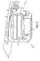
- FIG. 2 is a schematic diagram illustrating a partial side view of a supercharger positioned under the hood of an automobile in accordance with an embodiment of the present invention
- FIG. 3 is a schematic diagram illustrating a cross-sectional view of the supercharger taken generally along lines III-III in FIG. 1 ;
- FIG. 4 is a schematic diagram illustrating a cross-sectional view of the supercharger taken generally along lines IV-IV in FIG. 1 ;
- FIG. 5 is a schematic diagram illustrating an exploded view of a supercharger for an internal combustion engine in accordance with an embodiment of the present invention.
- FIG. 6 is a schematic diagram illustrating a supercharger positioned in the engine bay of an automobile in accordance with an embodiment of the present invention.
- FIGS. 1 , 2 , 3 , 4 , 5 , and 6 illustrate an apparatus 10 for boosting engine performance in accordance with an embodiment of the present invention.
- apparatus 10 is a low profile supercharger 10 .
- supercharger 10 feeds air charge into a V-shaped eight cylinder (V-8) engine 60 .
- V-8 V-shaped eight cylinder
- supercharger 10 is nestled in a valley between engine heads 61 and 62 of engine 60 in accordance with a preferred embodiment of the present invention.
- Supercharger 10 includes a throttle body 12 in the front connected to an air inlet 14 at top of supercharger 10 for taking in fresh air. Throttle body 12 is also connected via an intake air path tube 11 to an air filter 13 (shown in FIG. 6 ). An intake or pre-boost air passage 16 couples air inlet 14 to a compressor 18 located in a compressor chamber 21 . As shown in FIGS. 2 , 3 , and 4 , compressor chamber 21 is at the bottom of supercharger 20 remote from the section of air passage 16 at the top of supercharger 10 . As shown in FIGS.
- intake air passage 16 runs from air inlet 14 , first along the top and then down along one side, e.g., the rear side, of supercharger 10 , to an air outlet integrally coupled to compressor chamber 21 at the bottom of supercharger 10 .
- cross-sectional areas of air inlet 14 and air passage 16 are sufficient large to provide unrestricted airflow for feeding charge into engine 60 .
- the rear side of supercharger 10 is substantially perpendicular to the top of supercharger 10 in accordance with a specific embodiment of the present invention.
- Air inlet 14 preferably has a low height and wide width, i.e., a low aspect ratio.
- air passage 16 preferably has a low aspect ratio so that supercharger 10 can fit under an engine hood 25 (shown in FIG. 2 ) without a hood scoop.
- the cross-sectional areas of air inlet 14 and air passage 16 are preferably about ninety square centimeters (90 cm 2 ) when the cylindrical volume of engine 60 is about four liters.
- the vertical dimension of inlet 14 is about 2.7 centimeters and its horizontal width is about 23.0 centimeters.
- inlet 14 has an aspect ratio of approximately 0.12.
- air inlet 14 and air passage 16 may have other dimensions and aspect ratios, e.g., aspect ratios ranging between 0.1 and 0.5, etc.
- the vertical dimension of air passage 16 further shrinks and its horizontal width increases as air passage 16 runs from air inlet 14 toward the rear of supercharger 10 , thereby achieving a low profile while maintaining the cross-sectional area for the pre-boost airflow.
- air passage 16 bends downward in a bent section 17 .
- air passage 16 bends again in a bent section 19 toward gas compressor 18 .
- the cross-sectional area of air passage 16 increases further around bent sections 17 and 19 to minimize the restriction to the airflow that might be caused by the bending of air passage 16 .
- compressor 18 In compressor chamber 21 at the bottom of supercharger 10 , compressor 18 , which is also referred to as a booster or a blower, compresses the air flowing from intake air passage 16 .
- compressor 18 is a twin-screw type booster that pulls air through a pair of meshing lobes. As the air passes through the meshing lobes in the twin-screw type booster, the air pocket decreases in size and eventually pops as it exits compressor 18 .
- Compressor 18 is mechanically couple to the crankshaft of engine 60 via a belt, a chain, or a gear.
- the mechanical coupling is such that compressor 18 rotates at a speed higher than that of engine 60 , thereby ensuring that compressor 18 generates a positive air pressure.
- the twin lobes push about 2,300 cubic centimeters (cc) of air through compressor 18 per rotation.
- the twin-screw type compressor is preferred because it offers a good balance between thermal efficiency and boost power at low rotation speed.
- compressor 18 is not limited to being a twin-screw type compressor.
- supercharger 10 may include other types of compressor, e.g., a Roots type compressor or a centrifugal type compressor.
- the compressed or boosted air exits compressor 18 in compressor chamber 21 and enters a plenum 22 directly above compressor chamber 21 .
- the boosted air flows through an intercooler 24 in accordance with a preferred embodiment of the present invention.
- Plenum 22 preferably has a large cross-sectional area to minimize the restriction to the airflow and to accommodate a large cross-sectional area intercooler 24 .
- Intercooler 24 having a large cross-sectional area is preferred because of its high heat exchange efficiency.
- a large cross-sectional area intercooler 24 can have a relatively small thickness, e.g., a thickness between approximately 0.5 cm and approximately 3 cm. Thin intercooler 24 minimizes the restriction to the airflow. Consequently, the air pressure drop across intercooler 24 is small.
- intercooler 24 is liquid cooled. However, this is not a limitation on the scope of the present invention. In accordance with an alternative embodiment of the present invention, intercooler 24 is air cooled.
- Engine hood 25 (shown in FIG. 2 ) preferably has one or more air vents to direct cold air to an air cooled intercooler in supercharger 10 .
- FIG. 3 shows engine 60 as a V-8 engine having four intake runners on each side of the engine intake manifold.
- compressor 18 is at the bottom of supercharger 10 and deep in the valley between engine heads 61 and 62
- intercooler 24 is near the top of supercharger 10 above engine heads 61 and 62 . Therefore, intake ports 26 are located above engine heads 61 and 62 .
- This structural arrangement of the different components in supercharger 10 enables intake runners 28 to be long with minimum bends and minimum restriction to the airflow. As shown in FIG.
- each of runners 28 in supercharger 10 has only one obtuse bend from intake port 26 to engine head 61 or 62 in accordance with a preferred embodiment of the present invention.
- Such long and beefy downdraft runners 28 with minimal bends are advantageous for maximizing torque and power. They provide straight and direct shot into the cylinders that maximizes the airflow.
- Long and straight intake manifold runners 28 allows a large amount of air charge to be pumped into engine 60 without having to use as much pressure as in the runners of conventional superchargers. The reduced pressure of the air in intake manifold runners 28 also minimizes the generation of heat in the air charge.
- the outer casing of supercharger 10 is made up of a top piece, element, or unit 32 and a bottom piece, element, or unit 34 ( FIG. 5 ).
- Top piece 32 includes inlet 14 , the top section of air passage 16 , and a top potion or simply a cover of plenum 22 .
- Bottom piece 34 includes the rear section of air passage 16 , a bottom portion of plenum 22 for housing intercooler 24 and compressor chamber 21 for housing compressor 18 , and runners 28 .
- the bottom portion of plenum 22 includes both the floor and the sidewalls. Runners 28 have their intake ports formed in upper sections of the sidewalls of plenum 22 .
- Top piece 32 and bottom piece 34 can be made of cast or forged metals. Top piece 32 and bottom piece 34 can be mechanically coupled to each other by such mechanical fastening devices as screws, bolts and nuts, clips, latches, etc.
- a seal (not shown in FIG. 5 ) is preferably disposed between mating or sealing surfaces 33 and 35 of top piece 32 and bottom piece 34 , respectively.
- Supercharger 10 with a small number of sealing surfaces is beneficial because of its high efficiency and high reliability in maintaining the positive air pressure in supercharger 10 .
- the two piece outer casing structure makes supercharger 10 simple, reliable, and easy to maintain.
- the components, e.g., intercooler 24 and compressor 18 , of supercharger 10 can be easily accessed for maintenance, repair, or replacement by loosening the mechanical fasteners, e.g., bolts that bolt top piece 32 and bottom piece 34 together, and removing top piece 32 .
- Supercharger 10 may include a supercharge bypass (not shown in the figures) in accordance with an embodiment of the present invention.
- the bypass is activated at low engine speed when there is no need for the engine boost.
- the bypass functions to reduce heat buildup in the engine and provide optimal engine performance under difference driving conditions.
- the supercharger has a low profile pre-boost air passage running along the top and rear of the supercharger to a compressor at the bottom of the supercharger.
- the boosted air flows upwards through a large area and thin intercooler into a plenum near the top of the supercharger. From the plenum, the air is fed to the engine intake manifold runners.
- the supercharger is installed in the valley of a V-engine so that it can fit under the engine hood of a stock car without a hood scoop.
- the intercooler above compressor design of the supercharger in accordance with an embodiment of the present invention results in long downdraft intake runners with minimum bends, which is advantageous in feeding large quantities of low boost pressure, e.g., about 30 kilopascal (kPa) or 4.5 pounds per square inch (psi), and low temperature, e.g., about 65 degrees Celsius (° C.) or 150 degrees Fahrenheit (° F.), air charge into the engine.
- the low boost pressure and low temperature place less strain on the engine and also reduce the chance of detonation.
- a supercharger in accordance with a specific embodiment of the present invention installed on a four-liter V-8 engine boosts the engine power to about 400 horsepower or about 300 kilowatts and with about 420 lb-ft or about 570 N-m of torque.
- a supercharger in accordance with a preferred embodiment of the present invention has as few as only one sealing surface. Its outer casing can be made up of as few as only one top piece and one bottom piece. Therefore, the supercharger has a high air sealing efficiency and is simple, reliable, and easy to maintain or repair.
- Present invention provides a low profile, low boost pressure, and low temperature booster for an internal combustion engine.
- the low profile is achieved via the low aspect ratio of air inlet and the pre-boost air passage, as well as the overall arrangement of the different components in the supercharger.
- the low boost pressure and low temperature are achieved by the large cross sectional area pre-boost air passage, large area and thin intercooler, and large and straight post-boost air passage runners.
- the scope of the present invention covers any combination of the above described features and their combinations with other features.
- a supercharger in accordance with an embodiment of the present invention can have more than one sealing surfaces and its outer casing can be made up of more than one top piece and one bottom piece.
- a turbo booster or turbo supercharger is within the scope of the present invention.
- a supercharger in accordance with an embodiment of the present invention can be installed on other types of engines in different applications, e.g., an inline gasoline engine, a diesel engine, a stationary engine, a boat engine, etc.
- those phrases describing the orientation or directions e.g., up, down, above, below, front, rear, top, bottom, are used in the specification for the ease of describing the various embodiments of the present invention with reference to the drawings. These phrases are not intended to impost any limitation on the scope of the present invention.
- the present invention can be practiced with superchargers with different orientations.
Abstract
Description
Claims (21)
Priority Applications (1)
| Application Number | Priority Date | Filing Date | Title |
|---|---|---|---|
| US11/467,128 US7597088B2 (en) | 2005-08-26 | 2006-08-24 | Apparatus and method for boosting engine performance |
Applications Claiming Priority (2)
| Application Number | Priority Date | Filing Date | Title |
|---|---|---|---|
| US71161005P | 2005-08-26 | 2005-08-26 | |
| US11/467,128 US7597088B2 (en) | 2005-08-26 | 2006-08-24 | Apparatus and method for boosting engine performance |
Publications (2)
| Publication Number | Publication Date |
|---|---|
| US20070175456A1 US20070175456A1 (en) | 2007-08-02 |
| US7597088B2 true US7597088B2 (en) | 2009-10-06 |
Family
ID=37772469
Family Applications (1)
| Application Number | Title | Priority Date | Filing Date |
|---|---|---|---|
| US11/467,128 Expired - Fee Related US7597088B2 (en) | 2005-08-26 | 2006-08-24 | Apparatus and method for boosting engine performance |
Country Status (2)
| Country | Link |
|---|---|
| US (1) | US7597088B2 (en) |
| WO (1) | WO2007025204A2 (en) |
Cited By (6)
| Publication number | Priority date | Publication date | Assignee | Title |
|---|---|---|---|---|
| US20090071450A1 (en) * | 2005-04-19 | 2009-03-19 | Audi Ag | Charger module for an internal combustion engine |
| US20090260906A1 (en) * | 2008-04-17 | 2009-10-22 | Derk Hartland | Automotive Vehicle Engine Apparatus |
| US20130282259A1 (en) * | 2011-01-14 | 2013-10-24 | Toyota Jidosha Kabushiki Kaisha | Control apparatus for internal combustion engine with supercharger |
| US20140144132A1 (en) * | 2011-11-30 | 2014-05-29 | Cummins Intellectual Property, Inc. | Charge air cooler assembly |
| USD737332S1 (en) | 2014-04-17 | 2015-08-25 | Callaway Cars, Inc. | Induction housing |
| US20150354511A1 (en) * | 2013-01-16 | 2015-12-10 | Toyota Jidosha Kabushiki Kaisha | Internal combustion engine with supercharger |
Families Citing this family (17)
| Publication number | Priority date | Publication date | Assignee | Title |
|---|---|---|---|---|
| GB0520415D0 (en) * | 2005-10-07 | 2005-11-16 | Ford Global Tech Llc | A v type internal combustion engine |
| CN101512122B (en) * | 2006-09-13 | 2012-09-05 | 博格华纳公司 | Integration of an exhaust air cooler into a turbocharger |
| US8209983B2 (en) * | 2008-06-25 | 2012-07-03 | Ford Global Technologies, Llc | Turbocharger system for internal combustion engine with reduced footprint turbocharger mounting pedestal |
| US8245511B2 (en) * | 2008-06-25 | 2012-08-21 | Ford Global Technologies, Llc | Cylinder block mounted pedestal and turbocharger system for internal combustion engine |
| US8215113B2 (en) | 2008-06-25 | 2012-07-10 | Ford Global Technologies, Llc | Pedestal mounted turbocharger system for internal combustion engine |
| US8234867B2 (en) * | 2008-06-25 | 2012-08-07 | Ford Global Technologies, Llc | Turbocharger system for internal combustion engine with internal isolated turbocharger oil drainback passage |
| WO2010062774A2 (en) * | 2008-11-03 | 2010-06-03 | Edlebrock Corporation | Supercharger system for motorized vehicles and related transportation |
| US10202892B2 (en) * | 2008-11-03 | 2019-02-12 | Edelbrock Corporation | Supercharger system for motorized vehicles and related transportation |
| SE533056C2 (en) * | 2008-11-28 | 2010-06-15 | Scania Cv Ab | Charge air cooler for cooling air which is led to a supercharged internal combustion engine |
| US20100258096A1 (en) * | 2009-04-09 | 2010-10-14 | SMS Supercars, Inc. | Intercooler cartridge assembly design for improving internal combustion engine performance |
| US8539936B2 (en) * | 2009-10-20 | 2013-09-24 | James E. Bell | Supercharger rotor shaft seal pressure equalization |
| FR2968719B1 (en) * | 2010-12-10 | 2012-12-21 | Valeo Systemes Thermiques | DEVICE FOR PIPING A SUPPLY GAS FLOW OF AN INTERNAL COMBUSTION ENGINE |
| US20140032080A1 (en) * | 2012-07-27 | 2014-01-30 | Caterpillar Inc. | Reactivity Controlled Compression Ignition Engine with Intake Cooling Operating on a Miller Cycle and Method |
| USD814523S1 (en) * | 2017-02-15 | 2018-04-03 | Brunswick Corporation | Engine plenum chamber |
| USD978913S1 (en) | 2020-08-21 | 2023-02-21 | Holley Performance Products, Inc. | Manifold |
| USD967860S1 (en) | 2020-10-20 | 2022-10-25 | Holley Performance Products, Inc. | Manifold |
| USD967859S1 (en) * | 2020-10-20 | 2022-10-25 | Holley Performance Products, Inc. | Manifold |
Citations (39)
| Publication number | Priority date | Publication date | Assignee | Title |
|---|---|---|---|---|
| US1883464A (en) | 1932-01-08 | 1932-10-18 | Briggs Mfg Co | Ventilator construction |
| US2571256A (en) | 1946-09-06 | 1951-10-16 | United Aircraft Corp | Refrigerant cooled intercooler |
| US2963006A (en) | 1957-07-12 | 1960-12-06 | Harnischfeger Corp | Two cycle super charged internal combustion engine |
| US3641746A (en) | 1969-09-08 | 1972-02-15 | Chrysler Corp | Carburetor air delivery system |
| US4058096A (en) | 1975-02-18 | 1977-11-15 | Stephen Edward Brown | Apparatus and method for increasing the horsepower of an internal combustion engine |
| US4723526A (en) | 1985-03-19 | 1988-02-09 | Yamaha Hatsudoki Kabushiki Kaisha | Drive arrangement for supercharger |
| US4831981A (en) | 1987-07-27 | 1989-05-23 | Nissan Motor Co., Ltd. | Sealing structure around intercooler |
| US4878460A (en) | 1987-10-30 | 1989-11-07 | Mazda Motor Corporation | Intake system for V-type internal combustion engine |
| US4896734A (en) | 1985-03-27 | 1990-01-30 | Yamaha Hatsudoki Kabushiki Kaisha | Supercharged motor vehicle |
| US4911135A (en) | 1988-01-18 | 1990-03-27 | Nissan Motor Co., Ltd. | Intake air cooling arrangement for turbocharged internal combustion engine |
| US4977865A (en) | 1988-10-19 | 1990-12-18 | Mazda Motor Corporation | Intake system for V-type engine |
| US5012771A (en) | 1989-02-28 | 1991-05-07 | Mazda Motor Corporation | Intake system for multi-cylinder engine |
| US5058558A (en) | 1988-10-07 | 1991-10-22 | Mazda Motor Corporation | Air feeding system for a vehicle engine equipped with a supercharger |
| US5085199A (en) | 1989-01-31 | 1992-02-04 | Mazda Motor Corporation | V-type engine equipped with a supercharging device |
| USD328063S (en) | 1990-10-19 | 1992-07-21 | Franklin Yunes | Cold air scoop for automotive vehicle |
| US5392751A (en) | 1992-09-24 | 1995-02-28 | Mazda Motor Corporation | V-type engine with supercharger mounting |
| US5448982A (en) | 1991-09-30 | 1995-09-12 | Mazda Motor Corporation | Intake system for an internal combustion engine with a supercharger |
| US5911211A (en) | 1995-12-28 | 1999-06-15 | Yamaha Hatsudoki Kabushiki Kaisha | Supercharged engine |
| US6006540A (en) | 1998-08-03 | 1999-12-28 | Ford Global Technologies, Inc. | Charge air management system for automotive engine |
| US6021764A (en) | 1997-01-31 | 2000-02-08 | Suzuki Motor Corporation | Air intake structure for an engine with a supercharger |
| US6029637A (en) | 1998-12-16 | 2000-02-29 | General Motors Corporation | Induction assembly for supercharged internal combustion engine |
| US6079394A (en) | 1997-12-20 | 2000-06-27 | Daimlerchrysler Ag | Mechanical supercharger for an internal combustion engine and a method of making same |
| US6098586A (en) | 1997-08-27 | 2000-08-08 | Siemens Canada Limited | Integrated intake manifold and air cleaner system |
| USD429672S (en) | 1998-10-30 | 2000-08-22 | Stuart Miyagishma | Air scoop assembly |
| US6227179B1 (en) | 1998-09-05 | 2001-05-08 | Daimlerchrysler Ag | V-type internal combustion engine with a mechanically driven supercharger |
| US6405692B1 (en) | 2001-03-26 | 2002-06-18 | Brunswick Corporation | Outboard motor with a screw compressor supercharger |
| US6463901B1 (en) | 2000-03-28 | 2002-10-15 | Brendan R. Cuddihee, Sr. | Method and device for improving air intake for fuel injection engines |
| USD491503S1 (en) | 2003-03-11 | 2004-06-15 | Joseph A. Zyskowski | Hood air scoop feature |
| US6837195B2 (en) | 2001-09-26 | 2005-01-04 | Ogura Clutch Co., Ltd. | V-engine supercharging device |
| US20050150483A1 (en) | 2004-01-08 | 2005-07-14 | Sorensen John C. | Apparatus for increasing induction air flow rate to a turbocharger |
| US6923166B2 (en) | 2003-09-30 | 2005-08-02 | Trilogy Motorsports, Llc | Supercharging assembly for an internal combustion engine of a motor vehicle |
| US6941926B2 (en) * | 2003-08-25 | 2005-09-13 | Jeffrey A. Fagala | Air intake system for an internal combustion engine |
| US7011079B2 (en) * | 2003-12-24 | 2006-03-14 | Hyundai Motor Company | Intake apparatus for engine of vehicle |
| US20060157036A1 (en) | 2005-01-18 | 2006-07-20 | Ekm Engineering, Inc. | Positive displacement supercharging apparatus for use in an in-line internal combustion engine and its method of formation |
| USD528482S1 (en) | 2005-05-04 | 2006-09-19 | Advanced Composite Specialties-Us, Inc. | Vehicle hood scoop attachment |
| WO2006099668A1 (en) | 2005-03-24 | 2006-09-28 | Richwood Creek Pty Ltd | An apparatus for a vehicle |
| US7137384B1 (en) | 2005-01-13 | 2006-11-21 | High Performance Systems, Llc | Modular supercharger system |
| US20070107704A1 (en) | 2005-10-07 | 2007-05-17 | Andy Billings | Supercharger and Air Inlet Assembly for a V Type Internal Combustion Engine |
| US20080083575A1 (en) | 2006-04-07 | 2008-04-10 | Messerschmitt Design Ltd. | External air scoop for internal combustion engine air intake of an automobile |
-
2006
- 2006-08-24 US US11/467,128 patent/US7597088B2/en not_active Expired - Fee Related
- 2006-08-24 WO PCT/US2006/033350 patent/WO2007025204A2/en active Application Filing
Patent Citations (42)
| Publication number | Priority date | Publication date | Assignee | Title |
|---|---|---|---|---|
| US1883464A (en) | 1932-01-08 | 1932-10-18 | Briggs Mfg Co | Ventilator construction |
| US2571256A (en) | 1946-09-06 | 1951-10-16 | United Aircraft Corp | Refrigerant cooled intercooler |
| US2963006A (en) | 1957-07-12 | 1960-12-06 | Harnischfeger Corp | Two cycle super charged internal combustion engine |
| US3641746A (en) | 1969-09-08 | 1972-02-15 | Chrysler Corp | Carburetor air delivery system |
| US4058096A (en) | 1975-02-18 | 1977-11-15 | Stephen Edward Brown | Apparatus and method for increasing the horsepower of an internal combustion engine |
| US4723526A (en) | 1985-03-19 | 1988-02-09 | Yamaha Hatsudoki Kabushiki Kaisha | Drive arrangement for supercharger |
| US4896734A (en) | 1985-03-27 | 1990-01-30 | Yamaha Hatsudoki Kabushiki Kaisha | Supercharged motor vehicle |
| US4831981A (en) | 1987-07-27 | 1989-05-23 | Nissan Motor Co., Ltd. | Sealing structure around intercooler |
| US4878460A (en) | 1987-10-30 | 1989-11-07 | Mazda Motor Corporation | Intake system for V-type internal combustion engine |
| US4911135A (en) | 1988-01-18 | 1990-03-27 | Nissan Motor Co., Ltd. | Intake air cooling arrangement for turbocharged internal combustion engine |
| US5058558A (en) | 1988-10-07 | 1991-10-22 | Mazda Motor Corporation | Air feeding system for a vehicle engine equipped with a supercharger |
| US4977865A (en) | 1988-10-19 | 1990-12-18 | Mazda Motor Corporation | Intake system for V-type engine |
| US5085199A (en) | 1989-01-31 | 1992-02-04 | Mazda Motor Corporation | V-type engine equipped with a supercharging device |
| US5012771A (en) | 1989-02-28 | 1991-05-07 | Mazda Motor Corporation | Intake system for multi-cylinder engine |
| USD328063S (en) | 1990-10-19 | 1992-07-21 | Franklin Yunes | Cold air scoop for automotive vehicle |
| US5448982A (en) | 1991-09-30 | 1995-09-12 | Mazda Motor Corporation | Intake system for an internal combustion engine with a supercharger |
| US5392751A (en) | 1992-09-24 | 1995-02-28 | Mazda Motor Corporation | V-type engine with supercharger mounting |
| US5911211A (en) | 1995-12-28 | 1999-06-15 | Yamaha Hatsudoki Kabushiki Kaisha | Supercharged engine |
| US6021764A (en) | 1997-01-31 | 2000-02-08 | Suzuki Motor Corporation | Air intake structure for an engine with a supercharger |
| US6098586A (en) | 1997-08-27 | 2000-08-08 | Siemens Canada Limited | Integrated intake manifold and air cleaner system |
| US6079394A (en) | 1997-12-20 | 2000-06-27 | Daimlerchrysler Ag | Mechanical supercharger for an internal combustion engine and a method of making same |
| US6006540A (en) | 1998-08-03 | 1999-12-28 | Ford Global Technologies, Inc. | Charge air management system for automotive engine |
| US6227179B1 (en) | 1998-09-05 | 2001-05-08 | Daimlerchrysler Ag | V-type internal combustion engine with a mechanically driven supercharger |
| USD429672S (en) | 1998-10-30 | 2000-08-22 | Stuart Miyagishma | Air scoop assembly |
| US6029637A (en) | 1998-12-16 | 2000-02-29 | General Motors Corporation | Induction assembly for supercharged internal combustion engine |
| US6463901B1 (en) | 2000-03-28 | 2002-10-15 | Brendan R. Cuddihee, Sr. | Method and device for improving air intake for fuel injection engines |
| US6405692B1 (en) | 2001-03-26 | 2002-06-18 | Brunswick Corporation | Outboard motor with a screw compressor supercharger |
| US6837195B2 (en) | 2001-09-26 | 2005-01-04 | Ogura Clutch Co., Ltd. | V-engine supercharging device |
| USD491503S1 (en) | 2003-03-11 | 2004-06-15 | Joseph A. Zyskowski | Hood air scoop feature |
| US6941926B2 (en) * | 2003-08-25 | 2005-09-13 | Jeffrey A. Fagala | Air intake system for an internal combustion engine |
| US6923166B2 (en) | 2003-09-30 | 2005-08-02 | Trilogy Motorsports, Llc | Supercharging assembly for an internal combustion engine of a motor vehicle |
| US7011079B2 (en) * | 2003-12-24 | 2006-03-14 | Hyundai Motor Company | Intake apparatus for engine of vehicle |
| US20050150483A1 (en) | 2004-01-08 | 2005-07-14 | Sorensen John C. | Apparatus for increasing induction air flow rate to a turbocharger |
| US7137384B1 (en) | 2005-01-13 | 2006-11-21 | High Performance Systems, Llc | Modular supercharger system |
| US7201157B1 (en) | 2005-01-13 | 2007-04-10 | High Performance Systems, Llc | Modular supercharger with a cooling system |
| US20060157036A1 (en) | 2005-01-18 | 2006-07-20 | Ekm Engineering, Inc. | Positive displacement supercharging apparatus for use in an in-line internal combustion engine and its method of formation |
| AU2006202679C1 (en) | 2005-03-24 | 2006-10-12 | Genesis Group International (Usa) Inc | An apparatus for a vehicle |
| AU2006100924A5 (en) | 2005-03-24 | 2006-11-16 | Genesis Group International (Usa) Inc | An apparatus for a vehicle |
| WO2006099668A1 (en) | 2005-03-24 | 2006-09-28 | Richwood Creek Pty Ltd | An apparatus for a vehicle |
| USD528482S1 (en) | 2005-05-04 | 2006-09-19 | Advanced Composite Specialties-Us, Inc. | Vehicle hood scoop attachment |
| US20070107704A1 (en) | 2005-10-07 | 2007-05-17 | Andy Billings | Supercharger and Air Inlet Assembly for a V Type Internal Combustion Engine |
| US20080083575A1 (en) | 2006-04-07 | 2008-04-10 | Messerschmitt Design Ltd. | External air scoop for internal combustion engine air intake of an automobile |
Cited By (11)
| Publication number | Priority date | Publication date | Assignee | Title |
|---|---|---|---|---|
| US20090071450A1 (en) * | 2005-04-19 | 2009-03-19 | Audi Ag | Charger module for an internal combustion engine |
| US8418679B2 (en) * | 2005-04-19 | 2013-04-16 | Audi Ag | Charger module for an internal combustion engine |
| US20090260906A1 (en) * | 2008-04-17 | 2009-10-22 | Derk Hartland | Automotive Vehicle Engine Apparatus |
| US8181728B2 (en) * | 2008-04-17 | 2012-05-22 | Mj Acquisitions, Inc. | Automotive vehicle engine apparatus |
| US20130282259A1 (en) * | 2011-01-14 | 2013-10-24 | Toyota Jidosha Kabushiki Kaisha | Control apparatus for internal combustion engine with supercharger |
| US8666636B2 (en) * | 2011-01-14 | 2014-03-04 | Toyota Jidosha Kabushiki Kaisha | Control apparatus for internal combustion engine with supercharger |
| US20140144132A1 (en) * | 2011-11-30 | 2014-05-29 | Cummins Intellectual Property, Inc. | Charge air cooler assembly |
| US9562467B2 (en) * | 2011-11-30 | 2017-02-07 | Cummins Intellectual Property, Inc. | Charge air cooler assembly |
| US20150354511A1 (en) * | 2013-01-16 | 2015-12-10 | Toyota Jidosha Kabushiki Kaisha | Internal combustion engine with supercharger |
| US9915233B2 (en) * | 2013-01-16 | 2018-03-13 | Toyota Jidosha Kabushiki Kaisha | Internal combustion engine with supercharger |
| USD737332S1 (en) | 2014-04-17 | 2015-08-25 | Callaway Cars, Inc. | Induction housing |
Also Published As
| Publication number | Publication date |
|---|---|
| US20070175456A1 (en) | 2007-08-02 |
| WO2007025204A2 (en) | 2007-03-01 |
| WO2007025204A3 (en) | 2007-09-07 |
Similar Documents
| Publication | Publication Date | Title |
|---|---|---|
| US7597088B2 (en) | Apparatus and method for boosting engine performance | |
| EP2342461B1 (en) | Supercharger system for motorized vehicles | |
| US8220264B2 (en) | Integrated inboard exhaust manifolds for V-type engines | |
| US20060157036A1 (en) | Positive displacement supercharging apparatus for use in an in-line internal combustion engine and its method of formation | |
| US5911211A (en) | Supercharged engine | |
| JP4889728B2 (en) | Supercharger module for internal combustion engines | |
| US20060168958A1 (en) | Supercharged internal combustion engine | |
| US20100258096A1 (en) | Intercooler cartridge assembly design for improving internal combustion engine performance | |
| US4932368A (en) | Suction arrangement for internal combustion engine | |
| US6408832B1 (en) | Outboard motor with a charge air cooler | |
| US4702079A (en) | Air-cooled type intercooler for a supercharged internal combustion engine | |
| CA2578729A1 (en) | Air intake structure for small watercraft | |
| US5058558A (en) | Air feeding system for a vehicle engine equipped with a supercharger | |
| US4537173A (en) | Free-running rotary induction system | |
| US6726457B2 (en) | Compressor with supercharged inlet | |
| GB2045866A (en) | A supercharged I.C. engine with an auxiliary compressor | |
| JP6399041B2 (en) | Turbocharged engine | |
| US10202892B2 (en) | Supercharger system for motorized vehicles and related transportation | |
| US20040173343A1 (en) | Heat exchange assembly | |
| JPH08312475A (en) | Suction system for engine with mechanism super charger | |
| US4741162A (en) | Engine with turbo-charger for an outboard motor | |
| US7008175B2 (en) | Radiator cooling fan replacement to increase engine efficiency | |
| JPH0216330A (en) | Motorcycle provided with engine having turbocharger | |
| US20230349346A1 (en) | Air intake device | |
| JPS60248438A (en) | Motor-cycle having turbocharger |
Legal Events
| Date | Code | Title | Description |
|---|---|---|---|
| AS | Assignment |
Owner name: MJ ACQUISITIONS, INC., MICHIGAN Free format text: ASSIGNMENT OF ASSIGNORS INTEREST;ASSIGNOR:SALEEN INCORPORATED;REEL/FRAME:024710/0701 Effective date: 20090428 |
|
| AS | Assignment |
Owner name: SALEEN INCORPORATED, A DELAWARE CORPORATION, MICHI Free format text: MERGER;ASSIGNOR:SALEEN INCORPORATED, A CALIFORNIA CORPORATION;REEL/FRAME:023109/0946 Effective date: 20030922 |
|
| AS | Assignment |
Owner name: MJ ACQUISITIONS, INC.,MICHIGAN Free format text: ASSET PURCHASE AGREEMENT;ASSIGNOR:SALEEN INCORPORATED;REEL/FRAME:024492/0374 Effective date: 20090130 Owner name: MJ ACQUISITIONS, INC., MICHIGAN Free format text: ASSET PURCHASE AGREEMENT;ASSIGNOR:SALEEN INCORPORATED;REEL/FRAME:024492/0374 Effective date: 20090130 |
|
| REMI | Maintenance fee reminder mailed | ||
| LAPS | Lapse for failure to pay maintenance fees | ||
| STCH | Information on status: patent discontinuation |
Free format text: PATENT EXPIRED DUE TO NONPAYMENT OF MAINTENANCE FEES UNDER 37 CFR 1.362 |
|
| FP | Expired due to failure to pay maintenance fee |
Effective date: 20131006 |