US7594352B2 - Device mount with stabilizing function - Google Patents
Device mount with stabilizing function Download PDFInfo
- Publication number
- US7594352B2 US7594352B2 US11/550,127 US55012706A US7594352B2 US 7594352 B2 US7594352 B2 US 7594352B2 US 55012706 A US55012706 A US 55012706A US 7594352 B2 US7594352 B2 US 7594352B2
- Authority
- US
- United States
- Prior art keywords
- stabilizing
- device mount
- stabilizing tube
- mounting rail
- mount
- Prior art date
- Legal status (The legal status is an assumption and is not a legal conclusion. Google has not performed a legal analysis and makes no representation as to the accuracy of the status listed.)
- Expired - Fee Related, expires
Links
Images


Classifications
-
- G—PHYSICS
- G03—PHOTOGRAPHY; CINEMATOGRAPHY; ANALOGOUS TECHNIQUES USING WAVES OTHER THAN OPTICAL WAVES; ELECTROGRAPHY; HOLOGRAPHY
- G03B—APPARATUS OR ARRANGEMENTS FOR TAKING PHOTOGRAPHS OR FOR PROJECTING OR VIEWING THEM; APPARATUS OR ARRANGEMENTS EMPLOYING ANALOGOUS TECHNIQUES USING WAVES OTHER THAN OPTICAL WAVES; ACCESSORIES THEREFOR
- G03B29/00—Combinations of cameras, projectors or photographic printing apparatus with non-photographic non-optical apparatus, e.g. clocks or weapons; Cameras having the shape of other objects
-
- F—MECHANICAL ENGINEERING; LIGHTING; HEATING; WEAPONS; BLASTING
- F16—ENGINEERING ELEMENTS AND UNITS; GENERAL MEASURES FOR PRODUCING AND MAINTAINING EFFECTIVE FUNCTIONING OF MACHINES OR INSTALLATIONS; THERMAL INSULATION IN GENERAL
- F16M—FRAMES, CASINGS OR BEDS OF ENGINES, MACHINES OR APPARATUS, NOT SPECIFIC TO ENGINES, MACHINES OR APPARATUS PROVIDED FOR ELSEWHERE; STANDS; SUPPORTS
- F16M13/00—Other supports for positioning apparatus or articles; Means for steadying hand-held apparatus or articles
-
- F—MECHANICAL ENGINEERING; LIGHTING; HEATING; WEAPONS; BLASTING
- F41—WEAPONS
- F41G—WEAPON SIGHTS; AIMING
- F41G11/00—Details of sighting or aiming apparatus; Accessories
- F41G11/001—Means for mounting tubular or beam shaped sighting or aiming devices on firearms
- F41G11/002—Mountings with recoil absorbing means
-
- G—PHYSICS
- G03—PHOTOGRAPHY; CINEMATOGRAPHY; ANALOGOUS TECHNIQUES USING WAVES OTHER THAN OPTICAL WAVES; ELECTROGRAPHY; HOLOGRAPHY
- G03B—APPARATUS OR ARRANGEMENTS FOR TAKING PHOTOGRAPHS OR FOR PROJECTING OR VIEWING THEM; APPARATUS OR ARRANGEMENTS EMPLOYING ANALOGOUS TECHNIQUES USING WAVES OTHER THAN OPTICAL WAVES; ACCESSORIES THEREFOR
- G03B17/00—Details of cameras or camera bodies; Accessories therefor
- G03B17/56—Accessories
- G03B17/561—Support related camera accessories
Definitions
- a device mount in one embodiment, includes a device bracket, a stabilizing tube and at least one stabilizing member.
- the device bracket has a support plate and a side plate that extends generally at a right angle from the support plate.
- the stabilizing tube is movably coupled to the side plate.
- the at least one stabilizing member is received in the stabilizing tube.
- the at least one stabilizing member is configured to stabilize motion of the device bracket.
- another device mount in another embodiment, is provided.
- This device mount includes a device bracket, a stabilizing container, at least one stabilizer and a first mounting rail.
- the device is used to hold a device.
- the stabilizing container is coupled to the device bracket.
- the at least one stabilizer is received in the stabilizing container.
- the stabilizer is configured to stabilize movement of the device bracket.
- the first mounting rail is coupled to the stabilizing container.
- the mounting rail is selectively coupled to a scope ring to connect the device mount to a weapon.
- a device mount in yet another embodiment, includes a device bracket, a stabilizing tube, a first and second spring and a first and second cap.
- the device bracket includes a support plate, a side plate and a bias portion.
- the support plate is configured to hold a device thereto.
- the side plate has a first end that extends from an end of the support plate at a given angle.
- the bias portion of the device bracket extends from a second end of the side plate.
- the stabilizing tube has a receiving aperture configured to slidably receive the bias portion of the device bracket.
- the first and second springs are received in the stabilizing tube in such a manner that the bias portion of the device bracket is positioned between the first and second springs.
- the first cap is used to retain the first spring in the stabilizing tube and the second cap is used to retain the second spring in the stabilizing tube.
- a method of using a device mount for a weapon comprises coupling a first mounting rail attached to a stabilizing container to a weapon, the stabilizer containing one or more stabilizers and coupling a first device to a device bracket that is movably coupled to the stabilizing container.
- the functional integrity of the device is maintained by the one or more stabilizers in the stabilizing container during a discharge of the weapon.
- FIG. 1 is a cut away back view of a device mount of one embodiment of the present invention
- FIG. 2 is a side view of the device mount of FIG. 1 ;
- FIG. 3 is a side view of a device bracket of one embodiment of the present invention.
- FIG. 4 is a top view of the device bracket of FIG. 3 ;
- FIG. 5 is a top view of a stabilizing tube of one embodiment of the present invention.
- FIG. 6 is an end view of the stabilizing tube of FIG. 5 ;
- FIG. 7 is a side view of the stabilizing tube of FIG. 5 ;
- FIG. 8 is a side view of a spring cap of one embodiment of the present invention.
- FIG. 9 is a end view of the spring cap of FIG. 8 ;
- FIG. 10 is a side perspective view of another embodiment of a device mount of the present invention.
- FIG. 11 is a side view of a laser designator being mounted to a second mounting rail of a device mount of one embodiment of the present invention.
- FIG. 12 is a side view of a flashlight being mounted to a second mounting rail of a device mount of one embodiment of the present invention.
- FIG. 13 is a side view of a rangefinder being mounted to a second mounting rail of a device mount of one embodiment of the present invention
- FIG. 14 is a side view of a lipstick camera being mounted to a second mounting rail of a device mount of one embodiment of the present invention.
- FIG. 15 is a side perspective view of yet another embodiment of a device mount of the present invention.
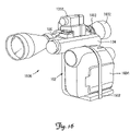
- FIG. 16 is a side perspective view of a device mount of one embodiment of the present having two device mounted thereto.
- Embodiments of the present invention provide a device mount with stabilization features that help devices coupled to the device mount function properly.
- a stabilizing member such as a pair of springs is used to dampen the effects of a sudden movement of a hunting weapon. Such movement may arise because of recoil produced in response to the firing of a rifle or shotgun or the movement in response to the release of an arrow from a bow or crossbow.
- Embodiments of the present invention maintain the functional integrity of devices mounted to the device mount during such movements.
- FIG. 1 illustrates a cut away back view of a device mount 100 of one embodiment of the present invention.
- the device mount 100 includes a stabilizing container 104 and a device bracket 102 .
- the stabilizing container 104 is a stabilizing tube 104 in the embodiment of FIG. 1 . In other embodiments other shapes are used for the stabilizing container 104 .
- a pair of stabilizing members 108 A and 108 B are received in the stabilizing tube 104 .
- the stabilizing members 108 A and 108 B are a pair of springs 108 A and 108 B. In other embodiments, other types of stabilizing members are used. As illustrated in FIG.
- spring 108 A is positioned between cap 110 A and a first engaging surface 111 of a bias portion 112 of the device bracket 102 .
- Spring 108 B is positioned between cap 110 B and a second engaging surface 113 of the bias portion 112 of the device bracket 102 .
- a holding rod 130 is also included in this embodiment.
- the holding rod 130 holds the springs 108 A and 108 B in place.
- a mounting rail 106 selectively engages a scope ring (not shown) which attaches the mount to a weapon such as a rifle, shotgun, bow, crossbow and the like.
- the mounting rail is commercially available rail, such as a weaver mounting rail known in the industry.
- the device bracket 102 includes a support plate 202 that extends from the side plate 204 .
- the support plate 202 extends generally at a right angle from the side plate 204 .
- the support plate 202 is designed to engage a device such as a video camera, rangefinder, game caller and the like.
- FIG. 3 a side view of a device bracket 102 of one embodiment of the present invention is illustrated.
- the device bracket 102 includes the support plate 202 , the side plate 204 and the bias portion 112 .
- the bias portion 112 is received in the stabilizing tube 104 as illustrated in FIG. 1 .
- the bias portion 112 includes a rod aperture 302 .
- the holding rod 130 is received in the rod aperture 302 .
- a brass sleeve 303 lines the rod aperture 302 to reduce friction between the holding rod 103 and the rod aperture 302 .
- the friction reducing sleeve 303 allows the holding rod 130 to slide through the rod aperture 302 in a relatively smooth manner.
- FIG. 4 illustrates a top view of the device bracket 102 .
- the bias portion 112 includes a first and second engaging surfaces 111 and 113 respectfully.
- the engaging surfaces 111 and 113 are designed to engage an end of a respective spring 108 A and 108 B as illustrated in FIG. 1 .
- FIG. 4 also illustrates a plurality of attaching apertures 402 that extend through the support plate 202 .
- the attaching apertures 402 are used to attach a device to the device mount 100 .
- FIG. 5 is a top view of a stabilizing tube 104 of one embodiment of the present invention.
- a mounting rail 106 is attached to the stabilizing tube 104 .
- the mounting rail 106 is used to connect the device mount 100 to a weapon via scope ring.
- a pair of engaging apertures 702 A and 702 B are also illustrated in this view.
- the engaging apertures 702 A and 702 B are used to secure a respective cap 110 A and 110 B in place as illustrated in FIG. 1 .
- a holding member 120 A or 120 B is passed through the respective engaging aperture 702 A or 702 B to hold the respective spring cap 110 A and 110 B in place.
- the engaging apertures 702 A and 702 B are internally threaded and the holding members 120 A and 102 B are externally threaded set screws.
- the external threads on the set screws in this embodiment are designed to engage the internal threads of the engaging apertures 602 A and 702 B.
- FIG. 6 An end view of the stabilizing tube 104 is illustrated in FIG. 6 .
- the stabilizing tube 104 has the mounting rail 106 .
- a receiving aperture 602 is also illustrated in FIG. 6 .
- the receiving aperture 602 is designed to receive the bias portion 112 of the device bracket 102 as illustrated in FIG. 1 .
- FIG. 7 is a side view of the stabilizing tube 104 illustrating the rail mount as well as the engaging apertures 702 A and 702 B.
- Cap 110 is either cap 110 A or 110 B of FIG. 1 .
- the cap 110 includes an engaging end that is designed to engage an end of a stabilizing member as illustrated in relating to 110 A and 110 B of FIG. 1 .
- the cap 110 further includes an engaging recess 806 .
- the engaging recess 806 is designed to receive a respective holding member 120 A and 120 B to lock the cap 110 in place as illustrated in FIG. 1 .
- the cap 110 further has an end portion 804 that is illustrated in FIG. 9 .
- FIG. 10 illustrates another embodiment of a device mount 1000 with a stabilizing feature of the present invention.
- This embodiment includes two mounting rails 106 and 1002 .
- Mounting rail 106 is used as discussed above to couple the mounting rail to a hunting weapon.
- the second mounting rail 1002 is used to attach a second device to the mount.
- two devices can be mounted to the weapon, one on the support plate 202 and one on the second mounting rail 1002 .
- FIG. 11 the device is a laser designator 1102 .
- a laser designator 1102 projects a laser beam to a target.
- the laser designator 1102 includes a receiving mounting track 1104 that is designed to selectively engage the second mounting rail 1002 .
- a device is a flashlight 1202 .
- the flash light is attached to the mount 102 via device connector 1204 that includes a receiving mounting track 1206 that selectively engages the second mounting rail 1002 .
- the device is a rangefinder 1302 that includes a receiving mounting track 1304 that selectively engages the second mounting rail 1002 of the device mount 102 . This is illustrated in FIG. 13 .
- a lipstick camera 1402 is coupled to the second mounting rail 1002 via a pair of scope mount rings 1406 and 1404 .
- FIG. 15 another device mount 1500 of another embodiment is illustrated.
- two mounting rails 106 and 1002 are provided on the stabilizer container 104 .
- a stabilizing strap 1502 is used.
- the stabilizing strap 1502 is designed to stabilize a device on the support plate 202 of the device mount device 1500 .
- the stabilizing strap 1502 is made from an elastic material.
- a first end 1506 of the stabilizing strap 1502 is coupled to the side plate 204 . In other embodiments, the first end 1506 of the stabilizing strap 1502 is coupled to support plate 202 (not shown).
- a second end of the stabilizing strap 1502 includes a hook 1504 that is designed to be selectively positioned in one of the mounting apertures 402 in the support plate 202 of the mount device 1500 to stabilize the device.
- FIG. 16 illustrates stabilizing strap 1502 stabilizing a device 1604 to the device mount 1500 .
- FIG. 16 also illustrates, two devices 1604 and 1302 mounted to device mount 1500 as well as the device mount 1500 being coupled to a scope 1602 of a weapon.
- the device mount 1500 is coupled to scope 1602 via the first mounting rail 106 and one or scope rings.
- the second device 1302 a laser designator 1302 , is coupled to the second mounting rail 1002 .
- the device mount 1500 can be mounted on the right or left side of the weapon or scope 1602 as illustrated.
Landscapes
- Engineering & Computer Science (AREA)
- General Engineering & Computer Science (AREA)
- Physics & Mathematics (AREA)
- General Physics & Mathematics (AREA)
- Mechanical Engineering (AREA)
- Aiming, Guidance, Guns With A Light Source, Armor, Camouflage, And Targets (AREA)
Abstract
A device mount for a weapon with a stabilizing function is provided. In one embodiment, the device mount includes a device bracket, a stabilizing tube and at least one stabilizing member. The device bracket has a support plate and a side plate that extends generally at a right angle from the support plate. The stabilizing tube is movably coupled to the side plate. The at least one stabilizing member is received in the stabilizing tube. Moreover, the at least one stabilizing member is configured to stabilize motion of the device bracket.
Description
For game hunters the ability to record the hunt in an efficient manner is desired. Moreover, the ability to attach other devices such as rangefinders and other electronic device to the weapon in a manner that does not impede the hunt is also desired. For the reasons stated above and for other reasons stated below which will become apparent to those skilled in the art upon reading and understanding the present specification, there is a need in the art for a mount that can attach a device such an electronic device to a weapon in an effective and un-intrusive manner and provide stabilizing functions to aid the function of the devices.
The above-mentioned problems of current systems are addressed by embodiments of the present invention and will be understood by reading and studying the following specification. The following summaries are provided as way of examples and not by way of limitation. Moreover, the summaries may include more or less elements than are in the claims and are merely provided to give the reader a basic understanding of some of the elements of the present invention.
In one embodiment, a device mount is provided. The device mount includes a device bracket, a stabilizing tube and at least one stabilizing member. The device bracket has a support plate and a side plate that extends generally at a right angle from the support plate. The stabilizing tube is movably coupled to the side plate. The at least one stabilizing member is received in the stabilizing tube. Moreover, the at least one stabilizing member is configured to stabilize motion of the device bracket.
In another embodiment, another device mount is provided. This device mount includes a device bracket, a stabilizing container, at least one stabilizer and a first mounting rail. The device is used to hold a device. The stabilizing container is coupled to the device bracket. The at least one stabilizer is received in the stabilizing container. The stabilizer is configured to stabilize movement of the device bracket. The first mounting rail is coupled to the stabilizing container. The mounting rail is selectively coupled to a scope ring to connect the device mount to a weapon.
In yet another embodiment, a device mount is provided. The device mount includes a device bracket, a stabilizing tube, a first and second spring and a first and second cap. The device bracket includes a support plate, a side plate and a bias portion. The support plate is configured to hold a device thereto. The side plate has a first end that extends from an end of the support plate at a given angle. The bias portion of the device bracket extends from a second end of the side plate. The stabilizing tube has a receiving aperture configured to slidably receive the bias portion of the device bracket. The first and second springs are received in the stabilizing tube in such a manner that the bias portion of the device bracket is positioned between the first and second springs. The first cap is used to retain the first spring in the stabilizing tube and the second cap is used to retain the second spring in the stabilizing tube.
In finally another embodiment, a method of using a device mount for a weapon is provided. The method comprises coupling a first mounting rail attached to a stabilizing container to a weapon, the stabilizer containing one or more stabilizers and coupling a first device to a device bracket that is movably coupled to the stabilizing container. The functional integrity of the device is maintained by the one or more stabilizers in the stabilizing container during a discharge of the weapon.
The present invention can be more easily understood and further advantages and uses thereof more readily apparent, when considered in view of the detailed description and the following figures in which:
In accordance with common practice, the various described features are not drawn to scale but are drawn to emphasize specific features relevant to the present invention. Reference characters denote like elements throughout Figures and text.
In the following detailed description, reference is made to the accompanying drawings, which form a part hereof, and in which is shown by way of illustration specific embodiments in which the inventions may be practiced. These embodiments are described in sufficient detail to enable those skilled in the art to practice the invention, and it is to be understood that other embodiments may be utilized and that logical, mechanical and electrical changes may be made without departing from the spirit and scope of the present invention. The following detailed description is, therefore, not to be taken in a limiting sense, and the scope of the present invention is defined only by the claims and equivalents thereof.
Embodiments of the present invention provide a device mount with stabilization features that help devices coupled to the device mount function properly. In embodiments of the present invention, a stabilizing member such as a pair of springs is used to dampen the effects of a sudden movement of a hunting weapon. Such movement may arise because of recoil produced in response to the firing of a rifle or shotgun or the movement in response to the release of an arrow from a bow or crossbow. Embodiments of the present invention maintain the functional integrity of devices mounted to the device mount during such movements.
Referring to FIG. 3 , a side view of a device bracket 102 of one embodiment of the present invention is illustrated. As illustrated the device bracket 102 includes the support plate 202, the side plate 204 and the bias portion 112. The bias portion 112 is received in the stabilizing tube 104 as illustrated in FIG. 1 . As illustrated, the bias portion 112 includes a rod aperture 302. The holding rod 130 is received in the rod aperture 302. Moreover, in the embodiment of FIG. 3 , a brass sleeve 303 lines the rod aperture 302 to reduce friction between the holding rod 103 and the rod aperture 302. Hence in this embodiment, the friction reducing sleeve 303 allows the holding rod 130 to slide through the rod aperture 302 in a relatively smooth manner. FIG. 4 illustrates a top view of the device bracket 102. As illustrated, the bias portion 112 includes a first and second engaging surfaces 111 and 113 respectfully. The engaging surfaces 111 and 113 are designed to engage an end of a respective spring 108A and 108B as illustrated in FIG. 1 . FIG. 4 also illustrates a plurality of attaching apertures 402 that extend through the support plate 202. The attaching apertures 402 are used to attach a device to the device mount 100.
An end view of the stabilizing tube 104 is illustrated in FIG. 6 . As illustrated, the stabilizing tube 104 has the mounting rail 106. Also illustrated in FIG. 6 , is a receiving aperture 602. The receiving aperture 602 is designed to receive the bias portion 112 of the device bracket 102 as illustrated in FIG. 1 . FIG. 7 is a side view of the stabilizing tube 104 illustrating the rail mount as well as the engaging apertures 702A and 702B.
Referring to FIG. 8 , a side view of a cap 110 of one embodiment of the present invention is provided. Cap 110 is either cap 110A or 110B of FIG. 1 . The cap 110 includes an engaging end that is designed to engage an end of a stabilizing member as illustrated in relating to 110A and 110B of FIG. 1 . The cap 110 further includes an engaging recess 806. The engaging recess 806 is designed to receive a respective holding member 120A and 120B to lock the cap 110 in place as illustrated in FIG. 1 . The cap 110 further has an end portion 804 that is illustrated in FIG. 9 .
Referring to FIG. 15 , another device mount 1500 of another embodiment is illustrated. In this embodiment, two mounting rails 106 and 1002 are provided on the stabilizer container 104. Moreover, in his embodiment, a stabilizing strap 1502 is used. The stabilizing strap 1502 is designed to stabilize a device on the support plate 202 of the device mount device 1500. In one embodiment, the stabilizing strap 1502 is made from an elastic material. In the embodiment of FIG. 15 , a first end 1506 of the stabilizing strap 1502 is coupled to the side plate 204. In other embodiments, the first end 1506 of the stabilizing strap 1502 is coupled to support plate 202 (not shown). A second end of the stabilizing strap 1502 includes a hook 1504 that is designed to be selectively positioned in one of the mounting apertures 402 in the support plate 202 of the mount device 1500 to stabilize the device. FIG. 16 , illustrates stabilizing strap 1502 stabilizing a device 1604 to the device mount 1500. FIG. 16 also illustrates, two devices 1604 and 1302 mounted to device mount 1500 as well as the device mount 1500 being coupled to a scope 1602 of a weapon. The device mount 1500 is coupled to scope 1602 via the first mounting rail 106 and one or scope rings. The second device 1302, a laser designator 1302, is coupled to the second mounting rail 1002. In embodiments of the present invention, the device mount 1500 can be mounted on the right or left side of the weapon or scope 1602 as illustrated.
Although specific embodiments have been illustrated and described herein, it will be appreciated by those of ordinary skill in the art that any arrangement, which is calculated to achieve the same purpose, may be substituted for the specific embodiment shown. This application is intended to cover any adaptations or variations of the present invention. Therefore, it is manifestly intended that this invention be limited only by the claims and the equivalents thereof.
Claims (23)
1. A device mount comprising:
a stabilizing tube having a receiving aperture and a longitudinal slot that communicates with the receiving aperture;
a device bracket having a support plate and a side plate extending generally at a right angle from the support plate into the longitudinal slot, and a bias portion attached to an upper end of the side plate and positioned for slidable movement within the receiving aperture of the stabilizing tube; and
at least one stabilizing member positioned in the receiving aperture of the stabilizing tube for engaging the bias portion to stabilize motion of the device bracket.
2. The device mount of claim 1 , wherein the bias portion includes at least one engaging surface adapted to engage the stabilizing member.
3. The device mount of claim 1 , wherein the at least one stabilizing member is a pair of springs that engage opposite ends of the bias portion.
4. The device mount of claim 1 , further comprising:
at least one mounting rail attached to the stabilizing tube.
5. The device mount of claim 4 , wherein the at least one mounting rail is an industry standard weaver mounting rail.
6. The device mount of claim 1 , further comprising:
at least one cap configured to retain the at least one stabilizing member in the stabilizing tube.
7. The device mount of claim 6 , wherein each cap includes an engaging recess configured to receive a portion of a holding member to lock the cap in the stabilizing tube.
8. The device mount of claim 1 , wherein the stabilizing tube further includes at least one engaging aperture configured to receive a holding member.
9. The device mount of claim 8 , wherein the at least one engaging aperture has internal threads.
10. A device mount comprising:
a device bracket including,
a support plate configured to hold a device thereto,
a side plate having a first end extending from an end of the support plate at a given angle, and
a bias portion attached to and extending from a second end of the side plate;
a stabilizing tube having a receiving aperture configured to slidably receive the bias portion of the device bracket and a longitudinal slot in communication with the receiving aperture through which the second end of the side plate connects to the bias portion;
a first spring received in the stabilizing tube;
a second spring received in the stabilizing tube such that the bias portion of the device bracket is positioned between the first and second springs;
a first cap to retained the first spring in the stabilizing tube; and
a second cap to retain the second spring in the stabilizing tube.
11. The device mount of claim 10 , wherein the given angle in which the side plate extends from the support plate is a 90° angle.
12. The device mount of claim 10 , wherein the support plate has a plurality of attaching apertures.
13. The device mount of claim 10 further comprising:
a first mounting rail coupled to the stabilizing tube, the first mounting rail configured to be selectively coupled to at least one scope ring.
14. The device mount of claim 13 , wherein the first mounting rail extends from the stabilizing tube in a direction that is generally opposite from the direction the support plate extends from the side plate.
15. The device mount of claim 13 , further comprising:
a second mounting rail coupled to the stabilizing tube, the second mounting rail configured to selectively engage a receiving mounting rail to couple a device to the second mounting rail.
16. The device mount of claim 15 , wherein the device mounted to second mounting rail is one of a laser designator, a laser rangefinder, a flashlight and a camera.
17. The device mount of claim 10 , further comprising:
a first holding member configured to retain the first cap in the stabilizing tube; and
a second holding member configured to retain the second cap in the stabilizing tube.
18. The device mount of claim 17 , further comprising:
the first holding member configured to pass through a first engaging aperture in the stabilizing tube, a portion of the first member further configured to be received in a engaging recess of the first cap; and
the second holding member configured to pass through a second engaging aperture in the stabilizing tube, a portion of the second member further configured to be received in a engaging recess of the second cap.
19. The device mount of claim 10 , further comprising:
a stabilizing strap configured to force the device to the support plate to stabilize the device.
20. The device mount of claim 19 , wherein the stabilizing strap further comprises:
a first end solidly coupled to the device mount; and
a second end including a hook, the hook configured to engage a mounting aperture in the support plate such that when the hook is engaged with a mounting aperture the stabilizing strap forces the device to the support plate.
21. The device mount of claim 10 , further comprising:
a holding rod configured to hold the first and second springs in place.
22. The device mount of claim 21 , wherein the bias portion of the device bracket has a rod aperture configured to receive the holding rod.
23. The device mount of claim 22 , wherein the bias portion of the device bracket further comprises:
a friction reducing sleeve received in the rod aperture.
Priority Applications (2)
| Application Number | Priority Date | Filing Date | Title |
|---|---|---|---|
| US11/550,127 US7594352B2 (en) | 2006-10-17 | 2006-10-17 | Device mount with stabilizing function |
| US12/583,339 US7926220B2 (en) | 2006-10-17 | 2009-08-19 | Stabilizing device mount and method |
Applications Claiming Priority (1)
| Application Number | Priority Date | Filing Date | Title |
|---|---|---|---|
| US11/550,127 US7594352B2 (en) | 2006-10-17 | 2006-10-17 | Device mount with stabilizing function |
Related Child Applications (1)
| Application Number | Title | Priority Date | Filing Date |
|---|---|---|---|
| US12/583,339 Division US7926220B2 (en) | 2006-10-17 | 2009-08-19 | Stabilizing device mount and method |
Publications (2)
| Publication Number | Publication Date |
|---|---|
| US20080087784A1 US20080087784A1 (en) | 2008-04-17 |
| US7594352B2 true US7594352B2 (en) | 2009-09-29 |
Family
ID=39302278
Family Applications (2)
| Application Number | Title | Priority Date | Filing Date |
|---|---|---|---|
| US11/550,127 Expired - Fee Related US7594352B2 (en) | 2006-10-17 | 2006-10-17 | Device mount with stabilizing function |
| US12/583,339 Expired - Fee Related US7926220B2 (en) | 2006-10-17 | 2009-08-19 | Stabilizing device mount and method |
Family Applications After (1)
| Application Number | Title | Priority Date | Filing Date |
|---|---|---|---|
| US12/583,339 Expired - Fee Related US7926220B2 (en) | 2006-10-17 | 2009-08-19 | Stabilizing device mount and method |
Country Status (1)
| Country | Link |
|---|---|
| US (2) | US7594352B2 (en) |
Cited By (22)
| Publication number | Priority date | Publication date | Assignee | Title |
|---|---|---|---|---|
| US20100043765A1 (en) * | 2008-08-22 | 2010-02-25 | Lang Russell W | Archery bow accessory mount |
| US20100126487A1 (en) * | 2006-06-30 | 2010-05-27 | Larry Holmberg | Adaptor for device mount |
| US20110168151A1 (en) * | 2010-01-12 | 2011-07-14 | Kingsbury Klint M | Bow Stabilizer with Integrated Adjustable Accessory Mounting Rails |
| US8024884B2 (en) | 2009-06-16 | 2011-09-27 | Larry Holmberg | Electronic device mount system for weapons |
| US8046950B2 (en) | 2006-01-06 | 2011-11-01 | Larry Holmberg | Method of attaching device to weapon |
| US20120085331A1 (en) * | 2008-08-22 | 2012-04-12 | Lang Russell W | Systems and methods of accessory mounting |
| US8156680B2 (en) | 2002-03-04 | 2012-04-17 | Larry Holmberg | Device mounting system for a weapon |
| US8161674B2 (en) * | 2009-06-16 | 2012-04-24 | Larry Holmberg | Electronic device mount system with strap |
| US8205375B1 (en) | 2010-01-19 | 2012-06-26 | Swan Richard E | Mounting with shock and harmonic vibration dampener |
| US20120180367A1 (en) * | 2011-01-14 | 2012-07-19 | Vijay Singh | Gunsight With Visual Range Indication |
| US20130039784A1 (en) * | 2010-04-19 | 2013-02-14 | Kolektor Magnet Technology Gmbh | Electric motor vehicle coolant pump |
| US8429845B1 (en) | 2010-01-19 | 2013-04-30 | Richard E. Swan | Modular integrated rail system including a dampening device |
| US8656629B2 (en) | 2002-03-04 | 2014-02-25 | Larry Holmberg | Range finder for weapons |
| US8656625B2 (en) | 2010-12-29 | 2014-02-25 | Larry Holmberg | Accessory mount |
| US8656624B2 (en) | 2010-12-29 | 2014-02-25 | Larry Holmberg | Universal device mount |
| US8717496B2 (en) | 1999-03-08 | 2014-05-06 | Larry Holmberg | Rail mount |
| US20140216433A1 (en) * | 2010-01-12 | 2014-08-07 | Klint M. Kingsbury | Bow stabilizer with integrated adjustable accessory mounting rails |
| USD746397S1 (en) | 2011-01-12 | 2015-12-29 | Rein-O-King LLC | Bow stabilizer |
| US10437136B2 (en) * | 2015-05-22 | 2019-10-08 | Timothy P. Lajoie | Modular video attachment with vibration dampening |
| US10782088B2 (en) | 2017-08-29 | 2020-09-22 | Ams, Llc | Bow fishing reel with reduced friction payout |
| US10788292B2 (en) * | 2017-03-29 | 2020-09-29 | B.E. Meyers & Co., Inc. | Quick-detach optics and accessory mounting system for firearms |
| US10888076B2 (en) | 2016-06-23 | 2021-01-12 | Ams, Llc | Fishing line reel with in-line payout control |
Families Citing this family (11)
| Publication number | Priority date | Publication date | Assignee | Title |
|---|---|---|---|---|
| US7594352B2 (en) * | 2006-10-17 | 2009-09-29 | Larry Holmberg | Device mount with stabilizing function |
| US20100277591A1 (en) * | 2009-04-29 | 2010-11-04 | Jerry Kowalsky | Portable camera and surveillance device |
| US8234968B2 (en) * | 2009-08-05 | 2012-08-07 | Hodge Darron D | Remotely controlled firearm mount |
| US8726562B1 (en) * | 2011-02-16 | 2014-05-20 | Scot Hoskisson | Optics mount for a firearm |
| ITFI20120173A1 (en) * | 2012-08-30 | 2014-03-01 | Selex Galileo Spa | "VISION SYSTEM WITH CAMERA AND STRESS LIMITATION SYSTEM" |
| US9612088B2 (en) | 2014-05-06 | 2017-04-04 | Raytheon Company | Shooting system with aim assist |
| US9618302B2 (en) * | 2015-02-24 | 2017-04-11 | Gregory Kyle KINTZING | Picatinny rail line of sight weapon scope camera mount |
| US9671191B1 (en) * | 2016-05-13 | 2017-06-06 | Hit-N-Miss Outdoors, Llc | Methods and system for a stabilizing camera mount for an archery bow |
| US10670374B2 (en) | 2017-01-10 | 2020-06-02 | Midwest Industries, Inc. | Firearm accessory interchangeable mount system |
| US10160527B2 (en) * | 2017-01-23 | 2018-12-25 | Dongguan Longwell Sports Co., Ltd. | Diving goggles having detachable camera bracket |
| DE102017119532A1 (en) | 2017-08-25 | 2019-02-28 | Arnold & Richter Cine Technik Gmbh & Co. Betriebs Kg | Handrail for accessories component of a film camera |
Citations (108)
| Publication number | Priority date | Publication date | Assignee | Title |
|---|---|---|---|---|
| US521761A (en) | 1894-06-19 | Velocipede | ||
| US899639A (en) | 1908-06-04 | 1908-09-29 | Gillette Vibber Co | Box-connector for electric installation. |
| US1480147A (en) | 1920-06-28 | 1924-01-08 | Brandt & Krell Engineering Com | Stringer clamp |
| US2101479A (en) | 1935-03-22 | 1937-12-07 | Cleveland H Schenk | Night target range finder |
| US2450466A (en) * | 1947-01-06 | 1948-10-05 | Carlson Richard | Telescope mounting for guns |
| US2814118A (en) | 1955-02-14 | 1957-11-26 | Paul I Evans | Sight mount for a rocket launcher |
| US3427102A (en) | 1966-07-29 | 1969-02-11 | Lloyd H Wade | Combined firearm and motion picture camera |
| US3483623A (en) * | 1968-08-20 | 1969-12-16 | George R Kruzell | Shock-proof telescopic gun sight mount |
| US3684376A (en) | 1970-09-10 | 1972-08-15 | Donald E Lessard | Ranger-finder in a telescopic sight |
| US3782822A (en) | 1971-11-08 | 1974-01-01 | M Spence | Method and apparatus for automatic ranging with variable power telescopic gun sight |
| US3785261A (en) | 1972-09-05 | 1974-01-15 | R Ganteaume | Event recorder |
| US3834052A (en) | 1973-09-21 | 1974-09-10 | Weaver Co W | Mount for gunsight |
| US4027414A (en) * | 1976-01-05 | 1977-06-07 | Felix Thomas R | Rifle scope mount |
| US4233770A (en) | 1978-10-23 | 1980-11-18 | Filippis Gerald De | Laser aiming device for weapons |
| UST101001I4 (en) | 1980-05-28 | 1981-09-01 | Electronic distance measuring instrument | |
| US4296725A (en) | 1979-07-27 | 1981-10-27 | Broderick Ronald J | Archery bow improvement and camera therefor |
| USD268910S (en) | 1980-05-28 | 1983-05-10 | Benchmark | Electronic distance measuring instrument |
| US4514907A (en) | 1982-03-12 | 1985-05-07 | Saltzman Leonard F | Bow and arrow sighting device |
| US4516296A (en) | 1983-10-05 | 1985-05-14 | Zsi, Inc. | Tubing clamp and method of making the same |
| US4531052A (en) | 1982-09-24 | 1985-07-23 | Moore Sidney D | Microcomputer-controlled optical apparatus for surveying, rangefinding and trajectory-compensating functions |
| US4564322A (en) | 1983-09-06 | 1986-01-14 | Stapley Keith D | Drill scope |
| US4597211A (en) * | 1983-08-15 | 1986-07-01 | Miles Paul S | Self-alternating rear sights for double-barrel firearms |
| US4606629A (en) | 1983-12-13 | 1986-08-19 | Quantime, Inc. | Laser archery distance device |
| US4617741A (en) | 1984-12-17 | 1986-10-21 | Bordeaux Marvin L | Electronic rangefinder for archery |
| US4640258A (en) | 1984-11-01 | 1987-02-03 | Streamlight, Inc. | Archery shooting bow with stabilizing flashlight |
| US4643159A (en) | 1985-10-07 | 1987-02-17 | Ryan Lawrence W | Automatic camera actuating apparatus for an archery bow |
| US4730190A (en) | 1986-10-29 | 1988-03-08 | Winlam Company | Hand-held measuring device |
| US4753528A (en) | 1983-12-13 | 1988-06-28 | Quantime, Inc. | Laser archery distance device |
| US4777352A (en) | 1982-09-24 | 1988-10-11 | Moore Sidney D | Microcontroller operated optical apparatus for surveying rangefinding and trajectory compensating functions |
| US4786966A (en) | 1986-07-10 | 1988-11-22 | Varo, Inc. | Head mounted video display and remote camera system |
| US4786204A (en) | 1986-02-24 | 1988-11-22 | The Eversman Mfg. Company | Clamping apparatus with bi-directional clamping device |
| US4835621A (en) | 1987-11-04 | 1989-05-30 | Black John W | Gun mounted video camera |
| US4884137A (en) | 1986-07-10 | 1989-11-28 | Varo, Inc. | Head mounted video display and remote camera system |
| US4890128A (en) | 1988-10-24 | 1989-12-26 | Bruce Kania | Shock absorber for a bow mounted camera |
| US4910717A (en) | 1987-08-07 | 1990-03-20 | Sonin, Inc. | Apparatus for measuring distances |
| US4939863A (en) | 1988-08-31 | 1990-07-10 | Emerging Technologies, Inc. | Laser aiming device for firearms, archery bows, and crossbows |
| US4970589A (en) | 1986-07-10 | 1990-11-13 | Varo, Inc. | Head mounted video display and remote camera system |
| US4974575A (en) | 1990-02-12 | 1990-12-04 | Mitchell Frank E | Bow blind |
| USD313361S (en) | 1988-07-26 | 1991-01-01 | Sonin, Inc. | Electronic distance measuring instrument |
| US4993833A (en) | 1987-10-09 | 1991-02-19 | Kontron Elektronik Gmbh | Weapon aiming device |
| US5005213A (en) | 1986-07-10 | 1991-04-02 | Varo, Inc. | Head mounted video display and remote camera system |
| US5020262A (en) | 1990-09-04 | 1991-06-04 | Pena Louis T | Camera mount for rifle scopes |
| US5026158A (en) | 1988-07-15 | 1991-06-25 | Golubic Victor G | Apparatus and method for displaying and storing impact points of firearm projectiles on a sight field of view |
| US5033219A (en) | 1990-02-06 | 1991-07-23 | Emerging Technologies, Inc. | Modular laser aiming system |
| US5161310A (en) | 1991-07-26 | 1992-11-10 | Stoot Joseph L | Sighting device for an archery bow |
| US5200827A (en) | 1986-07-10 | 1993-04-06 | Varo, Inc. | Head mounted video display and remote camera system |
| US5297533A (en) | 1992-12-22 | 1994-03-29 | Virgil Cook | Light holder and stabilizer attachment for bow |
| US5373657A (en) | 1992-07-15 | 1994-12-20 | Progenics Corporation | Sight apparatus for firearms |
| US5456157A (en) | 1992-12-02 | 1995-10-10 | Computing Devices Canada Ltd. | Weapon aiming system |
| US5479712A (en) | 1994-06-17 | 1996-01-02 | Hargrove; Jeffrey B. | Triangulation rangefinder for archers |
| US5520164A (en) | 1994-05-16 | 1996-05-28 | Huddleston; Jerry R. | Quick connect/disconnect adapter for archery related accessories |
| USD371084S (en) | 1995-05-19 | 1996-06-25 | Sokkia Co., Ltd. | Range meter using a laser light wave |
| US5531149A (en) * | 1994-02-15 | 1996-07-02 | Schubert; David P. | Anti-car jacking device |
| US5575072A (en) | 1994-11-08 | 1996-11-19 | Eldridge; Gary | Electric archery bow sight/range finder |
| US5611324A (en) | 1995-09-28 | 1997-03-18 | Kursinsky; Steven D. | Camera actuating archery apparatus |
| US5669174A (en) | 1993-06-08 | 1997-09-23 | Teetzel; James W. | Laser range finding apparatus |
| US5687910A (en) | 1996-01-30 | 1997-11-18 | King Bros. Industries | Sprinkler riser connecting apparatus |
| US5711104A (en) | 1996-12-19 | 1998-01-27 | Schmitz; Geoffrey W. | Small arms visual aiming system, a method for aiming a firearm, and headgear for use therewith |
| USD390483S (en) | 1996-08-22 | 1998-02-10 | Laser Technology, Inc. | Compact laser-based distance measuring equipment |
| US5815251A (en) | 1993-05-15 | 1998-09-29 | Leica Geosystems Ag | Device for distance measurement |
| US5831718A (en) | 1997-08-21 | 1998-11-03 | Raytheon Company | Portable laser range finder and digital compass assembly |
| US5834676A (en) | 1996-08-12 | 1998-11-10 | Sight Unseen | Weapon-mounted location-monitoring apparatus |
| US5845165A (en) | 1997-05-23 | 1998-12-01 | Mcmahan; Charles B. | Rifle style camera |
| US5859693A (en) | 1997-08-26 | 1999-01-12 | Laser Technology, Inc. | Modularized laser-based survey system |
| US5887375A (en) | 1997-11-19 | 1999-03-30 | Watson; Jerry Wade | Camera mount for firearms |
| US5892617A (en) | 1997-07-28 | 1999-04-06 | Wallace; Robert E. | Multi-function day/night observation, ranging, and sighting device and method of its operation |
| US5911215A (en) | 1997-02-28 | 1999-06-15 | Fisher, Jr.; James Conner | Attachment mechanism for an accessory for an archer's bow |
| US5926260A (en) | 1995-01-19 | 1999-07-20 | Laser Technology, Inc. | Compact laser-based distance measuring apparatus |
| US5937562A (en) | 1997-11-17 | 1999-08-17 | Henry Technical Services, Incorporated | Optical accessory |
| US5944041A (en) | 1998-06-01 | 1999-08-31 | Kitchens; Kirk | Portable blind |
| US5973315A (en) | 1998-02-18 | 1999-10-26 | Litton Systems, Inc. | Multi-functional day/night observation, ranging, and sighting device with active optical target acquisition and method of its operation |
| USD421229S (en) | 1998-10-19 | 2000-02-29 | Optex Co., Ltd. | Laser distance meter |
| US6029643A (en) | 1998-01-09 | 2000-02-29 | Golfieri; David A. | Bow sighting unit and stand |
| US6070355A (en) | 1998-05-07 | 2000-06-06 | Day; Frederick A. | Video scope |
| US6073352A (en) | 1998-03-19 | 2000-06-13 | Laser Technology, Inc. | Laser bow sight apparatus |
| US6137564A (en) | 1998-02-03 | 2000-10-24 | Robert Bosch Gmbh | Distance measuring device |
| USD432930S (en) | 1999-10-05 | 2000-10-31 | Solar Wide Industrial Ltd. | Distance measuring device |
| US6154971A (en) | 1998-07-01 | 2000-12-05 | Perkins; Ronald Keith | Sight apparatus |
| US6192614B1 (en) | 1999-07-23 | 2001-02-27 | Daniel Cliburn | Video mounting system for firearm |
| US6237463B1 (en) * | 1999-06-14 | 2001-05-29 | Honeywell Inc. | Isolation system mount for mounting sensitive electronic equipment to non-recoiled artillery |
| US6252706B1 (en) | 1997-03-12 | 2001-06-26 | Gabriel Guary | Telescopic sight for individual weapon with automatic aiming and adjustment |
| US6269581B1 (en) | 1999-04-12 | 2001-08-07 | John Groh | Range compensating rifle scope |
| US6286796B1 (en) | 1999-12-28 | 2001-09-11 | Andy J. Pugliesi | Video camera mounting apparatus |
| US6288386B1 (en) | 1998-10-28 | 2001-09-11 | Itt Manufacturing Enterprises Inc. | Circuit having a flexible printed circuit board for electronically controlling a night vision device and night vision device including the same |
| USD448315S1 (en) | 2000-09-14 | 2001-09-25 | Nikon Corporation | Portable optical distance measuring device |
| US6331887B1 (en) | 1997-02-14 | 2001-12-18 | Kabushiki Kaisha Yaskawa Denki | Outdoor range finder |
| US6336285B1 (en) | 1997-03-17 | 2002-01-08 | Allen P. Baumer | Sighting apparatus |
| US6396571B2 (en) | 2000-07-24 | 2002-05-28 | Kabushiki Kaisha Topcon | Portable type distance measuring apparatus |
| US6408140B1 (en) | 2000-05-24 | 2002-06-18 | Eastman Kodak Company | Dual film image and electronic image capture camera with electronic image verification of film image misfocus |
| USD460369S1 (en) | 2000-09-28 | 2002-07-16 | Leica Geosystems Ag | Casing of a device for the measurement of distances |
| US6425697B1 (en) | 1999-03-17 | 2002-07-30 | Jeff C. Potts | Universal camera mounting assembly |
| US6450816B1 (en) | 1998-03-09 | 2002-09-17 | Oerlikon Contraves Ag | Identification system |
| US6526956B1 (en) | 2001-02-20 | 2003-03-04 | Robert Jordan Hankins | Archery bow attachment |
| USD472826S1 (en) | 2002-05-29 | 2003-04-08 | Agatec | Distance measuring device |
| US6556245B1 (en) | 1999-03-08 | 2003-04-29 | Larry Allan Holmberg | Game hunting video camera |
| US6615531B1 (en) | 2002-03-04 | 2003-09-09 | Larry Holmberg | Range finder |
| US6624881B2 (en) | 2000-11-09 | 2003-09-23 | Hilti Aktiengesellschaft | Optoelectronic laser distance-measuring instrument |
| US6678988B1 (en) * | 2002-07-23 | 2004-01-20 | Cape Aerospace, Llc. | Recoil dampening device for gun sight |
| US6693702B2 (en) | 2000-09-11 | 2004-02-17 | Mark Rogers | Laser range estimation aid |
| US6704097B2 (en) | 2000-05-31 | 2004-03-09 | Hilti Aktiengesellschaft | Optoelectronic distance measuring device and operating method determined therefor |
| US6722076B2 (en) | 2002-09-06 | 2004-04-20 | Douglas E. Nielsen | Apparatus and method for attaching devices to a weapon |
| US6871440B2 (en) * | 2001-05-01 | 2005-03-29 | Stephen D. Highfill | Mounting system for clay target thrower and rifle/pistol rest |
| US7143986B1 (en) * | 2003-03-20 | 2006-12-05 | Austin Delbert L | Stabilizing device |
| US20070031142A1 (en) * | 2005-08-04 | 2007-02-08 | Deer Ridge Innovations, Inc. | Gun and bow camera mount |
| US20070157503A1 (en) * | 2006-01-06 | 2007-07-12 | Larry Holmberg | Device mount |
| US7313884B2 (en) * | 2005-04-18 | 2008-01-01 | Lake Eddins, Llc | Recoil suppressing gun support |
| US20080000465A1 (en) * | 2006-06-30 | 2008-01-03 | Larry Holmberg | Adaptor for device mount |
| US7356960B1 (en) * | 2005-01-07 | 2008-04-15 | Curt Thomas Knitt | Firearm support assembly |
Family Cites Families (85)
| Publication number | Priority date | Publication date | Assignee | Title |
|---|---|---|---|---|
| US619214A (en) * | 1899-02-07 | Curtain-pole | ||
| US547912A (en) * | 1895-10-15 | Storm-door shield | ||
| US674229A (en) * | 1900-03-21 | 1901-05-14 | John E Windle | Cloth-doubling machine. |
| US845165A (en) * | 1906-09-25 | 1907-02-26 | Davis Piano Player Company | Automatic organ-action. |
| US1452651A (en) | 1921-10-15 | 1923-04-24 | Charles H Norrlin | Target finder for firearms |
| US3065666A (en) * | 1959-12-07 | 1962-11-27 | Herbert F Sampson | Underwater camera construction |
| US3684378A (en) | 1970-09-04 | 1972-08-15 | Joseph S Lord | Dark current correction circuit for photosensing devices |
| US3737232A (en) | 1970-10-15 | 1973-06-05 | R Milburn | Firearm telescopic range finder |
| US4000403A (en) | 1973-12-03 | 1976-12-28 | Rice Marion D | Multi-purpose light |
| US4026054A (en) | 1976-02-02 | 1977-05-31 | Snyder Wesley L | Laser aiming system for weapons |
| US4069414A (en) | 1976-06-04 | 1978-01-17 | Bell Arthur O | Firearm sight light |
| DE2753106A1 (en) | 1977-11-29 | 1979-06-07 | Messerschmitt Boelkow Blohm | SHAFT DRIVE, ALTERNATELY FOR BOTH DIRECTIONS OF ROTATION |
| SE7807159L (en) | 1978-06-22 | 1979-12-23 | Bofors Ab | LASER INSTRUMENT |
| US4283743A (en) | 1980-04-14 | 1981-08-11 | Motorola, Inc. | Yoke mounting assembly for a video camera |
| IT8123745V0 (en) | 1981-12-11 | 1981-12-11 | Baldacchini Marcello | TELEMETRIC EQUIPMENT FOR MEASURING THE DISTANCE FROM AN OBJECT THROUGH DIRECT INTERSECTION OF COHERENT LIGHT RADIATION BEAMS. |
| US4561204A (en) | 1983-07-06 | 1985-12-31 | Binion W Sidney | Reticle display for small arms |
| US4827348A (en) | 1988-05-02 | 1989-05-02 | Polaroid Corporation | Exposure control system for dual mode electronic imaging camera |
| US4907567A (en) * | 1988-05-12 | 1990-03-13 | Henrich Richard L | Adjustable multi function rotary bow stabilizer |
| IT1234183B (en) * | 1989-03-06 | 1992-05-05 | Piegatrici Macch Elettr | BRANDABLE BENDING GROUP. |
| US5326061A (en) | 1991-11-01 | 1994-07-05 | Hamilton Glen R | Shelf mounting means |
| US5265896A (en) | 1991-12-03 | 1993-11-30 | Kravitz Harley A | Vehicle step kit and method |
| JPH0587518U (en) * | 1992-04-23 | 1993-11-26 | 株式会社ニコン | Tilt sensor |
| US5262837A (en) | 1992-10-21 | 1993-11-16 | Norm Pacific Automation Corp. | Laser range finder |
| US5339793A (en) | 1993-05-13 | 1994-08-23 | Findley Alan T | Bow stabilizer |
| US5418609A (en) | 1993-09-14 | 1995-05-23 | Laser Technology, Inc. | Apparatus and method for mounting a range finding instrument to a theodolite telescope |
| US5455625A (en) | 1993-09-23 | 1995-10-03 | Rosco Inc. | Video camera unit, protective enclosure and power circuit for same, particularly for use in vehicles |
| US5507272A (en) | 1994-08-19 | 1996-04-16 | Scantlen; Jayson R. | Adjustable bow sight |
| JPH08125890A (en) | 1994-10-21 | 1996-05-17 | Sony Corp | Video camera |
| US6296581B1 (en) | 1995-02-01 | 2001-10-02 | Terry L. Sever | Collapsible batting practice apparatus, and connectable plastic tubing used in same |
| US5555665A (en) | 1995-04-12 | 1996-09-17 | Fore; John C. | Scent-releasing pole for attracting deer |
| US5606818A (en) | 1995-04-21 | 1997-03-04 | Hardee; Timothy G. | Multi-purpose ambidextrous rifle scope mount |
| US6057879A (en) | 1996-03-11 | 2000-05-02 | Weber; Eric D. | Fishing surveillance device |
| GB2312050B (en) | 1996-04-10 | 2001-04-04 | Eastman Kodak Co | Camera with smile sound |
| US5964054A (en) | 1996-04-25 | 1999-10-12 | Galfidi, Jr.; Joe | Game caller |
| US6304289B1 (en) | 1996-10-28 | 2001-10-16 | Director General Of The 1St District Port Construction Bureau, Ministry Of Transport | Submerged laser television and submerged laser visual recognizer |
| JPH10206936A (en) | 1997-01-18 | 1998-08-07 | Asahi Optical Co Ltd | Finder device for camera |
| JPH11167160A (en) | 1997-09-30 | 1999-06-22 | Fuji Photo Optical Co Ltd | Camera |
| US20020109057A1 (en) | 1998-11-09 | 2002-08-15 | Wooten Donald W. | Adjustable weapon auxiliary mount |
| JP4132334B2 (en) | 1998-12-28 | 2008-08-13 | 株式会社日立製作所 | Method for preventing unauthorized use of digital content, system for implementing the method, and medium recording the processing program |
| US6815251B1 (en) | 1999-02-01 | 2004-11-09 | Micron Technology, Inc. | High density modularity for IC's |
| JP3371842B2 (en) | 1999-02-23 | 2003-01-27 | 住友電装株式会社 | Press-fit waterproof connector and method of manufacturing the same |
| US7643132B2 (en) * | 2002-03-04 | 2010-01-05 | Larry Holmberg | Range finder |
| US6742299B2 (en) * | 1999-05-24 | 2004-06-01 | Strandstar Instruments, L.L.C. | Laser device for use in adjusting a firearm's sight |
| US6494196B2 (en) | 1999-12-15 | 2002-12-17 | New Archery Products Corp. | Archery bow stabilizer having energy directors |
| US6681755B2 (en) | 2000-03-07 | 2004-01-27 | Pierre Pujos | Vibration dampening device |
| US6477780B2 (en) * | 2000-12-26 | 2002-11-12 | Robert C. Aldred | Archery bow sight |
| CA2448480A1 (en) | 2001-03-05 | 2002-09-12 | Underwater Systems & Technology Pty Ltd. | Watertight universal housing |
| US7505119B2 (en) * | 2001-04-13 | 2009-03-17 | Optical Air Data Systems, Llc | Multi-function optical system and assembly |
| JP2002344794A (en) * | 2001-05-18 | 2002-11-29 | Fuji Photo Film Co Ltd | Digital camera |
| FR2825941B1 (en) | 2001-06-15 | 2003-12-12 | Essilor Int | DEVICE FOR TIGHTENING AN OPHTHALMIC GLASS |
| US6813025B2 (en) | 2001-06-19 | 2004-11-02 | Ralph C. Edwards | Modular scope |
| DE10149144C1 (en) * | 2001-10-05 | 2003-04-03 | Bosch Gmbh Robert | Portable distance measuring device has fitting of holder to housing of measuring device detected for providing new reference point for evaluation circuit |
| US6487809B1 (en) | 2001-12-19 | 2002-12-03 | American Technologies Network Corporation | Optical sight system with wide range of shooting distances |
| US6623182B2 (en) | 2002-01-14 | 2003-09-23 | Bruce Tatera | Hunter's tree-mounted camera mount |
| US6598331B1 (en) | 2002-01-29 | 2003-07-29 | John R. Thibodeaux | Shotgun sighting device |
| US6772076B2 (en) | 2002-04-24 | 2004-08-03 | Ffc Limited | Electromagnetic field analysis method based on FDTD method, medium representation method in electromagnetic field analysis, simulation device, and storage medium |
| US6886287B1 (en) * | 2002-05-18 | 2005-05-03 | John Curtis Bell | Scope adjustment method and apparatus |
| EP1525505A4 (en) * | 2002-06-17 | 2009-01-07 | Itl Optronics Ltd | Auxiliary optical unit attachable to optical devices, particularly telescopic gun sights |
| US20040000083A1 (en) | 2002-07-01 | 2004-01-01 | Grant James Emmett | Multiple rail adapter |
| DE10252743A1 (en) * | 2002-11-13 | 2004-05-27 | Hilti Ag | Manageable laser distance measuring device |
| DE10253669A1 (en) * | 2002-11-19 | 2004-06-03 | Hilti Ag | Laser distance hand-held device with extreme value measurement method |
| US6796038B2 (en) * | 2002-12-17 | 2004-09-28 | Lee N. Humphries | Range adjustable laser sight for archery |
| US7088506B2 (en) | 2003-04-28 | 2006-08-08 | Leupold & Stevens, Inc. | Compact spotting scope with side focus control |
| USD488315S1 (en) | 2003-06-02 | 2004-04-13 | Natuzzi S.P.A. | Sofa |
| US20040257437A1 (en) * | 2003-06-20 | 2004-12-23 | Todd Lesseu | Sure shot mount |
| US6932305B2 (en) * | 2003-08-13 | 2005-08-23 | Enrique Morales | Camera support and control device |
| US7053992B2 (en) | 2003-11-26 | 2006-05-30 | Meade Instruments Corporation | Rangefinder and method for collecting calibration data |
| US20050123883A1 (en) | 2003-12-09 | 2005-06-09 | Kennen John S. | Simulated hunting apparatus and method for using same |
| US6886288B1 (en) | 2003-12-19 | 2005-05-03 | Terry L. Yocum | Device for mounting a scope to carrying handle of a rifle |
| US7640691B2 (en) * | 2004-02-11 | 2010-01-05 | Philip B Karcher | Dual sight scope system and method |
| US7171776B2 (en) * | 2004-03-10 | 2007-02-06 | Raytheon Company | Weapon sight having analog on-target indicators |
| US7269920B2 (en) * | 2004-03-10 | 2007-09-18 | Raytheon Company | Weapon sight with ballistics information persistence |
| US7255035B2 (en) * | 2004-05-07 | 2007-08-14 | Mowers Michael S | Weaponry camera sight |
| US7516571B2 (en) * | 2004-05-12 | 2009-04-14 | Scrogin Andrew D | Infrared range-finding and compensating scope for use with a projectile firing device |
| US7128354B2 (en) | 2004-05-21 | 2006-10-31 | Wu Chin-Chang | Apparatus for supporting a video camera |
| US20050268521A1 (en) * | 2004-06-07 | 2005-12-08 | Raytheon Company | Electronic sight for firearm, and method of operating same |
| US20050268519A1 (en) | 2004-06-07 | 2005-12-08 | Dov Pikielny | Optical accessory with mounting rail |
| US20060010760A1 (en) * | 2004-06-14 | 2006-01-19 | Perkins William C | Telescopic sight and method for automatically compensating for bullet trajectory deviations |
| WO2006090356A1 (en) | 2005-02-23 | 2006-08-31 | Elbit Systems Ltd. | Add-on laser gated imaging device for associating with an optical assembly |
| WO2006133029A2 (en) | 2005-06-03 | 2006-12-14 | Gilmore Sports Concepts, Inc. | Combination red dot sight and range indicator apparatus |
| CA2509742A1 (en) | 2005-06-10 | 2006-12-10 | Messier-Dowty Inc. | System and method for determining aircraft hard landing events from inertial and aircraft reference frame data |
| US7390130B2 (en) * | 2005-10-11 | 2008-06-24 | John Soulvie | Camera support base |
| EP1804017A1 (en) | 2005-12-30 | 2007-07-04 | Bushnell Corporation | Telescopic sight and method for compensating for bullett trajectory deviations |
| US20080060248A1 (en) * | 2006-09-08 | 2008-03-13 | Jerrold Scott Pine | Stealth Laser Sighting System For Firearms |
| US7594352B2 (en) * | 2006-10-17 | 2009-09-29 | Larry Holmberg | Device mount with stabilizing function |
-
2006
- 2006-10-17 US US11/550,127 patent/US7594352B2/en not_active Expired - Fee Related
-
2009
- 2009-08-19 US US12/583,339 patent/US7926220B2/en not_active Expired - Fee Related
Patent Citations (116)
| Publication number | Priority date | Publication date | Assignee | Title |
|---|---|---|---|---|
| US521761A (en) | 1894-06-19 | Velocipede | ||
| US899639A (en) | 1908-06-04 | 1908-09-29 | Gillette Vibber Co | Box-connector for electric installation. |
| US1480147A (en) | 1920-06-28 | 1924-01-08 | Brandt & Krell Engineering Com | Stringer clamp |
| US2101479A (en) | 1935-03-22 | 1937-12-07 | Cleveland H Schenk | Night target range finder |
| US2450466A (en) * | 1947-01-06 | 1948-10-05 | Carlson Richard | Telescope mounting for guns |
| US2814118A (en) | 1955-02-14 | 1957-11-26 | Paul I Evans | Sight mount for a rocket launcher |
| US3427102A (en) | 1966-07-29 | 1969-02-11 | Lloyd H Wade | Combined firearm and motion picture camera |
| US3483623A (en) * | 1968-08-20 | 1969-12-16 | George R Kruzell | Shock-proof telescopic gun sight mount |
| US3684376A (en) | 1970-09-10 | 1972-08-15 | Donald E Lessard | Ranger-finder in a telescopic sight |
| US3782822A (en) | 1971-11-08 | 1974-01-01 | M Spence | Method and apparatus for automatic ranging with variable power telescopic gun sight |
| US3785261A (en) | 1972-09-05 | 1974-01-15 | R Ganteaume | Event recorder |
| US3834052A (en) | 1973-09-21 | 1974-09-10 | Weaver Co W | Mount for gunsight |
| US3834052B1 (en) | 1973-09-21 | 1987-06-30 | ||
| US4027414A (en) * | 1976-01-05 | 1977-06-07 | Felix Thomas R | Rifle scope mount |
| US4233770A (en) | 1978-10-23 | 1980-11-18 | Filippis Gerald De | Laser aiming device for weapons |
| US4296725A (en) | 1979-07-27 | 1981-10-27 | Broderick Ronald J | Archery bow improvement and camera therefor |
| UST101001I4 (en) | 1980-05-28 | 1981-09-01 | Electronic distance measuring instrument | |
| USD268910S (en) | 1980-05-28 | 1983-05-10 | Benchmark | Electronic distance measuring instrument |
| US4514907A (en) | 1982-03-12 | 1985-05-07 | Saltzman Leonard F | Bow and arrow sighting device |
| US4531052A (en) | 1982-09-24 | 1985-07-23 | Moore Sidney D | Microcomputer-controlled optical apparatus for surveying, rangefinding and trajectory-compensating functions |
| US4777352A (en) | 1982-09-24 | 1988-10-11 | Moore Sidney D | Microcontroller operated optical apparatus for surveying rangefinding and trajectory compensating functions |
| US4597211A (en) * | 1983-08-15 | 1986-07-01 | Miles Paul S | Self-alternating rear sights for double-barrel firearms |
| US4564322A (en) | 1983-09-06 | 1986-01-14 | Stapley Keith D | Drill scope |
| US4516296A (en) | 1983-10-05 | 1985-05-14 | Zsi, Inc. | Tubing clamp and method of making the same |
| US4606629A (en) | 1983-12-13 | 1986-08-19 | Quantime, Inc. | Laser archery distance device |
| US4753528A (en) | 1983-12-13 | 1988-06-28 | Quantime, Inc. | Laser archery distance device |
| US4640258A (en) | 1984-11-01 | 1987-02-03 | Streamlight, Inc. | Archery shooting bow with stabilizing flashlight |
| US4617741A (en) | 1984-12-17 | 1986-10-21 | Bordeaux Marvin L | Electronic rangefinder for archery |
| US4643159A (en) | 1985-10-07 | 1987-02-17 | Ryan Lawrence W | Automatic camera actuating apparatus for an archery bow |
| US4786204A (en) | 1986-02-24 | 1988-11-22 | The Eversman Mfg. Company | Clamping apparatus with bi-directional clamping device |
| US4884137A (en) | 1986-07-10 | 1989-11-28 | Varo, Inc. | Head mounted video display and remote camera system |
| US4786966A (en) | 1986-07-10 | 1988-11-22 | Varo, Inc. | Head mounted video display and remote camera system |
| US5005213A (en) | 1986-07-10 | 1991-04-02 | Varo, Inc. | Head mounted video display and remote camera system |
| US4970589A (en) | 1986-07-10 | 1990-11-13 | Varo, Inc. | Head mounted video display and remote camera system |
| US5200827A (en) | 1986-07-10 | 1993-04-06 | Varo, Inc. | Head mounted video display and remote camera system |
| US4730190A (en) | 1986-10-29 | 1988-03-08 | Winlam Company | Hand-held measuring device |
| US4910717A (en) | 1987-08-07 | 1990-03-20 | Sonin, Inc. | Apparatus for measuring distances |
| US4993833A (en) | 1987-10-09 | 1991-02-19 | Kontron Elektronik Gmbh | Weapon aiming device |
| US4835621A (en) | 1987-11-04 | 1989-05-30 | Black John W | Gun mounted video camera |
| US5026158A (en) | 1988-07-15 | 1991-06-25 | Golubic Victor G | Apparatus and method for displaying and storing impact points of firearm projectiles on a sight field of view |
| USD313361S (en) | 1988-07-26 | 1991-01-01 | Sonin, Inc. | Electronic distance measuring instrument |
| US4939863A (en) | 1988-08-31 | 1990-07-10 | Emerging Technologies, Inc. | Laser aiming device for firearms, archery bows, and crossbows |
| US4890128A (en) | 1988-10-24 | 1989-12-26 | Bruce Kania | Shock absorber for a bow mounted camera |
| US5033219A (en) | 1990-02-06 | 1991-07-23 | Emerging Technologies, Inc. | Modular laser aiming system |
| US4974575A (en) | 1990-02-12 | 1990-12-04 | Mitchell Frank E | Bow blind |
| US5020262A (en) | 1990-09-04 | 1991-06-04 | Pena Louis T | Camera mount for rifle scopes |
| US5161310A (en) | 1991-07-26 | 1992-11-10 | Stoot Joseph L | Sighting device for an archery bow |
| US5373657A (en) | 1992-07-15 | 1994-12-20 | Progenics Corporation | Sight apparatus for firearms |
| US5456157A (en) | 1992-12-02 | 1995-10-10 | Computing Devices Canada Ltd. | Weapon aiming system |
| US5686690A (en) | 1992-12-02 | 1997-11-11 | Computing Devices Canada Ltd. | Weapon aiming system |
| US5297533A (en) | 1992-12-22 | 1994-03-29 | Virgil Cook | Light holder and stabilizer attachment for bow |
| US5815251A (en) | 1993-05-15 | 1998-09-29 | Leica Geosystems Ag | Device for distance measurement |
| US5669174A (en) | 1993-06-08 | 1997-09-23 | Teetzel; James W. | Laser range finding apparatus |
| US5531149A (en) * | 1994-02-15 | 1996-07-02 | Schubert; David P. | Anti-car jacking device |
| US5520164A (en) | 1994-05-16 | 1996-05-28 | Huddleston; Jerry R. | Quick connect/disconnect adapter for archery related accessories |
| US5479712A (en) | 1994-06-17 | 1996-01-02 | Hargrove; Jeffrey B. | Triangulation rangefinder for archers |
| US5575072A (en) | 1994-11-08 | 1996-11-19 | Eldridge; Gary | Electric archery bow sight/range finder |
| US5926260A (en) | 1995-01-19 | 1999-07-20 | Laser Technology, Inc. | Compact laser-based distance measuring apparatus |
| USD371084S (en) | 1995-05-19 | 1996-06-25 | Sokkia Co., Ltd. | Range meter using a laser light wave |
| US5611324A (en) | 1995-09-28 | 1997-03-18 | Kursinsky; Steven D. | Camera actuating archery apparatus |
| US5687910A (en) | 1996-01-30 | 1997-11-18 | King Bros. Industries | Sprinkler riser connecting apparatus |
| US5834676A (en) | 1996-08-12 | 1998-11-10 | Sight Unseen | Weapon-mounted location-monitoring apparatus |
| USD390483S (en) | 1996-08-22 | 1998-02-10 | Laser Technology, Inc. | Compact laser-based distance measuring equipment |
| US5711104A (en) | 1996-12-19 | 1998-01-27 | Schmitz; Geoffrey W. | Small arms visual aiming system, a method for aiming a firearm, and headgear for use therewith |
| US6331887B1 (en) | 1997-02-14 | 2001-12-18 | Kabushiki Kaisha Yaskawa Denki | Outdoor range finder |
| US5911215A (en) | 1997-02-28 | 1999-06-15 | Fisher, Jr.; James Conner | Attachment mechanism for an accessory for an archer's bow |
| US6252706B1 (en) | 1997-03-12 | 2001-06-26 | Gabriel Guary | Telescopic sight for individual weapon with automatic aiming and adjustment |
| US6336285B1 (en) | 1997-03-17 | 2002-01-08 | Allen P. Baumer | Sighting apparatus |
| US5845165A (en) | 1997-05-23 | 1998-12-01 | Mcmahan; Charles B. | Rifle style camera |
| US5892617A (en) | 1997-07-28 | 1999-04-06 | Wallace; Robert E. | Multi-function day/night observation, ranging, and sighting device and method of its operation |
| US5831718A (en) | 1997-08-21 | 1998-11-03 | Raytheon Company | Portable laser range finder and digital compass assembly |
| US5949529A (en) | 1997-08-26 | 1999-09-07 | Laser Technology, Inc. | Modularized laser-based survey system |
| US5859693A (en) | 1997-08-26 | 1999-01-12 | Laser Technology, Inc. | Modularized laser-based survey system |
| US5937562A (en) | 1997-11-17 | 1999-08-17 | Henry Technical Services, Incorporated | Optical accessory |
| US5887375A (en) | 1997-11-19 | 1999-03-30 | Watson; Jerry Wade | Camera mount for firearms |
| US6029643A (en) | 1998-01-09 | 2000-02-29 | Golfieri; David A. | Bow sighting unit and stand |
| US6137564A (en) | 1998-02-03 | 2000-10-24 | Robert Bosch Gmbh | Distance measuring device |
| US5973315A (en) | 1998-02-18 | 1999-10-26 | Litton Systems, Inc. | Multi-functional day/night observation, ranging, and sighting device with active optical target acquisition and method of its operation |
| US6450816B1 (en) | 1998-03-09 | 2002-09-17 | Oerlikon Contraves Ag | Identification system |
| US6073352A (en) | 1998-03-19 | 2000-06-13 | Laser Technology, Inc. | Laser bow sight apparatus |
| US6070355A (en) | 1998-05-07 | 2000-06-06 | Day; Frederick A. | Video scope |
| US5944041A (en) | 1998-06-01 | 1999-08-31 | Kitchens; Kirk | Portable blind |
| US6154971A (en) | 1998-07-01 | 2000-12-05 | Perkins; Ronald Keith | Sight apparatus |
| US6397483B1 (en) | 1998-07-01 | 2002-06-04 | Ronald Keith Perkins | Sight apparatus |
| USD421229S (en) | 1998-10-19 | 2000-02-29 | Optex Co., Ltd. | Laser distance meter |
| US6288386B1 (en) | 1998-10-28 | 2001-09-11 | Itt Manufacturing Enterprises Inc. | Circuit having a flexible printed circuit board for electronically controlling a night vision device and night vision device including the same |
| US6556245B1 (en) | 1999-03-08 | 2003-04-29 | Larry Allan Holmberg | Game hunting video camera |
| US6425697B1 (en) | 1999-03-17 | 2002-07-30 | Jeff C. Potts | Universal camera mounting assembly |
| US6269581B1 (en) | 1999-04-12 | 2001-08-07 | John Groh | Range compensating rifle scope |
| US6237463B1 (en) * | 1999-06-14 | 2001-05-29 | Honeywell Inc. | Isolation system mount for mounting sensitive electronic equipment to non-recoiled artillery |
| US6192614B1 (en) | 1999-07-23 | 2001-02-27 | Daniel Cliburn | Video mounting system for firearm |
| USD432930S (en) | 1999-10-05 | 2000-10-31 | Solar Wide Industrial Ltd. | Distance measuring device |
| US6286796B1 (en) | 1999-12-28 | 2001-09-11 | Andy J. Pugliesi | Video camera mounting apparatus |
| US6408140B1 (en) | 2000-05-24 | 2002-06-18 | Eastman Kodak Company | Dual film image and electronic image capture camera with electronic image verification of film image misfocus |
| US6704097B2 (en) | 2000-05-31 | 2004-03-09 | Hilti Aktiengesellschaft | Optoelectronic distance measuring device and operating method determined therefor |
| US6396571B2 (en) | 2000-07-24 | 2002-05-28 | Kabushiki Kaisha Topcon | Portable type distance measuring apparatus |
| US6693702B2 (en) | 2000-09-11 | 2004-02-17 | Mark Rogers | Laser range estimation aid |
| USD448315S1 (en) | 2000-09-14 | 2001-09-25 | Nikon Corporation | Portable optical distance measuring device |
| USD460369S1 (en) | 2000-09-28 | 2002-07-16 | Leica Geosystems Ag | Casing of a device for the measurement of distances |
| USD460368S1 (en) | 2000-09-28 | 2002-07-16 | Leica Geosystems Ag | Casing of a device for the measurement of distances |
| USD460367S1 (en) | 2000-09-28 | 2002-07-16 | Leica Geosystems Ag | Casing of a device for the measurement of distances |
| US6624881B2 (en) | 2000-11-09 | 2003-09-23 | Hilti Aktiengesellschaft | Optoelectronic laser distance-measuring instrument |
| US6526956B1 (en) | 2001-02-20 | 2003-03-04 | Robert Jordan Hankins | Archery bow attachment |
| US6871440B2 (en) * | 2001-05-01 | 2005-03-29 | Stephen D. Highfill | Mounting system for clay target thrower and rifle/pistol rest |
| US6615531B1 (en) | 2002-03-04 | 2003-09-09 | Larry Holmberg | Range finder |
| USD472826S1 (en) | 2002-05-29 | 2003-04-08 | Agatec | Distance measuring device |
| US6678988B1 (en) * | 2002-07-23 | 2004-01-20 | Cape Aerospace, Llc. | Recoil dampening device for gun sight |
| US20040016169A1 (en) * | 2002-07-23 | 2004-01-29 | Poff Charles Richard | Recoil dampening device for gun sight |
| US6722076B2 (en) | 2002-09-06 | 2004-04-20 | Douglas E. Nielsen | Apparatus and method for attaching devices to a weapon |
| US7143986B1 (en) * | 2003-03-20 | 2006-12-05 | Austin Delbert L | Stabilizing device |
| US7356960B1 (en) * | 2005-01-07 | 2008-04-15 | Curt Thomas Knitt | Firearm support assembly |
| US7313884B2 (en) * | 2005-04-18 | 2008-01-01 | Lake Eddins, Llc | Recoil suppressing gun support |
| US20070031142A1 (en) * | 2005-08-04 | 2007-02-08 | Deer Ridge Innovations, Inc. | Gun and bow camera mount |
| US20070157503A1 (en) * | 2006-01-06 | 2007-07-12 | Larry Holmberg | Device mount |
| US20070157502A1 (en) * | 2006-01-06 | 2007-07-12 | Larry Holmberg | Device mount for a firearm |
| US20080000465A1 (en) * | 2006-06-30 | 2008-01-03 | Larry Holmberg | Adaptor for device mount |
Non-Patent Citations (2)
| Title |
|---|
| "Specification Sheet on the Impulse 200 LR Laser (Rangefinder)", Nov. 15, 2003, Publisher: Laser Technology Inc. |
| Improved Construction Methods, "Laser Measuring System, Impulse LX ", http://www.improvedconstructionmethods.com/impulse-xl.htm. |
Cited By (34)
| Publication number | Priority date | Publication date | Assignee | Title |
|---|---|---|---|---|
| US9143663B2 (en) | 1999-03-08 | 2015-09-22 | Larry Holmberg | Camera for mounting |
| US8717497B2 (en) | 1999-03-08 | 2014-05-06 | Larry Holmberg | Camera for mounting |
| US8717496B2 (en) | 1999-03-08 | 2014-05-06 | Larry Holmberg | Rail mount |
| US9521300B2 (en) | 1999-03-08 | 2016-12-13 | Larry Holmberg | Camera for mounting |
| US8156680B2 (en) | 2002-03-04 | 2012-04-17 | Larry Holmberg | Device mounting system for a weapon |
| US8656629B2 (en) | 2002-03-04 | 2014-02-25 | Larry Holmberg | Range finder for weapons |
| US8046950B2 (en) | 2006-01-06 | 2011-11-01 | Larry Holmberg | Method of attaching device to weapon |
| US8065994B2 (en) | 2006-06-30 | 2011-11-29 | Larry Holmberg | Adaptor for device mount |
| US20100126487A1 (en) * | 2006-06-30 | 2010-05-27 | Larry Holmberg | Adaptor for device mount |
| US20120085331A1 (en) * | 2008-08-22 | 2012-04-12 | Lang Russell W | Systems and methods of accessory mounting |
| US20100043765A1 (en) * | 2008-08-22 | 2010-02-25 | Lang Russell W | Archery bow accessory mount |
| US8024884B2 (en) | 2009-06-16 | 2011-09-27 | Larry Holmberg | Electronic device mount system for weapons |
| US8161674B2 (en) * | 2009-06-16 | 2012-04-24 | Larry Holmberg | Electronic device mount system with strap |
| US8839776B2 (en) * | 2010-01-12 | 2014-09-23 | Klint M. Kingsbury | Bow stabilizer with integrated adjustable accessory mounting rails |
| US8567382B2 (en) * | 2010-01-12 | 2013-10-29 | Klint M. Kingsbury | Bow stabilizer with integrated adjustable accessory mounting rails |
| US20110168151A1 (en) * | 2010-01-12 | 2011-07-14 | Kingsbury Klint M | Bow Stabilizer with Integrated Adjustable Accessory Mounting Rails |
| US20140216433A1 (en) * | 2010-01-12 | 2014-08-07 | Klint M. Kingsbury | Bow stabilizer with integrated adjustable accessory mounting rails |
| US8429845B1 (en) | 2010-01-19 | 2013-04-30 | Richard E. Swan | Modular integrated rail system including a dampening device |
| US8347544B1 (en) | 2010-01-19 | 2013-01-08 | Swan Richard E | Dampening device for absorbing shock waves and dissipating harmonic vibration generated by a firearm |
| US8205375B1 (en) | 2010-01-19 | 2012-06-26 | Swan Richard E | Mounting with shock and harmonic vibration dampener |
| US20130039784A1 (en) * | 2010-04-19 | 2013-02-14 | Kolektor Magnet Technology Gmbh | Electric motor vehicle coolant pump |
| US10180142B2 (en) * | 2010-04-19 | 2019-01-15 | Pierburg Pump Technology Gmbh | Electric motor vehicle coolant pump |
| US8656625B2 (en) | 2010-12-29 | 2014-02-25 | Larry Holmberg | Accessory mount |
| US8656624B2 (en) | 2010-12-29 | 2014-02-25 | Larry Holmberg | Universal device mount |
| USD746397S1 (en) | 2011-01-12 | 2015-12-29 | Rein-O-King LLC | Bow stabilizer |
| US8793920B2 (en) * | 2011-01-14 | 2014-08-05 | Vijay Singh | Gunsight with visual range indication |
| US20120180367A1 (en) * | 2011-01-14 | 2012-07-19 | Vijay Singh | Gunsight With Visual Range Indication |
| US10437136B2 (en) * | 2015-05-22 | 2019-10-08 | Timothy P. Lajoie | Modular video attachment with vibration dampening |
| US10888076B2 (en) | 2016-06-23 | 2021-01-12 | Ams, Llc | Fishing line reel with in-line payout control |
| US11419323B2 (en) | 2016-06-23 | 2022-08-23 | Ams, Llc | Fishing line reel with in-line payout control |
| US10788292B2 (en) * | 2017-03-29 | 2020-09-29 | B.E. Meyers & Co., Inc. | Quick-detach optics and accessory mounting system for firearms |
| US10782088B2 (en) | 2017-08-29 | 2020-09-22 | Ams, Llc | Bow fishing reel with reduced friction payout |
| US11340038B2 (en) | 2017-08-29 | 2022-05-24 | Ams, Llc | Bow fishing reel with reduced friction payout |
| US11566865B2 (en) | 2017-08-29 | 2023-01-31 | Ams, Llc | Bow fishing reel with reduced friction payout |
Also Published As
| Publication number | Publication date |
|---|---|
| US7926220B2 (en) | 2011-04-19 |
| US20080087784A1 (en) | 2008-04-17 |
| US20100011649A1 (en) | 2010-01-21 |
Similar Documents
| Publication | Publication Date | Title |
|---|---|---|
| US7594352B2 (en) | Device mount with stabilizing function | |
| US8024884B2 (en) | Electronic device mount system for weapons | |
| US7506643B2 (en) | Crossbow device mount | |
| US7891131B2 (en) | Device mount system for a weapon | |
| US20070157503A1 (en) | Device mount | |
| US7647922B2 (en) | Adaptor for device mount | |
| US7604420B2 (en) | Gun and bow camera mount | |
| US8161674B2 (en) | Electronic device mount system with strap | |
| US8656624B2 (en) | Universal device mount | |
| US7913439B2 (en) | Accessory mount | |
| US4580362A (en) | Mount for attaching a device to a firearm | |
| US8656625B2 (en) | Accessory mount | |
| US4494328A (en) | Mount for attaching a device to a firearm | |
| US20090178657A1 (en) | Vibration Dampening Arrow Retention Spring | |
| DE69325345D1 (en) | Scope mount | |
| US4539769A (en) | Mount for attaching a device to a firearm | |
| US8011130B2 (en) | Gun sight mounting device | |
| US11060815B1 (en) | Accessory rail kit | |
| US20190390935A1 (en) | Combination Forward Grip and Stabilizer | |
| US20080001057A1 (en) | Device mount | |
| US20160076846A1 (en) | Firearms Weapon Rail Attachment Having Planar Rest | |
| US7210261B2 (en) | Mounting a sight device on a shoulder automatic or semi-automatic fire arm | |
| US7047960B2 (en) | Bow stabilization device | |
| CN114111451A (en) | Sight support assembly with integral level | |
| US9863741B2 (en) | Accessory for installing, positioning and attaching a telescopic sight or any other aiming accessory on a sporting gun or firearm |
Legal Events
| Date | Code | Title | Description |
|---|---|---|---|
| FEPP | Fee payment procedure |
Free format text: PAYOR NUMBER ASSIGNED (ORIGINAL EVENT CODE: ASPN); ENTITY STATUS OF PATENT OWNER: SMALL ENTITY |
|
| REMI | Maintenance fee reminder mailed | ||
| LAPS | Lapse for failure to pay maintenance fees | ||
| STCH | Information on status: patent discontinuation |
Free format text: PATENT EXPIRED DUE TO NONPAYMENT OF MAINTENANCE FEES UNDER 37 CFR 1.362 |
|
| FP | Lapsed due to failure to pay maintenance fee |
Effective date: 20130929 |