US7580535B2 - Binaural synchronization - Google Patents

Binaural synchronization Download PDF

Info

Publication number
US7580535B2
US7580535B2 US10/842,270 US84227004A US7580535B2 US 7580535 B2 US7580535 B2 US 7580535B2 US 84227004 A US84227004 A US 84227004A US 7580535 B2 US7580535 B2 US 7580535B2
Authority
US
United States
Prior art keywords
devices
transmission modes
communication link
analyzing
control signals
Prior art date
Legal status (The legal status is an assumption and is not a legal conclusion. Google has not performed a legal analysis and makes no representation as to the accuracy of the status listed.)
Expired - Fee Related
Application number
US10/842,270
Other versions
US20040208332A1 (en
Inventor
Herbert Baechler
Current Assignee (The listed assignees may be inaccurate. Google has not performed a legal analysis and makes no representation or warranty as to the accuracy of the list.)
Sonova Holding AG
Original Assignee
Phonak AG
Priority date (The priority date is an assumption and is not a legal conclusion. Google has not performed a legal analysis and makes no representation as to the accuracy of the date listed.)
Filing date
Publication date
Application filed by Phonak AG filed Critical Phonak AG
Priority to US10/842,270 priority Critical patent/US7580535B2/en
Publication of US20040208332A1 publication Critical patent/US20040208332A1/en
Application granted granted Critical
Publication of US7580535B2 publication Critical patent/US7580535B2/en
Assigned to SONOVA AG reassignment SONOVA AG CHANGE OF NAME (SEE DOCUMENT FOR DETAILS). Assignors: PHONAK AG
Anticipated expiration legal-status Critical
Expired - Fee Related legal-status Critical Current

Links

Images

Classifications

    • HELECTRICITY
    • H04ELECTRIC COMMUNICATION TECHNIQUE
    • H04RLOUDSPEAKERS, MICROPHONES, GRAMOPHONE PICK-UPS OR LIKE ACOUSTIC ELECTROMECHANICAL TRANSDUCERS; DEAF-AID SETS; PUBLIC ADDRESS SYSTEMS
    • H04R1/00Details of transducers, loudspeakers or microphones
    • HELECTRICITY
    • H04ELECTRIC COMMUNICATION TECHNIQUE
    • H04RLOUDSPEAKERS, MICROPHONES, GRAMOPHONE PICK-UPS OR LIKE ACOUSTIC ELECTROMECHANICAL TRANSDUCERS; DEAF-AID SETS; PUBLIC ADDRESS SYSTEMS
    • H04R25/00Deaf-aid sets, i.e. electro-acoustic or electro-mechanical hearing aids; Electric tinnitus maskers providing an auditory perception
    • H04R25/55Deaf-aid sets, i.e. electro-acoustic or electro-mechanical hearing aids; Electric tinnitus maskers providing an auditory perception using an external connection, either wireless or wired
    • H04R25/552Binaural

Abstract

Binaural hearing devices are operated by establishing a communication link between the devices. The communication link is exclusively for transmitting non-audio signals between two devices.

Description

BACKGROUND OF THE INVENTION
This invention relates to a procedure for controlling hearing aid, a pair of hearing aids, as well as hearing aids.
In many cases, hearing impairment affects both ears so that both should be fitted with a hearing aid. So-called stereophonic or binaural hearing aids have been used in the past. More modern hearing-aid designs, typically equipped with at least two microphones, incorporate between these microphones and their output converter assembly, operating with an electromechanical converter, transmitter units in which the audio signal is processed and which can be operated in different, switchable transmission modes. For example, the audio-signal processing in one mode may be so tailored as to produce a relatively focussed audio-signal reception pattern while in the second mode a relatively nondirectional reception pattern is obtained, a third mode serves to squelch loud acoustic background noise, a fourth mode is particularly suitable for concert-hall use, etc. The switching from one transmission mode to another is done on the hearing aid itself, for instance by means of a toggle switch, with the user often being confused as to which of his two hearing aids is currently operating in which mode. One must consider that differentiating between the individual transmission modes in each of the two hearing aids is very difficult.
To solve this problem, a more recent approach in some cases has been to design remote control devices capable of controlling two hearing aids. To be sure, carrying and operating a remote control unit is not cherished by all users. A remote control, however, makes it possible to synchronize the transmission modes of both target hearing aids, for instance by only once pressing a single button that controls both hearing aids.
There also exist modem hearing aids which analyze the acoustic environment and on the basis of that analysis of the environment automatically make adjustments to obtain the optimal transmission mode. Where these devices are used binaurally, the mode adjustment for both hearing aids is often asynchronous since both units receive different audio patterns due for instance to head interference. Considering how quickly the acoustic environment and the head position can change, this may be irritating to the user.
SUMMARY OF THE INVENTION
This invention is aimed at introducing a procedure of the type first mentioned, as well as a hearing-aid set with appropriate individual hearing aids, by means of which the aforementioned problems including especially the need for a remote control are eliminated while permitting the easy, automatic control of the transmission mode selection for binaural hearing aids. This is accomplished by employing the above-mentioned procedure with the characteristic features of the claims. A set of hearing aids according to this invention is characterized by the features of the claims, with the individual hearing aids of the set corresponding to the claims.
By manually or automatically synchronizing the respectively enabled transmission modes of the hearing aids via a wireless connection between them—preferably a high-frequency connection—so as to be matched at a setpoint or selectable level, such synchronization can be obtained without a remote control unit for instance by pressing a button on one of the hearing aids or, along preset criteria described further below, by an automatic feature acting on both hearing aids, or by means of an added remote-control option.
In a first preferred implementation, the synchronization is established in a way that the two hearing aids, once synchronized, operate in the same active transmission modes. This can be accomplished by making one of the hearing aids the slave unit which adopts the respective mode of the other unit, the master. Which of the two hearing aids is the master can be predetermined, for instance the right-ear unit, but a situation-related changeover is possible for instance by selecting certain transmission modes as dominant modes which in the synchronization process determine the transmission mode of the other unit. For example, in automatic mode-enabling operation one of the hearing aids may be in a relatively infrequently used mode, such as the concert-hall setting, while the other unit may be operating in a standard mode. In that case, the synchronization will cause the hearing aid in the less frequently used transmission mode to connect to the hearing aid in the currently active standard mode and to adopt the latter.
It is also entirely possible in the case of hearing aids operating in different modes prior to synchronization to have such synchronization cause a switch to neither of these modes but to a third, common mode. This can be desirable when both hearing aids were in an infrequently used transmission mode, one for instance at the concert-hall level, the other at the loud-noise-squelching level. Upon synchronization, both hearing aids could thus be reactivated in the standard mode.
In another implementation of the procedure according to this invention, combinable in certain cases with the first procedure, synchronization causes each of the transmission modes to be switched to a different mode. This would be desirable in view of the ACTUAL presynchronization mode constellation which, empirically, is not made uniform but optimized. For example, if the presynchronization mode constellation involves two opposite modes, one being for instance at the concert-hall and the other at the loud-noise-squelching level, the synchronization could be so chosen as to adjust one unit for instance to the “slightly noisy environment” mode, the other to the standard mode, a post-synchronization constellation which, as experience has shown, will in most cases be a more satisfactory adjustment from the prior setting.
It is also entirely possible, in addition or as an alternative, to select the transmission modes enabled by synchronization based on an analysis of the currently prevailing or developing acoustic environment, in a way that for instance in the event of a strong change in the acoustic environment a synchronization process is triggered and the transmission modes are suitably adjusted. It is easy enough, for example in the case of a strongly increasing noise level which is registered primarily in one hearing aid, to enable an “increased attenuation” transmission mode in both hearing aids even though the second unit may not as yet have registered the augmented level due for instance to temporary head interference.
The synchronization itself can be triggered either manually on one of the hearing aids, or via remote control and/or through the result of an analysis of the current acoustic environment and/or through specific mode constellations which at least over an extended period have not been empirically determined as being optimized.
A set of hearing aids according to this invention and specified in the claims serves to solve the problem at which this invention is aimed. By virtue of the fact that there is a wireless communication link between the two hearing aids whereby merely a control signal for the selection unit is sent from one hearing aid to the other, it is possible to establish: a binaural balance between the hearing aids without the need to transmit complex audio processing signals between the hearing aids with a substantial attendant increase in energy consumption. For the synchronization as intended by this invention it suffices to transmit a few bits, identifying the desired transmission mode, with a long repetition rate from a few seconds to several minutes, which puts virtually no load on the power consumption. Moreover, it follows a short, mechanically most stable transfer path between the ears of the user, which also provides high immunity to RF interference.
BRIEF DESCRIPTION OF THE DRAWINGS
Preferred embodiments of the hearing-aid set according to this invention and the individual hearing aids preferably utilized therein are specified in the claim. The following describes this invention by way of examples with the aid of drawings in which:
FIG. 1 schematically illustrates the principle of the procedure, the set of hearing aids and the corresponding individual hearing aids, each according to this invention;
FIG. 2 schematically illustrates an individual hearing aid of a set of hearing aids according to this invention in the form of a simplified signal-flow/functional block diagram; and
FIG. 3 is an illustration, analogous to FIG. 2, of an enhanced design version of a hearing aid according to this invention, as part of a two-piece set according to this invention and operating under utilization of the procedure according to this invention.
DETAILED DESCRIPTION OF THE INVENTION
By way of a schematic diagram of a set of two hearing aids according to this invention, FIG. 1 shows the underlying principle of the invention.
The two hearing aids 1 a and 1 b can be individually switched in situ, in different transmission modes relative to their transfer pattern between the input end of the microphone assembly 3 a, 3 b, to their electromechanical output converter systems 7 a, 7 b by way of the corresponding signal processing units 5 a, 5 b. At least one of the two hearing aids, 3 a, is provided with a transmitter 9 and a transmitter antenna 11 for instance in the form of an inductance coil. At least the other hearing aid, 3 b, is equipped with a receiver 13 and a receiver antenna again for instance in the form of an inductance coil. The transmitters/receivers 9 and 13, respectively, are preferably designed for high-frequency signal transmission, preferably within a frequency range from 100 kHz to 1 MHz. By way of the transmission/reception path 9/13 of the two hearing aids 1 a, 1 b, the transmission modes of the two hearing aids are mutually balanced, i.e. synchronized, by manual intervention and/or by automatic triggering, as will be described further below. In essence, this is accomplished by sending only transmission-mode identifiers, requiring just a few bits at low repetition rates. In the simplest case, illustrated in FIG. 1, the transmitting hearing aid 3 a sends the identifier Mx, for its currently active transmission mode Mx, to the receiving hearing aid 3 b which now changes its own transmission mode over to Mode Mx.
In this simple configuration per FIG. 1, one of the two hearing aids, 3 a, thus serves as the master, the other, 3 b, as the slave which adopts the transmission mode of the master hearing aid.
However, as explained further above, the mode synchronization in its enhanced form may also be implemented in such fashion that both hearing aids are synchronized to one identical transmission mode which differs from the mode active in either unit at the time of the synchronization.
It is also entirely possible at the time of synchronization to tune the hearing aids to different transmission modes, either one or none of which corresponds to the transmission mode active prior to the synchronization.
The modes enabled by the synchronization, especially in the case of automatic triggering of the synchronization, may reflect:
modes activated prior to the triggering and representing optimum empirical modes and/or
    • the acoustic environment or any changes thereof,
apart, in the simplest case, from uniformly matched modes.
The synchronization process proper may be triggered manually either on one of the two hearing aids or via a remote-control option for the hearing aids, or it can be triggered automatically, at preset time intervals and/or upon the incidence of empirically established unfavorable mode constellations in both hearing aids and/or of certain acoustic-environment conditions or changes thereof.
Notwithstanding the fact that this description will already open up to the expert a large number of possible forms of implementation of this invention, the following will serve to illustrate in schematic fashion additional implementation examples with the aid of signal-flow/function-block diagrams.
This is based on the premise that in most cases the hearing aids according to this invention are identical in design and that, whenever within the scope of the synchronization according to this invention the two hearing aids are to perform different functions, for instance along the master-and-slave concept mentioned, appropriate programming will control the activation and deactivation of these functions.
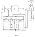
The function-block/signal-flow diagram in FIG. 2 represents two identical individual hearing aids of a hearing-aid set according to this invention. Function blocks shown in FIG. 1 bear the same reference numbers in FIG. 2. The microphone system 3 connects to the converter 7 via the signal processing unit 5. A selector switch 20 on the signal processing unit 5 permits the selection of at least two and preferably several transmission modes M1, M2 . . . Mx.
The transmission mode M currently to be enabled is manually selected on the selector switch assembly 20, shown in position S20, for instance by means of a toggle switch on the hearing aid or, wireless, via the remote control. In adaptation to the current acoustic environment, it is equally possible, as indicated by the dotted outline, to select the transmission mode M that is best for each prevailing acoustic-environment condition, by means of an evaluation unit 23 and the selector switch 20 on the hearing aid.
By way of example and as illustrated, the selector switch assembly 20 is provided with an identifier memory 25 in which the corresponding identifier Mx of the currently active transmission mode M is stored. The identifier memory 25 connects to a transmission/reception controller 27 with a transmitter/receiver assembly 29. When a second hearing aid, preferably identical in design to the one in FIG. 2, is to be synchronized, and assuming that the hearing aid shown in FIG. 2 is the master, the transmission/reception controller 27 will be triggered as indicated by S27 and will send the mode identifier Mx, stored in the identifier memory 25, to the other hearing aid via the transmitter/receiver 29 which now acts as the transmitter -O-. The other hearing aid receives the identifier Mx, its transmission/reception controller 27 stores it in its own identifier memory 25, whereby, as indicated by the bidirectional path S01, the selector switch assembly 20 is set according to the mode identifier received. The receiving hearing aid i.e. the slave, now operates in the same transmission mode Mx as the transmitting hearing aid, that being the master.
By activating or deactivating the signal input S27 which triggers this syhchronization process, one can specify which of the two hearing aids is to operate as the master and which as the slave.
As stated, the synchronization process in the master hearing aid can be triggered manually via S27, or automatically. If, as indicated by the dotted outline in FIG. 2, the evaluation unit 23, upon an analysis of the current acoustic environment, automatically causes a mode change in the hearing aid concerned by way of the selector switch assembly 20, a synchronizing process can be automatically triggered via the control input S27 either simultaneously or at a predetermined time interval. Of course, it is also possible (but not illustrated) to apply the synchronization trigger signal in the master hearing aid at the input S27 by means of a timer operating at preset time intervals.
Once the master and slave functions have been established, this master/slave approach requires only one-way communication between the hearing aids.
Building on the concept illustrated in FIG. 2 and essentially following the master/slave principle, FIG. 3 shows how at the point of synchronization the transmission mode of the master hearing aid need not be simply accepted but, instead, by employing for instance M′M, M′S an optimal constellation is selected on the basis of the current constellation of both transmission modes MMm, and MSm.
FIG. 3 only shows the function blocks and signal paths which differ from those of the hearing aid in FIG. 2. Connected to the transmitter/receiver 27 is a timer 37 which, activated in only one hearing aid and operating at preset time intervals, sends the currently enabled transmission mode MSm from the identifier memory 25 activated by this unit to the other unit. In contrast thereto, as schematically indicated by the switches W, a table memory 39 is activated in the other hearing aid, the master. The mode identifier MSm, sent by the slave in response to the transmission clock pulse of the timer 37, is stored in the table memory 39, as is the mode enabled by the currently valid identifier MMm, of the master. When, as described in reference to FIG. 2, the control signal S27 triggers a synchronization, whether manually or automatically, a constellation M′M/M′S which has been found to be optimal for the current constellation M′M/M′S is retrieved from the table in the table memory 39, M′M, and applied to the selector input S20, and M's is sent to the master for storage in the identifier memory 25 and for activating the corresponding mode.
As indicated in FIG. 3, synchronization can also be triggered automatically by the presence of preselected mode constellations, in addition to or in lieu of the automatic triggering on the basis of an analysis of the acoustic environment as shown in FIG. 2, or to/of manual actuation. In FIG. 3, the constellation MMm,=4, MSm,=1 triggers a synchronization process at S″27 the result being M′M=2 and M′S=2.
If both devices are configured identically, it is easy by virtue of the two constellations MMm′MSm′ to decide which hearing aid or which mode of the constellation is dominant, permitting instantaneous automatic assignment of the master/slave function. For example, mode 2 can be selected to dominate all others, 1, 3, 4, while 3 dominates modes 1 and 4. The device which is currently operating in the dominating mode will retain its mode or will adopt the master configuration described in reference to FIG. 3.
Moreover, the result of the acoustic environment analysis, obtained by means of unit 23 in FIG. 2, can be employed in addition to or perhaps in lieu of the instantaneous constellation MMm/MSm, for establishing the constellation M′M, M′S to be created upon synchronization. As a consequence, the table in the table memory 39 will take on another dimension or the characteristic value of the acoustic-environment evaluation will appear in the table instead of the instantaneous constellation MMm/MSm.
The method according to this invention makes it possible, with minimal additional electric power consumption, to mutually optimize the binaurally used hearing aids for the mode-identifier transmission at relatively large time intervals. The user is able at any time to manually and especially by way of the remote control break through the established synchronization; based on the operating principle of this invention as described, the synchronization can be restored or reestablished, a process which in the case of automatic restoration can be disabled by the user.

Claims (21)

1. A hearing device system comprising a first and a second hearing device and a communication link between said first and second devices, said communication link being operationally connected to at least one signal generating unit generating exclusively a signal to be transmitted via said communication link, said signal generating unit being a non-audio signal generating unit,
wherein said first and said second devices comprise one of said signal generating units, and at least one of said devices being switchable in situ in at least two transmission modes between a microphone arrangement and an output converter, the other of said devices having said signal generating unit generating a control signal for switching between said at least two transmission modes at said one device.
2. The system of claim 1, wherein both of said first and second devices are switchable in situ in at least two respective transmission modes between a respective microphone arrangement and a respective output converter, said signal generating unit generating a transmission mode synchronizing signal for synchronizing the transmission modes at said devices.
3. The system of claim 1, said control signal generated by said signal generating unit switching one of said devices to the transmission mode of the other of said devices or switching both devices to transmission modes different from transmission modes established at said devices prior to generation of said control signal.
4. The system of claim 1, wherein said signal generating unit is controlled by a signal from an acoustical environment analyzing unit.
5. The system of claim 1, wherein said communication link is a wireless communication link.
6. The system of claim 1, wherein said communication link is not connected to transmit audio signals.
7. A method for operating binaural hearing devices, each of said devices being selectively operable in situ in at least two transmission modes between a microphone arrangement and an output converter comprising the steps of
establishing a wireless communication link between the devices for transmitting control signals between the devices, wherein said control signals include signals for pairing the transmission modes of the devices,
at least one of the devices analyzing an acoustic environment, and
pairing the respective transmission modes of the devices by means of at least one of the control signals, as a function of a result of said analyzing, to an optimal mode constellation predetermined for the analyzed acoustic environment.
8. A method for operating binaural hearing devices, each of said devices being selectively operable in situ in at least two transmission modes between a microphone arrangement and an output converter comprising the steps of
establishing a wireless communication link between the devices for transmitting control signals between the devices, wherein said control signals include signals for synchronizing the transmission modes of the devices,
at least one of the devices analyzing an acoustic environment, and
synchronizing the respective transmission modes of the devices by means of at least one of the control signals, as a function of a result of said analyzing, to an optimal mode constellation predetermined for the analyzed acoustic environment.
9. A method for operating binaural hearing devices, each of said devices being switchable in situ in at least two transmission modes between a microphone arrangement and an output converter comprising the steps of
establishing a wireless communication link between the devices for transmitting control signals between the devices, wherein said control signals include signals for pairing the transmission modes of the devices,
at least one of the devices analyzing an acoustic environment, and
pairing the respective transmission modes of the devices by means of at least one of the control signals, as a function of a result of said analyzing, to an optimal mode constellation predetermined for the analyzed acoustic environment.
10. The method for operating binaural hearing devices, each of said devices being switchable in situ in at least two transmission modes between a microphone arrangement and an output converter comprising the steps of
establishing a wireless communication link between the devices for transmitting control signals between the devices, wherein said control signals include signals for synchronizing the transmission modes of the devices, and
synchronizing the respective transmission modes of the devices by means of the control signals, as a function of acoustic environment and predetermined optimal mode constellations.
11. The method of any one of claims 7-10, wherein said communication link is bidirectional.
12. The method of any one of claims 7-10, wherein one of said devices acts as a master, the second of said devices acts as a slave device with respect to said communication link.
13. A method according to any one of claims 7 and 9, wherein the step of pairing comprises balancing the transmission modes.
14. A method for operating binaural hearing devices at an individual, each of said devices being operable in at least two transmission modes between a microphone arrangement and an output converter respectively, comprising the steps of automatically analyzing an acoustical environment and controlling pairing of said transmission modes at said hearing devices in dependence of a result of said analyzing.
15. A binaural hearing device system comprising a first and a second hearing device and a communication link between said first and second devices, an assembly at each of said devices for controlling respectively each of said devices to operate in one of at least two signal transmission modes established between a microphone arrangement and an output converter respectively, said assemblies having a control input respectively, an acoustical environment analyzing unit with an output operationally connected to the control input of said assemblies so as to control mutual paring of said transmission modes at said hearing devices, wherein the communication link is connected to communicate information for mutual pairing of said transmission modes.
16. The system of claim 15 wherein the assemblies each comprise a selector switch for selecting the transmission mode.
17. The system of claim 15 wherein at least one of the control inputs is connected to be operated by the information communicated via said link.
18. The system of claim 15 wherein the information communicated via said link is dependent on the output of the acoustical environment analyzing unit.
19. The system of claim 15 wherein each hearing device further comprises a transmitter/receiver connected to transmit said information for mutual pairing.
20. The system of claim 15 wherein the information for mutual pairing includes a control signal transmission mode identifier.
21. The system of claim 20 wherein the assemblies each comprise a selector switch for selecting the transmission mode and each hearing device further comprises a transmitter/receiver connected to transmit said information for mutual pairing.
US10/842,270 1999-10-15 2004-05-10 Binaural synchronization Expired - Fee Related US7580535B2 (en)

Priority Applications (1)

Application Number Priority Date Filing Date Title
US10/842,270 US7580535B2 (en) 1999-10-15 2004-05-10 Binaural synchronization

Applications Claiming Priority (4)

Application Number Priority Date Filing Date Title
WOPCT/CH99/00488 1999-10-15
PCT/CH1999/000488 WO2000000001A2 (en) 1999-10-15 1999-10-15 Binaural synchronisation
US09/431,702 US6768802B1 (en) 1999-10-15 1999-11-01 Binaural synchronization
US10/842,270 US7580535B2 (en) 1999-10-15 2004-05-10 Binaural synchronization

Related Parent Applications (1)

Application Number Title Priority Date Filing Date
US09/431,702 Continuation US6768802B1 (en) 1999-10-15 1999-11-01 Binaural synchronization

Publications (2)

Publication Number Publication Date
US20040208332A1 US20040208332A1 (en) 2004-10-21
US7580535B2 true US7580535B2 (en) 2009-08-25

Family

ID=4551724

Family Applications (2)

Application Number Title Priority Date Filing Date
US09/431,702 Expired - Lifetime US6768802B1 (en) 1999-10-15 1999-11-01 Binaural synchronization
US10/842,270 Expired - Fee Related US7580535B2 (en) 1999-10-15 2004-05-10 Binaural synchronization

Family Applications Before (1)

Application Number Title Priority Date Filing Date
US09/431,702 Expired - Lifetime US6768802B1 (en) 1999-10-15 1999-11-01 Binaural synchronization

Country Status (8)

Country Link
US (2) US6768802B1 (en)
EP (1) EP1221277B1 (en)
JP (1) JP4336458B2 (en)
AU (1) AU774579B2 (en)
CA (1) CA2387669C (en)
DE (1) DE59913950D1 (en)
DK (1) DK1221277T3 (en)
WO (1) WO2000000001A2 (en)

Cited By (7)

* Cited by examiner, † Cited by third party
Publication number Priority date Publication date Assignee Title
US20070030988A1 (en) * 2005-08-04 2007-02-08 Robert Bauml Method for the synchronization of signal tones and corresponding hearing aids
US20070274550A1 (en) * 2006-05-24 2007-11-29 Phonak Ag Hearing assistance system and method of operating the same
US20100128907A1 (en) * 2007-01-22 2010-05-27 Phonak Ag System and method for providing hearing assistance to a user
US20100128906A1 (en) * 2006-12-20 2010-05-27 Phonak Ag Hearing assistance system and method of operating the same
US20110033073A1 (en) * 2009-05-25 2011-02-10 Junichi Inoshita Hearing aid system
US20110033071A1 (en) * 2003-06-06 2011-02-10 Gn Resound A/S Hearing aid wireless network
US20130308804A1 (en) * 2012-05-15 2013-11-21 Cochlear Limited Adaptive Data Rate for a Bilateral Hearing Prosthesis System

Families Citing this family (49)

* Cited by examiner, † Cited by third party
Publication number Priority date Publication date Assignee Title
US7206423B1 (en) * 2000-05-10 2007-04-17 Board Of Trustees Of University Of Illinois Intrabody communication for a hearing aid
DK1316240T3 (en) * 2000-07-14 2006-02-27 Gn Resound As A synchronized binaural hearing system
DE10048354A1 (en) * 2000-09-29 2002-05-08 Siemens Audiologische Technik Method for operating a hearing aid system and hearing aid system
US7254246B2 (en) 2001-03-13 2007-08-07 Phonak Ag Method for establishing a binaural communication link and binaural hearing devices
JP2004530310A (en) * 2001-03-13 2004-09-30 フォーナック アーゲー Method of forming a removable mechanical and / or electrical connection, a hearing device and a hearing device system using the method
DE10211364B4 (en) * 2002-03-14 2004-02-05 Siemens Audiologische Technik Gmbh Deactivating signal processing devices of a hearing aid
DE10304648B3 (en) 2003-02-05 2004-08-19 Siemens Audiologische Technik Gmbh Device and method for communicating hearing aids
CN103379418A (en) * 2003-06-24 2013-10-30 Gn瑞声达A/S A binaural hearing aid system with coordinated sound processing
US7257372B2 (en) * 2003-09-30 2007-08-14 Sony Ericsson Mobile Communications Ab Bluetooth enabled hearing aid
US7639827B2 (en) * 2003-10-01 2009-12-29 Phonak Ag Hearing system which is responsive to acoustical feedback
DE10351509B4 (en) * 2003-11-05 2015-01-08 Siemens Audiologische Technik Gmbh Hearing aid and method for adapting a hearing aid taking into account the head position
US7512383B2 (en) * 2003-11-26 2009-03-31 Starkey Laboratories, Inc. Transmit-receive switching in wireless hearing aids
US7283639B2 (en) * 2004-03-10 2007-10-16 Starkey Laboratories, Inc. Hearing instrument with data transmission interference blocking
US7443991B2 (en) * 2004-03-31 2008-10-28 Siemens Audiologische Technik Gmbh ITE hearing aid for binaural hearing assistance
DE102004035256B3 (en) 2004-07-21 2005-09-22 Siemens Audiologische Technik Gmbh Hearing aid system and method for operating a hearing aid system with audio reception
EP1624723B1 (en) 2004-08-02 2012-05-30 Siemens Audiologische Technik GmbH Stabilisation of the system-clock pulse in a hearing aid
US20080226103A1 (en) * 2005-09-15 2008-09-18 Koninklijke Philips Electronics, N.V. Audio Data Processing Device for and a Method of Synchronized Audio Data Processing
DE102005046169A1 (en) * 2005-09-27 2007-04-05 Siemens Audiologische Technik Gmbh Hearing aid with an antenna
EP1771038B2 (en) 2005-09-30 2013-02-27 Siemens Audiologische Technik GmbH Method for operating a hearing-aid system for binaural treatment of a user
US20070183609A1 (en) * 2005-12-22 2007-08-09 Jenn Paul C C Hearing aid system without mechanical and acoustic feedback
DE102006014022A1 (en) * 2006-03-27 2007-10-11 Siemens Audiologische Technik Gmbh Hearing aid system with binaural data logging and corresponding procedure
DE602006004016D1 (en) * 2006-05-24 2009-01-15 Phonak Ag Hearing aid system and method for its operation
DK2039218T3 (en) 2006-07-12 2021-03-08 Sonova Ag A METHOD FOR OPERATING A BINAURAL HEARING SYSTEM, AS WELL AS A BINAURAL HEARING SYSTEM
DE102007010601A1 (en) 2007-03-05 2008-09-25 Siemens Audiologische Technik Gmbh Hearing system with distributed signal processing and corresponding method
AT506055B1 (en) * 2007-04-30 2014-03-15 Cochlear Ltd SYNCHRONIZATION OF TWO-SIDED PROSTHESIS
DE102007046437B4 (en) * 2007-09-28 2009-07-30 Siemens Audiologische Technik Gmbh Fully automatic switching on / off for hearing aids
US8906700B2 (en) 2007-11-06 2014-12-09 Ambergen, Inc. Methods and compositions for phototransfer
US9886599B2 (en) 2008-04-02 2018-02-06 Yougetitback Limited Display of information through auxiliary user interface
US9916481B2 (en) 2008-04-02 2018-03-13 Yougetitback Limited Systems and methods for mitigating the unauthorized use of a device
JP2012529969A (en) 2008-08-01 2012-11-29 ロジャー・ピー・ジャクソン Longitudinal connecting member with tensioning cord with sleeve
DE102008064430B4 (en) 2008-12-22 2012-06-21 Siemens Medical Instruments Pte. Ltd. Hearing device with automatic algorithm switching
EP2757988A4 (en) 2009-06-15 2015-08-19 Jackson Roger P Polyaxial bone anchor with pop-on shank and winged insert with friction fit compressive collet
US9556059B2 (en) 2009-08-03 2017-01-31 Hong Li Glass compositions and fibers made therefrom
DK2346271T3 (en) * 2009-12-01 2014-08-04 Oticon As Control of operating parameters in a binaural listening system
US9693577B2 (en) 2010-01-29 2017-07-04 Abbott Laboratories Method of preparing a nutritional powder comprising spray dried HMB
DK3125578T3 (en) * 2010-11-17 2020-03-23 Oticon As WIRELESS BINAURAL HEARING SYSTEM
CA2822846C (en) 2011-02-02 2015-04-28 Widex A/S Binaural hearing aid system and a method of providing binaural beats
US8953810B2 (en) 2011-03-03 2015-02-10 Cochlear Limited Synchronization in a bilateral auditory prosthesis system
US9907582B1 (en) 2011-04-25 2018-03-06 Nuvasive, Inc. Minimally invasive spinal fixation system and related methods
US9439004B2 (en) 2012-02-22 2016-09-06 Sonova Ag Method for operating a binaural hearing system and a binaural hearing system
CZ24690U1 (en) 2012-10-25 2012-12-10 Rotor body for magnetic lifting device
US9471090B2 (en) 2012-11-21 2016-10-18 Starkey Laboratories, Inc. Method and apparatus for synchronizing hearing instruments via wireless communication
CN105189500A (en) 2013-02-13 2015-12-23 诺华股份有限公司 IP receptor agonist heterocyclic compounds
WO2014198323A1 (en) 2013-06-13 2014-12-18 Phonak Ag Method for operating a hearing system and a device of a hearing system
EP3798229A1 (en) * 2014-03-25 2021-03-31 Yale University Uses of parasite macrophage migration inhibitory factors
EP3134785B1 (en) 2014-04-24 2021-06-02 BAE Systems PLC Aircraft airframe assembly
EP3046338A1 (en) 2015-01-13 2016-07-20 Oticon Medical A/S Hearing aid system with an aligned auditory perception
DE102015216742A1 (en) 2015-09-02 2017-03-02 Schaeffler Technologies AG & Co. KG Roller element for a centrifugal pendulum device
DE102017215650A1 (en) 2016-09-08 2018-03-08 Magna Closures Inc. User indication of activation of a powered system during non-contact human activation

Citations (9)

* Cited by examiner, † Cited by third party
Publication number Priority date Publication date Assignee Title
US4425481A (en) 1981-04-16 1984-01-10 Stephan Mansgold Programmable signal processing device
US5434924A (en) 1987-05-11 1995-07-18 Jay Management Trust Hearing aid employing adjustment of the intensity and the arrival time of sound by electronic or acoustic, passive devices to improve interaural perceptual balance and binaural processing
WO1998016086A1 (en) 1996-10-10 1998-04-16 Alexandrescu Eugene Improved programmable hearing instrument and programming method thereof
US5757932A (en) 1993-09-17 1998-05-26 Audiologic, Inc. Digital hearing aid system
EP0941014A2 (en) 1998-03-03 1999-09-08 Siemens Audiologische Technik GmbH Hearing aid system with two hearing aid devices and method of operation of such an hearing aid system
US6148087A (en) 1997-02-04 2000-11-14 Siemens Augiologische Technik Gmbh Hearing aid having two hearing apparatuses with optical signal transmission therebetween
US6549633B1 (en) * 1998-02-18 2003-04-15 Widex A/S Binaural digital hearing aid system
US20040013280A1 (en) 2000-09-29 2004-01-22 Torsten Niederdrank Method for operating a hearing aid system and hearing aid system
US20040057591A1 (en) 2002-06-26 2004-03-25 Frank Beck Directional hearing given binaural hearing aid coverage

Patent Citations (11)

* Cited by examiner, † Cited by third party
Publication number Priority date Publication date Assignee Title
US4425481A (en) 1981-04-16 1984-01-10 Stephan Mansgold Programmable signal processing device
US4425481B1 (en) 1981-04-16 1994-07-12 Stephan Mansgold Programmable signal processing device
US4425481B2 (en) 1981-04-16 1999-06-08 Resound Corp Programmable signal processing device
US5434924A (en) 1987-05-11 1995-07-18 Jay Management Trust Hearing aid employing adjustment of the intensity and the arrival time of sound by electronic or acoustic, passive devices to improve interaural perceptual balance and binaural processing
US5757932A (en) 1993-09-17 1998-05-26 Audiologic, Inc. Digital hearing aid system
WO1998016086A1 (en) 1996-10-10 1998-04-16 Alexandrescu Eugene Improved programmable hearing instrument and programming method thereof
US6148087A (en) 1997-02-04 2000-11-14 Siemens Augiologische Technik Gmbh Hearing aid having two hearing apparatuses with optical signal transmission therebetween
US6549633B1 (en) * 1998-02-18 2003-04-15 Widex A/S Binaural digital hearing aid system
EP0941014A2 (en) 1998-03-03 1999-09-08 Siemens Audiologische Technik GmbH Hearing aid system with two hearing aid devices and method of operation of such an hearing aid system
US20040013280A1 (en) 2000-09-29 2004-01-22 Torsten Niederdrank Method for operating a hearing aid system and hearing aid system
US20040057591A1 (en) 2002-06-26 2004-03-25 Frank Beck Directional hearing given binaural hearing aid coverage

Non-Patent Citations (1)

* Cited by examiner, † Cited by third party
Title
WO/99/43185, Publication Date: Aug. 26, 1999, A Binaural Digital Hearing Aid System.

Cited By (14)

* Cited by examiner, † Cited by third party
Publication number Priority date Publication date Assignee Title
US8571241B2 (en) * 2003-06-06 2013-10-29 Gn Resound A/S Hearing aid wireless network
US20110033071A1 (en) * 2003-06-06 2011-02-10 Gn Resound A/S Hearing aid wireless network
US20070030988A1 (en) * 2005-08-04 2007-02-08 Robert Bauml Method for the synchronization of signal tones and corresponding hearing aids
US7844062B2 (en) * 2005-08-04 2010-11-30 Siemens Audiologische Technik Gmbh Method for the synchronization of signal tones and corresponding hearing aids
US20070274550A1 (en) * 2006-05-24 2007-11-29 Phonak Ag Hearing assistance system and method of operating the same
US7688991B2 (en) * 2006-05-24 2010-03-30 Phonak Ag Hearing assistance system and method of operating the same
US8081787B2 (en) * 2006-12-20 2011-12-20 Phonak Ag Hearing assistance system and method of operating the same
US20100128906A1 (en) * 2006-12-20 2010-05-27 Phonak Ag Hearing assistance system and method of operating the same
US20100128907A1 (en) * 2007-01-22 2010-05-27 Phonak Ag System and method for providing hearing assistance to a user
US8526648B2 (en) * 2007-01-22 2013-09-03 Phonak Ag System and method for providing hearing assistance to a user
US8050439B2 (en) 2009-05-25 2011-11-01 Panasonic Corporation Hearing aid system
US20110033073A1 (en) * 2009-05-25 2011-02-10 Junichi Inoshita Hearing aid system
US20130308804A1 (en) * 2012-05-15 2013-11-21 Cochlear Limited Adaptive Data Rate for a Bilateral Hearing Prosthesis System
US9020169B2 (en) * 2012-05-15 2015-04-28 Cochlear Limited Adaptive data rate for a bilateral hearing prosthesis system

Also Published As

Publication number Publication date
US20040208332A1 (en) 2004-10-21
WO2000000001A2 (en) 2000-01-06
DK1221277T3 (en) 2007-02-05
CA2387669A1 (en) 2000-01-06
EP1221277B1 (en) 2006-10-25
AU6075499A (en) 2000-01-17
EP1221277A2 (en) 2002-07-10
US6768802B1 (en) 2004-07-27
WO2000000001A3 (en) 2000-11-23
CA2387669C (en) 2010-12-14
JP2002542635A (en) 2002-12-10
AU774579B2 (en) 2004-07-01
DE59913950D1 (en) 2006-12-07
JP4336458B2 (en) 2009-09-30

Similar Documents

Publication Publication Date Title
US7580535B2 (en) Binaural synchronization
US11678128B2 (en) Method and apparatus for a binaural hearing assistance system using monaural audio signals
AU2005203093B2 (en) Hearing aid system and method for operating a hearing aid system for audio reception
DK176783B1 (en) Method of operation of a hearing aid and hearing aid device or hearing aid
EP0855130B1 (en) Digital hearing aid system
US6549633B1 (en) Binaural digital hearing aid system
US20060067549A1 (en) Method of operating a hearing aid system having at least two hearing aids
EP2119310B1 (en) System and method for providing hearing assistance to a user
EP2375786B1 (en) System for programming special function buttons for hearing assistance device applications
EP2705675B1 (en) Self-learning hearing assistance system and method of operating the same
DK1377118T3 (en) Hearing aid system with a hearing aid and an external processor unit
US8155359B2 (en) Hearing system with remote control as a base station and corresponding communication method
KR101605943B1 (en) Method and system for wireless communication between a telephone and a hearing aid
KR101630229B1 (en) Wireless communication type hearing aid
GB2391673A (en) Wireless Audio Voice Monitor using Variable Bandwidth
JP2002084589A (en) Acoustic reproducer

Legal Events

Date Code Title Description
FEPP Fee payment procedure

Free format text: PAYOR NUMBER ASSIGNED (ORIGINAL EVENT CODE: ASPN); ENTITY STATUS OF PATENT OWNER: LARGE ENTITY

STCF Information on status: patent grant

Free format text: PATENTED CASE

FPAY Fee payment

Year of fee payment: 4

AS Assignment

Owner name: SONOVA AG, SWITZERLAND

Free format text: CHANGE OF NAME;ASSIGNOR:PHONAK AG;REEL/FRAME:036674/0492

Effective date: 20150710

FPAY Fee payment

Year of fee payment: 8

FEPP Fee payment procedure

Free format text: MAINTENANCE FEE REMINDER MAILED (ORIGINAL EVENT CODE: REM.); ENTITY STATUS OF PATENT OWNER: LARGE ENTITY

LAPS Lapse for failure to pay maintenance fees

Free format text: PATENT EXPIRED FOR FAILURE TO PAY MAINTENANCE FEES (ORIGINAL EVENT CODE: EXP.); ENTITY STATUS OF PATENT OWNER: LARGE ENTITY

STCH Information on status: patent discontinuation

Free format text: PATENT EXPIRED DUE TO NONPAYMENT OF MAINTENANCE FEES UNDER 37 CFR 1.362

FP Lapsed due to failure to pay maintenance fee

Effective date: 20210825