US7489746B1 - MIMO receiver using maximum likelihood detector in combination with QR decomposition - Google Patents
MIMO receiver using maximum likelihood detector in combination with QR decomposition Download PDFInfo
- Publication number
- US7489746B1 US7489746B1 US11/112,068 US11206805A US7489746B1 US 7489746 B1 US7489746 B1 US 7489746B1 US 11206805 A US11206805 A US 11206805A US 7489746 B1 US7489746 B1 US 7489746B1
- Authority
- US
- United States
- Prior art keywords
- matrix
- distance
- wireless receiver
- signals
- channel
- Prior art date
- Legal status (The legal status is an assumption and is not a legal conclusion. Google has not performed a legal analysis and makes no representation as to the accuracy of the status listed.)
- Active, expires
Links
Images


Classifications
-
- H—ELECTRICITY
- H04—ELECTRIC COMMUNICATION TECHNIQUE
- H04L—TRANSMISSION OF DIGITAL INFORMATION, e.g. TELEGRAPHIC COMMUNICATION
- H04L25/00—Baseband systems
- H04L25/02—Details ; arrangements for supplying electrical power along data transmission lines
- H04L25/0202—Channel estimation
- H04L25/024—Channel estimation channel estimation algorithms
- H04L25/0242—Channel estimation channel estimation algorithms using matrix methods
- H04L25/0246—Channel estimation channel estimation algorithms using matrix methods with factorisation
-
- H—ELECTRICITY
- H04—ELECTRIC COMMUNICATION TECHNIQUE
- H04B—TRANSMISSION
- H04B7/00—Radio transmission systems, i.e. using radiation field
- H04B7/02—Diversity systems; Multi-antenna system, i.e. transmission or reception using multiple antennas
- H04B7/04—Diversity systems; Multi-antenna system, i.e. transmission or reception using multiple antennas using two or more spaced independent antennas
- H04B7/0413—MIMO systems
-
- H—ELECTRICITY
- H04—ELECTRIC COMMUNICATION TECHNIQUE
- H04B—TRANSMISSION
- H04B7/00—Radio transmission systems, i.e. using radiation field
- H04B7/02—Diversity systems; Multi-antenna system, i.e. transmission or reception using multiple antennas
- H04B7/04—Diversity systems; Multi-antenna system, i.e. transmission or reception using multiple antennas using two or more spaced independent antennas
- H04B7/08—Diversity systems; Multi-antenna system, i.e. transmission or reception using multiple antennas using two or more spaced independent antennas at the receiving station
- H04B7/0837—Diversity systems; Multi-antenna system, i.e. transmission or reception using multiple antennas using two or more spaced independent antennas at the receiving station using pre-detection combining
- H04B7/0842—Weighted combining
- H04B7/0848—Joint weighting
- H04B7/0851—Joint weighting using training sequences or error signal
-
- H—ELECTRICITY
- H04—ELECTRIC COMMUNICATION TECHNIQUE
- H04B—TRANSMISSION
- H04B7/00—Radio transmission systems, i.e. using radiation field
- H04B7/02—Diversity systems; Multi-antenna system, i.e. transmission or reception using multiple antennas
- H04B7/04—Diversity systems; Multi-antenna system, i.e. transmission or reception using multiple antennas using two or more spaced independent antennas
- H04B7/08—Diversity systems; Multi-antenna system, i.e. transmission or reception using multiple antennas using two or more spaced independent antennas at the receiving station
- H04B7/0837—Diversity systems; Multi-antenna system, i.e. transmission or reception using multiple antennas using two or more spaced independent antennas at the receiving station using pre-detection combining
- H04B7/0842—Weighted combining
- H04B7/0848—Joint weighting
- H04B7/0854—Joint weighting using error minimizing algorithms, e.g. minimum mean squared error [MMSE], "cross-correlation" or matrix inversion
-
- H—ELECTRICITY
- H04—ELECTRIC COMMUNICATION TECHNIQUE
- H04L—TRANSMISSION OF DIGITAL INFORMATION, e.g. TELEGRAPHIC COMMUNICATION
- H04L1/00—Arrangements for detecting or preventing errors in the information received
- H04L1/02—Arrangements for detecting or preventing errors in the information received by diversity reception
- H04L1/06—Arrangements for detecting or preventing errors in the information received by diversity reception using space diversity
-
- H—ELECTRICITY
- H04—ELECTRIC COMMUNICATION TECHNIQUE
- H04L—TRANSMISSION OF DIGITAL INFORMATION, e.g. TELEGRAPHIC COMMUNICATION
- H04L25/00—Baseband systems
- H04L25/02—Details ; arrangements for supplying electrical power along data transmission lines
- H04L25/03—Shaping networks in transmitter or receiver, e.g. adaptive shaping networks
- H04L25/03006—Arrangements for removing intersymbol interference
- H04L2025/0335—Arrangements for removing intersymbol interference characterised by the type of transmission
- H04L2025/03426—Arrangements for removing intersymbol interference characterised by the type of transmission transmission using multiple-input and multiple-output channels
Definitions
- Wireless networks have become increasingly popular, as computers and other devices can be coupled for data communications without requiring wired connections between the network nodes.
- One set of standards for wireless networks is the IEEE 802.11 standards, but other wireless standards or protocols might be used instead. Because wireless networks are expected to operate in unfavorable conditions, such as in the presence of reflections, interference, movement of receivers/transmitters, etc., much effort is needed to correctly transmit and receive data over a wireless channel.
- a typical node in a wireless network includes a receive chain and a transmit chain.
- a transmit chain typically includes some digital processing and analog circuitry (RF, baseband, etc.) that causes a signal to be transmitted into the wireless channel.
- a receive chain typically includes one or more antenna, RF circuitry and other analog circuitry, and digital processing that seeks to output a data stream that represents what the sending transmit chain received as its input and transmitted into the wireless network.
- RF radio frequency
- the receive chain includes various components designed to ensure that signals can be largely recovered correctly.
- MIMO multiple-input, multiple-output
- MLD maximum likelihood detector
- IEEE 802.11 there are at least two widely-used standards, 802.11a and 802.11b, and communication systems and devices might be required to support both standards and/or be required to operate in areas where both are being used. Enhancements to the 802.11 standards have been in place, such as the 802.11g standard that allows for OFDM transmissions (802.11a is an OFDM transmission protocol) in the 2.4 GHz band.
- the 802.11a protocol supports OFDM transmissions in the 5 GHz band for data rates of 6 to 54 million bits per second (“Mbps”).
- the 802.11b protocol supports DSSS transmissions in the 2.4 GHz band for data rates of 1, 2, 5.5 and 11 Mbps.
- the 802.11g protocol mixes OFDM and DSSS protocols in the 2.4 GHz band for data rates of 1, 2, 5.5, 6, 9, 11, 12, 18, 24, 36, 48 and 54 Mbps. Data transmissions are well known for these protocols, so they need not be set forth herein. They are described, for example, in ANSI/IEEE Std 802.11, 1999 Edition; IEEE Std 802.11b, 1999; IEEE Std 802.11a, 1999/Amd 1:2000(E). Those references are incorporated by reference herein for all purposes.
- a MIMO system comprises at least a transmitter that transmits a number of bits, or a stream of bits, over a transmission medium to a receiver.
- the transmission medium is a wireless radio channel but the other media such as multi-mode fiber might be used instead.
- an MIMO transmitter transmits its data as M streams and a receiver processes its inputs as N inputs.
- a MIMO transmitter might comprise an encoder that first applies a forward error correcting (FEC) code on the bit stream that is to be received at an output of the receiver.
- the FEC code could be a block code, a convolution code or other code or codes.
- the distributed, coded transmit streams are modulated and transmitted.
- bits for a transmit stream might be divided in groups of two bits and modulated onto a carrier using QPSK (Quaternary Phase Shift Keying) modulation, which maps the bits onto complex transmit symbols as shown in Table 1.
- QPSK Quadrature Keying
- More or less advanced modulation techniques are possible, such as BPSK (mapping one bit at a time), 16-QAM (mapping groups of four bits), 64-QAM (mapping groups of six bits), etc.
- a MIMO transmitter transmits M ⁇ (log 2 c) bits per symbol period, whereas a single antenna system transmits (log 2 c) bits per symbol period.
- the transmit symbol for a particular symbol period on a transmit antenna i is denoted as x i .
- the transmit symbols for a symbol period can be represented as an M-dimensional vector x. These symbols are up-converted to radio frequency, transmitted and then received by N antennas at the receiver.
- the receiver converts the signal down to baseband frequency and, at the output of the N down-converters, N received symbols denoted as y 1 through y N are available. Those received symbols can be represented by an N-dimensional vector y.
- the current received symbol vector (i.e., the symbols received in a current symbol period at the receiver) can be represented as a function of the current transmitted symbol vector as shown in Equation 1 and expanded in Equation 2.
- scalar values are represented herein by normal characters
- vectors are represented herein by bolded lowercase characters
- matrices are represented herein by uppercase bolded characters.
- the scalar values and the components of the vectors and matrices can be real or complex values, unless otherwise indicated.
- a maximum likelihood detector can be used with an FEC decoder to decode transmissions.
- a detector might provide hard decisions (in the case of a detector with hard decision outputs) or soft decisions (in the case of a soft decision output detector) to an FEC decoder, which would then perform the inverse of what an encoder did to the data prior to transmission and, when there are no unrecoverable errors, the FEC decoder outputs what was input to the encoder.
- the detector combines received symbols and either estimates the transmitted bits to provide a hard decision (e.g., a “1” or a “0”) or produces a soft decision value for each transmitted bit representing a measure for the probability that the transmitted bit is “1” (or “0”). By quantizing the soft decision values, the soft decision detector is reduced to a hard decision detector.
- a hard decision e.g., a “1” or a “0”
- a soft decision value for each transmitted bit representing a measure for the probability that the transmitted bit is “1” (or “0”).
- a hard-decision detector operates over a MIMO channel characterized by (M, N, c), i.e., a MIMO system with M transmit antennas (possibly comprising polarizations), N receive antennas (possibly comprising polarizations) and a constellation of size c.
- M transmit antennas
- N receive antennas
- a constellation of size c i.e., a MIMO system with M transmit antennas (possibly comprising polarizations), N receive antennas (possibly comprising polarizations) and a constellation of size c.
- H Typically, packets are preceded by a known training waveform that can be used by the receiver to estimate H to within some estimation accuracy. Other techniques for estimating H in packet-based communication are possible. For non-packet-based communication, mid-ambles and other techniques to estimate H exist.
- Equation 3 The vector, ⁇ circumflex over (x) ⁇ , representing the most likely transmit vector x given what was received, can be represented as shown in Equation 3, wherein where X is the set (of size c M ) of all possible transmit vectors x.
- the detector finds the most probably transmitted transmit vector ⁇ circumflex over (x) ⁇ by finding the valid transmit vector that is “closest” to the received symbol vector y given the known channel characteristics from H.
- the receiver can output that as a hard decision for each of the bits of the transmit vector. Since each element of x is chosen from a set of c possible constellation values, the expression of Equation 4 needs to be evaluated c M times to determine the most probably transmitted transmit vector. Thus, computational complexity for determining the most probably transmitted transmit vector grows exponentially (proportional to c M ) with the number of transmit antennas (M), thus for larger values of c and M, the number of operations and calculations to decode the symbols represented by the vector x becomes prohibitive.
- computational complexity refers to a measure of the computational effort required to arrive at a result, usually measurable by some combination of the number of operations needed to be performed for each calculation and the number of calculations needed (actually or on average) to reach the result.
- the operations can be software operations or hardware operations, or a combination, such as real or complex, fixed point or floating point, additions or multiplications.
- Computational complexity could correspond to the number of operations needed for computing a result, such as the average number of additions and multiplications needed.
- Computational complexity can be reduced by reducing the number of operations needed for each calculation or the nature of the operations (e.g., replacing a multiplication with an addition reduces complexity).
- Computational complexity can also be reduced by reducing the number of calculations needed.
- Equation 4 if the expression of Equation 4 can be evaluated fewer than c M times, computational complexity will be reduced from the case where the expression is evaluated c M times even if the number of operations needed for each evaluation does not change. In addition, if the number of operations needed for each evaluation is reduced, computational complexity will be reduced further. Computational complexity can also be reduced by simplifying the individual operations, such as multiplying lower resolution values relative to the increased computational complexity of multiplying higher resolution values.
- a soft decision detector determines, for each bit of the transmitted transmit vector, a measure for the probability (the so-called log-likelihood ratio) that the transmitted bit was a “1” (or “0”), or does so for a collection of bits.
- the soft decision values provided by the soft decision detector can be quantized to reduce the result to hard decisions, or some other processing can be done to collectively reduce the result to hard decisions, such as using a trellis decoder.
- the detector might find soft values for each bit b j according to Equation 5, where L(b i ) represents the probability that b 1 was “1” at the transmitter and ⁇ 2 is the power of the noise added on each antenna E ⁇ n i *n i ⁇ , where n 1 , . . . , n N , are stochastic variables with Gaussian distribution as introduced in Equation 2.
- Equation 5 The expression of Equation 5 can be approximated by the expression of Equation 6.
- S(t, z) denotes the slicing operation, with a grid spacing equal (or proportional) to t.
- the grid spacing is used to either divide z by t, after which it is compared to a set of fixed constellation thresholds, or alternatively, to multiply the constellation thresholds by t.
- the soft values for all bits can be computed from the distance values d[x 1 , x 2 , x M ⁇ 1 ], except the bits in transmit symbol x M .
- To obtain the soft values for the bits in x M the above process is repeated, but with a symbol other than x M excluded from the loop.
- the soft values for x M can be obtained from d[x 2 , x 3 , . . . , x M ] calculated in the second pass of the subset search process.
- Vaton describes an exact ML detection technique with a computational complexity roughly equivalent to that of the decorrelator at usual SNRs for CDMA systems operation.
- Detection comprises two steps: (i) first, a QR decomposition of the matrix of users' signatures is performed for multi-user detection and (ii) the detection is performed as an optimal path selection in a tree diagram.
- Vaton thus proposes QR preprocessing for maximum likelihood detection, wherein QR decomposition can be used to transform the MLD equations in a form that allows a tree formulation of the detection problem. It then discusses how two known tree search algorithms can be used to find a solution close to the optimal (“maximum likelihood, or “ML”) solution.
- ML maximum likelihood
- QR decomposition (sometimes referred to as “QR factorization”) is a well-known technique and can be used to transform a channel matrix into an upper triangular matrix.
- Q is unitary
- R can be found by multiplying the conjugate transpose Q* by H.
- Q* rotates the vectors H 1 and H 2 such that H 2 is in the xy-plane and H 1 lies along the x-axis.
- V-BLAST uses QR decomposition and provides a lower computational complexity than ML detection, but at the price of a lower performance.
- An example of such a decoding process would involve factoring H into Q and R and then searching over all possible combinations of the input symbols. Since V-BLAST selects input symbols one-by-one, this can be a source of inaccuracy that might need to be addressed in receiver designs.
- a MIMO receiver is provided with a preprocessor for performing full or partial QR decomposition of a channel matrix H wherein the factored reduced matrix R is used in place of H and Q*y is used in place of the received vector y in a maximum likelihood detector (“MLD”) for a reduction in the computational complexity of computing shortest distances.
- MLD maximum likelihood detector
- R might be an upper right triangular matrix and Q a unitary matrix.
- the maximum likelihood detector might be a hard-decision MLD or a soft-decision MLD.
- the MLD might use approximations in calculating distances, for example.
- MLD approximations include finite resolution calculations (fixed point or the like) or L1 Norm approximations.
- reduced matrix results fewer operations are needed in each distance calculation, so any approximations or limits on resolution of the calculations will accumulate over fewer operations, resulting in improved approximations.
- Other methods of reducing the channel matrix might be used for suitable and/or cumulative advantages, such as partial QR decomposition, Gramm-Schmidt orthogonalizations, Householder transforms, and Given's rotations.
- the received input signals could be received using distinct antennas and/or using polarization or other techniques to receive and/or transmit more than one stream over a given antenna.
- the number of receive antennas might be less than, equal to, or greater than three.
- the number of transmit antennas might be less than, equal to, or greater than the number of receive antennas.
- the channel matrix might be determined at the receiver by receiving a training signal and processing the training signal at the receiver.
- the channel is typically a wireless channel, but the receiver might also be implemented to receive signals over a constrained channel, such as a fiber optic channel.
- a subset search might be included in a detection process, for further reduction of computational complexity.
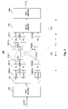
- FIG. 1 is a block diagram of a MIMO system in which aspects of the present invention might be used.
- FIG. 2 illustrates one model of a conventional MIMO MLD.
- FIG. 3 is a block diagram of a MIMO MLD according to aspects of the present invention, including a QR preprocessor.
- FIG. 4 is a block diagram of one example implementation of the QR preprocessor of FIG. 3 in greater detail.
- FIG. 5 is a block diagram of a complex CORDIC circuit usable in the factorizer shown in FIG. 4 .
- FIG. 6 is a block diagram of a CORDIC circuit for transforming rotations on arbitrary vectors.
- FIG. 7 illustrates one arrangement of CORDIC operations in a pipelined structure.
- FIG. 8 illustrates a floating point implementation of an optimized QR decomposition process.
- FIG. 9 is a plot of results from a performance simulation.
- FIG. 10 is a plot of results from a performance simulation using an MLD and FEC for a multi-path propagation channel
- FIG. 11 is a plot of results from a performance simulation using an MLD and FEC for a zero delay spread channel.
- FIG. 12 is an illustration of a slicing process.
- FIG. 13 is an illustration of a calculation process.
- QR decomposition is used to reduce the number of operations required for detection. As a side effect, some approximations used in computation become less significant, thereby providing higher performance for a given level of precision or comparable performance using lower levels of precision.
- Reducing computational complexity can relieve design constraints and/or allow for improved performance. For example, with reduced computational complexity, received signals can be processed faster for a given amount of hardware thus allowing higher data rates and, for a given data rate, received signals can be processed using less hardware, less power or fewer processing steps. In some instances, computational complexity can be reduced without affecting the resolution of the results, thus not lowering performance. Thus, a savings of computational complexity can be used to provide comparable results more quickly, using less circuitry, and/or requiring less consumed energy, or performance can be improved for a fixed amount of time, circuitry and/or energy.
- ASIC application specific integrated circuit
- area usage and power consumptions can be expected to be reduced for a reduction in the computational complexity.
- a single adder can be used repetitively to do many additions and computational complexity reduction allows for a lesser number of additions in a given time, which means less activity for the hardware adder and thus less power consumption.
- each addition can be done by a dedicated adder and reduction of computational complexity means that fewer adders are needed, and thus less area is needed so a receiver could be implemented in a smaller chip with less power being consumed.
- the search space of considered transmitted signals can be less than all the possible transmitted signals.
- the set of all possible transmit vectors has c M members.
- the plurality of considered transmitted signals i.e., the possible transmitted signals that are considered
- the signals of one of the transmit antennas can be assumed and a search performed over the subset of c (M ⁇ 1) possible signals from the remaining M ⁇ 1 transmit antennas, reducing the number of calculations by an order of c. This is often referred to as a “subset search”.
- Another technique for complexity reduction is to reduce the number (and/or type) of operations for each of the calculations of distance metrics or other calculations that are part of a computation.
- a computation of a result is a process involving several calculations and can have complexity that is dependent on the number of calculations as well as the complexity of each of the calculations. For some computations, the number of calculations might vary, as the result might be obtained early or late, so designs might be according to a complexity metric that is proportional to an average number of calculations.
- One example of reduction is the use of QR transformations as described herein. As noted herein, the use of QR transformations in combination with calculation approximations, such as reducing the number of operations for each calculation by using L1 Norms for distances, results in more accurate results because there is less opportunity for rounding errors to accumulate.
- a calculation can be the evaluation of an equation, comprising several operations. As used herein, in operation might be considered as a single cycle, such as an addition or multiplication, real or complex, fixed point or floating point. The boundaries between computations, calculations and operations need not be precise.
- Complexity reduction can be obtained by reducing the number of calculations needed for a computation, as well as by reducing the number of operations needed for each or some of the calculations. Complexity reduction can also be obtained by reducing the work done in each operation, such as by using rounding in operations. For example, fixed point numbers could be used in multiplication or addition operations to simplify the operations.
- QR decomposition can be used to reduce the number of operations required for maximum likelihood detection in a MIMO receiver.
- a number of types of calculations can be simplified and one example is calculations of distance vectors in either a hard-decision based detector or a soft-decision based detector.
- Equation 9 Equation 9
- the unitary matrix Q can be obtained from a factorization of the channel matrix H into a Q and an R component. From Q, Q* can be obtained by conjugating all the elements of Q and transposing the resulting matrix. To obtain y′, each received symbol y is rotated by left-multiplying it by Q*. Then, for an MLD process, such as one described herein or elsewhere, matrix R takes the role of H and y′ takes the role of y, and the rest of the process can remain unchanged.
- R contains a number of elements that are zero (every term beyond the upper triangular) and a number of elements that are real (the diagonal terms), the number of operations to evaluate d[x] using R is less than if H were used. With fewer operations, computation can be done faster and/or using less computing effort. In addition to the computational savings, use of the techniques described above results in improved accuracy, particularly where approximations are involved. Since calculations are necessarily done with a finite precision, when there are fewer operations, there is less accumulation of rounding errors, thereby improving accuracy of the calculations. If intentional approximations are used other than rounding, there would also be less accumulation of such approximations.
- the computational complexity of calculating d[x] can be independent of N (the number of receive antennas), as described below, for example, with reference to Equations 10-12. If the computational complexity is independent of N, the number of receive antennas can be increased to improve the receiver sensitivity without requiring extra computational effort. While the QR decomposition itself and the Q* pre-multiplication of y may require more operations for larger number of receive antennas, the number of operations required is typically much smaller than the number of operations required to calculate all d[x] values.
- FIG. 1 is a block diagram of a MIMO system 100 in which aspects of the present invention might be used.
- bits to be transmitted via a channel are provided to a FEC encoder 102 that applies a forward error correcting code and provides the encoded data to a de-multiplexer 104 that distributes its input into M transmit streams.
- Each transmit stream is modulated by a modulator 106 and passed to a transmission circuit 108 that transmits the modulated transmit stream using an antenna 110 into a channel 120 , such as a wireless radio space using some frequency band, such as those used for 802.11 transmissions.
- antennas 110 are distinct and spatially separated antennas.
- distinct signals might be combined into different polarizations off of fewer than M antennas.
- a receiver 125 receives signals from channel 120 at N antennas 130 (counting separate polarizations, as appropriate) coupled to N receive circuits 132 .
- the outputs of receive circuits 132 are provided to a MIMO detector 134 , which provides its output to a FEC decoder 136 , which in turn outputs the received bits which, without unrecoverable errors, are the same as the transmitted bits input to FEC encoder 102 .
- FIG. 2 illustrates one model of a conventional MIMO ML detector, where the inputs to the detector comprise a channel estimate, H, an N-dimensional received symbol, y, and where the output of the detector comprises M ⁇ (log 2 c), where c is the constellation size and M is the number of transmit antennas. H typically, but not necessarily, remains constant for the duration of a data packet, whereas y can be expected to change each symbol period.
- the M ⁇ (log 2 c) bit outputs are bits (e.g., “0” or “1”) and where the detector does soft-decision detection, the M ⁇ (log 2 c) bit outputs are soft-decision values.
- FIG. 3 illustrates a MIMO ML detector 300 according to aspects of the present invention.
- a QR preprocessor 302 receives the channel estimate H and factors H into Q and R and outputs R. QR preprocessor 302 conjugates Q to produce Q*, which a multiplier 304 multiplies with the received symbol vector y to arrive at y′.
- the matrix R and the vector y′ are provided as inputs to an MLD processor 310 .
- MLD processor 310 is constructed as described herein, but other implementations of an MLD processor could be used instead.
- An MLD processor that is configured to receive a channel estimate H matrix and a received symbol vector y can be used without modification, supplying instead the matrix R and the vector y′, respectively.
- FIG. 4 illustrates one example implementation of QR preprocessor 302 in greater detail.
- QR preprocessor 302 receives channel estimate matrix H and provides it to a factorizer 400 that generates matrices Q and R.
- Data representing matrix Q is provided by factorizer 400 to a conjugator 402 , which generates data representing the conjugate of matrix Q, namely the matrix Q*.
- the MLD processor might be modified from the conventional processor to take into account this reduced computation requirement.
- the MLD processor might be modified to use higher precision values for some calculations, might be modified to perform more operations in a given time, or other enhancements.
- the performance of the receiver might be improved in that for finite precision implementations, the soft values are more accurate because less finite arithmetic is being performed, which translates to a better performing, more robust communications system.
- Equation 10 the distance metric d[x] can be represented as shown in Equation 10.
- the vector z is a function of x and other quantities known to the receiver (R, y), so z is expressed in Equation 10 as a function of x.
- Equation 10 simplifies to Equation 11, which further simplifies to Equation 12, where K is a constant that is independent of x.
- K is a constant that is independent of x, it does not play a role in determining the minimum of ⁇ y′ ⁇ Rx ⁇ for hard-decision detection and in the expression for the computation of the soft value, the K terms in the two minima terms cancel each other out.
- Equation 14 only the r 12 x 2 element requires complex multiplication, whereas Equation 13 requires six complex-by-complex multiplications. Also, one real addition is needed, instead of three complex additions (i.e., six real additions). This savings is obtained for each d[x] value that needs to be calculated for each new symbol y.
- a QR preprocessor requires some added computation. However, the computation needed to perform QR decomposition need only be done once per packet (or after each change of the channel matrix, if that occurs more frequently), amortizing that extra computation over many symbols.
- the preprocessing step y′ Q*y adds six complex multiplications per symbol, but only once per symbol and not for each d[x] value. Note that, in this example, the value of y′ 3 is irrelevant because it only contributes to constant term K.
- QR preprocessing for an ML detector that may evaluate d[x] values for each of the c M possible values of x.
- QR preprocessing can also be used with “subset search” ML detectors that search over solution sets smaller than c M or search over the solution set in various passes to reduce computational complexity.
- subset search ML detectors that search over solution sets smaller than c M or search over the solution set in various passes to reduce computational complexity.
- QR preprocessing helps to reduce computational complexity and makes the resulting system more precise, which translates to a more robust link, with fewer bit errors.
- the computational complexity of the process is dominated by the inner loop of the algorithm, which has 2 B iterations (where B is the number of bits in the constellation, so 2 B is the number of constellation points).
- Each pass of the inner loop comprises one complex subtraction to compute z, B comparisons (equivalent to B real subtractions) to slice, 2N real additions to approximate the norm and 2N complex subtractions to compute the distance vector d[x 1 ].
- the total complexity measured relative to one real addition is about the same as 2+B+6N real additions for the x 1 loop.
- R 1 and R 2 i.e., the channel vectors represented in the Q coordinate system
- Received symbol y can be first multiplied by Q* to yield y′. Since Q* is unitary, i.e., it is norm preserving, noise on y is not enhanced, it merely gets rotated.
- the problem can be represented in base Q, wherein the “per symbol” loop (again, only the x 1 loop is shown) would be as follows:
- each iteration only requires one complex subtraction to compute z, B comparisons (equivalent to B real subtractions) to slice, four real additions to approximate the (partial) norm and three complex subtractions to calculate the distance vector.
- QR decomposition There are many algorithms to perform QR decomposition, including Gramm-Schmidt, Householder and Givens rotations. Below, one such method is given, based on Givens' rotations, which is practical to implement in hardware. If should be understood that other implementations might work as well.
- QR decomposition of an arbitrary sized matrix can be decomposed in a number of 2 ⁇ 1 QR decompositions. Specifically, this involves determining a 2 ⁇ 2, unitary matrix, T, that rotates any complex 2 ⁇ 1 vector (x y) T to a real vector with a zero second component, such as that shown in Equation 16.
- the matrix T can be split into a real matrix and a complex diagonal matrix as follows, where a and b are real numbers and c and d are complex numbers with modulus 1.
- T compl transforms the x and y components to real numbers without changing their moduli.
- T real rotates the two-dimensional real vector until it lies on the x-axis.
- a is the cosine of the angle of the real vector and b is the sine.
- This transform which rotates any complex vector, is the generalization of a CORDIC (“COordinate Rotation Digital Computer”) rotor, such as described in Volder, J., The CORDIC Trigonometric Computing Technique , IRE Trans. Comput., pp. 330-334 (September 1959).
- a CORDIC rotor rotates two-dimensional real vectors.
- a complex CORDIC 500 can be built using three real CORDICs 502 .
- the CORDICs are used in a mode (rotate-and-store, also called vectoring) where they rotate the output vector forcing the second input to zero and store the angle (or alternatively, a binary vector denoting a sequence of clockwise and counter-clockwise micro-rotations).
- the stored angle can be read back and applied on arbitrary inputs to apply the exact same rotation.
- the latter mode is called read-and-rotate (also called rotation).
- Each complex CORDIC stores three angles, ⁇ 1 , ⁇ 2 and ⁇ 3 , corresponding to arg(x), arg(y) and arctan(
- FIG. 6 illustrates how these stored angles can then be applied to four real CORDICs to apply the same rotation to an arbitrary vector (x, y).
- a QR decomposition of a 3 ⁇ 2 QR decomposition can be done with five complex CORDIC operations; three of the rotate-and-store type and two of the read-and-rotate type.
- the CORDICs are applied on subsets (indicated by the curly brackets) of the channel matrix as follows:
- FIG. 7 illustrates one arrangement 700 of three CORDIC operations in a pipelined structure (a systolic array) comprising two vectoring (V) CORDICs 702 , 703 and one rotating (R) CORDIC 704 .
- FIG. 7 actually shows five CORDICs, where the leftmost three ( 702 , 703 , 704 ) are used for the QR decomposition itself, while the rightmost two CORDICs ( 706 , 707 ) are used to rotate vector y.
- a single (complex) CORDIC can be reused to reduce the amount of hardware required. For minimum latency, five CORDICs can be used in parallel. For an intermediate solution, partial parallelism can be done using more than one CORDIC but less than five. To compare the amount of circuitry needed for a CORDIC rotator and a complex multiplier, three complex CORDICs require roughly the same circuitry components as six complex multipliers.
- FIG. 8 illustrates a floating point implementation of an optimized QR decomposition process.
- the implementation is described using pseudo C++ instructions in the figure, but it should be understood that other programming languages could be used to generate the instructions.
- the instructions in this process might be stored in an instruction memory within the receiver and executed by a general purpose processor within the receiver or executed by a processor configured to sequentially process instructions dedicated to the QR decomposition process.
- One important aspect of the process invokes complex and real CORDIC functions.
- FIG. 9 shows results from a first performance simulation considering just the MLD.
- No FEC decoder is used; the bits are decoded by slicing the soft decision outputs (i.e., a decoded bit is “1” if the soft value is larger than 0, and the decoded bit is “0” if the soft value is less than 0.
- Data is transmitted in packets of 48 symbols. 64-QAM modulation is used, so each symbol codes for six bits, and thus the entire packet codes for 288 bits. The channel may change between packets.
- FIG. 9 shows the Packet Error Rate (or “PER”; i.e., the probability that one or more of the bits in a packet is in error) for different signal-to-noise ratios (SNR) for different cases (QR preprocessing used/not used, exact L2 Norm vs. approximate L1 Norm).
- the signal-to-noise ratio is calculated as the ratio of the signal power to noise power.
- Equation 9 relies on the equality shown in Equation 8 and that is only true if the L2 Norm is used, Equation 9 is not exactly an equality if other norms are used.
- the performance optimality of MLD assumes the L2 Norm is used.
- FIGS. 10-11 illustrate results for more realistic simulations.
- a MIMO OFDM system including a soft-decision FEC decoder are modeled and channel estimation is done based on a training preamble and other real-world effects are modeled and taken into account.
- “float” and “fix” curves are shown, representing floating point results and fixed point results respectively.
- the propagation channel can be simulated more realistically by modeling multi-path propagation.
- the simulations use the L1 Norm approximation for vector length.
- Resolution of fixed-point calculations might be selected according to design constraints balancing speed increases of lower resolutions versus bit error rate increases due to lower resolution, possibly also taking into account power limitations and decoding time constraints.
- FIG. 10 shows the results for a multi-path propagation channel of 25 ns
- FIG. 11 shows the same simulations for a zero delay spread channel (also called Average White Gaussian Noise, or AWGN, channel).
- AWGN Average White Gaussian Noise
- FIG. 10 demonstrates that the fixed point implementation has a small performance loss compared to the floating point implementation.
- the QR preprocessor improves both the fixed and floating point performance by up to 0.5 dB. The main reason for this because the precision of the L1 Norm calculation after QR preprocessing is improved.
- the fixed point implementation benefits more from QR preprocessing than the floating point implementation, as the QR preprocessing also provides a method of reducing the impact of fixed point approximation errors, simply because fewer operations need to be done and accumulation of quantization and rounding errors is reduced.
- FIG. 11 confirms the results illustrated in FIG. 10 , although the benefits are smaller in an AWGN channel than in a multi-path channel.
- the QR processor itself has infinite precision. When QR preprocessing is performed by a fixed point arrangement, additional performance loss will result. This loss can be controlled by using sufficient resolution for the QR preprocessor. The impact of using high resolution is limited since the computational complexity needed to perform the QR preprocessing step using the preprocessor is small compared to that needed by the MLD to do its ML detection.
- Equ. 33 Equ. 33′
- the new EV ⁇ (u) function (EV stands for Error Vector) operates on a complex value and returns a complex distance can be implemented as two identical real functions that each calculate the distance between the real and imaginary components of the distance and the real and imaginary component of the nearest constellation point, respectively.
- the constellation slicing thresholds are assumed to be as shown in FIG. 12 .
- An integer number is used to denote which constellation point the received value is closest to.
- the numbering scheme used is arbitrary since there is no need to calculate the transmitted symbol.
- the numbers denoting decision intervals are shown at the bottom of FIG. 12 . These values are encoded by the concatenation of bits b 0 , b 1 , and b 2 , shown to the right of the vector.
- the horizontal lines indicate the intervals where the associated bit has a value of “1”.
- ⁇ b 2 , b 1 , b 0 ⁇ is used, for 16-QAM ⁇ b 0 , b 1 ⁇ is used, while for QPSK and BPSK, ⁇ b 0 ⁇ suffices.
- the decision thresholds 2 ⁇ , 4 ⁇ and 6 ⁇ only need to be calculated once for each packet.
- the variable diff2 represents the distance of the received symbol to the nearest 2 ⁇ or 6 ⁇ decision boundary.
- the distance to the nearest constellation point is then found as ⁇
- . This can be implemented through another invocation of the addsub( ) function, as in: error addsub(b 2 , ⁇ , diff2).
- both the real and imaginary component of the vector (complex number) between u 2 and the nearest constellation point can be calculated using six add/sub operations.
- FIG. 13 below shows how diff2 is used to compute the distance to the nearest constellation point.
- the processes described herein may be implemented using hardware components, software components, and/or any combination thereof.
- the invention is also not limited as to the signaling constellation, FEC encoding scheme, or number of transmit antennas or receive antennas.
- a plurality of antennas might comprise individual antennas, preferably spatially separated but not necessarily so, but a single physical antenna might be used for more than one transmit stream or receive signal through the use of polarization or other techniques.
Abstract
Description
| TABLE 1 | |||
| Input bit group | Complex Transmit Symbol | ||
| 00 | +1 + j·0 | ||
| 01 | 0 + j·1 | ||
| 10 | −1 + j·0 | ||
| 11 | 0 − j·1 | ||
y=Hx+n (Equ. 1)
d[x]=∥y−Hx∥ (Equ. 4)
-
- z = HM*y −−HM*HM−1 xM−1 . . . − HM*H1x1
- xM = S(HM*HM, z)
- d[x1, x2, . . . , xM−1] = ∥ y−Hx ∥
∥Qv∥ 2 =v*Q*Qv=v*v=∥v∥ 2 (Equ. 8)
∥y−Hx∥ 2 =∥Q*(y−Hx)∥2 =∥y′−Rx∥ 2 (Equ. 9)
d[x]=∥z(x)∥2 =|z 1(x)|2 + . . . +|z N(x)|2 (Equ. 10)
d[x]=∥z(x)∥2 =|z 1(x)|2 + . . . +|x M(x)|2 +|z M+1|2 + . . . +|z N|2 (Equ. 11)
d[x]=∥z(x)∥2 =|z 1(x)|2 + . . . +|z M(x)|2 +K (Equ. 12)
-
- for (all xi in constellation) begin
- calculate and store scalar array a[x1] = H2*H1x1
- calculate and store vector array p[x1] = H1x1
- end
- for (each x2 in constellation) begin
- calculate and store vector array q[x2] = H2x2
- end
- for (each received symbol y) begin
- b = H2*y
- for (all x1 in constellation) begin // inner loop
- z = b − a[x1]
- x2 = S(H2*H2, z)
- d[x1] = ∥ y − p[x1] − q[x2]∥
- end
- end
- for (all xi in constellation) begin
-
- y′ = Q*y
- b = R2*y′
- for (all x1 in constellation) begin // inner loop
- z = b − a[x1]
- x2 = S(H2*H2, z)
- d[x1] = ∥ y − p[x1] − q[x2]∥
- end
d[x 1 ]=|Re(v 1)|+|Im(v 1)|+|Re(v 2)|+|Im(v 2)| (Equ. 15)
Further Complexity Reduction
| for (each packet) begin | ||
| for (each x2 in constellation) begin |
| calculate and store vector array q[x2] = R2x2 | (Equ. 30) |
| end | |
| for (each received symbol y) begin |
| y′ = Q*y | (Equ. 31) | |
| for (all x2 in constellation) begin |
| u = y′ − q[x2] | (Equ. 32) | |
| x1 = Sr11(u1) | (Equ. 33) | |
| d[x2] = |u2|2 |u1 − r11x1|2 | (Equ. 34) |
| end |
| end |
| end | ||
v 1 =EV r11(u 1) (Equ. 33′)
d[x 2 ]=|u 2|2 +|v 1|2 (Equ. 34′)
b0=u>=0;
b1=diff1>=0
b2=diff2>=0
where
-
- diff1=addsub(b0, u, 4α)
- diff2=addsub(b0, u, 2α) if (b0≠b1)
- addsub(b0, u, 6α) otherwise
and where the function addsub( ) is an adder/subtractor (i.e., a function that has complexity essentially equal to an adder) defined as follows:
addsub(control,a,b)=a−b if control==1
a+b otherwise.
- addsub(b0, u, 6α) otherwise
Claims (23)
Priority Applications (2)
| Application Number | Priority Date | Filing Date | Title |
|---|---|---|---|
| US11/112,068 US7489746B1 (en) | 2004-04-22 | 2005-04-22 | MIMO receiver using maximum likelihood detector in combination with QR decomposition |
| US12/367,971 US8428159B2 (en) | 2004-04-22 | 2009-02-09 | MIMO receiver using maximum likelihood detector in combination with QR decomposition |
Applications Claiming Priority (2)
| Application Number | Priority Date | Filing Date | Title |
|---|---|---|---|
| US56477904P | 2004-04-22 | 2004-04-22 | |
| US11/112,068 US7489746B1 (en) | 2004-04-22 | 2005-04-22 | MIMO receiver using maximum likelihood detector in combination with QR decomposition |
Related Child Applications (1)
| Application Number | Title | Priority Date | Filing Date |
|---|---|---|---|
| US12/367,971 Continuation US8428159B2 (en) | 2004-04-22 | 2009-02-09 | MIMO receiver using maximum likelihood detector in combination with QR decomposition |
Publications (1)
| Publication Number | Publication Date |
|---|---|
| US7489746B1 true US7489746B1 (en) | 2009-02-10 |
Family
ID=40365408
Family Applications (2)
| Application Number | Title | Priority Date | Filing Date |
|---|---|---|---|
| US11/112,068 Active 2027-02-09 US7489746B1 (en) | 2004-04-22 | 2005-04-22 | MIMO receiver using maximum likelihood detector in combination with QR decomposition |
| US12/367,971 Active 2027-11-15 US8428159B2 (en) | 2004-04-22 | 2009-02-09 | MIMO receiver using maximum likelihood detector in combination with QR decomposition |
Family Applications After (1)
| Application Number | Title | Priority Date | Filing Date |
|---|---|---|---|
| US12/367,971 Active 2027-11-15 US8428159B2 (en) | 2004-04-22 | 2009-02-09 | MIMO receiver using maximum likelihood detector in combination with QR decomposition |
Country Status (1)
| Country | Link |
|---|---|
| US (2) | US7489746B1 (en) |
Cited By (49)
| Publication number | Priority date | Publication date | Assignee | Title |
|---|---|---|---|---|
| US20070041467A1 (en) * | 2005-08-19 | 2007-02-22 | Samsung Electronics Co., Ltd. | Signal detection method for MIMO communication system employing spatial multiplexing |
| US20070086512A1 (en) * | 2005-09-23 | 2007-04-19 | Samsung Electronics Co., Ltd. | Hybrid forwarding apparatus and method for cooperative relaying in an OFDM network |
| US20080025443A1 (en) * | 2006-07-26 | 2008-01-31 | Jungwon Lee | Symbol-level combining for mimo systems with harq and/or repetition coding |
| US20080025427A1 (en) * | 2006-07-26 | 2008-01-31 | Jungwon Lee | Symbol-level combining for mimo systems with harq and/or repetition coding |
| US20080025429A1 (en) * | 2006-07-25 | 2008-01-31 | Marvell International Ltd. | Concatenation-assisted symbol-level combining for MIMO systems with HARQ and/or repetition coding |
| US20080063103A1 (en) * | 2006-09-13 | 2008-03-13 | Jungwon Lee | Decoding method for alamouti scheme with harq and/or repetition coding |
| US20080137781A1 (en) * | 2006-12-07 | 2008-06-12 | Electronics And Telecommunications Research Institute | METHOD OF DETECTING SPACE-TIME CODE IN MOBILE COMMUNICATION SYSTEM WITH 4 Tx ANTENNA |
| US20080181321A1 (en) * | 2007-01-30 | 2008-07-31 | Texas Instruments Incorporated | Systems and methods for low-complexity mimo detection using leaf-node prediction via look-up tables |
| US20080181339A1 (en) * | 2006-12-21 | 2008-07-31 | Industrial Technology Research Institute | Maximum likelihood detection method and system |
| US20080232491A1 (en) * | 2007-01-30 | 2008-09-25 | Texas Instruments Incorporated | Systems and methods for low-complexity mimo detection with analytical leaf-node prediction |
| US20090041165A1 (en) * | 2005-10-05 | 2009-02-12 | Mitsubishi Electric Corporation | Receiver apparatus |
| US20090154579A1 (en) * | 2007-12-15 | 2009-06-18 | Electronics And Telecommunications Research Institute | Qr decomposition apparatus and method for mimo system |
| US20090154599A1 (en) * | 2005-07-20 | 2009-06-18 | Massimiliano Siti | Apparatus and method for detecting communications from multiple sources |
| US20090190683A1 (en) * | 2004-04-22 | 2009-07-30 | Qualcomm Incorporated | Mimo receiver using maximum likelihood detector in combination with qr decomposition |
| US20090249097A1 (en) * | 2008-03-31 | 2009-10-01 | Lam Son H | Optimizing performance and power consumption during memory power down state |
| US20100014606A1 (en) * | 2008-07-16 | 2010-01-21 | Industrial Technology Research Institute | Symbol detector and sphere decoding method |
| US7693238B1 (en) * | 2007-01-08 | 2010-04-06 | Hellosoft India PVT. Ltd | Method and system for V-BLAST detection with near maximum likelihood performance and low complexity |
| US20100086067A1 (en) * | 2006-09-25 | 2010-04-08 | Panasonic Corporation | Signal separating device and signal separating method |
| US20100111160A1 (en) * | 2005-07-20 | 2010-05-06 | Stmicroelectronics S.R.L. | method and apparatus for multiple antenna communications, computer program product therefor |
| US20100150279A1 (en) * | 2007-04-05 | 2010-06-17 | Wi-Lan, Inc. | Signal detection in multiple-input-multiple-output communication system |
| US20100266072A1 (en) * | 2007-12-19 | 2010-10-21 | Electronics And Telecommunications Research Institute | Method and apparatus for receiving signal for mimo system |
| WO2010135745A1 (en) * | 2009-05-22 | 2010-11-25 | Maxlinear, Inc. | Signal processing block for a receiver in wireless communication |
| US20100329378A1 (en) * | 2009-06-30 | 2010-12-30 | Hong Kong Applied Science And Technology Research Institute Co., Ltd. | Multiple antenna spatial multiplexing optimal detection |
| US20110125819A1 (en) * | 2009-11-23 | 2011-05-26 | Xilinx, Inc. | Minimum mean square error processing |
| US20110142117A1 (en) * | 2008-07-23 | 2011-06-16 | Huawei Technologies Co., Ltd. | Signal detecting method and device for multi-codeword mimo system |
| US8019023B2 (en) | 2006-08-18 | 2011-09-13 | Marvell World Trade Ltd. | Low-complexity scalable architecture for concatenation-assisted symbol-level combining |
| US8121220B1 (en) * | 2008-06-06 | 2012-02-21 | Qualcomm Atheros, Inc. | Apparatus and method for reduced complexity maximum likelihood MIMO detection |
| US20120084539A1 (en) * | 2010-09-29 | 2012-04-05 | Nyland Lars S | Method and sytem for predicate-controlled multi-function instructions |
| US8238488B1 (en) * | 2008-09-02 | 2012-08-07 | Marvell International Ltd. | Multi-stream maximum-likelihood demodulation based on bitwise constellation partitioning |
| US8406334B1 (en) | 2010-06-11 | 2013-03-26 | Xilinx, Inc. | Overflow resistant, fixed precision, bit optimized systolic array for QR decomposition and MIMO decoding |
| US8411778B1 (en) | 2006-08-08 | 2013-04-02 | Marvell World Trade Ltd. | Optimal linear equalizer for MIMO systems with HARQ and/or repetition coding |
| US8417758B1 (en) | 2009-09-01 | 2013-04-09 | Xilinx, Inc. | Left and right matrix multiplication using a systolic array |
| US8416841B1 (en) * | 2009-11-23 | 2013-04-09 | Xilinx, Inc. | Multiple-input multiple-output (MIMO) decoding with subcarrier grouping |
| US8443031B1 (en) | 2010-07-19 | 2013-05-14 | Xilinx, Inc. | Systolic array for cholesky decomposition |
| US8473539B1 (en) | 2009-09-01 | 2013-06-25 | Xilinx, Inc. | Modified givens rotation for matrices with complex numbers |
| US8473540B1 (en) | 2009-09-01 | 2013-06-25 | Xilinx, Inc. | Decoder and process therefor |
| US8498195B1 (en) | 2007-03-30 | 2013-07-30 | Marvell International Ltd. | HARQ retransmission scheme for at least two transmit antennas |
| US8510364B1 (en) | 2009-09-01 | 2013-08-13 | Xilinx, Inc. | Systolic array for matrix triangularization and back-substitution |
| US8619910B1 (en) | 2007-04-11 | 2013-12-31 | Marvell International Ltd. | Decision feedback equalization for MIMO systems with hybrid ARQ |
| US8670508B2 (en) | 2010-05-28 | 2014-03-11 | Maxlinear, Inc. | Method and system for a low-complexity soft-output MIMO detection |
| US8699601B1 (en) | 2006-08-08 | 2014-04-15 | Marvell World Trade Ltd. | Distance-level combining for MIMO systems with HARQ and/or repetition coding |
| US8718166B2 (en) | 2006-08-08 | 2014-05-06 | Marvell World Trade Ltd. | Maximal ratio combining of equalized symbols for MIMO systems with HARQ and/or repetition coding |
| US8737540B1 (en) * | 2011-07-15 | 2014-05-27 | Qualcomm Atheros, Inc. | System and method for providing reduced complexity maximum likelihood MIMO detection |
| US8929472B1 (en) | 2006-07-26 | 2015-01-06 | Marvell International Ltd. | Bit-level combining for MIMO systems with HARQ and/or repetition coding |
| US9025689B2 (en) | 2005-07-20 | 2015-05-05 | Stmicroelectronics S.R.L. | Method and apparatus for multiple antenna communications, and related systems and computer program |
| US9722730B1 (en) | 2015-02-12 | 2017-08-01 | Marvell International Ltd. | Multi-stream demodulation schemes with progressive optimization |
| CN108353066A (en) * | 2015-12-22 | 2018-07-31 | 英特尔公司 | Joint non-coherent demodulation based on nonlinear filtering and offset correction of carrier frequency |
| US20190028322A1 (en) * | 2015-12-22 | 2019-01-24 | Intel Corporation | Joint noncoherent demodulation and carrier frequency offset correction based on non-linear filtering |
| US20200100140A1 (en) * | 2018-09-21 | 2020-03-26 | At&T Intellectual Property I, L.P. | Energy-efficient wireless communications for advanced networks with low-resolution digital-to-analog converters |
Families Citing this family (20)
| Publication number | Priority date | Publication date | Assignee | Title |
|---|---|---|---|---|
| US7396822B2 (en) * | 2001-05-24 | 2008-07-08 | Vaxiion Therapeutics, Inc. | Immunogenic minicells and methods of use |
| WO2006029546A2 (en) * | 2004-09-16 | 2006-03-23 | Eth Zurich | Method and device for decoding a signal of a multiple input/multiple output system |
| KR100891448B1 (en) * | 2005-08-04 | 2009-04-01 | 삼성전자주식회사 | Apparatus and method for detecting spatial multiplexing in mimo system |
| KR100975731B1 (en) * | 2006-03-09 | 2010-08-12 | 삼성전자주식회사 | Apparatus and method for detecting a signal in a communication system using multiple input multiple output scheme |
| US20080056396A1 (en) * | 2006-08-31 | 2008-03-06 | Interdigital Technology Corporation | Method and apparatus for qr decomposition-based mimo detection and soft bit generation |
| US7912140B2 (en) * | 2007-03-26 | 2011-03-22 | Lantiq Israel Ltd. | Reducing computational complexity in maximum likelihood MIMO OFDM decoder |
| US8462867B2 (en) * | 2007-08-31 | 2013-06-11 | Qualcomm Incorporated | Near soft-output maximum-likelihood detection for multiple-input multiple-output systems |
| KR101151169B1 (en) * | 2008-12-16 | 2012-06-01 | 한국전자통신연구원 | Device and method for binary phase shift key demodulator using phase shifter |
| US8559544B2 (en) * | 2009-11-10 | 2013-10-15 | Georgia Tech Research Corporation | Systems and methods for lattice reduction |
| US8913478B2 (en) * | 2009-11-18 | 2014-12-16 | Wi-Lan, Inc. | Methods and apparatus for interleaving in OFDM/OFDMA systems |
| US20110142156A1 (en) * | 2009-12-15 | 2011-06-16 | Sony Ericsson Mobile Communications Ab | Multi-channel signaling |
| WO2011149221A2 (en) * | 2010-05-27 | 2011-12-01 | 단국대학교 산학협력단 | Decoding method and device for multiple-input multiple-output system |
| US8503584B2 (en) | 2010-12-21 | 2013-08-06 | Lsi Corporation | Efficient implementation of M-algorithm based on QR decomposition for higher-order constellations |
| US8711958B2 (en) * | 2012-08-29 | 2014-04-29 | Sequans Communications | Method for decoding a spatially multiplexed data signal using a maximum likelihood detection |
| EP2830271B1 (en) * | 2013-07-23 | 2018-06-27 | ST-Ericsson SA | Low complexity maximum-likelihood-based method for estimating emitted symbols in a sm-mimo receiver |
| US9716601B2 (en) | 2015-04-24 | 2017-07-25 | Samsung Electronics Co., Ltd | Method and apparatus for soft detection of high order QAM symbols in MIMO channels |
| WO2017068405A1 (en) * | 2015-10-21 | 2017-04-27 | Marvell World Trade Ltd. | Systems and methods for detecting data in a received multiple- input-multiple-output (mimo) signal |
| WO2019161142A1 (en) * | 2018-02-14 | 2019-08-22 | Black Lattice Technologies, Inc. | Stochastic interference cancellation |
| US11228359B1 (en) | 2021-01-05 | 2022-01-18 | Ceva D.S.P. Ltd. | System and method for performing MLD preprocessing in a MIMO decoder |
| CN116319230B (en) * | 2023-05-23 | 2023-08-01 | 高拓讯达(北京)微电子股份有限公司 | Signal receiving method, device, computer equipment and storage medium |
Citations (6)
| Publication number | Priority date | Publication date | Assignee | Title |
|---|---|---|---|---|
| US6314147B1 (en) * | 1997-11-04 | 2001-11-06 | The Board Of Trustees Of The Leland Stanford Junior University | Two-stage CCI/ISI reduction with space-time processing in TDMA cellular networks |
| US20020150109A1 (en) * | 2000-10-28 | 2002-10-17 | Agee Brian G. | Enhancing security and efficiency of wireless communications through structural embedding |
| US20030086514A1 (en) * | 2001-06-01 | 2003-05-08 | The Board Of Trustees Of The Leland Stanford Junior University | Dynamic digital communication system control |
| US7289585B2 (en) * | 2004-01-12 | 2007-10-30 | Intel Corporation | Multicarrier receivers and methods for separating transmitted signals in a multiple antenna system |
| US7296045B2 (en) * | 2004-06-10 | 2007-11-13 | Hasan Sehitoglu | Matrix-valued methods and apparatus for signal processing |
| US7317771B2 (en) * | 2002-06-24 | 2008-01-08 | Mitsubishi Denki Kabushiki Kaisha | MIMO telecommunication system with accelerated sphere decoding |
Family Cites Families (6)
| Publication number | Priority date | Publication date | Assignee | Title |
|---|---|---|---|---|
| US5375129A (en) | 1990-07-19 | 1994-12-20 | Technophone Limited | Maximum likelihood sequence detector |
| US6526104B1 (en) | 1999-03-31 | 2003-02-25 | International Business Machines Corporation | Maximum likelihood detection with programmed coefficients |
| US7317770B2 (en) | 2003-02-28 | 2008-01-08 | Nec Laboratories America, Inc. | Near-optimal multiple-input multiple-output (MIMO) channel detection via sequential Monte Carlo |
| US7233634B1 (en) * | 2003-03-27 | 2007-06-19 | Nortel Networks Limited | Maximum likelihood decoding |
| US7218665B2 (en) | 2003-04-25 | 2007-05-15 | Bae Systems Information And Electronic Systems Integration Inc. | Deferred decorrelating decision-feedback detector for supersaturated communications |
| US7489746B1 (en) | 2004-04-22 | 2009-02-10 | Qualcomm, Inc. | MIMO receiver using maximum likelihood detector in combination with QR decomposition |
-
2005
- 2005-04-22 US US11/112,068 patent/US7489746B1/en active Active
-
2009
- 2009-02-09 US US12/367,971 patent/US8428159B2/en active Active
Patent Citations (6)
| Publication number | Priority date | Publication date | Assignee | Title |
|---|---|---|---|---|
| US6314147B1 (en) * | 1997-11-04 | 2001-11-06 | The Board Of Trustees Of The Leland Stanford Junior University | Two-stage CCI/ISI reduction with space-time processing in TDMA cellular networks |
| US20020150109A1 (en) * | 2000-10-28 | 2002-10-17 | Agee Brian G. | Enhancing security and efficiency of wireless communications through structural embedding |
| US20030086514A1 (en) * | 2001-06-01 | 2003-05-08 | The Board Of Trustees Of The Leland Stanford Junior University | Dynamic digital communication system control |
| US7317771B2 (en) * | 2002-06-24 | 2008-01-08 | Mitsubishi Denki Kabushiki Kaisha | MIMO telecommunication system with accelerated sphere decoding |
| US7289585B2 (en) * | 2004-01-12 | 2007-10-30 | Intel Corporation | Multicarrier receivers and methods for separating transmitted signals in a multiple antenna system |
| US7296045B2 (en) * | 2004-06-10 | 2007-11-13 | Hasan Sehitoglu | Matrix-valued methods and apparatus for signal processing |
Non-Patent Citations (6)
| Title |
|---|
| Vaton et al; "Approximate and exact ML detectors for CDMA and MIMO systems: a tree detection approcah", MMT '02 Workshop, Rennes, France, Jun. 3-5, 2002. * |
| Vaton, S. et al., "Approximate and exact ML detectors for CDMA and MIMO systems: a tree detection approach," MMT, 2002, Rennes, France, May 2002, 31 pages. |
| Verdult, V., et al., "Identification of Fully Parameterized Linear and Nonlinear State-Space Systems By Projected Gradient Search," Proceedings of the 13th IFAC Symposium on System Identification, Aug. 203, Rotterdam, The Netherlands, 6 pages. |
| Vikalo, H., "Sphere Decoding Algorithms for Digital Communications," Ph.D., Thesis, Stanford University, Dept. of Electrical Engineering, 2003, 172 pages. |
| Vikalo, H., et al., "Maximum-Likelihood Sequence Detection of Multiple Antenna Systems over Dispersive Channels via Sphere Decoding," Eurasip Journal on Applied Signal Processing, vol. 2002, No. 5, May 2002, pp. 523-31. |
| Yao, H., "Efficient Signal, Code, and Receiver Designs for MIMO Communication Systems," Ph.D., Thesis, MIT Dept. of EECS, May 21, 2003, 205 pages. |
Cited By (88)
| Publication number | Priority date | Publication date | Assignee | Title |
|---|---|---|---|---|
| US8428159B2 (en) | 2004-04-22 | 2013-04-23 | Qualcomm Incorporated | MIMO receiver using maximum likelihood detector in combination with QR decomposition |
| US20090190683A1 (en) * | 2004-04-22 | 2009-07-30 | Qualcomm Incorporated | Mimo receiver using maximum likelihood detector in combination with qr decomposition |
| US20090154599A1 (en) * | 2005-07-20 | 2009-06-18 | Massimiliano Siti | Apparatus and method for detecting communications from multiple sources |
| US8351529B2 (en) * | 2005-07-20 | 2013-01-08 | Stmicroelectronics S.R.L. | Apparatus and method for detecting communications from multiple sources |
| US20100111160A1 (en) * | 2005-07-20 | 2010-05-06 | Stmicroelectronics S.R.L. | method and apparatus for multiple antenna communications, computer program product therefor |
| US9014253B2 (en) | 2005-07-20 | 2015-04-21 | Stmicroelectronics, S.R.L. | Apparatus and method for detecting communications from multiple sources |
| US9231794B2 (en) * | 2005-07-20 | 2016-01-05 | Stmicroelectronics S.R.L. | Method and apparatus for multiple antenna communications, computer program product therefor |
| US9025689B2 (en) | 2005-07-20 | 2015-05-05 | Stmicroelectronics S.R.L. | Method and apparatus for multiple antenna communications, and related systems and computer program |
| US20070041467A1 (en) * | 2005-08-19 | 2007-02-22 | Samsung Electronics Co., Ltd. | Signal detection method for MIMO communication system employing spatial multiplexing |
| US7746950B2 (en) * | 2005-08-19 | 2010-06-29 | Samsung Electronics Co., Ltd | Signal detection method for MIMO communication system employing spatial multiplexing |
| US20070086512A1 (en) * | 2005-09-23 | 2007-04-19 | Samsung Electronics Co., Ltd. | Hybrid forwarding apparatus and method for cooperative relaying in an OFDM network |
| US7746815B2 (en) * | 2005-09-23 | 2010-06-29 | Samsung Electronics Co., Ltd | Hybrid forwarding apparatus and method for cooperative relaying in an OFDM network |
| US20090041165A1 (en) * | 2005-10-05 | 2009-02-12 | Mitsubishi Electric Corporation | Receiver apparatus |
| US8670507B2 (en) | 2006-07-25 | 2014-03-11 | Marvell World Trade Ltd. | Concatentation-assisted symbol-level combining for MIMO systems with HARQ and/or repetition coding |
| US20080025429A1 (en) * | 2006-07-25 | 2008-01-31 | Marvell International Ltd. | Concatenation-assisted symbol-level combining for MIMO systems with HARQ and/or repetition coding |
| US8320509B2 (en) | 2006-07-25 | 2012-11-27 | Marvell World Trade Ltd. | Concatenation-assisted symbol-level combining for MIMO systems with HARQ and/or repetition coding |
| US8121209B2 (en) * | 2006-07-25 | 2012-02-21 | Marvell World Trade Ltd. | Concatenation-assisted symbol-level combining for MIMO systems with HARQ and/or repetition coding |
| US8090063B2 (en) | 2006-07-26 | 2012-01-03 | Marvell World Trade Ltd. | Symbol-level combining for multiple input multiple output (MIMO) systems with hybrid automatic repeat request (HARQ) and/or repetition coding |
| US8279966B2 (en) | 2006-07-26 | 2012-10-02 | Marvell World Trade Ltd. | Symbol-level combining for multiple input multiple output (MIMO) systems with hybrid automatic repeat request (HARQ) and/or repetition coding |
| US20080025443A1 (en) * | 2006-07-26 | 2008-01-31 | Jungwon Lee | Symbol-level combining for mimo systems with harq and/or repetition coding |
| US9240867B1 (en) | 2006-07-26 | 2016-01-19 | Marvell International Ltd. | Bit-level combining for MIMO systems with HARQ and/or repetition coding |
| US8929472B1 (en) | 2006-07-26 | 2015-01-06 | Marvell International Ltd. | Bit-level combining for MIMO systems with HARQ and/or repetition coding |
| US20080025427A1 (en) * | 2006-07-26 | 2008-01-31 | Jungwon Lee | Symbol-level combining for mimo systems with harq and/or repetition coding |
| US8027402B2 (en) | 2006-07-26 | 2011-09-27 | Marvell World Trade Ltd. | Symbol-level combining for multiple input multiple output (MIMO) systems with hybrid automatic repeat request (HARQ) and/or repetition coding |
| US8718177B2 (en) | 2006-08-08 | 2014-05-06 | Marvell World Trade Ltd. | Optimal linear equalizer for MIMO systems with HARQ and/or repetition coding |
| US8699601B1 (en) | 2006-08-08 | 2014-04-15 | Marvell World Trade Ltd. | Distance-level combining for MIMO systems with HARQ and/or repetition coding |
| US8718166B2 (en) | 2006-08-08 | 2014-05-06 | Marvell World Trade Ltd. | Maximal ratio combining of equalized symbols for MIMO systems with HARQ and/or repetition coding |
| US8787486B2 (en) | 2006-08-08 | 2014-07-22 | Marvell World Trade Ltd. | Distance-level combining for MIMO systems with HARQ and/or repetition coding |
| US9020062B2 (en) | 2006-08-08 | 2015-04-28 | Marvell World Trade Ltd. | Maximal ratio combining of equalized symbols for MIMO systems with HARQ and/or repetition coding |
| US8411778B1 (en) | 2006-08-08 | 2013-04-02 | Marvell World Trade Ltd. | Optimal linear equalizer for MIMO systems with HARQ and/or repetition coding |
| US8019023B2 (en) | 2006-08-18 | 2011-09-13 | Marvell World Trade Ltd. | Low-complexity scalable architecture for concatenation-assisted symbol-level combining |
| US8014470B2 (en) | 2006-09-13 | 2011-09-06 | Marvell World Trade Ltd. | Decoding method for Alamouti scheme with HARQ and/or repetition coding |
| US20080063103A1 (en) * | 2006-09-13 | 2008-03-13 | Jungwon Lee | Decoding method for alamouti scheme with harq and/or repetition coding |
| US8243842B2 (en) * | 2006-09-25 | 2012-08-14 | Panasonic Corporation | Signal separating device and signal separating method |
| US20100086067A1 (en) * | 2006-09-25 | 2010-04-08 | Panasonic Corporation | Signal separating device and signal separating method |
| US7899138B2 (en) * | 2006-12-07 | 2011-03-01 | Samsung Electronics Co. Ltd | Method of detecting space-time code in mobile communication system with 4 Tx antenna |
| US20080137781A1 (en) * | 2006-12-07 | 2008-06-12 | Electronics And Telecommunications Research Institute | METHOD OF DETECTING SPACE-TIME CODE IN MOBILE COMMUNICATION SYSTEM WITH 4 Tx ANTENNA |
| US8042031B2 (en) * | 2006-12-21 | 2011-10-18 | Industrial Technology Research Institute | Maximum likelihood detection method and system |
| US20080181339A1 (en) * | 2006-12-21 | 2008-07-31 | Industrial Technology Research Institute | Maximum likelihood detection method and system |
| US7693238B1 (en) * | 2007-01-08 | 2010-04-06 | Hellosoft India PVT. Ltd | Method and system for V-BLAST detection with near maximum likelihood performance and low complexity |
| US8306139B2 (en) * | 2007-01-30 | 2012-11-06 | Texas Instruments Incorporated | Systems and methods for low-complexity MIMO detection using leaf-node prediction via look-up tables |
| US8155217B2 (en) * | 2007-01-30 | 2012-04-10 | Texas Instruments Incorporated | Systems and methods for low-complexity MIMO detection with analytical leaf-node prediction |
| US20080181321A1 (en) * | 2007-01-30 | 2008-07-31 | Texas Instruments Incorporated | Systems and methods for low-complexity mimo detection using leaf-node prediction via look-up tables |
| US20080232491A1 (en) * | 2007-01-30 | 2008-09-25 | Texas Instruments Incorporated | Systems and methods for low-complexity mimo detection with analytical leaf-node prediction |
| US8498195B1 (en) | 2007-03-30 | 2013-07-30 | Marvell International Ltd. | HARQ retransmission scheme for at least two transmit antennas |
| US8483324B2 (en) * | 2007-04-05 | 2013-07-09 | Wi-Lan, Inc. | Signal detection in multiple-input-multiple-output communication system |
| US20100150279A1 (en) * | 2007-04-05 | 2010-06-17 | Wi-Lan, Inc. | Signal detection in multiple-input-multiple-output communication system |
| US8619910B1 (en) | 2007-04-11 | 2013-12-31 | Marvell International Ltd. | Decision feedback equalization for MIMO systems with hybrid ARQ |
| US20090154579A1 (en) * | 2007-12-15 | 2009-06-18 | Electronics And Telecommunications Research Institute | Qr decomposition apparatus and method for mimo system |
| US8068560B2 (en) * | 2007-12-15 | 2011-11-29 | Electronics And Telecommunications Research Institute | QR decomposition apparatus and method for MIMO system |
| US8406349B2 (en) * | 2007-12-19 | 2013-03-26 | Electronics And Telecommunications Research Institute | Method and apparatus for receiving signal for MIMO system |
| US20100266072A1 (en) * | 2007-12-19 | 2010-10-21 | Electronics And Telecommunications Research Institute | Method and apparatus for receiving signal for mimo system |
| US20090249097A1 (en) * | 2008-03-31 | 2009-10-01 | Lam Son H | Optimizing performance and power consumption during memory power down state |
| US8121220B1 (en) * | 2008-06-06 | 2012-02-21 | Qualcomm Atheros, Inc. | Apparatus and method for reduced complexity maximum likelihood MIMO detection |
| US8160182B2 (en) * | 2008-07-16 | 2012-04-17 | Industrial Technology Research Institute | Symbol detector and sphere decoding method |
| US20100014606A1 (en) * | 2008-07-16 | 2010-01-21 | Industrial Technology Research Institute | Symbol detector and sphere decoding method |
| US20110142117A1 (en) * | 2008-07-23 | 2011-06-16 | Huawei Technologies Co., Ltd. | Signal detecting method and device for multi-codeword mimo system |
| US8300677B2 (en) * | 2008-07-23 | 2012-10-30 | Huawei Technologies Co., Ltd. | Signal detecting method and device for multi-codeword MIMO system |
| US8437434B1 (en) * | 2008-09-02 | 2013-05-07 | Marvell International Ltd. | Multi-stream maximum-likelihood demodulation based on bitwise constellation partitioning |
| US8718204B1 (en) * | 2008-09-02 | 2014-05-06 | Marvell International Ltd. | Multi-stream maximum-likelihood demodulation based on bitwise constellation partitioning |
| US8238488B1 (en) * | 2008-09-02 | 2012-08-07 | Marvell International Ltd. | Multi-stream maximum-likelihood demodulation based on bitwise constellation partitioning |
| US9318813B2 (en) | 2009-05-22 | 2016-04-19 | Maxlinear, Inc. | Signal processing block for a receiver in wireless communication |
| WO2010135745A1 (en) * | 2009-05-22 | 2010-11-25 | Maxlinear, Inc. | Signal processing block for a receiver in wireless communication |
| US20100329378A1 (en) * | 2009-06-30 | 2010-12-30 | Hong Kong Applied Science And Technology Research Institute Co., Ltd. | Multiple antenna spatial multiplexing optimal detection |
| US8279965B2 (en) * | 2009-06-30 | 2012-10-02 | Hong Kong Applied Science And Technology Research Institute Co., Ltd. | Multiple antenna spatial multiplexing optimal detection |
| US8417758B1 (en) | 2009-09-01 | 2013-04-09 | Xilinx, Inc. | Left and right matrix multiplication using a systolic array |
| US8510364B1 (en) | 2009-09-01 | 2013-08-13 | Xilinx, Inc. | Systolic array for matrix triangularization and back-substitution |
| US8473540B1 (en) | 2009-09-01 | 2013-06-25 | Xilinx, Inc. | Decoder and process therefor |
| US8473539B1 (en) | 2009-09-01 | 2013-06-25 | Xilinx, Inc. | Modified givens rotation for matrices with complex numbers |
| US8620984B2 (en) | 2009-11-23 | 2013-12-31 | Xilinx, Inc. | Minimum mean square error processing |
| US8416841B1 (en) * | 2009-11-23 | 2013-04-09 | Xilinx, Inc. | Multiple-input multiple-output (MIMO) decoding with subcarrier grouping |
| US9047240B2 (en) | 2009-11-23 | 2015-06-02 | Xilinx, Inc. | Minimum mean square error processing |
| US9047241B2 (en) | 2009-11-23 | 2015-06-02 | Xilinx, Inc. | Minimum mean square error processing |
| US20110125819A1 (en) * | 2009-11-23 | 2011-05-26 | Xilinx, Inc. | Minimum mean square error processing |
| US9337911B2 (en) | 2010-05-24 | 2016-05-10 | Maxlinear, Inc. | Method and system for a low-complexity soft-output MIMO detection |
| US8670508B2 (en) | 2010-05-28 | 2014-03-11 | Maxlinear, Inc. | Method and system for a low-complexity soft-output MIMO detection |
| US8406334B1 (en) | 2010-06-11 | 2013-03-26 | Xilinx, Inc. | Overflow resistant, fixed precision, bit optimized systolic array for QR decomposition and MIMO decoding |
| US8443031B1 (en) | 2010-07-19 | 2013-05-14 | Xilinx, Inc. | Systolic array for cholesky decomposition |
| US20120084539A1 (en) * | 2010-09-29 | 2012-04-05 | Nyland Lars S | Method and sytem for predicate-controlled multi-function instructions |
| US8737540B1 (en) * | 2011-07-15 | 2014-05-27 | Qualcomm Atheros, Inc. | System and method for providing reduced complexity maximum likelihood MIMO detection |
| US9722730B1 (en) | 2015-02-12 | 2017-08-01 | Marvell International Ltd. | Multi-stream demodulation schemes with progressive optimization |
| CN108353066A (en) * | 2015-12-22 | 2018-07-31 | 英特尔公司 | Joint non-coherent demodulation based on nonlinear filtering and offset correction of carrier frequency |
| US20190028322A1 (en) * | 2015-12-22 | 2019-01-24 | Intel Corporation | Joint noncoherent demodulation and carrier frequency offset correction based on non-linear filtering |
| US10476731B2 (en) * | 2015-12-22 | 2019-11-12 | Intel Corporation | Joint noncoherent demodulation and carrier frequency offset correction based on non-linear filtering |
| CN108353066B (en) * | 2015-12-22 | 2021-06-22 | 苹果公司 | Apparatus and method for carrier frequency offset correction and storage medium thereof |
| US20200100140A1 (en) * | 2018-09-21 | 2020-03-26 | At&T Intellectual Property I, L.P. | Energy-efficient wireless communications for advanced networks with low-resolution digital-to-analog converters |
| US10834632B2 (en) * | 2018-09-21 | 2020-11-10 | At&T Intellectual Property I, L.P. | Energy-efficient wireless communications for advanced networks with low-resolution digital-to-analog converters |
| US11140577B2 (en) | 2018-09-21 | 2021-10-05 | At&T Intellectual Property I, L.P. | Energy-efficient wireless communications for advanced networks with low-resolution digital-to-analog converters |
Also Published As
| Publication number | Publication date |
|---|---|
| US8428159B2 (en) | 2013-04-23 |
| US20090190683A1 (en) | 2009-07-30 |
Similar Documents
| Publication | Publication Date | Title |
|---|---|---|
| US7489746B1 (en) | MIMO receiver using maximum likelihood detector in combination with QR decomposition | |
| US8462867B2 (en) | Near soft-output maximum-likelihood detection for multiple-input multiple-output systems | |
| US20080056396A1 (en) | Method and apparatus for qr decomposition-based mimo detection and soft bit generation | |
| US7848440B2 (en) | Multi-channel communication method and apparatus using plural Markov Chain Monte Carlo simulations | |
| US20060023636A1 (en) | Detector and method for estimating data probability in a multi-channel receiver | |
| US20080049863A1 (en) | Apparatus, method and computer program product providing soft decision generation with lattice reduction aided MIMO detection | |
| US8045604B2 (en) | Estimation of log-likelihood using constrained markov-chain monte carlo simulation | |
| US8144794B2 (en) | Efficient optimal ML detector | |
| US8155234B2 (en) | Method for processing a data signal, data processing unit and computer program product | |
| US8903025B1 (en) | Low complexity technique for detecting data in a received multiple-input-multiple-output (MIMO) signal | |
| Awater et al. | Reduced complexity space division multiplexing receivers | |
| US20110182336A1 (en) | Method for determining a signal vector and detection circuit | |
| US20110176642A1 (en) | Systems and Methods for Low-Complexity MIMO Detection Using Leaf-Node Prediction via Look-up Tables | |
| JP4376941B2 (en) | Receiver | |
| US20130170587A1 (en) | Systems and Methods for N-Dimensional Leaf-Node Prediction for MIMO Detection | |
| US20070064828A1 (en) | Method and system for multiple input multiple output (MIMO) channel estimation | |
| JP4561880B2 (en) | COMMUNICATION DEVICE, COMMUNICATION METHOD, AND COMPUTER PROGRAM | |
| US9525514B2 (en) | System and method for decoding block of data received over communication channel | |
| US9294173B2 (en) | Low complexity soft output MIMO decoder | |
| US9160578B2 (en) | Turbo equalisation | |
| JP2010193310A (en) | Space multiplex multicarrier reception device and space multiplex multicarrier reception method | |
| US9979449B2 (en) | Systems and methods for detecting data in a received multiple-input-multiple-output (MIMO) signal | |
| JP4246114B2 (en) | MIMO radio signal transmission system and method | |
| US9929884B2 (en) | Systems and methods for detecting data in a received multiple-input-multiple-output (MIMO) signal | |
| US20080232491A1 (en) | Systems and methods for low-complexity mimo detection with analytical leaf-node prediction |
Legal Events
| Date | Code | Title | Description |
|---|---|---|---|
| AS | Assignment |
Owner name: AIRGO NETWORKS, INC., CALIFORNIA Free format text: ASSIGNMENT OF ASSIGNORS INTEREST;ASSIGNORS:AWATER, GEERT A.;WONG, BRIAN;REEL/FRAME:016368/0672 Effective date: 20050608 |
|
| AS | Assignment |
Owner name: QUALCOMM INCORPORATED, CALIFORNIA Free format text: SECURITY AGREEMENT;ASSIGNOR:AIRGO NETWORKS, INC.;REEL/FRAME:018293/0332 Effective date: 20060920 Owner name: COMERICA BANK, CALIFORNIA Free format text: SECURITY AGREEMENT;ASSIGNOR:AIRGO NETWORKS, INC.;REEL/FRAME:018293/0344 Effective date: 20060921 Owner name: QUALCOMM INCORPORATED,CALIFORNIA Free format text: SECURITY AGREEMENT;ASSIGNOR:AIRGO NETWORKS, INC.;REEL/FRAME:018293/0332 Effective date: 20060920 Owner name: COMERICA BANK,CALIFORNIA Free format text: SECURITY AGREEMENT;ASSIGNOR:AIRGO NETWORKS, INC.;REEL/FRAME:018293/0344 Effective date: 20060921 |
|
| AS | Assignment |
Owner name: COMERICA BANK, CALIFORNIA Free format text: SECURITY AGREEMENT;ASSIGNOR:AIRGO NETWORKS, INC.;REEL/FRAME:018461/0180 Effective date: 20060920 Owner name: COMERICA BANK,CALIFORNIA Free format text: SECURITY AGREEMENT;ASSIGNOR:AIRGO NETWORKS, INC.;REEL/FRAME:018461/0180 Effective date: 20060920 |
|
| AS | Assignment |
Owner name: QUALCOMM INCORPORATED, CALIFORNIA Free format text: MERGER;ASSIGNOR:AIRGO NETWORKS, INC.;REEL/FRAME:018932/0566 Effective date: 20070226 Owner name: QUALCOMM INCORPORATED,CALIFORNIA Free format text: MERGER;ASSIGNOR:AIRGO NETWORKS, INC.;REEL/FRAME:018932/0566 Effective date: 20070226 |
|
| AS | Assignment |
Owner name: AIRGO NETWORKS INC., CALIFORNIA Free format text: RELEASE BY SECURED PARTY;ASSIGNOR:COMERICA BANK;REEL/FRAME:021253/0765 Effective date: 20080716 Owner name: AIRGO NETWORKS INC.,CALIFORNIA Free format text: RELEASE BY SECURED PARTY;ASSIGNOR:COMERICA BANK;REEL/FRAME:021253/0765 Effective date: 20080716 |
|
| STCF | Information on status: patent grant |
Free format text: PATENTED CASE |
|
| FPAY | Fee payment |
Year of fee payment: 4 |
|
| FPAY | Fee payment |
Year of fee payment: 8 |
|
| MAFP | Maintenance fee payment |
Free format text: PAYMENT OF MAINTENANCE FEE, 12TH YEAR, LARGE ENTITY (ORIGINAL EVENT CODE: M1553); ENTITY STATUS OF PATENT OWNER: LARGE ENTITY Year of fee payment: 12 |