US7433494B2 - Moving body detecting apparatus - Google Patents
Moving body detecting apparatus Download PDFInfo
- Publication number
- US7433494B2 US7433494B2 US10/662,401 US66240103A US7433494B2 US 7433494 B2 US7433494 B2 US 7433494B2 US 66240103 A US66240103 A US 66240103A US 7433494 B2 US7433494 B2 US 7433494B2
- Authority
- US
- United States
- Prior art keywords
- moving body
- image
- images
- real space
- region
- Prior art date
- Legal status (The legal status is an assumption and is not a legal conclusion. Google has not performed a legal analysis and makes no representation as to the accuracy of the status listed.)
- Expired - Fee Related, expires
Links
- 230000003068 static effect Effects 0.000 claims abstract description 160
- 239000013598 vector Substances 0.000 claims abstract description 35
- 238000012545 processing Methods 0.000 claims description 174
- 239000002131 composite material Substances 0.000 claims description 106
- 238000000034 method Methods 0.000 claims description 41
- 238000002372 labelling Methods 0.000 claims description 26
- 238000006243 chemical reaction Methods 0.000 claims description 22
- 239000000284 extract Substances 0.000 claims description 11
- 238000003384 imaging method Methods 0.000 claims description 8
- 230000008569 process Effects 0.000 claims description 2
- 238000012544 monitoring process Methods 0.000 abstract description 51
- 230000015654 memory Effects 0.000 description 154
- 238000006073 displacement reaction Methods 0.000 description 52
- 238000001514 detection method Methods 0.000 description 40
- 238000003860 storage Methods 0.000 description 29
- 230000006870 function Effects 0.000 description 14
- 230000004044 response Effects 0.000 description 13
- 241000287107 Passer Species 0.000 description 7
- 238000010586 diagram Methods 0.000 description 7
- 230000005484 gravity Effects 0.000 description 7
- 239000003086 colorant Substances 0.000 description 6
- 230000003287 optical effect Effects 0.000 description 6
- 239000004065 semiconductor Substances 0.000 description 6
- 230000001133 acceleration Effects 0.000 description 4
- 238000007796 conventional method Methods 0.000 description 4
- 230000000694 effects Effects 0.000 description 4
- 238000002474 experimental method Methods 0.000 description 4
- 238000013459 approach Methods 0.000 description 3
- 230000006399 behavior Effects 0.000 description 3
- 238000012937 correction Methods 0.000 description 3
- 238000004519 manufacturing process Methods 0.000 description 3
- 230000002265 prevention Effects 0.000 description 3
- 230000004913 activation Effects 0.000 description 2
- 230000007423 decrease Effects 0.000 description 2
- 238000009826 distribution Methods 0.000 description 2
- 230000002401 inhibitory effect Effects 0.000 description 2
- 238000005192 partition Methods 0.000 description 2
- 230000001747 exhibiting effect Effects 0.000 description 1
- 238000012986 modification Methods 0.000 description 1
- 230000004048 modification Effects 0.000 description 1
- 230000009467 reduction Effects 0.000 description 1
Images


Classifications
-
- B—PERFORMING OPERATIONS; TRANSPORTING
- B60—VEHICLES IN GENERAL
- B60R—VEHICLES, VEHICLE FITTINGS, OR VEHICLE PARTS, NOT OTHERWISE PROVIDED FOR
- B60R25/00—Fittings or systems for preventing or indicating unauthorised use or theft of vehicles
- B60R25/30—Detection related to theft or to other events relevant to anti-theft systems
- B60R25/305—Detection related to theft or to other events relevant to anti-theft systems using a camera
-
- B—PERFORMING OPERATIONS; TRANSPORTING
- B60—VEHICLES IN GENERAL
- B60R—VEHICLES, VEHICLE FITTINGS, OR VEHICLE PARTS, NOT OTHERWISE PROVIDED FOR
- B60R25/00—Fittings or systems for preventing or indicating unauthorised use or theft of vehicles
- B60R25/10—Fittings or systems for preventing or indicating unauthorised use or theft of vehicles actuating a signalling device
- B60R25/104—Fittings or systems for preventing or indicating unauthorised use or theft of vehicles actuating a signalling device characterised by the type of theft warning signal, e.g. visual or audible signals with special characteristics
-
- G—PHYSICS
- G06—COMPUTING; CALCULATING OR COUNTING
- G06T—IMAGE DATA PROCESSING OR GENERATION, IN GENERAL
- G06T7/00—Image analysis
- G06T7/20—Analysis of motion
- G06T7/215—Motion-based segmentation
-
- G—PHYSICS
- G06—COMPUTING; CALCULATING OR COUNTING
- G06T—IMAGE DATA PROCESSING OR GENERATION, IN GENERAL
- G06T7/00—Image analysis
- G06T7/20—Analysis of motion
- G06T7/254—Analysis of motion involving subtraction of images
Definitions
- the present invention relates to a technique of detecting a moving body by conducting various processing on an image picked up.
- a moving body detecting apparatus detects a break-in body through the use of an image to make notification on the basis of the detection results.
- this moving body detecting apparatus previously stores an image including no moving body as a background image and calculates a difference between the an image newly picked up and the previously stored background image for recognition of a moving body.
- a difference between an image picked up and a background image is obtained to conducting threshold processing on a difference value for each pixel for producing a binary image so that a moving body is extracted through noise removal and labeling processing on the binary image.
- a feature quantity of the moving body is calculated to make a decision as to whether or not the calculated feature quantity agrees with a predetermined judgmental criterion for making a decision as to whether that moving body is to be notified or not.
- the “feature quantity” signifies a physical quantity characterizing a moving body and, for example, there are “existence time” for which a moving body exists in an image, “area” of the moving body, “vertical and horizontal dimensions” of the moving body, “moving speed” at which the moving body moves, and others.
- a moving body detecting apparatus in a case in which a moving body detecting apparatus is used as an approach detecting apparatus for a vehicle, a shadow of a moving body, together with the moving body, can appear at a window portion of the vehicle due to sunlight.
- some moving body detecting apparatuses involves a technique of eliminating a shadow of a moving body from a picked-up image for precise detection of the moving body (for example, see Japanese Patent Laid-Open No. HEI 07-220049). Concretely, a difference between a background image and a background shifted image obtained by shifting the background image by a predetermined number of pixels horizontally and vertically is calculated to produce a background difference image which in turn, is binary-processed to produce a background binary image.
- a pickup difference image is produced on the basis of a difference between a pickup image and a pickup shifted image obtained by shifting the pickup image by a predetermined number of pixels vertically and horizontally and the pickup difference image is binary-processed to produce a pickup binary image.
- the background binary image and the pickup binary image are exclusive-OR-processed to an exclusive-OR image, and the exclusive-OR image and the background binary image are AND-processed to remove the shadow of the moving body.
- FIG. 29 shows an image obtained by photographing a window portion (see “ 801 ” in the illustration) and a door portion (see “ 802 ” in the illustration) near a rear seat from its interior side. Still additionally, a shadow of a building due to sunlight, a reflection of head light of a vehicle in the nighttime, a shadow of a tree or the like can be reflected in the interior of a vehicle (see “ 804 ” in the illustration).
- the aforesaid judgmental criterion is corrected on the basis of a feature quantity of each of things most extracted as moving bodies from a pickup image in the past (for example, Japanese Paten Laid-Open No. HEI 11-203567.
- a feature quantity of each of things most extracted as moving bodies from a pickup image in the past for example, Japanese Paten Laid-Open No. HEI 11-203567.
- the correction is made with respect to the other judgmental criteria such as “existence time”.
- the aforesaid moving body detecting apparatus is at risk of detecting that moving body as a body to be notified in error.
- the aforesaid judgmental criterion is set in advance or through correction on the basis of a feature of the whole body of a thief, for example, when only the upper half of the body or arm of the thief is reflected in a window portion of a vehicle, there is a possibility that the feature quantity of that thief can disagree with the aforesaid judgmental criterion and, in this case, the moving body detecting apparatus cannot detect the thief as a body to be notified. It can be considered that this applies likewise to moving body detecting apparatuses designed to detect a body to be notified on the basis of a feature quantity of a moving body.
- both a passer and the thief are a human being and, hence, the feature quantities thereof becomes similar to each other. This is because the feature of the passer agrees with the judgmental criterion set for the purpose of detecting the thief.
- a moving body detecting apparatus is not limited to vehicles but being also applicable to a spot such as an entrance or window of a building requiring the prevention of the break-in of a thief or a place such as a store or art museum requiring the prevention of approach of a thief around an article or picture.
- the present invention has been developed in consideration of these situations, and it is therefore an object of the invention to provide a technique of detecting only a body to be notified without detecting a body similar in feature to the body to be notified.
- Another object of the present invention is to provide a moving body detecting apparatus capable of accurately detecting a moving body which can fall into a background like a small moving body in a case in which a picked-up image does not have a sufficient contrast or if much noise is included in the picked-up image.
- a further object of the present invention is to provide a displacement data extracting method and a body detecting apparatus capable of associating the same image pickup points shown in different images with a small calculation quantity to displacement data indicative of the displacement with high accuracy.
- a moving body detecting apparatus characterized by detecting a body moving from an area permitting the existence of an body to an area inhibiting the existence of an body.
- image acquiring means first acquires static images in an identical monitoring range continuing in time sequence.
- decision processing means receives a plurality of static images continuing in time sequence from the image acquiring means to make a comparison among these static images for making a decision as to whether or not a body moves from an “allowable area” set in advance in the monitoring range and allowing the existence of a body to an “unallowable area” set in advance in the monitoring range and inhibiting the existence of a body.
- the image acquiring means is realizable through the use of a photographing device such as a CCD camera or infrared camera, or it is also realizable with an interface device which obtains images picked up by a device separate from the moving body detecting apparatus.
- this moving body detecting apparatus is made to detect only a body moving the allowable area to the unallowable area as a body to be notified, for example, only a body to be notified is detectable without detecting an body similar in feature to the object to be notified, such as a passer or the like to a thief.
- the image acquiring means is set so as to take a photograph of a door from the interior side of the vehicle.
- a person committing a theft which will be referred to hereinafter as a “thief”
- the hand of the thief moves from a window portion in static images to a door body portion (a portion other than the window) therein.
- the window portion of the door in the static images is set as the “allowable area” while the door body in the static images is set as the “unallowable area”.
- the decision processing means makes a decision that the hand of the thief moving from the window portion to the door body portion in the static images is a body moving from the allowable area to the unallowable area.
- a thing put in the interior of the vehicle is a large one such as a handbag and the body of the handbag appears in the door body portion in the static images and a handle of the handbag (which will be referred to simply as a “handle”) appears in the window portion in the static images.
- the thief can grasp the handle and brings the handbag into the exterior of the vehicle through the window thereof without moving the hand from the window portion to the door body portion in the static images.
- the body of the handbag is shifted from the “unallowable area” to the “allowable area”. Therefore, it is considered that, in the static images, the window portion is set as the “unallowable area” while the door body portion is set as the “allowable area”.
- the decision processing means makes a decision that the body of the handbag moving from the door body portion to the window portion in the static images is an body moving from the allowable area to the unallowable area.
- the aforesaid allowable area and unallowable area can be set as a point set such as bit map data.
- a point set such as bit map data.
- the allowable area and the unallowable area are prescribed by the boundary lines of their outer circumferences. This enables the quantity of set data such as the allowable area to become only data for setting the boundary lines. This quantity decreases as compared with the data quantity in the case of the allowable area and others being set as a point set, which reduces the memory size of a storage unit for storing these set data.
- the quantity of the set data such as the allowable area is reducible. If the aforesaid boundary line is a straight line, the data quantity is further reducible in a manner such that the allowable area and others are set with only both end points of the straight line.
- a moving body has a lower luminance as compared with a background, there is a possibility that the moving body is broken by the background.
- the luminance value of the background when the luminance value of the background is high and the luminance value of the moving body is low, even if the moving body exists at a given pixel, the luminance value of the background achieves domination over the luminance value of the moving body when the moving body moves and, hence, the moving body can disappear as a result.
- the decision processing means calculates an absolute value of the difference in luminance value between each of a plurality of static images from the image acquiring means and the background image stored in advance for each pixel to produce a plurality of difference images, and makes the comparison between the difference images to make a decision as to whether a body moving from the allowable area to the unallowable area exists or not.
- the “background image” signifies an image in which a moving body is absent and the “luminance value” may signify a simple brightness in the case of a monochrome image and, in the case of a color image, may signify an independent luminance value of each of RGB colors or the result luminance value of the three colors.
- This difference image is produced by calculating the absolute value of the difference in luminance value between a static image received from the image acquiring means and a background image stored in advance and, hence, the difference image does not represent the comparison result in magnitude of luminance between both the images (which of the images is higher in luminance) but signifying the comparison result in the difference of luminance therebetween (the degree of the difference of luminance therebetween). Therefore, this eliminates the above-mentioned problem of a moving body being broken because the background luminance value is high, thereby enabling high-accuracy detection of a moving body.
- the moving body detecting apparatus further comprises preliminary decision processing means for making a comparison with respect to an allowable area between a background image stored in advance and a static image from the image acquiring means to make a preliminary decision as to whether or not the difference therebetween exceeds a predetermined value, and the decision processing means carries out the decision processing only when the preliminary decision result in the preliminary decision processing means shows the difference exceeding the predetermined value.
- the “predetermined value” signifies a quantitatively calculable physical quantity, for example, the number of pixels having different luminance values (disagreement in luminance) or the discrete degrees of these pixels.
- the moving body detecting apparatus is employed as a break-in detecting apparatus for a vehicle.
- a window portion in static images is set as an allowable area.
- the preliminary decision processing means makes a comparison between the window portion (allowable area) of a background image stored in advance and the window portion (allowable area) of a static image from the image acquiring means to continuously make a decision as to whether or not a difference indicating the existence of a person exists between both the images.
- the decision processing means implements a series of decision processing only while the preliminary decision processing means continues the decision indicative of “a difference to which a person exists”.
- the decision means carries out the above-mentioned series of decision processing. Therefore, the decision processing is conducted only when needed, and if the power per unit time to be used for the decision processing in the decision processing means is larger than the power per unit time to be used for the preliminary decision in the preliminary decision processing means, the power consumption per unit time is reducible as compared with the case in which the decision processing means implements the decision processing at all times.
- the decision processing means as a concrete manner of making a decision as to whether a moving body exists within a difference image, it is also appropriate to use a method in which a difference image is converted into binary image data and labeled so that, on the basis of information on area and position of the resultant pixel set, a decision is made as to whether a moving body exists or not.
- the decision based on the “area and position of the pixel set” signifies that, of the pixel sets, a pixel set(s) whose area exceeds a predetermined value is selected so that, on the basis of whether or not the positional information on that pixel set indicates movement, a decision is made as to whether a moving body exists or not.
- the area of the pixel set is simultaneously calculated through the use of a counter. This enables a more efficient decision as to whether or not a moving body exists in the image.
- the decision processing means calculates a vector indicative of a motion of the pixel set on the basis of the positional information on the pixel set. This can reduce the data quantity as compared with the use of the pixel set and, hence, achieves the decision processing faster as compared with the decision processing based on the pixel set.
- the decision processing means transmits the information on the existence of the moving body through a transmitting means to an external different apparatus such as a portable telephone pertaining to the owner of the vehicle or a telephone in a house of the owner of the vehicle. This achieves quick notification on the existence of an intruder from the exterior of the vehicle to the interior thereof to the owner of the vehicle.
- the moving body detecting apparatus further comprises notifying (or broadcasting) means for notifying the existence of a moving body to a user, and the decision processing means issues a command to the notifying means to notify the existence of the moving body to the user when detecting the moving body existing in a monitoring range.
- the notifying means there are 1) a display is made on an indicator, 2) a notification is made through the use of a voice, 3) a lamp is lighted, 4) a buzzer is rung, and others. This enables the moving body detecting apparatus itself to notify the existence of a moving body to a user.
- the moving body detecting apparatus further comprises warning means for warning a moving body, and the decision processing means warns the moving body when detecting that the moving body continuously exists in a monitoring range for a predetermined period of time.
- the warning means there are 1) a notification is made through the use of a voice, 2) an alarm lamp is lighted, 3) a buzzer is rung, and others. This can prevent the break-in-vehicle of a moving body.
- the decision processing means preserves an image of the moving body in an image storage means. This can store the fact that valuables such as a purse were stolen from the interior of the vehicle.
- the moving body detecting apparatus can also be used as an antitheft apparatus. Since the consumable power is limited during the vehicle storage, difficulty can be experienced in locating a sufficient light source(s), thus making it difficult to provide a static image having a sufficient contrast. Even in such a situation, the moving body detecting apparatus according to the present invention can achieve the detection with high accuracy, thus providing a high utility value.
- the decision processing means of the moving body detecting apparatus is also realizable in a manner such that a program functioning as the decision processing means is used and implemented in a computer incorporated into the moving body detecting apparatus.
- This program is recorded on a computer-readable recording medium such as a flexible disk, magnetic optical disk, CD-ROM, hard disk, ROM or RAM, and is loaded into the computer and activated when needed. It is also possible to perform the loading and activation through a network.
- FIG. 1 is a block diagram showing an internal configuration of a moving body detecting apparatus according to a first embodiment of the present invention
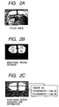
- FIG. 2A is an illustration of a static image obtained by taking a photograph through the use of a camera
- FIG. 2B is an illustration useful for explaining a monitoring range to be set in a static image
- FIG. 2C is an illustration useful for explaining a monitoring range to be set in a static image
- FIGS. 3A to 3C are illustrations useful for explaining processing for producing a difference image, and FIG. 3A shows a background image, FIG. 3B shows a present image, and FIG. 3C shows a difference image;
- FIGS. 4A to 4C are illustrations useful for explaining the binary conversion and labeling processing as image processing, and FIG. 4A shows a background image, FIG. 4B shows a present image, and FIG. 4C shows a difference image further undergoing the binary conversion and labeling processing;
- FIG. 5A is an illustration useful for explaining the processing for detecting a motion of a pixel set on the basis of two pixels continuing in time sequence;
- FIG. 5B is an illustration useful for explaining the processing for detecting a motion of a pixel set on the basis of two pixels continuing in time sequence
- FIG. 6 is an illustration useful for explaining decision processing to be conducted in a recognizing unit
- FIG. 7 is a flow chart showing decision processing according to the first embodiment
- FIG. 8 is a block diagram showing another internal configuration of the moving body detecting apparatus according to the first embodiment.
- FIG. 9 is a flow chart useful for explaining decision processing to be implemented.
- FIGS. 10A and 10B are illustrations for explaining the decision processing
- FIG. 11 is an illustration of a background image for explaining the decision processing
- FIGS. 12A and 12B are illustrations of present images for explaining the decision processing
- FIGS. 13A and 13B are illustrations of difference images for explaining the decision processing
- FIG. 14 is an illustration of a composite image for explaining the decision processing
- FIG. 15 is a block diagram showing a further configuration of the body detecting apparatus according to the first embodiment of the present invention.
- FIGS. 16A and 16B are illustrations useful for explaining a method of mounting an image pickup device
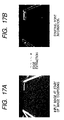
- FIGS. 17A and 17B are illustrations of an input image at image composing and an example of an image of an edge forming a starting point of a trajectory, extracted from the input image;
- FIGS. 18A to 18C are illustrations useful for explaining an input image, an example of a composite image and a trajectory extracting method
- FIG. 19 is a flow chart useful for explaining preliminary decision processing according to a third embodiment of the present invention.
- FIG. 20 is a flow chart useful for explaining decision processing according to the third embodiment.
- FIG. 21 is a block diagram showing a configuration of an image composing unit of an object detecting apparatus according to a fifth embodiment of the present invention.
- FIGS. 22A to 22C are illustrations useful for explaining an operation of an FOE (Focus Of Expansion) displacement compensating unit when an advancing direction of vehicle is changed;
- FIGS. 23A and 23B are illustrations useful for explaining an operation of an FOE displacement compensating unit when the posture of a vehicle is inclined in a roll direction;
- FIGS. 24A and 24B are illustrations useful for explaining a method of mounting an image pickup device
- FIGS. 25A to 25C are illustrations useful for explaining a method of mounting an image pickup device
- FIGS. 26A and 26B are illustrations useful for explaining a method of mounting an image pickup device
- FIGS. 27A and 27B are illustrations useful for a difference in effect between a conventional apparatus and the present invention.
- FIGS. 28A and 28B are illustrations useful for explaining a method of detecting a trajectory length
- FIG. 29 is an illustration for explaining conventional decision processing
- FIG. 1 is a block diagram showing an internal configuration of a moving body detecting apparatus according to a first embodiment of the present invention.
- the moving body detecting apparatus generally designated at reference numeral 11 , is made to function as an antitheft apparatus.
- the moving body detecting apparatus 11 is made up of a camera 13 , an area selecting unit 15 , a difference calculating unit 21 , a binary conversion/labeling unit 25 , a feature calculating unit 29 , a motion detecting unit 33 , a recognizing unit 37 , a control unit 39 , a background image memory 17 , a present image memory 19 , a difference image memory 23 , a binary conversion/labeling memory 27 , a feature calculation memory 31 , a motion detection memory 35 and a speaker 41 .
- each of the area selecting unit 15 , the difference calculating unit 21 , the binary conversion/labeling unit 25 , the feature calculating unit 29 , the motion detecting unit 33 , the recognizing unit 37 and the control unit 39 is constructed as an electronic circuit including a CPU, a ROM, a RAM and others.
- each of the background image memory 17 , the present image memory 19 , the difference image memory 23 , the binary conversion/labeling memory 27 , the feature calculation memory 31 and the motion detection memory 35 is constructed with a semiconductor memory such as a DRAM or SDRAM.
- Each of these memories can individually be constructed with a semiconductor memory, or all of these memories can also be constructed with one or plural semiconductor memories.
- the camera 13 is attached to a pillar or the like in the interior of a vehicle and is set to take a photograph continuously in time sequence in a state where break-in-possible places such as doors for a driver's seat and assistant driver's seat and their vicinities, right- and left-hand doors for a rear seat and their vicinities, a windshield and its vicinity and a rear windshield and its vicinity are set as a monitoring region or range.
- FIG. 2A shows a static image of the assistant driver's seat door and the rear seat left-hand door and their vicinities, obtained through the use of the camera 13 .
- the camera 13 has a performance to pick up 30 frames per second as monochrome static images.
- This camera 13 is realizable with a photographing device such as a CCD camera or infrared camera, or it can also be an interface device which only acquires images taken by a device separate from the moving body detecting apparatus.
- the area selecting unit 15 has a function to divide the static images from the camera 13 into an interior image of a vehicle and an exterior image thereof and stores them in the background image memory 17 and the present image memory 19 .
- This area selecting unit 15 stores the contents of a monitoring region set in order to confirm as to whether an intruder is included in static images from the camera 13 .
- monitoring regions see regions “ 201 ” and “ 203 ” in FIG. 2B
- monitoring regions for monitoring window portions in the static images are set as “allowable areas” which permit a body to exist
- monitoring regions see regions “ 202 ” and “ 204 ” in the same illustration
- monitoring door body portions in the static images are set as “unallowable areas” which do not permit a body to exist.
- the assistant driver's seat door window portion and the door body portion depend upon the positional relation in a height direction of the vehicle.
- the region “ 201 ” forming the allowable area and the region “ 202 ” forming the unallowable area have a positional relationship in the vehicle height direction (the region “ 201 ” is positioned above the region “ 202 ”).
- the assistant driver's seat door window portion and the rear seat left-hand door have a positional relationship in a longitudinal direction of the vehicle.
- the region “ 201 ” and the region “ 203 ”, forming the allowable areas has a positional relationship in a longitudinal direction (the region “ 201 ” is positioned on the left side).
- each of the above-mentioned monitoring regions is set in the form of a point set such as bit map data.
- the difference calculating unit 21 has a function to produce a difference image on the basis of a “background image” stored in the background image memory 17 and a “present image” stored in the present image memory 19 and to store the produced difference image in the difference image memory 23 .
- the difference calculating unit 21 reads out a background image (see FIG. 3A ) from the background image memory 17 and a present image (see FIG. 3B ) from the present image memory 19 to, with respect to each pixel, calculate the absolute value of a difference in luminance between both the images for producing a difference image in a state where the absolute value is used as a pixel value (see a pixel set “ 301 ” in FIG. 3C ).
- the produced difference image is put in the difference image memory 23 .
- the binary conversion/labeling unit 25 has a function to implement various image processing including processing conversion into binary image data and labeling and store the resultant image in the binary conversion/labeling memory 27 .
- the feature calculating unit 29 has a function to calculate a feature of each of pixel sets in an image stored in the binary conversion/labeling memory 27 and to store the calculation result, together with the image, in the feature calculation memory 31 .
- the motion detecting unit 33 has a function to detect a motion of each of the pixel sets on the basis of the image and each pixel set feature stored in the feature calculation memory 31 and to store the detection result, together with the feature of the each of the pixel sets, in the motion detection memory 35 . Concretely, the motion detecting unit 33 reads out two new images continuing in time sequence and the feature calculation results of image sets included in the respective images from the feature calculation memory 31 . Then, as shown in FIG. 5A , on the basis of areas of the pixel sets, the motion detecting unit 33 makes a detection as to whether or not a pixel set existing in the old image (which will be referred to hereinafter as a “previous frame”; see FIG.
- the motion detecting unit 33 calculates, as a motion vector, a movement of the position of the center of gravity of the pixel set between the previous frame and the present frame.
- the two movements of the position of the center of gravity are indicated by distances in X and Y directions.
- the center of gravity “ 514 ” in the previous frame moves to the center of gravity “ 513 ” in the present frame.
- the moving amount of the center of gravity at this time is indicated by the length of an arrow “ 517 ”.
- this also applied to a pixel set “ 512 ”.
- the information indicative of the motion vector, together with the image and the pixel set feature is stored in the motion detection memory 35 .
- the recognizing unit 37 has a function to, on the basis of the image and the feature/motion of each of the pixel sets stored in the motion detection memory 35 , recognize whether or not a moving body exists in a pixel set. Concretely, the recognizing unit 37 reads out the image and the information indicative of the feature/motion of the pixel set from the motion detection memory 35 . Subsequently, on the basis of the images and various information, the recognizing unit 37 makes a decision as to whether a pixel set satisfying all the following conditions (1) to (3) exists or not, thereby making a decision as to whether an intruder breaking from the exterior of a vehicle into the interior of the vehicle exists or not.
- Condition (1) in monitoring regions (the monitoring regions “ 201 ” and “ 203 ” in FIG. 2B ), if the following two conditions (1-1) and (1-2) are simultaneously satisfied, a decision is made that the upper half of a thief is reflected in a window portion of a vehicle.
- the first threshold corresponds to an area of a pixel set determined to detect the upper half of a thief reflected in a window portion of a vehicle and is prescribed in advance through experiments or the like.
- the second threshold corresponds to a length of vector set to detect a motion of the upper half of a thief which stops in the vicinity of the vehicle and appears in a window portion of the vehicle but set so as not to detect the upper half of a passer reflected in the window portion of the vehicle and is prescribed in advance through experiments or the like.
- Condition (2) in monitoring regions (the monitoring regions “ 202 ” and “ 204 ” in FIG. 2B ), if the following two conditions (2-1) and (2-2) are satisfied, a decision is made that an arm of a thief or the like comes from a window portion of a vehicle to a door body portion thereof.
- the third threshold corresponds to an area of a pixel set determined to detect a hand or an arm of a thief reflected in the door body portion of the vehicle and is prescribed in advance through experiments or the like.
- the width (see an arrow) of the pixel set “ 601 ” in a horizontal direction and the width (see an arrow) of the pixel set “ 603 ” in the horizontal direction do not overlap with each other as the positional relationship in the horizontal direction.
- the width (see an arrow of the pixel set “ 602 ” in the horizontal direction and the width of the pixel set “ 603 ” in the horizontal direction overlap with each other as the positional relationship in the horizontal direction.
- the speaker 41 is composed of a horn or the like and has a function to issue an alarm sound for notifying the existence of an intruder from the exterior of the vehicle to the interior thereof to a passenger such as a driver and to issue a warning sound to the body existing continuously in the monitoring region, which is set to monitor the exterior of the vehicle, for a predetermined period of time.
- the background image memory 17 is a memory for storing an image (background image) including no moving body forming an object of detection.
- This background image can be an image picked up by the camera 13 immediately after the power-on in the moving body detecting apparatus 11 , or it can also be, of the images taken by the camera 13 immediately after the power-on, an image selected periodically as an image which does not vary in time sequence. Moreover, an image taken in advance through an manipulation by a user is also acceptable.
- the present image memory 19 is for storing the present image.
- the difference image memory 23 is for storing a difference image
- the binary conversion/labeling memory 27 is for storing an image which has undergone conversion-into-binary and labeling processing.
- the feature calculation memory 31 is for storing an image which has undergone the feature calculation
- the motion detection memory 35 is for storing an image which has undergone the motion detection.
- Each of these memories is internally divided into a region (which will be referred to hereinafter as a “vehicle interior region”) for storing an interior portion including a door portion of a background image or a present image and a region (which will be referred to hereinafter as a “vehicle exterior region”) for storing an exterior portion including a window portion of a background image or a present image.
- the control unit 39 has a function to generally control the area selecting unit 15 , the difference calculating unit 21 , the binary conversion/labeling unit 25 , the feature calculating unit 29 , the motion detecting unit 33 and the recognizing unit 37 .
- the camera 13 corresponds to the image acquiring means
- area selecting unit 15 the difference calculating unit 21 , the binary conversion/labeling unit 25 , the feature calculating unit 29 , the motion detecting unit 33 , the recognizing unit 37 and the control unit 39 correspond to the decision processing means
- the speaker 41 corresponds to the notifying means and the warning means.
- step 105 an instruction is given to the area selecting unit 15 for initializing the background memory 17 and the present image memory 19 .
- the area selecting unit 15 Upon receipt of this instruction, the area selecting unit 15 initializes the background memory 17 and the present image memory 19 .
- the area selecting unit 15 makes a reply on the fact of the initialization completion to the control unit 39 , and upon receipt of this reply, the control unit 39 executes the following steps.
- each of the units (the area selecting unit 15 , and others) makes a replay on the completion of that instruction to the control unit 39 , and upon receipt of the replay, the control unit 39 executes the following steps.
- an instruction is given to the area selecting unit 15 for receiving static images from the camera 13 and storing them in the background image memory 17 .
- the area selecting unit 15 puts the following background images in the background image memory 17 . That is, when receiving the static images of the assistant driver's seat/rear seat door portion/window portion in a vehicle from the camera 13 as shown in FIG. 2A , the area selecting unit 15 encodes the pixel signals of portions corresponding to monitoring regions in the static images with a numerical value “1” (portions indicated by white color) and encodes the pixel signals of the other areas with a numerical value “0” (portions indicated by black color), as shown in FIG. 2B .
- the area selecting unit 15 calculates two-dimensional coordinates of the pixel signals encoded with the numerical value “1” and makes judgment on the position of each of the pixel signals in the vehicle interior area or the vehicle exterior area. Moreover, the area selecting unit 15 stores, as a background image, each of the pixel signals in the relevant one of the vehicle interior area and vehicle exterior area of the background image memory 17 .
- an instruction is given to the area selecting unit 15 for receiving a static image from the camera 15 to store it as the present image in the present image memory 19 .
- the area selecting unit 15 stores the following present image in the present image memory 19 . That is, when receiving a static image from the camera 13 , the area selecting unit 15 calculates two-dimensional coordinates of each of pixel signals without encoding each of the pixel signals of the static image, and makes judgment on the position of each of the pixel signals in the vehicle interior area or the vehicle exterior area to put it as the present image in the relevant one of the vehicle interior area and the vehicle exterior area of the present image memory 19 .
- each of the units when receiving various types of instructions, each of the units (the area selecting unit 15 , and others) reads out an image from the corresponding memory and stores an image in the corresponding memory according to the selection between vehicle interior area and the vehicle exterior area.
- an instruction is given to the difference calculating unit 21 for producing a difference image.
- the difference calculating unit 21 calculates the absolute value of the difference in luminance value between a background image (see FIG. 4A ) stored in the background image memory 17 and a present image (see FIG. 4B ) stored in the present image memory 19 and produces a difference image in a manner such that this value is used as a pixel value.
- the produced difference image is put in the difference image memory 23 .
- an instruction is given to the binary conversion/labeling unit 25 for conducting the image processing on the difference image.
- the binary conversion/labeling unit 25 first converts the difference image, stored in the difference image memory 23 , into binary image data according to luminance value.
- luminance value signifies a simple brightness in the case of a monochrome image and, in the case of a color image, signifies an independent luminance value of each of RGB colors or the result luminance value of the three colors.
- each of sets of pixel signals expressed by the same value, is labeled (the pixel sets “ 401 ” to “ 403 ” in FIG. 4C ).
- the image labeled for each pixel set is stored in the binary conversion/labeling memory 27 .
- an instruction for the calculation of a feature of each of the pixel sets is given to the feature calculating unit 29 .
- the feature calculating unit 29 first reads out an image from the binary conversion/labeling memory 27 and then calculates the area, center of gravity and average luminance of each of the pixel sets in the image read out therefrom. Moreover, the feature calculating unit 29 calculates the coordinates of a upper left corner and lower right corner of an external-shape rectangular configuration of the pixel set. These calculation results, together with the image, are stored in the feature calculation memory 31 .
- S 135 a decision is made as to whether or not two or more images different in time sequence are stored in the feature calculation memory 31 . If two or more images different in time sequence are not stored in the feature calculation memory 31 (S 135 : NO), the operational flow returns to S 115 to implement the steps S 115 to S 130 repeatedly. Incidentally, in a case in which the operational flow returns to S 115 to repeat S 115 to S 130 , the older one of the images stored in each of the memories other than the background image memory 17 can be deleted. On the other hand, if two or more images different in time sequence are stored in the feature calculation memory 31 (S 135 : YES), the operational flow advances to S 140 .
- an instruction is given to the motion detecting unit 33 for detecting a motion of pixel sets of the image.
- the motion detecting unit 33 first reads out two images continuing in time sequence and a feature calculation result of a pixel set included in each of the images from the feature calculation memory 31 and then, on the basis of the area of a pixel set, detects whether or not a pixel set residing in the previous frame also exists in the present frame. If a pixel set residing in common to the previous frame and the present frame is not detected (S 140 : NO), the operational flow returns to S 115 to conduct S 115 to S 130 repeatedly.
- an instruction is given to the recognizing unit 37 for implementing the recognition processing.
- the recognizing unit 37 reads out the image and the information indicative of the feature and motion of the pixel set from the motion detection memory 35 and, on the basis of these information, makes decision as to whether or not there is a pixel set satisfying all the above-mentioned conditions (1) to (3), thereby making a decision as to whether an intruder from the exterior of the vehicle to the interior thereof exists or not, with this decision result being sent as a reply to the control unit 39 .
- the operational flow from S 150 depends on the decision result in the recognizing unit 37 . That is, if the decision result indicates that an intruder from the exterior of the vehicle to the interior thereof exists, the operational flow goes to S 155 . On the other hand, if the decision result indicates that an intruder from the exterior of the vehicle to the interior thereof does not exist, the operational flow returns to S 115 to repeat S 115 to S 130 .
- a signal is sent to the speaker 41 to ring a horn for a predetermined (constant) period of time (for example, 1 minute).
- a predetermined period of time for example, 1 minute.
- the sending of a signal to the speaker 41 comes to a stop, and the operational flow returns to A 115 . This decision processing is repeatedly conducted until the power supply of the moving body detecting apparatus 11 is cut off.
- the moving body detecting apparatus 11 detects, as an intruder, only a pixel set moving from a monitoring region in the exterior of a vehicle to a monitoring region in the interior thereof and, hence, can detect only a body to be notified without detecting an object similar in feature to the body to be notified, such as a passer with respect to a thief.
- FIG. 8 is a block diagram showing another internal configuration of the moving body detecting apparatus 11 according to the first embodiment of the present invention.
- This moving body detecting apparatus 11 is mounted in a vehicle and functions as an antitheft apparatus.
- the same reference numerals represent the same or corresponding parts, and the detailed description will be omitted for brevity.
- this moving body detecting apparatus 11 is made up of a camera 13 , an image storage control unit 55 , a difference calculating unit 21 , an image composing unit 45 , an image processing unit 49 , a recognizing unit 37 , a control unit 39 , a background image memory 17 , a difference image memory 23 , an image composing memory 47 , an image processing memory 50 , and a speaker 41 .
- each of the image storage control unit 55 , the difference calculating unit 21 , the image composing unit 45 , the image processing unit 49 , the recognizing unit 37 and the control unit 39 is constructed as an electronic circuit comprising a CPU, a ROM, a RAM and others.
- the background image memory 17 , the present image memory 19 , the difference image memory 23 , the image composing memory 47 and the image processing memory 50 are constructed using a semiconductor memory such as DRAM or ADRAM.
- Each of these memories can individually be constructed with a semiconductor memory, or all of these memories can also be constructed with one or plural semiconductor memories.
- the camera 13 is attached to a central portion of a ceiling in the interior of a vehicle, the image storage control unit 55 has a function to acquire static images from the camera 13 and to store them in the background memory 17 or the present image memory 19 .
- the difference calculating unit 21 reads out images from the background image memory 17 and the present image memory to produce a difference image and put it in the difference image memory 23 .
- the image composing unit 45 reads out a difference image from the difference image memory 23 to process it with a composite image stored in the image composing memory 47 , and then stores the processed image in the image composing memory 47 .
- the image processing unit 49 reads out a composite image from the image composing memory 47 to conduct various image processing thereon and then stores the resultant image in the image processing memory 50 .
- the recognizing unit 37 recognizes whether or not a moving body exists in the image stored in the image processing memory 50 .
- the image composing memory 47 is for storing a composite image
- the image processing memory 50 is for storing an image which has undergone image processing.
- the control unit 39 has a function to generally control the image storage control unit 55 , the difference calculating unit 21 , the image composing unit 45 , the image processing unit 49 and the recognizing unit 37 .
- the camera 13 corresponds to the image acquiring means
- the image storage control unit 55 , the difference calculating unit 21 , the image composing unit 45 , the image processing unit 49 , the recognizing unit 37 and the control unit 39 correspond to the decision means
- the speaker 41 corresponds to the notifying means.
- an instruction is given to the image storage control unit 55 for initializing the present image memory 19 .
- the image storage control unit 55 initializes the present image memory 19 .
- the image storage control unit 55 makes a reply on the completion of the initialization to the control unit 39 , and in response to this reply, the control unit 39 implements the following steps. Although the description will be omitted in the following steps, as with this step, when receiving various types of instructions, each of the units (the image storage control unit 55 , and others) makes a reply on the completion of the instruction to the control unit 39 and, upon receipt of the replay, the control unit 39 executes the following steps.
- an instruction is given to the image storage control unit 55 for receiving static images from the camera 13 to store them in the present image memory 19 .
- the image storage control unit 55 receives static images from the camera 13 and stores them in the present image memory 19 .
- an instruction is given to the difference calculating unit 21 for producing a difference image.
- the difference calculating unit 21 calculates the absolute value of a difference in luminance value between a background image stored in the background image memory 17 and a static image stored in the present image memory 19 to produce a difference image in a manner such that the calculated value is used as a pixel value, with the produced difference image being stored in the difference image memory 23 .
- an instruction is given to the image composing unit 45 for initializing the image composing memory 47 .
- the image composing unit 45 Upon receipt of this instruction, the image composing unit 45 initializes the image composing memory 47 .
- an instruction is given to the image composing unit 45 for transferring the difference image to the image composing memory 47 .
- the image composing unit 45 reads out the difference image from the difference image memory 23 and stores it as a composite image in the image composing memory 47 . This composite image is identical to the difference image.
- an instruction is given so that the value of a counter to be used for the decision in S 250 , which will be mentioned later, is incremented by 1 and the image composing unit 45 carries out the image composing.
- the image composing unit 45 reads out a difference image from the difference image memory 23 by one pixel and a composite image from the image composing memory 47 by one pixel to make a comparison between the read-out pixel values. If the pixel value of the difference image is higher, the pixel value stored in the image composing memory 47 is renewed with the pixel value of the difference image. On the other hand, if the pixel value of the difference image is lower, nothing is done. This processing is conducted with respect to all the pixels thereof.
- S 250 on the basis of the value of the counter, a decision is made as to whether or not the image composing instruction to the image composing unit 45 in S 245 has been given four times. If the image composing instruction has been made four times, the value of the counter is set at zero, and the operational flow advances to S 255 . On the other hand, if the image composing instruction does not reach four times, the operational flow returns to S 230 .
- an instruction is given to the image processing unit 49 for conducting image processing.
- the image processing unit 49 reads out a composite image from the image composing memory 47 and conducts various image processing such as binary conversion and labeling to be implemented before image recognition and stores it in the image processing memory 50 .
- an instruction is given to the recognizing unit 37 for the recognition processing.
- the recognizing unit 37 reads out an image from the image processing memory 50 to make a decision as to whether or not a moving body exists in that image, and returns the decision result to the control unit 39 .
- This decision is made in consideration of a shape, area or the like of pixel set.
- the operational flow advances to different ways. If the decision result shows the existence of a moving body, the operational flow advances to S 270 . On the other hand, if it shows no existence of a moving body, the operational flow returns to S 210 .
- a signal is sent to the speaker 41 to sound a siren for a predetermined period of time (for example, 1 minute). After the elapse of the predetermined period of time, the sending of the signal to the speaker 41 comes to a stop, and the operational flow returns to S 210 . In this way, the decision processing is repeatedly conducted until the power supply to the moving body detecting apparatus 11 is cut off.
- FIG. 10A shows images 101 to 110 forming difference images produced from static images taken by the camera 13 and a background image. These difference images 101 to 110 are arranged from the left side to the right side to continue in time sequence.
- FIG. 10B is a table showing pixel values of pixels A of the images 101 to 110 .
- the images 101 to 105 successively undergo image composing processing to produce a composite image (see S 211 to S 250 in FIG. 9 ).
- This image composing is successively done in a manner such that, with respect to each pixel, a pixel value are compared with another pixel value to select the higher pixel value.
- the pixel value “98” of the image 104 is at a maximum as shown in FIG. 10B and, hence, this highest value “98” is selected.
- the image composing is made on the images 101 to 105 and the resultant composite image undergoes the image processing (see S 255 in FIG. 9 ) and the recognition processing (see S 260 in FIG. 9 ). After the completion of these processing, the image composing is newly made with respect to the images 106 to 110 .
- FIG. 11 is an illustration of a background image 1201 showing a driver's seat side door and its vicinity.
- FIG. 12A is an illustration of an n-th present image 1203 , showing a state in which an arm B breaks in the interior of a vehicle.
- FIG. 12B is an illustration of an n+4-th present image 1205 , showing a state in which the arm B enters a lower portion of the interior of the vehicle.
- FIG. 13A is an illustration of a difference image 1207 produced from the background image 1201 shown in FIG. 11 and the n-th present image 1203 shown in FIG. 12A , showing pixel sets C different in luminance value from the background image 1201 .
- FIG. 13B is an illustration of a difference image 1209 produced from the background image shown in FIG. 11 and the n+4-th present image 1205 shown in FIG. 12B , showing pixel sets D different in luminance value from the background image 1201 .
- FIG. 14 is an illustration of a composite image 1211 obtained from the n-th difference image 1207 shown in FIG. 13A , the n+1-th, n+2-th and n+3-th difference images (not shown) and the n+4-th difference image 1209 shown in FIG. 13B .
- pixel sets E have a larger area as compared with the pixel sets C shown in FIG. 13A and the pixel sets D shown in FIG. 13B .
- the moving body detecting apparatus 11 makes a decision on the existence of a moving body through the use of a composite image in which a movement trajectory of the body appears. This enables the detection of a small moving body with extremely higher accuracy than that of a conventional technique.
- a difference image is produced by calculating the absolute value of the difference in luminance value between a present image taken by the camera 13 and a background image stored in advance and a composite image is produced using that difference image, even if a moving body has a lower luminance as compared with a background image, the moving body is detectable with high accuracy.
- the image acquiring means acquires static images continuing in time sequence within the same monitoring range, and the decision processing means receives the static images from the image acquiring means to produce a composite image by successively conducting the image composing on the static images so that each pixel has the highest luminance value and, when the number of static images used for the image composing reaches a predetermined value, makes a decision as to whether or not a moving body exists in the composite image.
- the image acquiring means is realizable through the use of a photographing (imaging) device such as a camera, or it is also realizable with an interface device which merely obtains images picked up by a device separate from the moving body detecting apparatus.
- the “luminance value” may signify a simple brightness in the case of a monochrome image and, in the case of a color image, may signify an independent luminance value of each of RGB colors or the result luminance value of the three colors.
- a background image including no moving body and a static image picked up are compared one by one to detect signs of a moving body and this detection processing is conducted with respect to a plurality of static images to track the positions of the signs of a moving body in the static images for making a decision as to whether or not it is a moving body. Therefore, in a case in which a moving body is relatively small in the entire static image, the conventional technique can result in misjudgment.
- the decision processing means prior to the detection of a body, the decision processing means conducts the image composing on the static images so that each pixel has the highest luminance value, and detects a moving body using one composite image.
- the moving body detecting apparatus can detect, with extremely high accuracy, a moving body which can fall into a background like a small moving body.
- a moving body when a composite image is produced by conflating a plurality of static images, a moving body can fall into a background.
- a monochrome image when the luminance value of the background is high and the luminance value of the moving body is low, even if the moving body exists at a given pixel, the luminance value of the background achieves domination over the luminance value of the moving body when the moving body moves and, hence, the moving body can disappear as a result.
- the decision processing means receives static images from the image acquiring means and calculates an absolute value of the difference in luminance value between each of a plurality of static images from the image acquiring means and the background image stored in advance for each pixel to produce a difference image, and through the use of the difference images, a composite image is produced by the successive image composing so that each pixel has the highest absolute value, and when the number of difference images used for the image composing reaches a predetermined value, a decision is made as to whether or not a body moving exists in the composite image.
- the “background image” signifies an image in which a moving body is absent.
- This difference image is produced by calculating the absolute value of the difference in luminance value between a static image received from the image acquiring means and a background image stored in advance and, hence, the difference image does not represent the comparison result in magnitude of luminance between both the images but signifying the comparison result in the difference of luminance therebetween. Therefore, this eliminates the above-mentioned problem of a moving body being broken because the background luminance value is high, thereby enabling high-accuracy detection of a moving body.
- the decision processing means can carry out the image composing using all the static images from the image acquiring means, it is also appropriate that, when receiving static images from the image acquiring means, the decision processing means makes a decision as to whether to select the static images and continues the decision processing only in the case of the selection thereof.
- the selecting manner for example, it can be considered to use a method of regularly and selectively thinning static images or a method of making the selection only when there is a difference between the static images continuing in time sequence.
- the decision processing means can achieve an efficient decision without depending on the static image acquiring rate per unit time in the image acquiring means.
- the concrete decision as to whether or not a moving body exists in a composite image can be as follows. That is, a composite image is converted into binary image data and labeled and, on the basis of an area and shape of the resultant pixel set, a decision is made on the existence of a moving body.
- the “on the basis of an area and shape of a pixel set” signifies that, for example, noting the areas of the pixel sets, pixel sets having an area exceeding a predetermined area are selected.
- a moving direction is estimated on the basis of the direction in which the selected pixel set is elongated and, finally, a decision is made as to whether or not it is a moving body.
- an area of a pixel set is calculated through the use of a counter.
- the notifying means can be made to transmit the fact of the decision indicating the existence of a moving body to an internal separate apparatus, it is also appropriate that notifying means is provided which is for notifying the existence of a moving body to a user, and the decision means is made to give an instruction to the notifying means for notifying the existence of the moving body to the user.
- the moving body detecting apparatus is used as an antitheft apparatus. Since the consumable power is limited during the vehicle storage, difficulty can be experienced in locating a sufficient light source(s), thus making it difficult to provide a static image having a sufficient contrast. Even in such a situation, the moving body detecting apparatus according to the present invention can achieve the detection with high accuracy, thus providing a high utility value.
- the decision processing means of the moving body detecting apparatus is also realizable in a manner such that a program functioning as the decision processing means is used and implemented in a computer incorporated into the moving body detecting apparatus.
- This program is recorded on a computer-readable recording medium such as a flexible disk, magnetic optical disk, CD-ROM, hard disk, ROM or RAM, and is loaded into the computer and activated when needed. It is also possible to perform the loading and activation through a network.
- FIG. 15 is a block diagram showing the entire configuration of a vehicle-mounted body detecting apparatus for detecting an body existing on a load at the rear of a vehicle or a mark drawn on a road on the basis of a plurality of input images (monochrome images) picked up continuously toward the rear of the vehicle.
- a body detecting apparatus 11 a is made up of an image pickup device (camera) 13 for photographing the rear of a vehicle, an image composing unit 45 for carrying out the image composing processing on a plurality of input images picked up continuously by the image pickup device 13 , a composite image processing unit 104 functioning as composite image processing means and comprises a starting-point extracting unit 131 for extracting, as a starting point, a feature point (which is equally referred to as an image pickup point) of a body from the input image at the start of the image composing processing and a displacement data producing unit 121 for obtaining displacement data (in this case, the coordinates of a starting point and end point of a trajectory, the length of the trajectory) indicative of a displacement of a static body appearing in the input image on the basis of the starting point extracted by the starting-point extracting unit 131 and a composite image produced by the image composing unit 45 , a movement distance calculating unit 105 for detecting the distance of the movement of the vehicle while the image pickup device
- the image pickup device 13 is composed of a CCD camera or the like, and is set so that, as shown in FIG. 16A , its optical axis is directed obliquely and downwardly and, as shown in FIG. 16B , an infinity point (FOE) in an image picked up is placed at a central portion of a frame width in a horizontal direction and at an upper portion outside the frame in a vertical direction.
- FOE infinity point
- the image composing unit 45 is composed of a composite image memory 113 serving as a composite image storing means to store a composite image by one frame and a comparator 111 serving as a pixel value updating means to, with respect to each pixel existing at the same position in a frame, make a comparison in magnitude of the pixel value between a composite image stored in the composite image memory 113 and a monochrome image (which will be referred to hereinafter as an “inafter as an “inafter as an “input image”) from the image pickup device 13 for updating the pixel value of the composite image when the pixel value of the input image is higher.
- the comparator 111 is made to directly store the input image at the start of image composing in the composite image memory 113 .
- the starting-point extracting unit 131 constituting the composite image processing unit 104 is composed of an edge extracting filter 133 for extracting an edge of an input image at the start of the image composing and a starting-point information database 135 for storing, as starting-point information, the coordinates of starting points in a frame in a state where pixels corresponding to the edge (image pickup point group) extracted by the edge extracting filter 133 are taken as the starting points.
- the displacement data producing unit 121 is composed of a notice line setting unit 127 for setting, as a notice line, each of lines making connections between the starting points stored in the starting-point information database 135 and the FOE in an input image, an edge extracting filter 123 for, on the basis of a composite image stored in the composite image memory 113 after the image composing, extracting pixels corresponding to an edge of the composite image and existing on the notice lines as end points, and a trajectory length calculating unit 125 for combining the coordinates of the starting point and the end point existing on the same notice line to obtain, as a trajectory length, the distance between the starting point and the end point after the combination for producing displacement data including the coordinates and the trajectory length.
- a notice line setting unit 127 for setting, as a notice line, each of lines making connections between the starting points stored in the starting-point information database 135 and the FOE in an input image
- an edge extracting filter 123 for, on the basis of a composite image stored in the composite image memory 113 after the image composing, extracting
- FIG. 17A is an illustration of one example of an image to be taken by the image pickup device 13 in a case in which a vehicle is parked in a parking zone in a backward-looking posture, where there appear partition lines of a parking space and a tire stopper made using a concrete block.
- the edge extracting filter 133 extracts profiles of the partition lines and a profile of the tire stopper which have a higher contrast with respect to other portions, and the coordinates of the pixels corresponding to these profiles are stored as starting-point information in the starting-point information database 135 .
- the image composing unit 45 sequentially conflates a plurality of input images (see FIG. 18A ) picked up by the image pickup device 13 in accordance with the backward movement of the vehicle to provide a composite image as shown in FIG. 18B .
- a trajectory of an image pickup point having a high gradient appears in that composite image, and the trajectory is along a notice line directed at the FOE.
- FIG. 18C is a distribution map of pixel values of pixels on the notice line L shown in FIG. 18B . In this case, let it be assumed that two starting points A and B exist on the notice line L.
- the edge extracting filter 123 extracts an edge (that is, a spot at which the pixel value decreases rapidly) along the notice line L from each of the starting points A and B, thereby extracting spots C and D as end points of the trajectory on the notice line L.
- the trajectory length calculating unit 125 obtains the trajectory length TA between the starting point A and the end point C and the trajectory length TB between the starting point B and the end point D
- the displacement data producing unit 121 produces displacement data comprising the coordinates of each of the starting point A and the end point C and the trajectory length TA and displacement data comprising the coordinates of each of the starting point B and the end point D and the trajectory length TB.
- the displacement data producing unit 121 conducts the same processing with respect to all the notice lines including starting points stored in the starting-point information database 135 , with all the displacement data thus obtained being supplied to the position calculating unit 106 .
- an edge of a composite image is extracted along a notice line to extract an end point of a trajectory
- a region including a starting point stored in the starting-point information database 135 and having a pixel value larger than a threshold set in advance is extracted from a distribution map (see FIG. 18C ) of pixel values along a notice line and the length of the extracted region is obtained as a trajectory length.
- the position calculating unit 106 calculates a position (relative distance, bearing, height from a road surface, and others) of a static body appearing in an input image on the basis of the displacement data (coordinates of starting points and end points of loci, trajectory lengths) thus obtained, the movement data on a vehicle (that is, the image pickup device 13 ) and the mounting data (focal length, mounting height, mounting angle) on the image pickup device 13 set in advance through the use of a well-known method (for example, see Japanese Patent Laid-Open Nos. HEI 7-78252 and 2001-187553) based on a tigonometrical survey.
- a well-known method for example, see Japanese Patent Laid-Open Nos. HEI 7-78252 and 2001-187553
- the body detecting apparatus 11 a conducts the image composing on input images taken continuously and obtains displacement data indicative of a displacement of a static body in a frame in the input images on the basis of a trajectory of an image pickup point appearing in the resultant composite image and a starting point extracted from the input image at the start of the image composing.
- this body detecting apparatus 11 a it is possible to associate the same image pickup points shown in different images in a less calculation quantity without employing the pattern matching requiring a fabulous processing quantity and to obtain displacement data indicative of the displacement with high accuracy. As a result, this enables the detection of the position of a static body appearing in input images for a short time, and achieves high-reliability detection.
- a displacement data extracting method of obtaining a plurality of input images continuously picked up and acquiring, as each of representative pixel values, a maximum value of pixels existing at the same positions in frames of the input images to produce a composite image comprising the representative pixel values and extracting displacement data indicative of a displacement of a photographed body in the frames on the basis of a trajectory of an image pickup point appearing in the composite image.
- the displacement data it is also possible to use the coordinates of a starting point and end point of a trajectory of an image pickup point or to use a length of the trajectory.
- a body detecting apparatus comprising image composing means for obtaining a plurality of input images continuously picked up and acquiring, as each of representative pixel values, a maximum value of pixels existing at the same positions in frames of the input images to produce a composite image comprising the representative pixel values and composite image processing means for extracting displacement data indicative of a displacement of a photographed body in the frames on the basis of a trajectory of an image pickup point appearing in the composite image.
- this body detecting apparatus realizes the above-mentioned displacement data extracting method, and provides the same effects.
- the image pickup device can be fixed in place or can also be mounted on a mobile body (moving body).
- a movement quantity of a mobile body can be obtained on the basis of the displacement data extracted by the composite image processing means.
- a position of a static body can be obtained on the basis of distance data indicative of a movement distance of the mobile body in the middle of the photograph of the input images used for the production of the composite image, the displacement data extracted by the composite image processing means and the mounting position data indicative of the mounting position of the image pickup device.
- an image pickup point on a static body photographed as an input image forms a trajectory along a notice line in a composite image.
- the composite image processing means extracts, as a starting point (see “S” in FIG. 28A ), an edge of a body taken in an input image at the start of image composing in the image composing means and extracts, as an end point (see “E” in FIG. 28B ), an edge of a trajectory shown in a composite image produced by the image composing means, and a line passing through a motion infinity point in an input image is set as a notice line (see “L” in FIGS. 28A and 28B ) and the displacement data is obtained on the basis of a starting point and an end point existing on the same notice line.
- the processing quantity in the image composing means is considerably reducible.
- the image composing means controls the timing of the completion of image composing according to starting point to prevent the loci different in starting point from each other from being connected to each other.
- the image composing means includes composite image storing means, and pixel updating means sequentially compares a pixel value of an input image obtained from the image pickup device and a pixel value of a composite image stored in the composite image storing means and, if the pixel value of the input image is larger than the pixel value of the composite image, updates the storage contents in the composite image storing means with the pixel value of the input image.
- the mounting height of the image pickup device from a road surface varies due to a variation of the posture of the vehicle or sinking of the vehicle body. Therefore, in a case in which there is a need to calculate the height of an image pickup point from a read surface on the basis of displacement data, it is preferable to make a correction for offsetting the variation of the mounting height.
- the image pickup device is placed so that the motion infinity point is positioned at a circumferential edge of a frame.
- the image pickup device can be placed so that the motion infinity point is positioned in the exterior of the frame. Moreover, when the image pickup device is placed so that the optical axis coincides with a vertical direction (that is, the motion infinity point is positioned at the infinity), it is possible to exhibit the maximum distance resolution of an input image.
- the above-described moving body detecting apparatus acts as an antitheft apparatus to be mounted in a vehicle, it is also applicable to a break-in-prevention apparatus to be installed at a place, such as an entrance or window of a building, where it is required to prevent an intruder from breaking in. Moreover, it is also applicable to an antitheft apparatus to be installed at a spot such as a store or art museum requiring the prevention of approach of a thief around an article or picture.
- the camera 13 is set to provide static images of an interior of an art museum and the interior of an exhibition room is set as an allowable area while an exhibit, such as a picture in the room, and its vicinities is set as an unallowable area.
- warning in a case in which a moving body around a vehicle exists continuously for a predetermined period of time, warning can be made to that moving body.
- the motion detecting unit 33 detects that a pixel set residing in common to the previous frame and the present frame is in an allowable area, if the pixel set exists continuously in the allowable area for a predetermined period of time (for example, several seconds), a warning is given to that moving body, such as 1) a warning being made with a voice from the speaker 41 , 2) an alarm lamp being lighted, and 3) a buzzer being sounded. This can previously prevent a moving body around the vehicle from breaking in the vehicle.
- the recognizing unit 37 judges that an intruder from the exterior of a vehicle to the interior thereof exists, information to the effect of the existence of the intruder can be sent through a transmitting means to an external different apparatus such as a portable telephone pertaining to the owner of the vehicle or a telephone in a house of the owner of the vehicle. This achieves quick notification on the existence of an intruder from the exterior of the vehicle to the interior thereof to the owner of the vehicle.
- the background image memory 17 is initialized at the start of the decision processing and background images are stored in the initialized background image memory 17 , it is also appropriate that, for example, the background images are updated when the decision in the recognizing unit 37 indicating no existence of an intruder is made a predetermined number of times.
- the monitoring regions “ 201 ” and “ 203 ” for monitoring window portions in static images are set as an “allowable area” while the monitoring regions “ 202 ” and “ 204 ” for monitoring door body portions in the static images are set as an “unallowable area” as shown in FIG. 2B
- the present invention is not limited to this but it is also appropriate that, for example, the monitoring regions “ 201 ” and “ 203 ” are set as the unallowable area while the monitoring regions “ 202 ” and “ 204 ” are set as the allowable area, thus detecting a body such as a handbag or purse brought from the interior of the vehicle to the exterior thereof.
- the unallowable areas are positioned above the allowable areas.
- the condition (2) is altered to the following condition (2′). That is, when the following condition is satisfied, a decision is made that a body such as a handbag or purse is moved from a door body portion of a vehicle to a window portion thereof. the area of a monitoring region>a fourth threshold (2′-1) the direction of a motion vector is upward (2′-2)
- the fourth threshold corresponds to an area of a pixel set determined to detect a body such as a handbag or purse reflected in the door body portion of the vehicle and is prescribed in advance through experiments or the like. If there is a pixel set satisfying all the above-mentioned conditions (1), (2′) and (3), a decision is made that this pixel set represents a body such as a handbag or purse. This enables the detection of a body such as a handbag or purse taken out from the interior of a vehicle to the exterior thereof.
- a static image is divided into a vehicle interior image and a vehicle exterior image, and is stored in the background image memory 17 or the present image memory 19
- the present invention is not limited to this, but it is also appropriate that a monitoring region extracted from a static image is divided into a vehicle interior image and a vehicle exterior image, and is stored in the background image memory 17 or the present image memory 19 .
- the memory size of the storage unit is reducible as compared with the case of storing a static image.
- the present invention is not limited to this, but it is also appropriate that the encoding is made with a different numerical value for each monitoring region.
- the encoding (multi-valued conversion) is made with the numerical value “1” for the monitoring region “ 201 ”, the encoding is made with the numerical value “2” for the monitoring region “ 202 ”, the encoding is made with the numerical value “3” for the monitoring region “ 203 ”, the encoding is made with the numerical value “4” for the monitoring region “ 204 ”, and the encoding is made with the numerical value “0” for the non-monitoring region.
- each of the monitoring regions is set in the form of a point set such as bit map data
- the present invention is not limited to this, but it is also appropriate that the monitoring regions are prescribed using the boundary (border) lines of their outer circumferences. These boundary lines can be expressed in the form of a point set or using a function.
- the data quantity for setting the monitoring regions becomes only data for setting the boundary lines and, hence, the data quantity is reducible as compared with the above-mentioned case of setting the monitoring regions in the form of a point set, thus reducing the memory size of the storage unit for storing the set data.
- the monitoring regions can also be set as circumscribed rectangles.
- the monitoring regions are set at both end portions of a diagonal line of the rectangle, the data quantity is further reducible.
- the monitoring region “ 203 ” is set in the form of a rectangle in which the coordinate 1 ( 200 , 20 ) and the coordinate 2 ( 400 , 60 ) constitute both ends of a diagonal line. Each side of the rectangle forms a boundary line of a monitoring region.
- FIGS. 8 , 19 and 20 a description will be given hereinbelow of a moving body detecting apparatus 401 according to a third embodiment of the present invention. The description will basically be made about the differences from the above-described moving body detecting apparatus 11 for brevity.
- a control unit 437 is made to implement preliminary decision processing and decision processing, and the preliminary decision processing starts in response to the power-on of the moving body detecting apparatus 401 , and the decision processing starts in the middle of the preliminary decision processing.
- the preliminary decision processing will first be described with reference to a flow chart of FIG. 19 .
- an instruction is given to the image storage control unit 55 for initializing the present image memory 19 .
- the image storage control unit 55 initializes the present image memory 19 .
- the image storage control unit 55 makes a reply on the fact of the initialization completion to the control unit 437 , and upon receipt of this reply, the control unit 437 executes the following steps.
- each of the units (the image storage control unit 55 , and others) makes a replay on the completion of that instruction to the control unit 437 , and upon receipt of the replay, the control unit 437 executes the following steps.
- an instruction is given to the image storage control unit 55 for receiving static images from the camera 13 to store them in the present image memory 19 .
- the image storage control unit 55 acquires static images from the camera 13 and puts them in the present image memory 19 .
- an instruction is given to the difference calculating unit 21 .
- the difference calculating unit 21 calculates, for each pixel, the absolute value of the difference in luminance value between a background image stored in the background memory 17 and a static image stored in the present image memory 19 to produce a difference image in a manner such that the calculated value is set as a pixel value, with the produced difference image being stored in the difference image memory 23 .
- an instruction is given to the difference calculating unit 21 for making a decision as to whether a predetermined quantity of pixel set exists in the difference image.
- the difference calculating unit 21 makes a decision as to whether, in the calculated difference image, a pixel set having a predetermined quantity exists at a window portion.
- the “predetermined quantity” signifies a magnitude or size of a pixel set appearing when a person stands in the vicinity of a door. If there is a pixel set having the predetermined quantity, the operational flow advances to S 330 . Otherwise, the operational flow proceeds to S 340 .
- the operational flow from S 330 depends on whether or not the decision processing, which will be mentioned later, is in execution. If the decision processing is in execution, the operational flow returns to S 310 . Otherwise, the operational flow proceeds to S 335 . In S 335 , the decision processing is started and, after the starting, the operational flow returns to S 310 .
- the operational flow from S 340 depends on whether or not the decision processing is in execution. If the decision processing is in execution, the operational flow proceeds to S 345 . Otherwise, the operational flow returns to S 310 . In S 345 , the decision processing is forcibly stopped, and then the operational flow returns to S 310 .
- an instruction is given to the image composing unit 45 for the initialization of the image composing memory 47 .
- the image composing unit 45 Upon receipt of this instruction, the image composing unit 45 initializes the image composing memory 47 .
- an instruction is given to the image composing unit 45 for transferring a difference image to the image composing memory 47 .
- image composing unit 45 reads out a difference image from the difference image memory 23 and stores it as a composite image in the image composing memory 47 . This composite image is identical to the difference image.
- an instruction is given to the difference calculating unit 21 for checking whether or not a newer difference image than the difference image transferred in S 415 exists in the difference image memory 23 .
- the difference calculating unit 21 makes a decision as to whether or not a newer difference image exists in the difference image memory 23 , and makes a reply on that decision result to the control unit 437 . If the newer difference image exists in the difference image memory 23 , the operational flow advances to S 425 . Otherwise, the operation falls into the stand-by condition until a new difference image is stored in the difference image memory 23 .
- the value of a counter to be used for the decision in S 430 is incremented by one, and an instruction is given to the image composing unit 45 for the image composing.
- the image composing unit 45 reads out, pixel by pixel, a difference image from the difference image memory 23 and a composite image from the image composing memory 47 to make a comparison between the pixel values. If the pixel value of the difference image is higher, the pixel value of the pixel stored in the image composing memory 47 and compared is updated with the pixel value of the difference image. On the other hand, if the pixel value of the difference image is lower, nothing is done. This processing is conducted with respect to all the pixels.
- S 430 on the basis of the counter value, a decision is made as to whether or not the image composing instruction to the image composing unit 45 in S 425 has been given four times. If the image composing instruction has been made four times, the value of the counter is set at zero, and the operational flow advances to S 435 . On the other hand, if the image composing instruction does not reach four times, the operational flow returns to S 420 .
- an instruction is given to the image processing unit 49 for the image processing.
- the image processing unit 49 reads out a composite image from the image composing memory 47 and conducts various image processing such as binary conversion and labeling to be implemented before image recognition and stores it in the image processing memory 50 .
- an instruction is given to the recognizing unit 37 for the recognition processing.
- the recognizing unit 37 reads out an image from the image processing memory 50 to make a decision as to whether or not a moving body exists in that image, and returns the decision result to the control unit 437 .
- This decision is made in consideration of a shape, area or the like of pixel set.
- the operational flow from S 445 depends on the decision result in the recognizing unit 37 in S 440 . If the decision result in S 440 shows the existence of a moving body, the operational flow advances to S 450 . On the other hand, if the decision result in the S 440 shows no existence of a moving body, the operational flow advances to S 455 .
- a signal is sent to the speaker 41 to sound a siren for a predetermined period of time (for example, 1 minute). After the elapse of the predetermined period of time, the sending of the signal to the speaker 41 comes to a stop, and the operational flow returns to S 455 .
- an instruction is given to the difference calculating unit 21 for checking whether or not a newer difference image than the difference image in S 420 exists in the difference image memory 23 .
- the difference calculating unit 21 makes a decision as to whether or not a newer difference image exists in the difference image memory 23 and returns the decision result to the control unit 437 . If the newer difference image exists in the difference image memory 23 , the operational flow returns to S 410 . Otherwise, the operation falls into the stand-by condition until a new difference image is stored in the difference image memory 23 .
- This decision processing is repeatedly conducted until the power supply of the moving body detecting apparatus 11 is cut off or until it is stopped by the preliminary decision processing.
- control unit 437 the image storage control unit 55 and the difference calculating unit 21 correspond to preliminary decision processing means
- control unit 437 the difference calculating unit 21 , the image composing unit 45 , the image processing unit 49 and the recognizing unit 37 correspond to the decision means.
- the preliminary decision processing is provided to compare a background image stored in advance and a static image obtained by the image acquiring means with each other with respect to a predetermined region to make a preliminary decision as to whether or not they shows a difference exceeding a predetermined quantity and the decision means conducts the decision processing only while the preliminary decision result in the preliminary decision processing means indicates a difference exceeding the predetermined quantity.
- the “predetermined region” signifies a specified area in an image determined in advance
- the “difference exceeding the predetermined quantity” signifies a quantitatively calculable physical quantity, for example, the number of pixels having different luminance values (disagreement in luminance) or the discrete degrees of these pixels.
- the image acquiring means is set so that a door portion and a window portion of a door are photographed to obtain static images and the window portion in the static image is set as a predetermined region for which the preliminary decision means makes a preliminary decision.
- the preliminary decision processing means compares the window portion in a background image stored in advance and the window portion in a static image acquired by the image acquiring means to continuously make a decision as to whether or not a difference therebetween, which indicates the possibility of existence of a person, exists in both the images.
- the decision means implements a series of decision processing only while the decision in the preliminary decision processing means shows the “difference indicating the possibility of existence of a person”.
- the decision processing means implements a series of decision processing. Accordingly, the decision processing is conducted only when needed, if the power per unit time to be used for the decision processing in the decision processing means is larger than the power per unit time to be used for the preliminary decision processing in the preliminary decision processing means, the power consumption per unit time is reducible as compared with the case in which the decision processing is carried out at all times.
- a difference image for only a required region for example, a difference image for only a window portion, is produced in the preliminary decision processing. This can further enable the reduction of power consumption. However, there is a need to produce a difference image in the decision processing on another occasion.
- a composite image is produced from five static images, no limitation is imposed on the number of static images. It can be determined on the basis of information such as a possible frame rate of the camera 13 or an estimated movement speed of a moving body forming an object of detection.
- a selecting means is provided to selectively use the static images taken by the camera 13 .
- the selecting manner it can be considered to use a method of regularly and selectively thinning static images or a method of dynamically changing the number of static images to be used on the basis of the processing load. This enables the realization of the present invention even through the use of a processing unit such as a CPU having a low processing ability per unit time.
- each of parts such as the control unit 39 , 437 , the image storage control unit 55 , the difference calculating unit 21 and others is an electronic circuit constructed separately using a CPU, a ROM, a RAM and other components, it is also appropriate to realize all the parts through the use of one CPU and a program to be executed by the CPU.
- a description will be given hereinbelow of a body detecting apparatus according to a fifth embodiment of the present invention.
- the difference of this body detecting apparatus according to the fifth embodiment from the body detecting apparatus according to the first embodiment is only a portion of the configuration of the image composing unit, and the description will principally be given about the portion different therefrom.
- an image composing unit 45 a is provided with an FOE displacement compensating unit 115 functioning as a compensating means to compensate for a displacement (positional deviation) of the FOE (Focus Of Expansion) occurring among the input image from the image pickup device 13 on the basis of detecting signals from a steering sensor 141 for detecting a variation of the advancing (traveling) direction of a vehicle, an acceleration sensor 143 for detecting a speed variation of the vehicle in the advancing direction and a yaw rate sensor 145 for detecting a variation of the angular velocity of the vehicle in its turning direction.
- the input images undergoing the displacement compensation in the FOE displacement compensating unit 115 are supplied to the comparator 111 .
- the FOE of the input image (which will hereinafter be referred to as a “present FOE”) is horizontally displaced or shifted along a horizontal plane with respect to the FOE of the input image at the start of the image composing (which will hereinafter be referred to as an “initial FOE”) as shown in FIG. 22B .
- the FOE displacement compensating unit 115 detects this displacement on the basis of a detection signal from the steering sensor 141 and, as shown in FIG. 22C , horizontally shifts the association (correspondence) in pixel between the composite image and the input image to offset the FOE displacement so that the present FOE coincides with the initial FOE.
- the present FOE is displaced vertically with respect to the initial FOE.
- the FOE displacement compensating unit 115 detects this displacement on the basis of a detection signal from the acceleration sensor 143 and vertically shifts the association in pixel between the composite image and the input signal to compensate for the FOE displacement so that the present FOE agrees with the initial FOE.
- the input image is shifted in a turning direction with respect to the input image at the start of the image composing.
- the FOE displacement compensating unit 115 detects this displacement on the basis of a detection signal from the yaw rate sensor 145 and, as shown in FIG. 23B , shifts the association in pixel between the composite image and the input image in vertical directions, horizontal directions and turning directions so that the present FOE agrees with the initial FOE and the horizontal and vertical directions in the frames agree with each other.
- the trajectory of an image pickup point becomes a straight line(s) along a notice line(s) as shown in FIG. 22C or 23 B without becoming a curve as shown in FIG. 22B and, hence, a composite image can be processed to extract displacement data as in a case in which the vehicle is going straight. That is, the position of a static body appearing in an input image can easily be obtained stably and accurately irrespective of the variation in behavior and posture of the vehicle.
- the image composing means includes compensating means to, if a displacement of the infinity point occurs, compensate for the displacement by varying the association between the pixel of the input image obtained from the image pickup device and the pixel of the composite image stored in the composite image storing means.
- the compensating means can detect a variation of the advancing direction of a mobile body as the behavior of the mobile body, and in particular, if the mobile body is a vehicle, the compensating means can detect a variation of the posture of the vehicle.
- the posture of the vehicle it is possible to detect at least one of the inclination of the vehicle in a longitudinal direction due to an acceleration in the advancing direction of the vehicle and the inclination in transverse direction due to an angular velocity in a turning direction of the vehicle.
- the image pickup device 13 is set such that the FOE is placed at a central portion of a frame width in a horizontal direction and at an upper portion outside the frame in a vertical direction, it is also appropriate that the image pickup device 13 is set such that an optical axis P agrees with the direction of the FOE as shown in FIG. 24A and the FOE is positioned at a central portion of a frame as shown in FIG. 24B .
- the image pickup device 13 is placed such that, at least, an upper end of the image pickup range of the image pickup device 13 coincides with the FOE direction as shown in FIG. 25A and the FOE is positioned at an upper edge portion of the frame as shown in FIGS. 25B and 25C .
- the image pickup device 13 can also be installed so that the optical axis agrees with a vertical direction as shown in FIG. 26A and the notice lines become in parallel with each other (the FOE is positioned at the infinity above the frame) as shown in FIG. 26B .
- the image composing unit 45 , 45 a is made to produce a composite image using all pixels, it is also appropriate that a composite image is produced using only pixels on notice lines set by the notice line setting unit 127 . In this case, the processing quantity in the image composing unit 45 , 45 a is considerably reducible.
- the comparator 111 controls the timing of the completion of image composing according to starting point to prevent the loci different in starting point from each other from being connected to each other.
- the position calculating unit 106 uses the mounting data set in advance, it is also appropriate that, in a case in which a vehicle body falls into a sinking condition due to the loading of a heavy thing, the vehicle body sinking is detected to correct the mounting height forming one of mounting data.
- the image pickup device 13 is mounted on a vehicle and the detection of the position of a static body is made on the basis of a composite image made from input images continuously picked up by the image pickup device 13 , it is also appropriate that the image pickup device 13 is fixed in place and the position or movement quantity of a moving body is obtained on the basis of displacement data obtained from a composite image of input images continuously taken by the image pickup device 13 .
Landscapes
- Engineering & Computer Science (AREA)
- Mechanical Engineering (AREA)
- Multimedia (AREA)
- Computer Vision & Pattern Recognition (AREA)
- Physics & Mathematics (AREA)
- General Physics & Mathematics (AREA)
- Theoretical Computer Science (AREA)
- Image Analysis (AREA)
- Burglar Alarm Systems (AREA)
Abstract
Description
the area of a pixel set>a first threshold (1-1)
the length of a motion vector<a second threshold (1-2)
the area of a pixel set>a third threshold (2-1)
the direction of a motion vector is downward (2-2)
the area of a monitoring region>a fourth threshold (2′-1)
the direction of a motion vector is upward (2′-2)
Claims (64)
Applications Claiming Priority (6)
| Application Number | Priority Date | Filing Date | Title |
|---|---|---|---|
| JP2002-273388 | 2002-09-19 | ||
| JP2002273388A JP3956817B2 (en) | 2002-09-19 | 2002-09-19 | Displacement data extraction method and object detection apparatus |
| JP2002-366934 | 2002-12-18 | ||
| JP2002366934A JP3956843B2 (en) | 2002-12-18 | 2002-12-18 | Moving object detection device and program |
| JP2003-63714 | 2003-03-10 | ||
| JP2003063714A JP2004274479A (en) | 2003-03-10 | 2003-03-10 | Moving object detecting apparatus and program thereof |
Publications (2)
| Publication Number | Publication Date |
|---|---|
| US20040057600A1 US20040057600A1 (en) | 2004-03-25 |
| US7433494B2 true US7433494B2 (en) | 2008-10-07 |
Family
ID=31998773
Family Applications (1)
| Application Number | Title | Priority Date | Filing Date |
|---|---|---|---|
| US10/662,401 Expired - Fee Related US7433494B2 (en) | 2002-09-19 | 2003-09-16 | Moving body detecting apparatus |
Country Status (1)
| Country | Link |
|---|---|
| US (1) | US7433494B2 (en) |
Cited By (8)
| Publication number | Priority date | Publication date | Assignee | Title |
|---|---|---|---|---|
| US20060221185A1 (en) * | 2005-02-28 | 2006-10-05 | Sony Corporation | Information processing system, information processing apparatus and information processing method, program, and recording medium |
| US20080044058A1 (en) * | 2006-08-17 | 2008-02-21 | Inventec Corporation | System and method for setting image-monitoring regions |
| US20090103815A1 (en) * | 2007-10-22 | 2009-04-23 | Denso Corporation | Body position detecting apparatus |
| US7826640B1 (en) * | 2004-02-19 | 2010-11-02 | State University New York | Hierarchical static shadow detection method |
| US20110001884A1 (en) * | 2008-03-28 | 2011-01-06 | Nec Corporation | Image processing system, image processing method, and recording medium storing image processing program |
| CN103448670A (en) * | 2012-05-31 | 2013-12-18 | 天翔系统整合股份有限公司 | Vehicle monitoring system |
| US20160063310A1 (en) * | 2013-03-28 | 2016-03-03 | Nec Corporation | Bird detection device, bird detection system, bird detection method, and program |
| US20180137352A1 (en) * | 2016-11-16 | 2018-05-17 | Fuji Xerox Co., Ltd. | Image processing apparatus and non-transitory computer readable medium |
Families Citing this family (43)
| Publication number | Priority date | Publication date | Assignee | Title |
|---|---|---|---|---|
| GB2408879A (en) | 2003-12-03 | 2005-06-08 | Safehouse Internat Inc | Storing data recorded over a period of time |
| US7428314B2 (en) * | 2003-12-03 | 2008-09-23 | Safehouse International Inc. | Monitoring an environment |
| JP3898709B2 (en) * | 2004-05-19 | 2007-03-28 | 本田技研工業株式会社 | Vehicle lane marking recognition device |
| JP4437714B2 (en) * | 2004-07-15 | 2010-03-24 | 三菱電機株式会社 | Lane recognition image processing device |
| JP4506409B2 (en) * | 2004-10-27 | 2010-07-21 | 株式会社デンソー | Region dividing method and apparatus, image recognition processing apparatus, program, and recording medium |
| DE502006003568D1 (en) * | 2005-11-22 | 2009-06-04 | Frank H Schaefer | DEVICE FOR TESTING TIRE PROFILE DEPTH AND TYPE, SPEED AND BODY FREQUENCY ON VEHICLES DURING THE RIDE |
| JP4696991B2 (en) * | 2006-03-22 | 2011-06-08 | 日産自動車株式会社 | Motion detection method and motion detection apparatus |
| EP1927957A1 (en) * | 2006-11-29 | 2008-06-04 | Sick Ag | Method and apparatus for surveillance of an area |
| DE102009007842A1 (en) * | 2009-02-06 | 2010-08-12 | Adc Automotive Distance Control Systems Gmbh | Method and device for operating a video-based driver assistance system in a vehicle |
| JP5493709B2 (en) * | 2009-03-13 | 2014-05-14 | 株式会社リコー | Video editing device |
| JP5340213B2 (en) * | 2010-03-30 | 2013-11-13 | 富士フイルム株式会社 | Image display system |
| JP5460635B2 (en) * | 2011-03-31 | 2014-04-02 | 本田技研工業株式会社 | Image processing determination device |
| US9233659B2 (en) | 2011-04-27 | 2016-01-12 | Mobileye Vision Technologies Ltd. | Pedestrian collision warning system |
| JP2012234257A (en) * | 2011-04-28 | 2012-11-29 | Sony Corp | Image processor, image processing method and program |
| US20120281129A1 (en) * | 2011-05-06 | 2012-11-08 | Nokia Corporation | Camera control |
| US8630454B1 (en) * | 2011-05-31 | 2014-01-14 | Google Inc. | Method and system for motion detection in an image |
| CN102494676B (en) * | 2011-12-12 | 2013-07-03 | 中国科学院长春光学精密机械与物理研究所 | Satellite automatic recognition device under complicated backgrounds |
| JP2014010636A (en) * | 2012-06-29 | 2014-01-20 | Denso Corp | Electronic apparatus |
| DE102012014174A1 (en) * | 2012-07-16 | 2014-01-16 | Rational Aktiengesellschaft | Method for displaying parameters of a cooking process and display device for a cooking appliance |
| US10373149B1 (en) | 2012-11-12 | 2019-08-06 | Square, Inc. | Secure data entry using a card reader with minimal display and input capabilities having a display |
| DE102013102951A1 (en) * | 2013-03-22 | 2014-09-25 | Conti Temic Microelectronic Gmbh | Method for monitoring a vehicle |
| CN103593661B (en) * | 2013-11-27 | 2016-09-28 | 天津大学 | A kind of human motion recognition method based on sort method |
| US9613353B1 (en) | 2013-12-26 | 2017-04-04 | Square, Inc. | Passcode entry through motion sensing |
| WO2015125022A2 (en) * | 2014-02-20 | 2015-08-27 | Mobileye Vision Technologies Ltd. | Navigation based on radar-cued visual imaging |
| US10297051B2 (en) * | 2014-09-11 | 2019-05-21 | Nec Corporation | Information processing device, display method, and program storage medium for monitoring object movement |
| US9430635B2 (en) | 2014-10-29 | 2016-08-30 | Square, Inc. | Secure display element |
| US9483653B2 (en) * | 2014-10-29 | 2016-11-01 | Square, Inc. | Secure display element |
| WO2016067190A1 (en) * | 2014-10-29 | 2016-05-06 | Pirelli Tyre S.P.A. | Method and apparatus for controlling production and feeding of semifinished products in a tyre building process |
| US9959610B2 (en) * | 2014-10-30 | 2018-05-01 | Applied Materials, Inc. | System and method to detect substrate and/or substrate support misalignment using imaging |
| US10673622B2 (en) | 2014-11-14 | 2020-06-02 | Square, Inc. | Cryptographic shader in display hardware |
| KR20160075135A (en) * | 2014-12-19 | 2016-06-29 | 현대모비스 주식회사 | Vehicle System for Detecting Objects and Detecting Method |
| CN104599502B (en) * | 2015-02-13 | 2017-01-25 | 重庆邮电大学 | Method for traffic flow statistics based on video monitoring |
| KR102451091B1 (en) * | 2015-07-08 | 2022-10-05 | 엘지이노텍 주식회사 | Apparatus and method for providing the moving body around vehicle, and recording medium for recording program performing the method |
| KR102372164B1 (en) * | 2015-07-24 | 2022-03-08 | 삼성전자주식회사 | Image sensing apparatus, object detecting method of thereof and non-transitory computer readable recoding medium |
| US10282821B1 (en) | 2015-08-27 | 2019-05-07 | Descartes Labs, Inc. | Observational data processing and analysis |
| US9990690B2 (en) * | 2015-09-21 | 2018-06-05 | Qualcomm Incorporated | Efficient display processing with pre-fetching |
| US10565966B2 (en) * | 2016-10-06 | 2020-02-18 | Arm Limited | Display controllers |
| JP2018131110A (en) * | 2017-02-16 | 2018-08-23 | パナソニックIpマネジメント株式会社 | Estimation device, estimation method, and estimation program |
| DE102017208806B3 (en) * | 2017-05-24 | 2018-07-26 | Audi Ag | External representation of image recordings of a vehicle interior in a VR glasses |
| CN111667508B (en) * | 2020-06-10 | 2023-10-24 | 北京爱笔科技有限公司 | Detection method and related device |
| CN113420693B (en) * | 2021-06-30 | 2022-04-15 | 成都新潮传媒集团有限公司 | Door state detection method and device, and car passenger flow statistical method and equipment |
| CN114237152B (en) * | 2021-11-16 | 2024-04-05 | 中南大学 | Flexible speed planning and displacement compensation method for laser cutting |
| CN115560419B (en) * | 2022-09-23 | 2023-04-14 | 冠奕达防爆电器有限公司 | Explosion-proof analysis cabin and operation method thereof |
Citations (30)
| Publication number | Priority date | Publication date | Assignee | Title |
|---|---|---|---|---|
| JPS61195093A (en) | 1985-02-25 | 1986-08-29 | Matsushita Electric Works Ltd | Invasion supervisory device |
| JPH0261793A (en) | 1988-08-26 | 1990-03-01 | Matsushita Electric Works Ltd | Intruder detecting device |
| JPH0261792A (en) | 1988-08-26 | 1990-03-01 | Matsushita Electric Works Ltd | Intruder detecting device |
| US5063524A (en) * | 1988-11-10 | 1991-11-05 | Thomson-Csf | Method for estimating the motion of at least one target in a sequence of images and device to implement this method |
| JPH04273689A (en) | 1991-02-28 | 1992-09-29 | Hitachi Ltd | Monitoring device |
| US5243418A (en) * | 1990-11-27 | 1993-09-07 | Kabushiki Kaisha Toshiba | Display monitoring system for detecting and tracking an intruder in a monitor area |
| US5335180A (en) * | 1990-09-19 | 1994-08-02 | Hitachi, Ltd. | Method and apparatus for controlling moving body and facilities |
| JPH06217323A (en) | 1993-01-18 | 1994-08-05 | Mitsubishi Denki Eng Kk | Picture display device |
| JPH0778252A (en) | 1993-06-30 | 1995-03-20 | Kobe Steel Ltd | Object recognition method |
| JPH07220049A (en) | 1994-02-07 | 1995-08-18 | Hitachi Ltd | Picture processing method for erasing shadow, picture monitoring method and device therefor |
| JPH08147475A (en) | 1994-11-22 | 1996-06-07 | Fujitsu Ltd | Moving body detector |
| US5606376A (en) * | 1994-06-08 | 1997-02-25 | Matsushita Electric Industrial Co., Ltd. | Differential motion detection method using background image |
| US5838365A (en) * | 1994-09-20 | 1998-11-17 | Fujitsu Limited | Tracking apparatus for tracking image in local region |
| JPH11198763A (en) | 1998-01-09 | 1999-07-27 | Denso Corp | Vehicle burglar preventive device |
| JPH11203567A (en) | 1998-01-13 | 1999-07-30 | Mitsubishi Electric Corp | Image processor for monitor |
| JPH11248433A (en) | 1998-03-02 | 1999-09-17 | Tech Res & Dev Inst Of Japan Def Agency | Method and device for recognizing object |
| JPH11313252A (en) | 1998-04-30 | 1999-11-09 | Canon Inc | Digital camera system, image processing method and storage medium |
| JPH11337500A (en) | 1998-05-26 | 1999-12-10 | Matsushita Electric Ind Co Ltd | Inspection method and magnetic head inspecting method and apparatus |
| JP2000128031A (en) | 1998-08-21 | 2000-05-09 | Sumitomo Electric Ind Ltd | Drive recorder, safety drive support system, and anti- theft system |
| US6205242B1 (en) * | 1997-09-29 | 2001-03-20 | Kabushiki Kaisha Toshiba | Image monitor apparatus and a method |
| JP2001160146A (en) | 1999-12-01 | 2001-06-12 | Matsushita Electric Ind Co Ltd | Method and device for recognizing image |
| JP2001187553A (en) | 1999-10-21 | 2001-07-10 | Matsushita Electric Ind Co Ltd | Parking support system |
| US6307951B1 (en) * | 1996-03-29 | 2001-10-23 | Giken Trastem Co., Ltd. | Moving body detection method and apparatus and moving body counting apparatus |
| JP2001333420A (en) | 2000-05-22 | 2001-11-30 | Hitachi Ltd | Image supervisory method and device |
| US20020051058A1 (en) | 2000-09-28 | 2002-05-02 | Wataru Ito | Intruding object detecting method and intruding object monitoring apparatus employing the method |
| JP2002176640A (en) | 2000-09-28 | 2002-06-21 | Hitachi Kokusai Electric Inc | Object detection method and intruded body monitoring device |
| US6483429B1 (en) | 1999-10-21 | 2002-11-19 | Matsushita Electric Industrial Co., Ltd. | Parking assistance system |
| US6819778B2 (en) * | 2000-03-30 | 2004-11-16 | Nec Corporation | Method and system for tracking a fast moving object |
| US6931146B2 (en) * | 1999-12-20 | 2005-08-16 | Fujitsu Limited | Method and apparatus for detecting moving object |
| US7133537B1 (en) * | 1999-05-28 | 2006-11-07 | It Brokerage Services Pty Limited | Method and apparatus for tracking a moving object |
-
2003
- 2003-09-16 US US10/662,401 patent/US7433494B2/en not_active Expired - Fee Related
Patent Citations (30)
| Publication number | Priority date | Publication date | Assignee | Title |
|---|---|---|---|---|
| JPS61195093A (en) | 1985-02-25 | 1986-08-29 | Matsushita Electric Works Ltd | Invasion supervisory device |
| JPH0261793A (en) | 1988-08-26 | 1990-03-01 | Matsushita Electric Works Ltd | Intruder detecting device |
| JPH0261792A (en) | 1988-08-26 | 1990-03-01 | Matsushita Electric Works Ltd | Intruder detecting device |
| US5063524A (en) * | 1988-11-10 | 1991-11-05 | Thomson-Csf | Method for estimating the motion of at least one target in a sequence of images and device to implement this method |
| US5335180A (en) * | 1990-09-19 | 1994-08-02 | Hitachi, Ltd. | Method and apparatus for controlling moving body and facilities |
| US5243418A (en) * | 1990-11-27 | 1993-09-07 | Kabushiki Kaisha Toshiba | Display monitoring system for detecting and tracking an intruder in a monitor area |
| JPH04273689A (en) | 1991-02-28 | 1992-09-29 | Hitachi Ltd | Monitoring device |
| JPH06217323A (en) | 1993-01-18 | 1994-08-05 | Mitsubishi Denki Eng Kk | Picture display device |
| JPH0778252A (en) | 1993-06-30 | 1995-03-20 | Kobe Steel Ltd | Object recognition method |
| JPH07220049A (en) | 1994-02-07 | 1995-08-18 | Hitachi Ltd | Picture processing method for erasing shadow, picture monitoring method and device therefor |
| US5606376A (en) * | 1994-06-08 | 1997-02-25 | Matsushita Electric Industrial Co., Ltd. | Differential motion detection method using background image |
| US5838365A (en) * | 1994-09-20 | 1998-11-17 | Fujitsu Limited | Tracking apparatus for tracking image in local region |
| JPH08147475A (en) | 1994-11-22 | 1996-06-07 | Fujitsu Ltd | Moving body detector |
| US6307951B1 (en) * | 1996-03-29 | 2001-10-23 | Giken Trastem Co., Ltd. | Moving body detection method and apparatus and moving body counting apparatus |
| US6205242B1 (en) * | 1997-09-29 | 2001-03-20 | Kabushiki Kaisha Toshiba | Image monitor apparatus and a method |
| JPH11198763A (en) | 1998-01-09 | 1999-07-27 | Denso Corp | Vehicle burglar preventive device |
| JPH11203567A (en) | 1998-01-13 | 1999-07-30 | Mitsubishi Electric Corp | Image processor for monitor |
| JPH11248433A (en) | 1998-03-02 | 1999-09-17 | Tech Res & Dev Inst Of Japan Def Agency | Method and device for recognizing object |
| JPH11313252A (en) | 1998-04-30 | 1999-11-09 | Canon Inc | Digital camera system, image processing method and storage medium |
| JPH11337500A (en) | 1998-05-26 | 1999-12-10 | Matsushita Electric Ind Co Ltd | Inspection method and magnetic head inspecting method and apparatus |
| JP2000128031A (en) | 1998-08-21 | 2000-05-09 | Sumitomo Electric Ind Ltd | Drive recorder, safety drive support system, and anti- theft system |
| US7133537B1 (en) * | 1999-05-28 | 2006-11-07 | It Brokerage Services Pty Limited | Method and apparatus for tracking a moving object |
| US6483429B1 (en) | 1999-10-21 | 2002-11-19 | Matsushita Electric Industrial Co., Ltd. | Parking assistance system |
| JP2001187553A (en) | 1999-10-21 | 2001-07-10 | Matsushita Electric Ind Co Ltd | Parking support system |
| JP2001160146A (en) | 1999-12-01 | 2001-06-12 | Matsushita Electric Ind Co Ltd | Method and device for recognizing image |
| US6931146B2 (en) * | 1999-12-20 | 2005-08-16 | Fujitsu Limited | Method and apparatus for detecting moving object |
| US6819778B2 (en) * | 2000-03-30 | 2004-11-16 | Nec Corporation | Method and system for tracking a fast moving object |
| JP2001333420A (en) | 2000-05-22 | 2001-11-30 | Hitachi Ltd | Image supervisory method and device |
| JP2002176640A (en) | 2000-09-28 | 2002-06-21 | Hitachi Kokusai Electric Inc | Object detection method and intruded body monitoring device |
| US20020051058A1 (en) | 2000-09-28 | 2002-05-02 | Wataru Ito | Intruding object detecting method and intruding object monitoring apparatus employing the method |
Non-Patent Citations (3)
| Title |
|---|
| Notification of Reasons for Rejection from Japanese Patent Office issued on Dec. 19, 2006 for the corresponding Japanese patent application No. 2002-366934 (a copy and English translation thereof). |
| Notification of Reasons for Rejection from Japanese Patent Office issued on Dec. 5, 2006 for the corresponding Japanese patent application No. 2002-273388 (a copy and English translation thereof). |
| Notification of Reasons for Rejection from Japanese Patent Office issued on Feb. 6, 2007 for corresponding Japanese patent application No. 2003-063714 (a copy and English translation thereof). |
Cited By (16)
| Publication number | Priority date | Publication date | Assignee | Title |
|---|---|---|---|---|
| US7826640B1 (en) * | 2004-02-19 | 2010-11-02 | State University New York | Hierarchical static shadow detection method |
| US7970168B1 (en) * | 2004-02-19 | 2011-06-28 | The Research Foundation Of State University Of New York | Hierarchical static shadow detection method |
| US8041078B2 (en) * | 2005-02-28 | 2011-10-18 | Sony Corporation | Information processing system, information processing apparatus and information processing method, program, and recording medium |
| US20100321504A1 (en) * | 2005-02-28 | 2010-12-23 | Sony Corporation | Information processing system, information processing apparatus and information processing method, program, and recording medium |
| US7801329B2 (en) * | 2005-02-28 | 2010-09-21 | Sony Corporation | Information processing system, information processing apparatus and information processing method, program, and recording medium |
| US20060221185A1 (en) * | 2005-02-28 | 2006-10-05 | Sony Corporation | Information processing system, information processing apparatus and information processing method, program, and recording medium |
| US20080044058A1 (en) * | 2006-08-17 | 2008-02-21 | Inventec Corporation | System and method for setting image-monitoring regions |
| US8098892B2 (en) * | 2007-10-22 | 2012-01-17 | Denso Corporation | Body position detecting apparatus |
| US20090103815A1 (en) * | 2007-10-22 | 2009-04-23 | Denso Corporation | Body position detecting apparatus |
| US20110001884A1 (en) * | 2008-03-28 | 2011-01-06 | Nec Corporation | Image processing system, image processing method, and recording medium storing image processing program |
| US8605787B2 (en) * | 2008-03-28 | 2013-12-10 | Nec Corporation | Image processing system, image processing method, and recording medium storing image processing program |
| CN103448670A (en) * | 2012-05-31 | 2013-12-18 | 天翔系统整合股份有限公司 | Vehicle monitoring system |
| US20160063310A1 (en) * | 2013-03-28 | 2016-03-03 | Nec Corporation | Bird detection device, bird detection system, bird detection method, and program |
| US10007836B2 (en) * | 2013-03-28 | 2018-06-26 | Nec Corporation | Bird detection device, bird detection system, bird detection method, and program extracting a difference between the corrected images |
| US20180137352A1 (en) * | 2016-11-16 | 2018-05-17 | Fuji Xerox Co., Ltd. | Image processing apparatus and non-transitory computer readable medium |
| US10623598B2 (en) * | 2016-11-16 | 2020-04-14 | Fuji Xerox Co., Ltd. | Image processing apparatus and non-transitory computer readable medium for extracting and connecting inherent regions of multiple pages of document data |
Also Published As
| Publication number | Publication date |
|---|---|
| US20040057600A1 (en) | 2004-03-25 |
Similar Documents
| Publication | Publication Date | Title |
|---|---|---|
| US7433494B2 (en) | Moving body detecting apparatus | |
| US7418112B2 (en) | Pedestrian detection apparatus | |
| JP4419672B2 (en) | Vehicle left behind prevention device | |
| US6360170B1 (en) | Rear monitoring system | |
| JP4104867B2 (en) | Night vision system | |
| US20050276450A1 (en) | Vehicle surroundings monitoring apparatus | |
| US20060115119A1 (en) | Vehicle surroundings monitoring apparatus | |
| US20060115115A1 (en) | Vehicle surroundings monitoring apparatus | |
| JP2007334751A (en) | Vehicle periphery monitoring device | |
| JP2003123196A (en) | Device and program for monitoring circumference of vehicle | |
| JP2010019589A (en) | Inter-vehicle distance detector, drive recorder apparatus | |
| JP5077088B2 (en) | Image processing apparatus and image processing method | |
| JP2002314989A (en) | Peripheral monitor for vehicle | |
| US20200007792A1 (en) | On-vehicle display control device, on-vehicle display system, on-vehicle display control method, and non-transitory storage medium | |
| JP4777196B2 (en) | Driving assistance device | |
| JP5083164B2 (en) | Image processing apparatus and image processing method | |
| JP7143661B2 (en) | Information processing system, program, and control method | |
| WO2020194584A1 (en) | Object tracking device, control method, and program | |
| JP4930256B2 (en) | Adjacent vehicle detection device and adjacent vehicle detection method | |
| JP2008174028A (en) | Target detection system and method | |
| JP3999088B2 (en) | Obstacle detection device | |
| JP2000306097A (en) | Road area decision device | |
| JP4887537B2 (en) | Vehicle periphery monitoring device | |
| JP2011103058A (en) | Erroneous recognition prevention device | |
| JP4269862B2 (en) | On-vehicle moving body detection device |
Legal Events
| Date | Code | Title | Description |
|---|---|---|---|
| AS | Assignment |
Owner name: DENSO CORPORATION, JAPAN Free format text: ASSIGNMENT OF ASSIGNORS INTEREST;ASSIGNOR:NIWA, AKIMASA;REEL/FRAME:014514/0075 Effective date: 20030901 |
|
| FEPP | Fee payment procedure |
Free format text: PAYOR NUMBER ASSIGNED (ORIGINAL EVENT CODE: ASPN); ENTITY STATUS OF PATENT OWNER: LARGE ENTITY |
|
| FPAY | Fee payment |
Year of fee payment: 4 |
|
| FEPP | Fee payment procedure |
Free format text: PAYOR NUMBER ASSIGNED (ORIGINAL EVENT CODE: ASPN); ENTITY STATUS OF PATENT OWNER: LARGE ENTITY |
|
| REMI | Maintenance fee reminder mailed | ||
| LAPS | Lapse for failure to pay maintenance fees | ||
| STCH | Information on status: patent discontinuation |
Free format text: PATENT EXPIRED DUE TO NONPAYMENT OF MAINTENANCE FEES UNDER 37 CFR 1.362 |
|
| FP | Lapsed due to failure to pay maintenance fee |
Effective date: 20161007 |