US7421354B2 - Systems and methods for reducing an effect of a disturbance - Google Patents
Systems and methods for reducing an effect of a disturbance Download PDFInfo
- Publication number
- US7421354B2 US7421354B2 US11/549,320 US54932006A US7421354B2 US 7421354 B2 US7421354 B2 US 7421354B2 US 54932006 A US54932006 A US 54932006A US 7421354 B2 US7421354 B2 US 7421354B2
- Authority
- US
- United States
- Prior art keywords
- dynamic system
- disturbance
- signal
- input
- output
- Prior art date
- Legal status (The legal status is an assumption and is not a legal conclusion. Google has not performed a legal analysis and makes no representation as to the accuracy of the status listed.)
- Expired - Fee Related
Links
Images


Classifications
-
- G—PHYSICS
- G05—CONTROLLING; REGULATING
- G05B—CONTROL OR REGULATING SYSTEMS IN GENERAL; FUNCTIONAL ELEMENTS OF SUCH SYSTEMS; MONITORING OR TESTING ARRANGEMENTS FOR SUCH SYSTEMS OR ELEMENTS
- G05B13/00—Adaptive control systems, i.e. systems automatically adjusting themselves to have a performance which is optimum according to some preassigned criterion
- G05B13/02—Adaptive control systems, i.e. systems automatically adjusting themselves to have a performance which is optimum according to some preassigned criterion electric
- G05B13/04—Adaptive control systems, i.e. systems automatically adjusting themselves to have a performance which is optimum according to some preassigned criterion electric involving the use of models or simulators
- G05B13/041—Adaptive control systems, i.e. systems automatically adjusting themselves to have a performance which is optimum according to some preassigned criterion electric involving the use of models or simulators in which a variable is automatically adjusted to optimise the performance
Definitions
- a dynamic system such as a gas turbine, wind turbine, an engine, a motor, or a vehicle, has at least one input and provides at least one output based on the at least one input.
- the dynamic system is subjected to a plurality of disturbances, which are inputs to the dynamic system that have an undesirable effect on the at least one output.
- a method for reducing an effect of a disturbance signal on an output of a dynamic system includes generating an increment of the disturbance signal, and modifying an incremental signal input to the dynamic system based on the increment of the disturbance signal.
- a processor for reducing an effect of a disturbance signal on an output of a dynamic system is described.
- the processor is configured to generate an increment of the disturbance signal, and modify an incremental signal input to the dynamic system based on the increment of the disturbance signal.
- a method for attenuating includes attenuating, across a range of frequencies, an impact of a disturbance on a dynamic system.
- FIG. 1 is a block diagram of an exemplary system for reducing an effect of a disturbance.
- FIG. 2 is a block diagram of an exemplary dynamic apparatus which may be used with the system shown in FIG. 1 .
- FIG. 3 is a block diagram of an alternative embodiment of a dynamic system which may be used with the system shown in FIG. 1 .
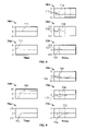
- FIG. 4 shows an embodiment of a plurality of plots that may be used for reducing an effect of a disturbance.
- FIG. 5 shows a plurality of exemplary graphs that may be used in reducing an effect of a disturbance.
- FIG. 6 is a block diagram of an exemplary dynamic disturbance rejection system (DDRS) that may be used with the system shown in FIG. 1 .
- DDRS dynamic disturbance rejection system
- FIG. 7 is a block diagram of an alternative embodiment of a DDRS, which may be used with the system shown in FIG. 1 .
- FIG. 8 illustrates a plurality of graphs showing system response illustrating an exemplary effect of basic control without dynamic disturbances.
- FIG. 9 illustrates a plurality of graphs showing system response illustrating an exemplary effect of disturbance signals without applying the method of reducing an effect of a disturbance.
- FIG. 10 illustrates a plurality of graphs showing system response illustrating an exemplary effect of disturbance signals and applying the method of reducing an effect of a disturbance.
- FIG. 1 is a block diagram of an exemplary system 10 that may be used to facilitate reducing an effect of a disturbance.
- system 10 includes a controller 12 , a dynamic disturbance reduction system (DDRS) 14 , and a dynamic system 16 .
- DDRS dynamic disturbance reduction system
- the term controller is not limited to just those integrated circuits referred to in the art as a controller, but broadly refers to a computer, a processor, a microcontroller, a microcomputer, a programmable logic controller, an application specific integrated circuit, and other programmable circuits.
- examples of DDRS 14 include, but are not limited to, a controller, a computer, a processor, a microcontroller, a microcomputer, a programmable logic controller, an application specific integrated circuit, and other programmable circuits.
- An example of dynamic system 16 includes, but is not limited to, a water tank, a gas tank, an engine system, such as, an internal combustion engine, a diesel engine, or a gas turbine used in power plants or alternatively aircraft propulsion, and a vehicle. Examples of the vehicle include a car, an airplane, a truck, and a motorcycle.
- Dynamic system 16 can be a single-input-single-output (SISO) system or alternatively system 16 can be a multiple-input-multiple-output (MIMO) system.
- Dynamic system 16 may include a magnet, an electrical device, a mechanical device, and/or a chemical substance. Dynamic system 16 may be implemented in, but is not limited to being implemented in, aerospace industry, marine industry, paper industry, automotive industry, plastic industry, food industry, and/or pharmaceutical industry.
- Controller 12 receives from a supervisory system, such as a person or supervisory computer, via an input device, a discrete controller input signal 18 or R k , which is a signal in a discrete time domain, and processes the input signal 18 or R k to output a discrete controller output signal 20 or v k , which is a signal in the discrete time domain.
- the variable k is an integer.
- Controller 12 receives controller input signal 18 from the person via an input device, or from a supervisory computer across a communication device, or from a supervisory algorithm in-situ with the discrete controller 12 .
- An example of the input device includes a mouse, keyboard, or any other analog or digital communication device.
- An example of a process performed by controller 12 on discrete controller input signal 18 includes integration, filtering, and/or determining a rate of change of information within discrete controller input signal 18 .
- An example of discrete controller input signal 18 includes a signal representative of a thrust demand, which is an amount of thrust, of a propulsion system and a power demand, which is an amount of power, of a power plant.
- Other examples of discrete controller input signal 18 include a signal representative of a rate of change of an altitude and a rate of change of speed.
- Examples of discrete controller output signal 20 include a signal representative of a rate of the thrust demand, a rate of change of the power demand, a rate of change of fuel flow, and a rate of change of an exhaust nozzle area.
- DDRS 14 receives discrete controller output signal 20 and a discrete disturbance signal 22 or d k , which is a signal in the discrete time domain. DDRS 14 reduces an effect of discrete disturbance signal 22 on a dynamic system output signal 24 or y k , which is a signal in the discrete time domain, by generating a discrete DDRS output signal 26 or u k , which is a signal in the discrete time domain.
- Examples of discrete dynamic system output signal 24 include a signal representative of an engine pressure ratio (EPR) across an engine within dynamic system 16 , a thrust output by dynamic system 16 , a speed of dynamic system 16 , a power of dynamic system 16 , and/or an increase or decrease in a level of fluid within a fluid tank.
- EPR engine pressure ratio
- Examples of discrete disturbance signal 22 include a signal representative of a flow of air, a flow of fuel, a flow of water, or a flow of chemical into dynamic system 16 , at least one environmental ambient condition, such as humidity or condensation, due to weather or an operating condition surrounding dynamic system 16 , a temperature or alternatively pressure of the atmosphere surrounding dynamic system 16 , a flow of energy from an actuator or alternatively an effector into dynamic system 16 , and/or a variable geometry, such as a plurality of variable stator vanes, a plurality of variable guide vanes, a plurality of variable by-pass ratios, which change basic physical relationships in dynamic system 16 .
- a sensor such as a position sensor, a flow sensor, a temperature sensor or a pressure sensor, measures a parameter, such as a position, a flow, a temperature or alternatively a pressure, of a sub-system, such as a tire or an engine, within dynamic system 16 to generate discrete disturbance signal 22 .
- a sensor such as a position sensor, a flow sensor, a temperature sensor or a pressure sensor, measures a parameter, such as a position, a flow, a temperature or alternatively a pressure, of a sub-system, such as a tire or an engine, within dynamic system 16 to generate discrete disturbance signal 22 .
- discrete disturbance signal 22 can be estimated or calculated by an estimation algorithm executed by a controller.
- discrete disturbance signal 22 can be a temperature calculated or estimated, by the estimation algorithm and the estimation algorithm calculates or estimates the temperature by using information from one or a combination of sensors including a speed sensor, a pressure sensor that senses a pressure at a location within or alternatively outside dynamic system 16 , and a plurality of temperatures sensors that sense temperatures at a plurality of locations in dynamic system 16 .
- a memory device such as a random access memory (RAM) or a read-only memory (ROM)
- an output device such as a display, which can be a liquid crystal display (LCD) or a cathode ray tube (CRT).
- LCD liquid crystal display
- CRT cathode ray tube
- FIG. 2 is a block diagram of a dynamic apparatus 50 , which is an example of dynamic system 16 .
- exemplary dynamic apparatus 50 is a Multiple-Input Multiple-Output (MIMO) dynamic apparatus that receives a plurality of discrete dynamic apparatus input signals 52 and 54 , receives a plurality of discrete dynamic apparatus disturbance signals 56 and 58 , and generates a plurality of discrete dynamic apparatus output signals 60 and 62 based on input signals 52 and 54 and/or disturbance signals 56 and 58 .
- MIMO Multiple-Input Multiple-Output
- Each discrete dynamic apparatus input signal 52 and 54 is an example of DDRS output signal 26 (shown in FIG. 1 ).
- each discrete dynamic apparatus disturbance signal 56 and 58 is an example of disturbance signal 22 (shown in FIG.
- each discrete dynamic apparatus output signal 60 and 62 is an example of discrete dynamic system output signal 24 .
- dynamic apparatus 50 receives any number of discrete dynamic apparatus input signals, and outputs any number of discrete dynamic apparatus output signals based on the discrete dynamic apparatus input signals and discrete dynamic apparatus disturbance signals.
- FIG. 3 is a block diagram of an alternative embodiment of a dynamic system 16 that may be used with system 10 (shown in FIG. 1 ).
- Dynamic system 16 includes an integrator 100 and a plant 102 .
- An example of plant 102 includes an engine, such as a turbine engine or a car engine, and/or an electronic commutated motor.
- Integrator 100 receives discrete DDRS output signal 26 , and integrates discrete DDRS output signal 26 to generate a discrete integrator output signal 104 .
- Plant 102 receives discrete integrator output signal 104 and generates discrete dynamic system output signal 24 based on output signal 104 and disturbance signal 22 .
- a turbine engine outputs thrust based on a signal representing an amount of fuel flow to the turbine engine and based on its environmental operating conditions.
- a vehicle engine outputs rotations per minute (RPM) of a vehicle based on a signal representing an amount of fuel flowing to the vehicle engine and the conditions in which the vehicle is operating.
- RPM rotations per minute
- x t is a state of a portion, such as a level of fluid within the fluid tank, an engine speed, or an engine temperature, of dynamic system 16
- t is continuous time
- ⁇ dot over (x) ⁇ t is a derivative, with respect to the time t, of the state x t
- u t is a DDRS output signal, which is a continuous form of the discrete DDRS output signal u k
- d t is a disturbance signal, which is a continuous form of the discrete disturbance signal d k
- y t is a dynamic system output signal 24 , which is a continuous form of the discrete dynamic system output signal y k .
- DDRS 14 linearizes the function f represented by equation (1) by applying:
- ⁇ dot over (x) ⁇ t is a derivative, with respect to time t, of the state x t , is a derivative, with respect to time t, of the nominal state value x t , is a derivative, with respect to time t, of the incremental state variable
- x ⁇ t , ⁇ f ⁇ x t ⁇ x _ t , d _ t , u _ t is a partial derivative of the function f, with respect to x t and is evaluated at x t , d t , and ⁇ t ,
- ⁇ f ⁇ u t ⁇ x _ t , d _ t , u _ t is a partial derivative of the function ⁇ , with respect to u t and is evaluated at x t , d t , and ⁇ t , and
- DDRS 14 expands the function h represented by equation (2) by applying:
- ⁇ h ⁇ x t ⁇ x _ t , d _ t , u _ t is a partial derivative of the function h, with respect to x t and is evaluated at x t , d t , and ⁇ t ,
- ⁇ h ⁇ u t ⁇ x _ t , d _ t , u _ t is a partial derivative of the function h, with respect to u t and is evaluated at x t , d t , and ⁇ t , and
- ⁇ h ⁇ d t ⁇ x _ t , d _ t , u _ t is a partial derivative of the function h, with respect to d t and is evaluated at x t , d t , and ⁇ t .
- DDRS 14 represents a change in the state x t as a function of a change in DDRS output signal u t and a change in the disturbance signal d t by representing the derivative of the incremental state variable ⁇ tilde over (x) ⁇ t as a function of the incremental disturbance variable ⁇ tilde over (d) ⁇ t and a function of the incremental input variable ⁇ t as:
- x ⁇ . t f ⁇ ( x _ t , u _ t , d _ t ) + ⁇ f ⁇ x t ⁇ x _ t , d _ t , u _ t ⁇ x ⁇ t + ⁇ f ⁇ u t ⁇ x _ t , d _ t , u _ t ⁇ u ⁇ t + ⁇ f ⁇ d t ⁇ x _ t , d _ t , u _ t ⁇ d ⁇ t - x _ . t ( 9 )
- DDRS 14 derives equation (9) by making ⁇ tilde over ( ⁇ dot over (x) ⁇ t the subject of equation (7). Moreover, DDRS 14 represents a change in the dynamic system output signal y t as a function of a change in the DDRS output signal u t and a change in the disturbance signal d t by representing the incremental output variable ⁇ tilde over (y) ⁇ t as a function of the incremental disturbance variable ⁇ tilde over (d) ⁇ t and a function of the incremental input variable ⁇ t as:
- DDRS 14 derives equation (10) by making ⁇ tilde over (y) ⁇ t the subject of equation (8).
- x _ . t 0 when x t is a constant, an equilibrium solution, or a steady state of the portion of dynamic system 16 .
- ⁇ ( x t , ⁇ t , d t ) is also a constant regardless of the time t of evolution of representation of dynamic system 16
- DDRS 14 substitutes y t instead of h( x t , ⁇ t , d t ) a matrix C instead of
- DDRS 14 calculates a matrix A as being equal to I+A c t s , calculates a matrix B u to be equal to B cu t s , a matrix B d to be equal to B cd t s , F k to be equal to f( x t , ⁇ t , d t )t s , ⁇ tilde over (x) ⁇ k , an incremental discrete state, to be equal to a discrete form of ⁇ tilde over (x) ⁇ t , ⁇ k , an incremental discrete DDRS output signal 26 , to be equal to a discrete form of ⁇ t , and ⁇ tilde over (d) ⁇ k , an incremental discrete disturbance signal, to be a discrete form of ⁇ tilde over (d) ⁇ t , t s is a sampling time or the sampling period, I is an identity matrix, and ⁇ tilde over (x) ⁇ k+1 is
- ⁇ tilde over (x) ⁇ k+1 of equation (14) can also be represented as a difference between a discrete state x k+1 and x k , where x k+1 is a discrete state of the portion of dynamic system 16 sampled during a sampling period k+1 and is generated one sampling period after x k is generated, and ⁇ tilde over (x) ⁇ k is the incremental discrete state.
- a microprocessor or a controller samples x k from x t with the sampling period t s , samples y k from y t with the sampling period t s , samples u k from u t with the sampling period t s , and samples d k from d t with the sampling period t s . It is noted that d k , u k , x k , and y k are samples that are sampled at the same time or during the same sampling period k.
- DDRS 14 formulates a desired response of dynamic system 16 as being a first order desired response.
- the relative degree one system takes one sample period to change an output of dynamic system 16 based on an input to dynamic system 16 .
- ⁇ tilde over (y) ⁇ k+1 is a future incremental discrete dynamic system output from dynamic system 16 one sample after the current sample ⁇ tilde over (y) ⁇ k is output from dynamic system 16
- ⁇ tilde over (v) ⁇ k is an incremental discrete controller output signal obtained as a difference between the discrete controller output signal v k and a nominal discrete controller output signal v k , which is a particular value of the discrete controller output signal v k at the reference time.
- the relative degree one dynamic system is an example of dynamic system 16 .
- ⁇ tilde over (d) ⁇ k+1 can also be represented as a difference between d k+1 and d k , where d k+1 is a discrete disturbance signal input to dynamic system 16 during a sampling period k+1, and is generated one sampling period after d k is generated, and ⁇ k+1 can also be represented as a difference between u k+1 and u k , where u k+1 is a discrete DDRS output signal output by DDRS 14 during a sampling period k+1, and is generated one sampling period after u k is generated.
- Equation (21) is a discrete form of the relation expressed by equation (3).
- u k ⁇ 1 is a discrete DDRS output signal output by DDRS 14 at k ⁇ 1 and generated one sampling period before u k is output by DDRS 14
- ⁇ k is a discrete form in the discrete time domain of ⁇ t .
- DDRS 14 substitutes equation (23) into equation (24), substitutes K 1 instead of
- ⁇ 1 ( ⁇ D d ⁇ CB d ) in equation (24) to generate: u k u k ⁇ 1 +K 1 ⁇ tilde over (v) ⁇ k +K 3 F k +K d ⁇ tilde over (d) ⁇ k (25)
- DDRS 14 computes K d at least one of before and during energization of dynamic system 16 .
- DDRS 14 computes K d on-line in real time while dynamic system 16 is being operated by a power source.
- DDRS 14 computes K d off-line before dynamic system 16 is provided power by the power source.
- DDRS 14 changes u k at the same time the disturbance signal d t is input to dynamic system 16 . Accordingly, an impact of the disturbance signal d t on dynamic system 16 is reduced.
- ⁇ ( 1 - ts ⁇ )
- ⁇ is a time constant of dynamic system 16
- ⁇ tilde over (y) ⁇ k+2 is an incremental discrete dynamic system output signal
- ⁇ tilde over (y) ⁇ k+2 can also be represented as a difference between a dynamic system output signal y k+2 output by dynamic system 16 and y k+1 , where y k+2 is sampled during a sampling period k+2 and is generated one sampling period after y k+1 is generated.
- DDRS 14 formulates a desired response of dynamic system 16 as being the second order desired response.
- the relative degree two system takes two sample periods to change an output of dynamic system 16 based on an input to dynamic system 16 .
- an input to dynamic system 16 is u k
- the relative degree one system outputs y k+2 , which is two sample periods after y k .
- DDRS 14 generates equations (26)-(34) based on the relative degree two system.
- the relative degree two system is an example of dynamic system 16 .
- ⁇ tilde over (d) ⁇ k+2 is an incremental discrete disturbance signal and can also be represented as a difference between a discrete disturbance signal d k+2 input to dynamic system 16 and d k+1 , where d k+2 is sampled during a sampling period k+2 and is generated one sampling period after d k+1 is generated, and F k+1 is generated during a sampling period k+1, which is one sampling period after F k is generated.
- u ⁇ k ⁇ CAB u ⁇ - 1 ⁇ ⁇ ( 1 - ⁇ ) ⁇ t s ⁇ v ⁇ k + [ ( 1 + ⁇ ) ⁇ CA - CA 2 - ⁇ ⁇ ⁇ C ] ⁇ x ⁇ k + [ ( 1 + ⁇ ) ⁇ C - CA ] ⁇ F k - CF k + 1 ⁇ ⁇ ⁇ + [ ( 1 + ⁇ ) ⁇ CB d - CAB d - ⁇ ⁇ D d ] ⁇ d ⁇ k + [ ( 1 + ⁇ ) ⁇ D d - CB d ] ⁇ d ⁇ k + [ ( 1 + ⁇ ) ⁇ D d - CB d ] ⁇ d ⁇ k + 1 - D d ⁇ d ⁇ k + 2 ⁇ ( 31 )
- Equation (32) is calculated, by DDRS 14 , based on values of the derivative ⁇ dot over (x) ⁇ t or an estimation algorithm that computes the derivative ⁇ dot over (x) ⁇ t at the current sample x t .
- u ⁇ k ⁇ CAB u ⁇ - 1 ⁇ ⁇ ( 1 - ⁇ ) ⁇ t s ⁇ v ⁇ k + [ ( 1 + ⁇ ) ⁇ CA - CA 2 - ⁇ ⁇ ⁇ C ] ⁇ x ⁇ k + [ ⁇ ⁇ ⁇ C - CA ] ⁇ F k ⁇ ⁇ ⁇ + [ ( ⁇ - 1 ) ⁇ CB d + ( ⁇ - 1 ) ⁇ D d - CAB d ] ⁇ d ⁇ k ⁇ ( 33 )
- DDRS 14 substitutes K 5 as being
- DDRS 14 formulates an n th order desired response of dynamic system 16 , where n is an integer greater than two.
- DDRS 14 calculates the first, second, or alternatively the nth order desired response upon receiving a selection, via the input device, regarding a number, such as 1, 2 or alternatively n th , of a desired response.
- a number such as 1, 2 or alternatively n th
- v t is a continuous form of v k .
- DDRS 14 generates an incremental form of equation (36) to output the first order desired response.
- DDRS 14 upon receiving from the person via the input device that a desired response is second order, DDRS 14 applies an Euler's approximation to a combination of an integrator and the first order desired response of dynamic system 16 .
- DDRS 14 generates an incremental form of equation (38) to output the second desired response.
- FIG. 4 shows an embodiment of a plurality of plots 300 , 302 , 304 , and 306 that may be used for reducing an effect of a disturbance.
- DDRS 14 calculates and may generate plot 300 , which is an example of d k corresponding to the relative degree one system versus the time t.
- DDRS 14 calculates and may generate plot 302 , which is an example of ⁇ tilde over (d) ⁇ k plotted versus the time t and which is generated as a difference between d k and d k ⁇ 1 , where d k ⁇ 1 is a discrete disturbance signal input to dynamic system 16 and measured by a sensor, such as a temperature or a pressure sensor, one sampling period before d k is measured by the sensor.
- a sensor such as a temperature or a pressure sensor
- DDRS 14 calculates and may generate plot 304 , which is an example of ⁇ tilde over (d) ⁇ k+1 plotted versus the time t and which is generated as a difference between d k+1 and d k , where ⁇ tilde over (d) ⁇ k+1 is an incremental discrete disturbance signal at k+1, where d k+1 1 is a discrete disturbance signal input to dynamic system 16 and measured by a sensor, such as a temperature or a pressure sensor, one sampling period before d k is measured by the sensor.
- a sensor such as a temperature or a pressure sensor
- DDRS 14 calculates and may generate plot 306 , which is an example of ⁇ tilde over (d) ⁇ k+2 plotted versus the time t and which is generated as a difference between ⁇ tilde over (d) ⁇ k+2 and ⁇ tilde over (d) ⁇ k+1 , where ⁇ tilde over (d) ⁇ k+2 is an incremental discrete disturbance signal at k+2, where d k+2 is a discrete disturbance signal input to dynamic system 16 and measured by a sensor, such as a temperature or a pressure sensor, one sampling period before d k+1 is measured by the sensor.
- a sensor such as a temperature or a pressure sensor
- FIG. 5 shows a plurality of exemplary graphs 310 and 312 that may be used to facilitate reducing an effect of a disturbance.
- Graph 310 includes plots 302 , 304 , and 306
- graph 312 illustrates a plot of a ratio 314 , versus the time t, of plots 304 and 302 , and a ratio 316 , versus the time t, of plots 306 and 302 .
- DDRS 14 determines ⁇ tilde over (d) ⁇ k+n from ⁇ tilde over (d) ⁇ k in a similar manner in which ⁇ tilde over (d) ⁇ k+1 and ⁇ tilde over (d) ⁇ k+2 are determined from ⁇ tilde over (d) ⁇ k .
- FIG. 6 is a block diagram of an exemplary DDRS 500 , which maybe used with system 10 (shown in FIG. 1 ) as a replacement for DDRS 14 .
- DDRS 500 may be used in system 10 to replace DDRS 14 .
- DDRS 500 includes a subtractor 502 , a plurality of adders 504 and 506 , a plurality of multipliers 508 , 510 , 512 , 514 , 516 , and 520 , and where K 1 , K 3 , and K d are from equation (25).
- Multiplier 508 receives the discrete disturbance signal d k and multiples d k with 1/z, which is an inverse z-transform, to output the discrete disturbance signal d ⁇ 1 .
- Subtractor 502 receives the discrete disturbance signal d k and the discrete disturbance signal d k ⁇ 1 , subtracts the discrete disturbance signal d k ⁇ 1 from the discrete disturbance signal d k to output the incremental discrete disturbance signal ⁇ tilde over (d) ⁇ k .
- Multiplier 510 multiplies the incremental discrete disturbance signal ⁇ tilde over (d) ⁇ k with K d to output a multiplier output signal 518 .
- Multiplier 520 multiplies the derivative ⁇ dot over (x) ⁇ t of the state x t with t s to output F k .
- Multiplier 514 receives F k and multiplies F k with K 3 to output a multiplier output signal 522 .
- Multiplier 512 receives v k and multiplies v k with K 1 to output a multiplier output signal 524 .
- Adder 504 receives multiplier output signals 518 , 522 , and 524 , adds the multiplier output signals 518 , 522 , and 524 to generate an adder output signal 526 , which is U k ⁇ U k ⁇ 1 in equation (25) and is equal to ⁇ k .
- Multiplier 516 receives u k and multiplies u k with 1/z to output u k ⁇ 1 .
- Adder 506 adds ⁇ k and u k ⁇ 1 to output u k .
- an initial value, such as zero, of u k is provided by the person to DDRS 14 via the input device.
- adder 506 outputs additional values of u k .
- Dynamic system 16 receives u k from DDRS 14 and u k reduces an effect of d k on y k .
- FIG. 7 is a block diagram of an alternative embodiment of a DDRS 600 , that may be used with system 10 (shown in FIG. 1 ) as a replacement for DDRS 14 .
- DDRS 600 includes subtractor 502 , adders 504 , and 506 , a plurality of multipliers 602 , 604 , and 606 , and multipliers 508 , 516 , and 520 .
- Multiplier 602 multiplies the incremental discrete disturbance signal ⁇ tilde over (d) ⁇ k with K e to output a multiplier output signal 608 .
- Multiplier 606 receives F k and multiplies F k with K 7 to output a multiplier output signal 610 .
- Multiplier 604 receives v k and multiplies v k with K 5 to output a multiplier output signal 612 .
- Adder 504 receives multiplier output signals 608 , 610 , and 612 , adds the multiplier output signals 608 , 610 , and 612 to generate an adder output signal 614 , which is u k ⁇ u k ⁇ 1 in equation (34) and is equal to ⁇ k .
- Dynamic system 16 receives u k from DDRS 14 and u k reduces an effect of d k on y k . It is noted that K 1 , K 3 , K d , K 5 , K 7 , and K e change based on a degree of dynamic system and based on other factors, such as the time constant ⁇ .
- FIG. 8 shows a plurality of exemplary graphs 700 , 702 , 704 , 706 , and 708 including a plurality of exemplary outputs from dynamic system 16 .
- Graph 700 plots a disturbance signal 710 versus time t
- graph 702 illustrates a plot of a disturbance signal 712 versus the time t
- graph 704 represents a dynamic system output signal 714 versus time t and a desired response 716 of dynamic system 16 versus time t.
- graph 706 illustrates a plot of a dynamic system output signal 718 versus time t and a desired response 720 of dynamic system 16 versus time t.
- graph 708 illustrates a plot of a dynamic system output signal 722 versus time t and a desired response 724 of dynamic system 16 versus time t.
- dynamic system 16 When disturbance signals 710 and 712 are input to dynamic system 16 and no disturbance is applied to dynamic system 16 , dynamic system 16 generates dynamic system output signals 714 , 718 , and 722 .
- a difference between dynamic system output signal 714 and desired response 716 is small and dynamic system output signal 714 quickly converges to desired response 716 .
- a coupling between desired response 720 and dynamic system output signal 718 is small, such as 9%-12%.
- a coupling between desired response 724 and dynamic system output signal 722 is small, such as 9%-12%.
- FIG. 9 illustrates a plurality of exemplary graphs 750 , 752 , 754 , 756 , and 758 .
- Graph 750 illustrates a plot of a disturbance signal 760 versus the time t
- graph 752 illustrates a plot of a disturbance signal 762 versus the time t
- graph 754 illustrates a plot of a dynamic system output signal 764 versus the time t and a desired response 766 of a dynamic system, which is not coupled to DDRS 14 , versus the time t.
- graph 756 illustrates a plot of a dynamic system output signal 770 versus the time t and a desired response 768 of a dynamic system, which is not coupled to DDRS 14 , versus the time t.
- graph 758 illustrates a plot of a dynamic system output signal 774 versus the time t and a desired response 772 of a dynamic system, which is not coupled to DDRS 14 , versus the time t.
- the dynamic system When disturbance signals 760 and 762 are input to a dynamic system, which is not coupled to DDRS 14 , the dynamic system generates dynamic system output signals 764 , 770 , and 774 .
- a dynamic system output signal 764 slowly converges to desired response 766 .
- a coupling between desired response 770 and dynamic system output signal 770 is large, such as 38%-42%.
- a coupling between desired response 772 and dynamic system output signal 774 is large, such as 38%-42%.
- FIG. 10 illustrates a plurality of exemplary graphs 800 , 802 , 804 , 806 , and 808 .
- Graph 800 illustrates a plot of a disturbance signal 810 versus the time t
- graph 802 illustrates a plot of a disturbance signal 812 versus the time t
- graph 804 illustrates a plot of a dynamic system output signal 814 versus the time t and a desired response 816 of dynamic system 16 versus the time t
- graph 806 illustrates a plot of a dynamic system output signal 818 versus the time t and a desired response 820 of dynamic system 16 versus the time t.
- the coupling between desired response 820 and dynamic system output signal 818 is similar to that between desired response 720 and dynamic system output signal 718
- the coupling between desired response 824 and dynamic system output signal 822 is similar to that between desired response 724 and dynamic system output signal 722 when no disturbance is present.
- DDRS 14 does not wait to receive y k ⁇ 1 to generate u k and changes u k at the same time or during the same sampling period as d k is received by dynamic system 16 . Hence, an effect of d k is reduced on dynamic system 16 before d k enters and adversely affects dynamic system 16 .
Abstract
Description
{dot over (x)} t =ƒ(x t ,u t ,d t) (1)
y t =h(x t ,u t ,d t) (2)
x t =
u t =ū t +ũ t. (4)
y t =
d t =
is a partial derivative of the function f, with respect to xt and is evaluated at
is a partial derivative of the function ƒ, with respect to ut and is evaluated at
is a partial derivative of the function ƒ, with respect to dt and is evaluated at
is a partial derivative of the function h, with respect to xt and is evaluated at
is a partial derivative of the function h, with respect to ut and is evaluated at
is a partial derivative of the function h, with respect to dt and is evaluated at
substitutes Ac instead of
substitutes Bcu instead of
and Bcd instead of
in equation (9) to generate:
when
a matrix Du instead of
and a matrix Dd instead of
of in equation (10) to generate:
{tilde over (y)} t =C{tilde over (x)} t +D u ũ t +D d {tilde over (d)} t (13)
{tilde over (x)} k+1 =A{tilde over (x)} k +B u ũ k +B d {tilde over (d)} k +F k (14)
{tilde over (y)} k =C{tilde over (x)} k +D u ũ k +D d {tilde over (d)} k (15)
{tilde over (y)} k+1 −{tilde over (y)} k =t s {tilde over (v)} k (16)
{tilde over (y)} k+1 =C{tilde over (x)} k+1 +D u ũ k+1 +D d {tilde over (d)} k+1 (17)
{tilde over (y)} k+1 =CA{tilde over (x)} k +CB u ũ k +CB d {tilde over (d)} k +CF k +D d {tilde over (d)} k+1. (18)
CA{tilde over (x)} k +CB u ũ k +CB d {tilde over (d)} k +D d {tilde over (d)} k+1 +CF k −C{tilde over (x)} k −D d {tilde over (d)} k =st{tilde over (v)} k (19)
ũ k =|CB u|−1 {t s {tilde over (v)} k+(C−CA){tilde over (x)} k+(D d −CB d){tilde over (d)} k −D d {tilde over (d)} k+1 −CF k} (20)
x k =
{tilde over (x)}k=0 (22)
ũ k =|CB u|−1 {t s {tilde over (v)} k −CF k+(−D d −CB d){tilde over (d)} k} (23)
u k =u k−1 +ũ k (24)
u k =u k−1 +K 1 {tilde over (v)} k +K 3 F k +K d {tilde over (d)} k (25)
{tilde over (y)} k+2−(1+α){tilde over (y)} k+1 +α{tilde over (y)} k=(1−α)t s {tilde over (v)} k (26)
τ is a time constant of dynamic system 16, {tilde over (y)}k+2 is an incremental discrete dynamic system output signal, and {tilde over (y)}k+2 can also be represented as a difference between a dynamic system output signal yk+2 output by dynamic system 16 and yk+1, where yk+2 is sampled during a sampling period k+2 and is generated one sampling period after yk+1 is generated. If dynamic system 16 is a relative degree two system, DDRS 14 formulates a desired response of dynamic system 16 as being the second order desired response. The relative degree two system takes two sample periods to change an output of dynamic system 16 based on an input to dynamic system 16. For example, when an input to dynamic system 16 is uk, the relative degree one system outputs yk+2, which is two sample periods after yk. DDRS 14 generates equations (26)-(34) based on the relative degree two system. The relative degree two system is an example of dynamic system 16.
{tilde over (y)} k+1 =CA{tilde over (x)} k +CB d {tilde over (d)} k +CF k +D d {tilde over (d)} k+1 (27)
{tilde over (y)} k+2 =CA{tilde over (x)} k+1 +CB d {tilde over (d)} k+1 +CF k+1 +D d {tilde over (d)} k+2 (28)
{tilde over (y)} k+2 =CA{A{tilde over (x)} k +B u ũ k +B d {tilde over (d)} k +F k }+CB d {tilde over (d)} k+1 +CF k+1 +D d {tilde over (d)} k+2 (29)
F k+1 =t sƒ(
u k =u k−1 +K 5 {tilde over (v)} k +K 7 F k +K e {tilde over (d)} k (34)
{dot over (y)}t=vt (35)
y k+1 −y k =t s v k (36)
τÿ t +{dot over (y)} t =v t (37)
y k+2−(1+α)y k+1 +αy k=(1−α)t s v k (38)
Claims (17)
Priority Applications (2)
| Application Number | Priority Date | Filing Date | Title |
|---|---|---|---|
| US11/549,320 US7421354B2 (en) | 2006-10-13 | 2006-10-13 | Systems and methods for reducing an effect of a disturbance |
| US11/925,145 US20080221710A1 (en) | 2006-10-13 | 2007-10-26 | System and methods for reducing an effect of a disturbance |
Applications Claiming Priority (1)
| Application Number | Priority Date | Filing Date | Title |
|---|---|---|---|
| US11/549,320 US7421354B2 (en) | 2006-10-13 | 2006-10-13 | Systems and methods for reducing an effect of a disturbance |
Related Child Applications (1)
| Application Number | Title | Priority Date | Filing Date |
|---|---|---|---|
| US11/925,145 Continuation-In-Part US20080221710A1 (en) | 2006-10-13 | 2007-10-26 | System and methods for reducing an effect of a disturbance |
Publications (2)
| Publication Number | Publication Date |
|---|---|
| US20080091375A1 US20080091375A1 (en) | 2008-04-17 |
| US7421354B2 true US7421354B2 (en) | 2008-09-02 |
Family
ID=39304044
Family Applications (1)
| Application Number | Title | Priority Date | Filing Date |
|---|---|---|---|
| US11/549,320 Expired - Fee Related US7421354B2 (en) | 2006-10-13 | 2006-10-13 | Systems and methods for reducing an effect of a disturbance |
Country Status (1)
| Country | Link |
|---|---|
| US (1) | US7421354B2 (en) |
Cited By (6)
| Publication number | Priority date | Publication date | Assignee | Title |
|---|---|---|---|---|
| US20120040298A1 (en) * | 2010-08-16 | 2012-02-16 | Emerson Process Management Power & Water Solutions, Inc. | Steam Temperature Control Using Dynamic Matrix Control |
| CN102374519A (en) * | 2010-08-16 | 2012-03-14 | 爱默生过程管理电力和水解决方案公司 | Dynamic tuning of dynamic matrix control of steam temperature |
| US8876483B2 (en) | 2010-01-14 | 2014-11-04 | Neptco, Inc. | Wind turbine rotor blade components and methods of making same |
| US9163828B2 (en) | 2011-10-31 | 2015-10-20 | Emerson Process Management Power & Water Solutions, Inc. | Model-based load demand control |
| US9217565B2 (en) | 2010-08-16 | 2015-12-22 | Emerson Process Management Power & Water Solutions, Inc. | Dynamic matrix control of steam temperature with prevention of saturated steam entry into superheater |
| US10137542B2 (en) | 2010-01-14 | 2018-11-27 | Senvion Gmbh | Wind turbine rotor blade components and machine for making same |
Families Citing this family (4)
| Publication number | Priority date | Publication date | Assignee | Title |
|---|---|---|---|---|
| CN103780174A (en) * | 2014-01-09 | 2014-05-07 | 北京科诺伟业科技股份有限公司 | Method for suppressing voltage fluctuation and flicker caused by wind power |
| CA3069523A1 (en) | 2017-07-11 | 2019-01-17 | Actym Therapeutics, Inc. | Engineered immunostimulatory bacterial strains and uses thereof |
| EP3820992A2 (en) | 2018-07-11 | 2021-05-19 | Actym Therapeutics, Inc. | Engineered immunostimulatory bacterial strains and uses thereof |
| EP3844276A2 (en) | 2018-08-28 | 2021-07-07 | Actym Therapeutics, Inc. | Engineered immunostimulatory bacterial strains and uses thereof |
Citations (14)
| Publication number | Priority date | Publication date | Assignee | Title |
|---|---|---|---|---|
| US5627896A (en) | 1994-06-18 | 1997-05-06 | Lord Corporation | Active control of noise and vibration |
| US5796849A (en) | 1994-11-08 | 1998-08-18 | Bolt, Beranek And Newman Inc. | Active noise and vibration control system accounting for time varying plant, using residual signal to create probe signal |
| US6460001B1 (en) * | 2000-03-29 | 2002-10-01 | Advantest Corporation | Apparatus for and method of measuring a peak jitter |
| US6665526B2 (en) * | 1999-12-22 | 2003-12-16 | Mitsubishi Denki Kabushiki Kaisha | Multipath noise reducer, audio output circuit, and FM receiver |
| US6735538B1 (en) * | 2000-03-29 | 2004-05-11 | Advantest Corporation | Apparatus and method for measuring quality measure of phase noise waveform |
| US20040117692A1 (en) * | 2002-12-13 | 2004-06-17 | Sweet Charles M. | High speed capture and averaging of serial data by asynchronous periodic sampling |
| US6823253B2 (en) | 2002-11-27 | 2004-11-23 | General Electric Company | Methods and apparatus for model predictive control of aircraft gas turbine engines |
| US6823675B2 (en) | 2002-11-13 | 2004-11-30 | General Electric Company | Adaptive model-based control systems and methods for controlling a gas turbine |
| US20040260492A1 (en) * | 2003-06-19 | 2004-12-23 | Francine Halle | Direct jitter analysis of binary sampled data |
| US6863497B2 (en) | 2002-04-02 | 2005-03-08 | Rolls-Royce Deutschland Ltd & Co Kg | Stator vane span attachment for a gas turbine |
| US6882889B2 (en) | 2002-12-02 | 2005-04-19 | United Technologies Corporation | Constrained dynamic inversion control algorithm |
| US20050193739A1 (en) | 2004-03-02 | 2005-09-08 | General Electric Company | Model-based control systems and methods for gas turbine engines |
| US20060238151A1 (en) * | 2004-03-30 | 2006-10-26 | Brother Kogyo Kabushiki Kaisha | Image forming apparatus using noise-resistant motor control device |
| US20070162161A1 (en) | 2006-01-09 | 2007-07-12 | Aditya Kumar | Multivariable controller design method for multiple input/outputs systems with multiple input/output constraints |
-
2006
- 2006-10-13 US US11/549,320 patent/US7421354B2/en not_active Expired - Fee Related
Patent Citations (15)
| Publication number | Priority date | Publication date | Assignee | Title |
|---|---|---|---|---|
| US5627896A (en) | 1994-06-18 | 1997-05-06 | Lord Corporation | Active control of noise and vibration |
| US5796849A (en) | 1994-11-08 | 1998-08-18 | Bolt, Beranek And Newman Inc. | Active noise and vibration control system accounting for time varying plant, using residual signal to create probe signal |
| US6665526B2 (en) * | 1999-12-22 | 2003-12-16 | Mitsubishi Denki Kabushiki Kaisha | Multipath noise reducer, audio output circuit, and FM receiver |
| US6460001B1 (en) * | 2000-03-29 | 2002-10-01 | Advantest Corporation | Apparatus for and method of measuring a peak jitter |
| US6735538B1 (en) * | 2000-03-29 | 2004-05-11 | Advantest Corporation | Apparatus and method for measuring quality measure of phase noise waveform |
| US6863497B2 (en) | 2002-04-02 | 2005-03-08 | Rolls-Royce Deutschland Ltd & Co Kg | Stator vane span attachment for a gas turbine |
| US6823675B2 (en) | 2002-11-13 | 2004-11-30 | General Electric Company | Adaptive model-based control systems and methods for controlling a gas turbine |
| US6823253B2 (en) | 2002-11-27 | 2004-11-23 | General Electric Company | Methods and apparatus for model predictive control of aircraft gas turbine engines |
| US6882889B2 (en) | 2002-12-02 | 2005-04-19 | United Technologies Corporation | Constrained dynamic inversion control algorithm |
| US20040117692A1 (en) * | 2002-12-13 | 2004-06-17 | Sweet Charles M. | High speed capture and averaging of serial data by asynchronous periodic sampling |
| US7143323B2 (en) * | 2002-12-13 | 2006-11-28 | Teradyne, Inc. | High speed capture and averaging of serial data by asynchronous periodic sampling |
| US20040260492A1 (en) * | 2003-06-19 | 2004-12-23 | Francine Halle | Direct jitter analysis of binary sampled data |
| US20050193739A1 (en) | 2004-03-02 | 2005-09-08 | General Electric Company | Model-based control systems and methods for gas turbine engines |
| US20060238151A1 (en) * | 2004-03-30 | 2006-10-26 | Brother Kogyo Kabushiki Kaisha | Image forming apparatus using noise-resistant motor control device |
| US20070162161A1 (en) | 2006-01-09 | 2007-07-12 | Aditya Kumar | Multivariable controller design method for multiple input/outputs systems with multiple input/output constraints |
Non-Patent Citations (1)
| Title |
|---|
| Brunell, Brent J., GT2004-53780, Model Adaptation and Nonlinear Model Predictive Control of an Aircraft Engine, Proceedings of Turbo Expo 2004, ASME Turbo Expo, Jun. 14-17, 2004, pp. 1-10, Vienna Austria. |
Cited By (15)
| Publication number | Priority date | Publication date | Assignee | Title |
|---|---|---|---|---|
| US9394882B2 (en) | 2010-01-14 | 2016-07-19 | Senvion Gmbh | Wind turbine rotor blade components and methods of making same |
| US9429140B2 (en) | 2010-01-14 | 2016-08-30 | Senvion Gmbh | Wind turbine rotor blade components and methods of making same |
| US10137542B2 (en) | 2010-01-14 | 2018-11-27 | Senvion Gmbh | Wind turbine rotor blade components and machine for making same |
| US8876483B2 (en) | 2010-01-14 | 2014-11-04 | Neptco, Inc. | Wind turbine rotor blade components and methods of making same |
| US9945355B2 (en) | 2010-01-14 | 2018-04-17 | Senvion Gmbh | Wind turbine rotor blade components and methods of making same |
| CN102374518B (en) * | 2010-08-16 | 2015-03-18 | 爱默生过程管理电力和水解决方案公司 | Steam temperature control using dynamic matrix control |
| CN102374518A (en) * | 2010-08-16 | 2012-03-14 | 爱默生过程管理电力和水解决方案公司 | Steam temperature control using dynamic matrix control |
| US9335042B2 (en) * | 2010-08-16 | 2016-05-10 | Emerson Process Management Power & Water Solutions, Inc. | Steam temperature control using dynamic matrix control |
| US20120040298A1 (en) * | 2010-08-16 | 2012-02-16 | Emerson Process Management Power & Water Solutions, Inc. | Steam Temperature Control Using Dynamic Matrix Control |
| CN102374519B (en) * | 2010-08-16 | 2015-07-22 | 爱默生过程管理电力和水解决方案公司 | Dynamic tuning of dynamic matrix control of steam temperature |
| US9447963B2 (en) | 2010-08-16 | 2016-09-20 | Emerson Process Management Power & Water Solutions, Inc. | Dynamic tuning of dynamic matrix control of steam temperature |
| US9217565B2 (en) | 2010-08-16 | 2015-12-22 | Emerson Process Management Power & Water Solutions, Inc. | Dynamic matrix control of steam temperature with prevention of saturated steam entry into superheater |
| CN102374519A (en) * | 2010-08-16 | 2012-03-14 | 爱默生过程管理电力和水解决方案公司 | Dynamic tuning of dynamic matrix control of steam temperature |
| US9163828B2 (en) | 2011-10-31 | 2015-10-20 | Emerson Process Management Power & Water Solutions, Inc. | Model-based load demand control |
| US10190766B2 (en) | 2011-10-31 | 2019-01-29 | Emerson Process Management Power & Water Solutions, Inc. | Model-based load demand control |
Also Published As
| Publication number | Publication date |
|---|---|
| US20080091375A1 (en) | 2008-04-17 |
Similar Documents
| Publication | Publication Date | Title |
|---|---|---|
| US7421354B2 (en) | Systems and methods for reducing an effect of a disturbance | |
| US20080221710A1 (en) | System and methods for reducing an effect of a disturbance | |
| EP2267559B1 (en) | Method and system for combining feedback and feedforward in model predictive control | |
| Brenner et al. | Overview of recent flight flutter testing research at NASA Dryden | |
| US6229898B1 (en) | Active vibration control system using on-line system identification with enhanced noise reduction | |
| US8682000B2 (en) | Method and device for narrow-band noise suppression in a vehicle passenger compartment | |
| EP0152019A2 (en) | Method for controlling fuel injection for engine | |
| CN111271181A (en) | Two-degree-of-freedom [ mu ] controller for conservative gain reduction scheduling of aero-engine | |
| GB2321720A (en) | Modelling a system with more parameters than sensors | |
| Morelli et al. | Real-time dynamic modeling: data information requirements and flight-test results | |
| Kiencke | A view of automotive control systems | |
| DeCastro | Rate-based model predictive control of turbofan engine clearance | |
| US20100131252A1 (en) | Apparatus and methods for simulating a system steady state devoid of performing full transient operating conditions | |
| Brunell et al. | Model adaptation and nonlinear model predictive control of an aircraft engine | |
| Breikin et al. | Regularisation approach for real-time modelling of aero gas turbines | |
| Volponi | Use of hybrid engine modeling for on-board module performance tracking | |
| Kegerise et al. | Real-time feedback control of flow-induced cavity tones—Part 1: Fixed-gain control | |
| Takahashi et al. | A simple engine model for idle speed control | |
| EP1898063B1 (en) | Method and device for estimation of variables, in particular during operation of a motor vehicle | |
| Chang et al. | Hybrid gain data assimilation using variational corrections in the subspace orthogonal to the ensemble | |
| CN111305954A (en) | Input-limited aero-engine conservative robust gain reduction scheduling controller | |
| US8682627B2 (en) | Estimating a stream temperature in a turbojet | |
| CN111443595B (en) | Aeroengine gain scheduling controller based on health degradation | |
| Kiencke | The role of automatic control in automotive systems | |
| Haley et al. | Generalized Predictive Control for Active Flutter Suppression |
Legal Events
| Date | Code | Title | Description |
|---|---|---|---|
| AS | Assignment |
Owner name: GENERAL ELECTRIC COMPANY, NEW YORK Free format text: ASSIGNMENT OF ASSIGNORS INTEREST;ASSIGNOR:BRUNELL, BRENT JEROME;REEL/FRAME:018389/0195 Effective date: 20061005 |
|
| STCF | Information on status: patent grant |
Free format text: PATENTED CASE |
|
| FEPP | Fee payment procedure |
Free format text: PAYOR NUMBER ASSIGNED (ORIGINAL EVENT CODE: ASPN); ENTITY STATUS OF PATENT OWNER: LARGE ENTITY |
|
| FPAY | Fee payment |
Year of fee payment: 4 |
|
| FPAY | Fee payment |
Year of fee payment: 8 |
|
| FEPP | Fee payment procedure |
Free format text: MAINTENANCE FEE REMINDER MAILED (ORIGINAL EVENT CODE: REM.); ENTITY STATUS OF PATENT OWNER: LARGE ENTITY |
|
| LAPS | Lapse for failure to pay maintenance fees |
Free format text: PATENT EXPIRED FOR FAILURE TO PAY MAINTENANCE FEES (ORIGINAL EVENT CODE: EXP.); ENTITY STATUS OF PATENT OWNER: LARGE ENTITY |
|
| STCH | Information on status: patent discontinuation |
Free format text: PATENT EXPIRED DUE TO NONPAYMENT OF MAINTENANCE FEES UNDER 37 CFR 1.362 |
|
| FP | Lapsed due to failure to pay maintenance fee |
Effective date: 20200902 |