US7324044B2 - Object locator - Google Patents
Object locator Download PDFInfo
- Publication number
- US7324044B2 US7324044B2 US10/910,267 US91026704A US7324044B2 US 7324044 B2 US7324044 B2 US 7324044B2 US 91026704 A US91026704 A US 91026704A US 7324044 B2 US7324044 B2 US 7324044B2
- Authority
- US
- United States
- Prior art keywords
- object locator
- location
- location data
- receiver
- block
- Prior art date
- Legal status (The legal status is an assumption and is not a legal conclusion. Google has not performed a legal analysis and makes no representation as to the accuracy of the status listed.)
- Expired - Fee Related, expires
Links
Images


Classifications
-
- G—PHYSICS
- G01—MEASURING; TESTING
- G01S—RADIO DIRECTION-FINDING; RADIO NAVIGATION; DETERMINING DISTANCE OR VELOCITY BY USE OF RADIO WAVES; LOCATING OR PRESENCE-DETECTING BY USE OF THE REFLECTION OR RERADIATION OF RADIO WAVES; ANALOGOUS ARRANGEMENTS USING OTHER WAVES
- G01S5/00—Position-fixing by co-ordinating two or more direction or position line determinations; Position-fixing by co-ordinating two or more distance determinations
- G01S5/0009—Transmission of position information to remote stations
- G01S5/0018—Transmission from mobile station to base station
- G01S5/0027—Transmission from mobile station to base station of actual mobile position, i.e. position determined on mobile
-
- A—HUMAN NECESSITIES
- A01—AGRICULTURE; FORESTRY; ANIMAL HUSBANDRY; HUNTING; TRAPPING; FISHING
- A01K—ANIMAL HUSBANDRY; CARE OF BIRDS, FISHES, INSECTS; FISHING; REARING OR BREEDING ANIMALS, NOT OTHERWISE PROVIDED FOR; NEW BREEDS OF ANIMALS
- A01K27/00—Leads or collars, e.g. for dogs
- A01K27/009—Leads or collars, e.g. for dogs with electric-shock, sound, magnetic- or radio-waves emitting devices
-
- G—PHYSICS
- G01—MEASURING; TESTING
- G01S—RADIO DIRECTION-FINDING; RADIO NAVIGATION; DETERMINING DISTANCE OR VELOCITY BY USE OF RADIO WAVES; LOCATING OR PRESENCE-DETECTING BY USE OF THE REFLECTION OR RERADIATION OF RADIO WAVES; ANALOGOUS ARRANGEMENTS USING OTHER WAVES
- G01S19/00—Satellite radio beacon positioning systems; Determining position, velocity or attitude using signals transmitted by such systems
- G01S19/01—Satellite radio beacon positioning systems transmitting time-stamped messages, e.g. GPS [Global Positioning System], GLONASS [Global Orbiting Navigation Satellite System] or GALILEO
- G01S19/13—Receivers
- G01S19/14—Receivers specially adapted for specific applications
- G01S19/16—Anti-theft; Abduction
-
- G—PHYSICS
- G01—MEASURING; TESTING
- G01S—RADIO DIRECTION-FINDING; RADIO NAVIGATION; DETERMINING DISTANCE OR VELOCITY BY USE OF RADIO WAVES; LOCATING OR PRESENCE-DETECTING BY USE OF THE REFLECTION OR RERADIATION OF RADIO WAVES; ANALOGOUS ARRANGEMENTS USING OTHER WAVES
- G01S19/00—Satellite radio beacon positioning systems; Determining position, velocity or attitude using signals transmitted by such systems
- G01S19/01—Satellite radio beacon positioning systems transmitting time-stamped messages, e.g. GPS [Global Positioning System], GLONASS [Global Orbiting Navigation Satellite System] or GALILEO
- G01S19/13—Receivers
- G01S19/14—Receivers specially adapted for specific applications
- G01S19/17—Emergency applications
-
- G—PHYSICS
- G01—MEASURING; TESTING
- G01S—RADIO DIRECTION-FINDING; RADIO NAVIGATION; DETERMINING DISTANCE OR VELOCITY BY USE OF RADIO WAVES; LOCATING OR PRESENCE-DETECTING BY USE OF THE REFLECTION OR RERADIATION OF RADIO WAVES; ANALOGOUS ARRANGEMENTS USING OTHER WAVES
- G01S19/00—Satellite radio beacon positioning systems; Determining position, velocity or attitude using signals transmitted by such systems
- G01S19/01—Satellite radio beacon positioning systems transmitting time-stamped messages, e.g. GPS [Global Positioning System], GLONASS [Global Orbiting Navigation Satellite System] or GALILEO
- G01S19/13—Receivers
- G01S19/34—Power consumption
-
- G—PHYSICS
- G08—SIGNALLING
- G08B—SIGNALLING OR CALLING SYSTEMS; ORDER TELEGRAPHS; ALARM SYSTEMS
- G08B21/00—Alarms responsive to a single specified undesired or abnormal condition and not otherwise provided for
- G08B21/02—Alarms for ensuring the safety of persons
- G08B21/0202—Child monitoring systems using a transmitter-receiver system carried by the parent and the child
- G08B21/0241—Data exchange details, e.g. data protocol
- G08B21/0247—System arrangements wherein the alarm criteria uses signal strength
-
- G—PHYSICS
- G08—SIGNALLING
- G08B—SIGNALLING OR CALLING SYSTEMS; ORDER TELEGRAPHS; ALARM SYSTEMS
- G08B21/00—Alarms responsive to a single specified undesired or abnormal condition and not otherwise provided for
- G08B21/02—Alarms for ensuring the safety of persons
- G08B21/0202—Child monitoring systems using a transmitter-receiver system carried by the parent and the child
- G08B21/0261—System arrangements wherein the object is to detect trespassing over a fixed physical boundary, e.g. the end of a garden
-
- G—PHYSICS
- G08—SIGNALLING
- G08B—SIGNALLING OR CALLING SYSTEMS; ORDER TELEGRAPHS; ALARM SYSTEMS
- G08B21/00—Alarms responsive to a single specified undesired or abnormal condition and not otherwise provided for
- G08B21/02—Alarms for ensuring the safety of persons
- G08B21/0202—Child monitoring systems using a transmitter-receiver system carried by the parent and the child
- G08B21/0269—System arrangements wherein the object is to detect the exact location of child or item using a navigation satellite system, e.g. GPS
-
- G—PHYSICS
- G01—MEASURING; TESTING
- G01S—RADIO DIRECTION-FINDING; RADIO NAVIGATION; DETERMINING DISTANCE OR VELOCITY BY USE OF RADIO WAVES; LOCATING OR PRESENCE-DETECTING BY USE OF THE REFLECTION OR RERADIATION OF RADIO WAVES; ANALOGOUS ARRANGEMENTS USING OTHER WAVES
- G01S19/00—Satellite radio beacon positioning systems; Determining position, velocity or attitude using signals transmitted by such systems
- G01S19/01—Satellite radio beacon positioning systems transmitting time-stamped messages, e.g. GPS [Global Positioning System], GLONASS [Global Orbiting Navigation Satellite System] or GALILEO
- G01S19/13—Receivers
- G01S19/35—Constructional details or hardware or software details of the signal processing chain
- G01S19/36—Constructional details or hardware or software details of the signal processing chain relating to the receiver frond end
-
- G—PHYSICS
- G01—MEASURING; TESTING
- G01S—RADIO DIRECTION-FINDING; RADIO NAVIGATION; DETERMINING DISTANCE OR VELOCITY BY USE OF RADIO WAVES; LOCATING OR PRESENCE-DETECTING BY USE OF THE REFLECTION OR RERADIATION OF RADIO WAVES; ANALOGOUS ARRANGEMENTS USING OTHER WAVES
- G01S2205/00—Position-fixing by co-ordinating two or more direction or position line determinations; Position-fixing by co-ordinating two or more distance determinations
- G01S2205/001—Transmission of position information to remote stations
- G01S2205/008—Transmission of position information to remote stations using a mobile telephone network
Definitions
- the present disclosure pertains generally to electronic personal locating devices for determining the location or position of a pet, an object or a person, and more particularly, a device for determining the location or position of the object by utilizing the capabilities of two-way paging systems and global positioning satellite systems.
- GPS global positioning system
- the position of an individual truck is determined by coincident reception of signals from at least three GPS satellites by a satellite receiver, which position can then be stored or can be transmitted to a central receiving station via some sort of wireless link.
- the wireless link can be a two-way communication link wherein the positioning information is only transmitted in response to receiving a request.
- GPS global positioning system
- the global positioning system has some disadvantages in that it is relatively slow in acquiring the location data and it is strongly dependent upon the target object being in an open area where it is in a line of sight position relative to at least three GPS satellites.
- a further disadvantage, particularly in a small, portable unit, is that the GPS receiver that must be included in a locating device requires the use of substantial electrical energy during the period in which the location information is being acquired and developed from the GPS system. Further, a small portable object locator, in addition to minimizing the use of electrical power while being subject to less than ideal orientations to enable quick and efficient location by the GPS system, must also be very simple and easy to use.
- the object locator described in the present disclosure and claimed herein comprises an apparatus and a method for locating or tracking an individual, an object or an animal having attached thereto an object locator operable to communicate with a base station location via a two-way paging system and further operable to acquire location information downloaded from a GPS system.
- a query for location information about the individual object or animal may be transmitted from the base station over the paging system to a paging receiver integrated with the object locator.
- a signal enabling a GPS receiver in the object locator to acquire the location information for the position of the individual, object or animal from the GPS system is generated in the object locator.
- the GPS receiver and the object locator receive the location information from the GPS system and store it in a memory in the object locator.
- the GPS receiver in the object locator may then be disabled to conserve power.
- the location information stored in the memory of the object locator may then be loaded into a paging transmitter, also integrated with the object locator, and transmitted via the paging system to the base station.
- the location information for the individual, the object or the animal may be output in some form that is readable or useful to a person at the base station or to a person who has access to the base station or to a person accessible to the base station.
- FIG. 1 illustrates a block diagram of an object locator system of the present disclosure.
- FIG. 2 illustrates a pictorial example of an object locator according to the present disclosure
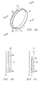
- FIGS. 3 a - 3 c illustrate a pictorial drawing of an object locator supported by a collar according to the present disclosure
- FIG. 4 illustrates a block diagram of the object locator of the present disclosure
- FIG. 5 illustrates a flowchart of the operation of the object locator generally
- FIG. 6 illustrates a flowchart of the operation of the object locator subject to an additional external control
- FIG. 7 illustrates a pictorial drawing of a range dependent enablement system used to provide external control for the object locator
- FIG. 8 illustrates a block diagram of a base station that may be used with the object locator of the present disclosure
- FIG. 9 illustrates a block diagram of an alternate embodiment of a base station that may be used with the object locator of the present disclosure.
- FIG. 10 illustrates a flowchart of the operation of the object locator system of the present disclosure in obtaining location data via two-way paging.
- the object locator system 10 includes a two-way paging system 12 , a global positioning satellite system 50 and the object locator 42 .
- the two-way paging system 12 is a conventional paging system that is well known in the art, for example, such as illustrated and described in U.S. Pat. No. 5,423,056 issued Jun. 6, 1995 to Lindquist, et al. and entitled ADAPTIVE CELLULAR PAGING SYSTEM, which patent is incorporated by reference herein in its entirety.
- the two-way paging system 12 interacts with a base station 18 over a transmit path 14 and a receive path 16 .
- the base station 18 may include a telephone, pager, and the like or may have an input 20 for receiving a dialed-in telephone number from telephone set 24 along communications path 22 or from wireless telephone set 25 over communications path 31 .
- the input 20 is responsive to dual tone multi-frequency (DTMF) tones transmitted by telephone set 24 .
- Base station 18 further has an output 26 from which location data to be displayed travels along path 28 to display 30 .
- Display 30 may be configured to display location information in any of several forms, for example, text, figures, graphics, or numbers.
- the object locator system 10 of the present disclosure includes an object locator 42 .
- object locator 42 In one of its operational modes, as a two-way paging transceiver, object locator 42 includes an input 40 coupled to an antenna 36 along cable 38 for receiving signals transmitted by two-way paging system 12 along path 32 and for transmitting paging signals to the two-way paging system 12 along path 34 .
- the object locator 42 also includes an input 44 for receiving from a global positioning satellite (GPS) system 50 location information signals along path 52 to be intercepted by antenna 48 and conducted to the object locator 42 along path 46 to input 44 .
- GPS global positioning satellite
- the global positioning satellite system 50 is of a conventional design well known in the art, an example of which is described in U.S. Pat. No.
- location information signals may be received from the Glasnost satellite system by the use of a receiving system configured for such reception.
- object locator 42 is intended to be carried or attached to an individual, an object or an animal to be located or tracked by the object locator system of the present disclosure.
- a user enters the system from the base station 18 by dialing the telephone number address corresponding to the object locator 42 , which functions as a paging transceiver, on telephone set 24 .
- the DTMF signal then travels along path 22 to input 20 of base station 18 where it is converted to a paging transmit signal and transmitted from antenna 15 along transmit path 14 to the two-way paging system 12 .
- the two-way paging system 12 relays the paging message via transmit path 32 to the antenna 36 coupled to the object locator 42 .
- the object locator 42 processes the request for location information transmitted by base station 18 , obtains location information from the global positioning satellite system 50 and transmits a response containing the location information from antenna 36 along path 34 to the two-way paging system 12 which, in turn, relays the location information signal along path 16 to antenna 15 of the base station 18 for processing and display on display 30 .
- wireless paths 14 and 16 along with antenna 15 may instead each comprise a standard telephone connection to a central office.
- FIG. 2 there is illustrated a pictorial drawing of an object locator 42 as it may be typically configured with a two-way paging antenna 36 and a GPS receive antenna 48 .
- the two-way paging antenna 36 is coupled to object locator 42 along cable 38 to an input 40 on the object locator 42 .
- the GPS receive antenna 48 is coupled along a cable 46 to an input 44 on the object locator 42 .
- the two-way paging antenna 36 shown in FIG. 2 is intended to represent the fact that this antenna in the object locator 42 is typically of the type found with two-way paging equipment. Such an antenna is typically mounted internal to the pager unit itself and is thereby necessarily of very small dimension.
- the object locator 42 of the present disclosure may be optimized by the use of an external antenna such as shown in FIG. 2 .
- the GPS receive antenna 48 is conventionally referred to as a “patch antenna” because of its flat, thin, rectangular shaped design.
- a patch antenna is intended to be disposed on an upward, relatively level surface in order to expose it to receive the relatively weak signals transmitted by the global positioning satellite system from the satellites arrayed in the GPS system.
- the illustration in FIG. 2 thus demonstrates that both of the antennae used in the system may be positioned for optimal reception and transmission and connected to the object locator 42 using the flexible cables 38 and 46 respectively for the two-way paging antennae 36 and the GPS receive antenna 48 .
- FIGS. 3 a , 3 b and 3 c there is illustrated a pictorial drawing of an object locator 42 mounted on the lower side of a collar 45 .
- a collar 45 is configured for supporting an object locator 42 around the body or neck of an animal which is intended to be tracked or located by the object locator 10 of the present disclosure.
- the GPS antenna 48 is attached to the collar diametrically opposite the position of the object locator. This is intentional as will be described hereinbelow.
- the object locator is coupled to the GPS antenna 48 through a cable 46 which connects to the input 44 of the object locator 42 .
- This arrangement is illustrated in FIG. 3 a and may be more clearly shown by looking at the cross section A-A′ illustrated in FIG.
- Section A-A′ a side view of the object locator mounted on a collar is shown wherein collar 45 supports the object locator 42 at its lower point and supports the GPS antenna 48 at its diametrically opposite upper point. As before, the GPS antenna 48 is coupled through cable 46 to input 44 of the object locator 42 .
- a side view identified by cross section B-B′ in FIG. 3 c shows the opposite side of the collar-mounted object locator 42 assembly.
- Section B-B there is shown the collar 45 which supports the object locator 42 at its lower end and the patch antenna or GPS antenna 48 at its diametrically opposite upper end.
- Section B-B′ Also shown in the Section B-B′ is a representation of the two-way paging antenna 36 which is coupled to input 40 of the object locator 42 . It will be appreciated that many configurations are possible for arranging or attaching the object locator and its antennae to the collar 45 , including consolidating the locator and antenna as a unit locatably mounted on or in the collar. Alternatively, the locator and antenna may be distributively arranged on or in the collar.
- the greater mass of the object locator 42 relative to the mass of the GPS antenna 48 and the fact that they are mounted on diametrically opposite sides of the collar 45 enables the object locator 42 to always remain in the lowest possible position and the GPS receiving antenna to always remain in the highest possible position to optimize the reception from the GPS system 50 .
- the mechanism such as a clasp or buckle arrangement whereby the collar 45 may be opened and closed to secure the collar around the neck or body of the animal to be tracked or located.
- a paging receiver 60 is shown coupling a data output 62 along path 64 to an input of controller 66 .
- Controller 66 includes a memory 68 for the storage of location data and a battery 70 for powering the object locator 42 .
- This battery 70 is, in the present disclosure, a rechargeable battery.
- This battery 70 can be a NiCad battery or a Lithium battery.
- a solar cell 71 is provided for charging the battery 70 .
- Controller 66 includes a control output 72 which is coupled along path 74 to a control input 76 of paging receiver 60 .
- Paging receiver 60 receives paging communications via antenna 36 R which are coupled along cable 38 R to RF input 40 R of paging receiver 60 .
- GPS receiver 78 for which provision is made to couple location data at an output 80 along path 82 to an input terminal 84 of controller 66 .
- GPS receiver 78 further includes an enable input which is coupled from controller 66 at output 86 along path 88 to the enable input 90 of the GPS receiver 78 .
- the GPS receiver 78 receives GPS signals from the global positioning satellite system 50 at antenna 48 which signals are coupled along path 46 to RF input 44 of the GPS receiver 78 .
- a paging transmitter 92 which is configured to transmit the location data provided by controller 66 at output 98 along path 96 to the data input 94 of paging transmitter 92 .
- Controller 66 also provides an enable output at output 100 along path 102 to the enable input 104 of paging transmitter 92 .
- the paging transmitter 92 when enabled, transmits data received at the data input 94 and couples the signal to be transmitted from the output terminal 40 T along path 38 T to the paging transmitter antenna 36 T for radiation to the two-way paging system 12 . It will be appreciated that the paging system components, while shown as separate functional elements in FIG.
- FIG. 4 may in fact be integrated into a single two-way paging transceiver which share a common antenna represented by reference number 36 .
- the illustration shown in FIG. 4 is intended to provide clarity as to the signal paths that operate during the communication relationship of the object locator 42 with the two-way paging system 12 .
- a number of configurations for coupling the antenna to the paging transceiver are feasible, are well known in the art and will not be described further herein.
- signal detector 106 having an output 108 which is coupled along path 110 to an enable input 112 of controller 66 .
- the signal detector 106 represents any of several optional devices which may enable the more precise control of the object locator 42 by limiting the operation of the object locator 42 to certain external conditions outside the paging communications or the GPS reception areas by the object locator 42 .
- the signal detector 106 provides an output whenever a threshold is crossed by signal energy from an independent source. Such threshold, for example, may represent a limiting point beyond which the object locator 42 is enabled to operate.
- Such a threshold may represent a distance within which a position of the object locator will probably provide no useful information since the object locator may be within line of sight to the base station, for example.
- Other thresholds may be expressed in terms of time or altitude or as an azimuth heading.
- the object locator 42 may be programmed for operating an alarm when the object locator 42 moves outside a perimeter.
- Such perimeter may be programmed by physically positioning the object locator 42 at extremes of an area and, while the GPS 78 receiver is operating, storing in the object locator's memory 68 the coordinates reported, thus establishing a boundary outside of which the object locator 42 will automatically report a position.
- the perimeter may be defined by at least one coordinate stored in the object locator memory 68 . The perimeter is then determined by selecting stored algorithms to define the limits of a circular or other geometrical shape outside of which the object locator 42 will automatically report a position.
- each of the major functional blocks shown in FIG. 4 may be implemented by means of integrated circuitry which may be configured to fit within a housing of very small dimensions. For example, a pocket pager that typically occupies a volume of approximately three to five cubic inches may weigh approximately four to six ounces.
- the controller 66 may comprise a single chip microprocessor or microcontroller or digital signal processor which may be programmed to provide a variety of functions and operational features. Such programs may be stored in memory 68 for use by the controller 66 in controlling the operation of the object locator 42 .
- the paging receiver 60 , the paging transmitter 92 and the GPS receiver 78 while shown as functional blocks, in reality, each may have a number of complex functions incorporated therein.
- FIG. 5 there is illustrated a flowchart for the operation of the object locator 42 shown in FIG. 4 in the case where the user desires to determine the location of the object locator 42 .
- This circumstance may represent any number of user activities including an owner's efforts to determine the location of a pet dog or a pet cat, for example.
- the operation illustrated in FIG. 5 may also include a situation where an owner desires to track versus time, an object to which the object locator 42 is attached.
- the flowchart of FIG. 5 may also illustrate the situation when the object locator 42 is attached to a person and it is desired to know the location of that person at some particular time or some other previous time as further described below.
- the flow begins at block 202 with the start of the sequence of operations, which is followed by decision block 204 in which the object locator 42 seeks to determine whether a page requesting location information has been received by the input 40 of the two-way paging receiver 60 . If the result of this determination is in the negative, then the flow returns to the input of the decision block for a retry. If, however, the result of the query was affirmative, then the flow proceeds to block 206 in which the GPS receiver 78 is enabled to acquire the location coordinates of the object locator 42 by receiving signals from the global positioning satellite system 50 illustrated in FIG. 1 .
- the object locator 42 Upon successfully acquiring the coordinates of the object locator 42 and thus of the individual object or animal to which the object locator 42 is attached, the object locator 42 then operates to store the coordinate information in block 208 by loading the coordinate information into the memory 68 of the controller 66 in the object locator 42 .
- coordinate information may be associated with a time stamp.
- time stamp derived from the GPS satellite system, may then be stored in block 208 for later retrieval. Additionally, such coordinate information may further be associated with other data such as object locator 42 operational status or battery condition.
- the flow then proceeds from block 208 , where the coordinates were stored in the memory 68 , to block 210 , wherein the object locator 42 is configured to transmit the coordinates in response to the request received over the two-way paging system 12 .
- the transmission of coordinates will occur in the opposite direction utilizing the same two-way paging system 12 over which the request for location coordinates was received in block 204 .
- the flow proceeds to a timer block 212 which provides a measured interval of time during which the object locator 42 attempts to acquire the coordinates at the particular time from the GPS system 50 .
- a typical GPS system often takes a substantial amount of time to acquire location coordinate information from a sufficient number of satellites in order to fix the location of the object locator 42 with a sufficient degree of precision.
- the time required involves receiving several signals under conditions which may vary widely from instant to instant, which impairs the ability of the GPS receiver 78 as shown in FIG. 4 to obtain complete location data to respond to the request received by the paging receiver 60 in the object locator 42 .
- the time value represented by the timer operating in block 212 may be on the order of five to ten minutes, for example. In block 212 , if the timer has not reached the time-out value, then the flow returns to the input of block 206 where the object locator 42 again attempts to acquire the coordinates from the GPS system 50 .
- FIG. 5 thus illustrates a basic mode of operation of the object locator 42 . It will be appreciated that many variations on this basic operating mode are possible and may be used to enhance the operation of the object locator 42 . Such features may be programmed into the controller 66 of the object locator 42 .
- FIG. 6 there is illustrated a flowchart for the operation of the object locator 42 in the circumstance where it is activated to obtain location information from the GPS receiver 78 only, in this illustrative example, when the object locator 42 is in a position beyond a distance limit relative to the base station or some other defined location from which the request for location coordinates was initiated.
- the flowchart in FIG. 6 also shows additional steps in the operational sequence which may be used to enable and disable the GPS receiver 78 within the object locator 42 .
- the GPS receiver 78 is typically a device which requires substantial electrical power to operate and so it is to the advantage of the object locator system 10 of the present disclosure to attempt to minimize the power drawn from the object locator battery 70 in FIG. 4 . This may be accomplished by limiting the operating cycle of the GPS receiver 78 to become operational only long enough to obtain the coordinate information that is required by the object locator 42 .
- the flow begins in FIG. 6 with a start block 220 from which the flow proceeds to a block 222 , wherein the object locator 42 determines whether the object locator 42 is beyond a predetermined limit such as a minimum distance from the base station or other defined location making the request for location information. If the determination is in the negative, that is, the object locator 42 is not beyond the predetermined limit, then the flow returns to the input of the decision block 222 for another attempt. This looping will continue as long as the object locator 42 is within the predetermined limit established by circuitry within the object locator 42 and other portions of the object locator system 10 of the present disclosure. The functional operation of an illustrative example of such a predetermined limit feature will be described further hereinbelow in conjunction with FIG. 7 .
- the flow proceeds from start block 220 to a decision block 222 to determine whether the object locator 42 has received a query from the base station 18 . If a query has not been received, the flow proceeds along the “N” path to a timer block 224 wherein the object locator 42 may operate a timed sequence to periodically enable the GPS receiver 78 to acquire location coordinates whether or not a query is received from the base station 18 . When the timer of block 224 times out, the flow proceeds along the “Y” path to a block 226 to enable the GPS receiver 78 .
- decision block, 222 if the object locator 42 did receive a query from the base station 18 , the flow proceeds along the “Y” path to block 226 to enable the GPS receiver 78 .
- the flow in the object locator 42 proceeds from block 226 to block 228 to acquire the coordinates of the location of the object locator 42 . Thereafter, the flow proceeds to decision block 229 to determine whether the object locator 42 is beyond a predetermined limit with respect to the base station 18 . If the result of the determination in block 229 is negative, the flow proceeds along the “N” path to decision block 231 wherein a counter provides for a predetermined number of trials to establish whether the object locator 42 is beyond the predetermined limit required in block 229 . When the counter in block 231 completes the last count, the flow proceeds along the “Y” path to the input of the decision block 222 .
- the flow proceeds along the “Y” path to block 230 to store the location coordinates acquired from the GPS satellite during the step performed in block 228 , wherein the enable signal applied to the enable terminal 90 thus operates to awaken the GPS receiver 78 so that it may communicate with the GPS system and obtain location information coordinates for the object locator 42 .
- the flow proceeds from block 226 where the GPS receiver 78 is enabled to a block 228 where the object locator 42 acquires the coordinate information from the global positioning satellite system 50 .
- the controller 66 within the object locator 42 upon acquiring the coordinates of the object locator 42 from the GPS receiver 78 , the controller 66 within the object locator 42 causes the location information to be stored in the memory 68 of the object locator 42 in the operational block 230 of FIG. 6 .
- the flow then proceeds to a block 232 where the controller 66 operates to disable the GPS receiver 78 such that it will no longer continue to drain power from the battery, until the next time that it is desired to acquire coordinate information from the GPS system 50 .
- the flow proceeds to a block 234 wherein the object locator 42 provides the location data on output terminal 98 along path 96 to the data input 94 of the paging transmitter 92 .
- the location information is then transmitted via the two-way paging system 12 to the base station 18 shown in FIG. 1 .
- the flow proceeds from block 234 following the transmission of the coordinate information to a time-out block 236 where a timer provides an interval of time in which the object locator 42 is permitted to acquire the coordinate information from the GPS system, thus maximizing the opportunity to acquire the coordinates before the object locator 42 becomes inactive.
- a timer provides an interval of time in which the object locator 42 is permitted to acquire the coordinate information from the GPS system, thus maximizing the opportunity to acquire the coordinates before the object locator 42 becomes inactive.
- the time-out value may again typically be on the order of five to ten minutes, although the time duration may legitimately be any value that corresponds with the particular circumstances of use and, in fact, may be adjustable in some applications.
- the operation loops back around to the input of the time-out block 236 and enables the object locator 42 to continue attempting to acquire the location information from the GPS system.
- the flow proceeds along the “Y” path from block 236 back to the start of the sequence at the input to the decision block 222 where the object locator 42 is enabled to check whether the object locator 42 is positioned beyond the predetermined limit as previously explained.
- FIG. 7 there is illustrated a pictorial block diagram of one configuration that is possible to provide the predetermined limit signal to the object locator 42 .
- a base station 18 coupled with its antenna 126 through a cable 128 and operating to produce a signal which is radiated according to the radiation pattern characteristic of the antenna 126 of the base station.
- an object locator 42 which includes a signal detector block 120 coupled to an antenna 122 through a cable 124 . It will be noted that the base station 18 is operating in a transmit mode and the object locator 42 is operating in a receive mode via antenna 122 .
- the object locator 42 by comparing the received signal strength of the signal transmitted by the base station from antenna 126 with a reference signal stored within the signal detector 120 , is able to make a determination as to where it is in relation to the base station in terms of the distance that separates the object locator 42 and the base station 18 . It is presumed in this example that the signal strength measured between the base station 18 and the object locator 42 falls off in a predictable manner as compared with the distance that separates the object locator 42 from the base station 18 .
- An alternative to comparing the limit signal with a reference value is to simply utilize the signal-to-noise characteristics of the receiver in the object locator 42 .
- a limit is thereby provided.
- the limit may be adjusted simply by adjusting the base station signal strength.
- a predetermined limit may thus be established by controlling the signal strength of the base station 18 signal such that at an imaginary boundary 130 surrounding base station 18 is defined.
- the signal strength is of a sufficiently low value which can just be detected by the signal detector 120 in the object locator 42 at the imaginary boundary 130 .
- the object locator 42 antenna 122 is greater than a distance indicated by the radius “r” from the base station 18 , then no signal will be detected (or it will be below an acceptable threshold) and the object locator 42 is presumed to be beyond the predetermined limit represented by the distance “r”, which may be thought of as an acceptance radius. If, however, the object locator 42 receives or detects the signal emitted by the base station 18 (or it is above the predetermined threshold), then it is presumed that the antenna 122 of the object locator 42 is within the radius “r” and the object locator 42 must not be, at that point, activated to attempt to acquire location information from the GPS system 50 .
- the base station 302 includes a paging receiver 304 which has a receiving antenna 306 coupled to the paging receiver 304 by a cable 308 .
- the output of paging receiver 304 is supplied at an output 310 along path 312 to an input 314 of a processor 316 which receives and processes the location information for output or display.
- a processor 316 which receives and processes the location information for output or display.
- the information is stored along a path 318 in a register 320 from which the information can be retrieved along path 322 by the processor 316 for output at terminal 324 along path 326 to the input 328 of a data display 330 .
- the location information is processed for display as data which may be in the form of degrees of longitude and latitude, the names of the closest major street intersections or in terms of polar coordinates such as an azimuth heading and a distance between the base station 302 and the object locator 42 .
- a base station 350 which includes a paging receiver 304 .
- Paging receiver 304 receives location information transmitted by object locator 42 to the antenna 306 of the paging receiver 304 along cable 308 .
- Paging receiver 304 is coupled from an output 352 along path 354 to an input 356 of processor 358 in the base station 350 .
- Processor 358 may also have access to a register 380 along path 378 from which the processor 358 may further obtain stored location information along path 382 from register 380 .
- Such location information is, of course, available from the GPS receiver 368 which is coupled at an output 370 along path 372 to an input 374 to processor 358 .
- This GPS receiver 368 is part of base station 350 and enables the base station 350 to provide an enhanced display of the location information obtained from the object locator 42 .
- a GPS display 366 that obtains data concerning the location coordinates from processor 358 at an output 360 which flows along path 362 to an input to the GPS display 366 at input 364 .
- the GPS display 366 is configured to provide a map of the area that includes both the base station 350 and the object locator 42 , and thus display the relative position of each component of the object locator system 10 with respect to the other.
- a map may be shown with streets or thoroughfares indicated thereon and indicia included in the display showing the respective location of the base station 350 and of the object locator 42 .
- FIG. 10 there is shown a flowchart of the operation of the combined units of the object locator system 10 of the present disclosure as illustrated in FIG. 1 .
- the flow begins at block 402 where the routine starts and thereupon flows to a block 404 in which the base station 18 requests location information by paging the object locator 42 .
- the base station 18 transmits a request for location information to the object locator 42 .
- the flow proceeds from block 404 to block 412 where the object locator 42 proceeds through the sequence to enable the GPS receiver 78 in order to obtain new location coordinate information.
- the object locator 42 checks its own memory—see, for example, the block diagram of the object locator 42 shown in FIG.
- the flow proceeds to a block 424 wherein the base station 18 makes a determination as to whether it has received the requested coordinate information from the object locator 42 . If the result is affirmative, then the flow proceeds along the “Y” path to a block 428 where the base station 18 proceeds to output or display the coordinate information to the user at the base station 18 . Thereupon, the flow proceeds from block 428 to a block 430 wherein the routine ends.
- the base station 18 determines whether the most recent page of the object locator 42 was, in fact, the last attempt permitted within the protocol for the base station operation. If the result is affirmative, then the flow proceeds along the “Y” path to block 418 where the object locator 42 operates to disable the GPS receiver 78 so that it no longer uses power from the battery 70 of the object locator 42 and thereafter proceeds to block 430 where the routine ends. If, however, the result of the determination in block 426 was negative, then the flow returns to the start of the routine at the input to block 404 where the base station 18 re-attempts to page the object locator 42 .
- the object locator 42 checks to determine whether location coordinate information is, in fact, in the memory 68 of the object locator 42 . If the result is negative, the flow proceeds along the “N” path to block 414 where the object locator 42 acquires the new coordinate information and, as previously described, proceeds in block 416 to store the new coordinate information in memory 68 of the object locator 42 . The flow then returns to the input of block 412 wherein the GPS receiver 78 is enabled.
- the above noted object location system was disclosed as being utilized in conjunction with a pet, such that the pet owner can determine the location of their wayward pet.
- the locator as described hereinabove, in one embodiment, is triggered to determine the location of the pet in response to receiving a signal from a paging system.
- the paging system utilizes existing infrastructure in order to direct a message over a wireless link to a moving object, such as the pet. This only requires the inclusion of a paging receiver tuned to the frequency of the paging transmitters. Of course, there are multiple paging transmitters disposed about any given area. If the pet wandered outside of the range of all of these paging transmitters, then the system will not work. This would then, in the alternative, require a direct RF link to the pet.
- the locator 42 will do one of two things. First, it could merely search its own memory to determine if location coordinates are stored therein from a previous acquisition operation of the GPS system. If so, these could be transmitted back to the requester. Alternatively the GPS system is turned on in response to receiving the request and then the location determined. Of course, as described hereinabove, there are provisions made for situations wherein the GPS system cannot be acquired.
- the disclosed embodiment sets forth the use of a two-way pager.
- These two-way pagers are desirable in that they make use of the existing infrastructure of the paging system. This is facilitated by the inclusion of a plurality of receivers at each of the paging towers or paging “sticks” which allow the signal to be received and forwarded back to a central station. This central station then processes the information received and forwards it to the user.
- This information is in the form of coordinates. This coordinate information can then be relayed back to the user in any number of ways. It could actually be forwarded via a paging channel to the user, which might result in a latency of approximately two to five minutes.
- the two-way system that can be utilized is a conventional system, one example of such a conventional system described in U.S. Pat. No. 5,708,971, issued Jan. 13, 1998, entitled “TWO-WAY PAGING SYSTEM AND APPARATUS,” which is incorporated herein by reference.
Abstract
Description
Claims (18)
Priority Applications (2)
| Application Number | Priority Date | Filing Date | Title |
|---|---|---|---|
| US10/910,267 US7324044B2 (en) | 1999-06-18 | 2004-08-03 | Object locator |
| US12/021,192 US7564405B2 (en) | 1999-06-18 | 2008-01-28 | Object locator |
Applications Claiming Priority (5)
| Application Number | Priority Date | Filing Date | Title |
|---|---|---|---|
| US14004099P | 1999-06-18 | 1999-06-18 | |
| US09/362,788 US6172640B1 (en) | 1999-06-18 | 1999-07-28 | Pet locator |
| US09/678,345 US6421001B1 (en) | 1999-06-18 | 2000-10-03 | Object locator |
| US10/187,287 US6771213B2 (en) | 1999-06-18 | 2002-07-16 | Object locator |
| US10/910,267 US7324044B2 (en) | 1999-06-18 | 2004-08-03 | Object locator |
Related Parent Applications (1)
| Application Number | Title | Priority Date | Filing Date |
|---|---|---|---|
| US10/187,287 Continuation US6771213B2 (en) | 1999-06-18 | 2002-07-16 | Object locator |
Related Child Applications (1)
| Application Number | Title | Priority Date | Filing Date |
|---|---|---|---|
| US12/021,192 Continuation US7564405B2 (en) | 1999-06-18 | 2008-01-28 | Object locator |
Publications (2)
| Publication Number | Publication Date |
|---|---|
| US20050073409A1 US20050073409A1 (en) | 2005-04-07 |
| US7324044B2 true US7324044B2 (en) | 2008-01-29 |
Family
ID=26837819
Family Applications (5)
| Application Number | Title | Priority Date | Filing Date |
|---|---|---|---|
| US09/362,788 Expired - Fee Related US6172640B1 (en) | 1999-06-18 | 1999-07-28 | Pet locator |
| US09/678,345 Expired - Fee Related US6421001B1 (en) | 1999-06-18 | 2000-10-03 | Object locator |
| US10/187,287 Expired - Fee Related US6771213B2 (en) | 1999-06-18 | 2002-07-16 | Object locator |
| US10/910,267 Expired - Fee Related US7324044B2 (en) | 1999-06-18 | 2004-08-03 | Object locator |
| US12/021,192 Expired - Fee Related US7564405B2 (en) | 1999-06-18 | 2008-01-28 | Object locator |
Family Applications Before (3)
| Application Number | Title | Priority Date | Filing Date |
|---|---|---|---|
| US09/362,788 Expired - Fee Related US6172640B1 (en) | 1999-06-18 | 1999-07-28 | Pet locator |
| US09/678,345 Expired - Fee Related US6421001B1 (en) | 1999-06-18 | 2000-10-03 | Object locator |
| US10/187,287 Expired - Fee Related US6771213B2 (en) | 1999-06-18 | 2002-07-16 | Object locator |
Family Applications After (1)
| Application Number | Title | Priority Date | Filing Date |
|---|---|---|---|
| US12/021,192 Expired - Fee Related US7564405B2 (en) | 1999-06-18 | 2008-01-28 | Object locator |
Country Status (1)
| Country | Link |
|---|---|
| US (5) | US6172640B1 (en) |
Cited By (3)
| Publication number | Priority date | Publication date | Assignee | Title |
|---|---|---|---|---|
| US7764228B2 (en) | 1999-06-18 | 2010-07-27 | Pfizer, Inc. | Portable position determining device |
| US9467968B2 (en) | 2013-10-07 | 2016-10-11 | Ickovic & Bliss, Inc. | Wearable mobile broadcasting recovery system and device |
| US11778420B2 (en) | 2020-06-29 | 2023-10-03 | Ickovic & Bliss, Inc. | Systems, methods, and program products for digital PET identification |
Families Citing this family (209)
| Publication number | Priority date | Publication date | Assignee | Title |
|---|---|---|---|---|
| US6876947B1 (en) * | 1997-10-02 | 2005-04-05 | Fitsense Technology, Inc. | Monitoring activity of a user in locomotion on foot |
| US6889135B2 (en) | 1999-03-31 | 2005-05-03 | C2 Global Technologies, Inc. | Security and tracking system |
| US8321124B2 (en) | 1999-03-31 | 2012-11-27 | C2 Global Technologies, Inc. | Security and tracking system |
| US6172640B1 (en) * | 1999-06-18 | 2001-01-09 | Jennifer Durst | Pet locator |
| US6236358B1 (en) * | 1999-06-18 | 2001-05-22 | Jennifer Durst | Mobile object locator |
| US20040162875A1 (en) * | 1999-09-10 | 2004-08-19 | Brown William W. | Internet pet tracking system |
| US6363324B1 (en) * | 1999-11-12 | 2002-03-26 | David M Hildebrant | Vehicle location system |
| US6792465B1 (en) * | 2000-01-14 | 2004-09-14 | Deborah Tate Welsh | Pet registration, search and retrieval system |
| US7080149B1 (en) * | 2000-01-14 | 2006-07-18 | Deborah Tate Welsh | Pet registration, search, and retrieval system with municiple licensing option |
| US7187924B2 (en) * | 2000-02-08 | 2007-03-06 | Fitsense Technology, Inc. | Intelligent data network with power management capabilities |
| US6975941B1 (en) | 2002-04-24 | 2005-12-13 | Chung Lau | Method and apparatus for intelligent acquisition of position information |
| US7321774B1 (en) | 2002-04-24 | 2008-01-22 | Ipventure, Inc. | Inexpensive position sensing device |
| US7218938B1 (en) | 2002-04-24 | 2007-05-15 | Chung Lau | Methods and apparatus to analyze and present location information |
| US7905832B1 (en) | 2002-04-24 | 2011-03-15 | Ipventure, Inc. | Method and system for personalized medical monitoring and notifications therefor |
| US7366522B2 (en) | 2000-02-28 | 2008-04-29 | Thomas C Douglass | Method and system for location tracking |
| US7212829B1 (en) | 2000-02-28 | 2007-05-01 | Chung Lau | Method and system for providing shipment tracking and notifications |
| US6697905B1 (en) | 2000-04-13 | 2004-02-24 | International Business Machines Corporation | Apparatus for providing I/O support to a computer system and method of use thereof |
| US6389291B1 (en) * | 2000-08-14 | 2002-05-14 | Sirf Technology | Multi-mode global positioning system for use with wireless networks |
| US7970412B2 (en) | 2000-05-18 | 2011-06-28 | Sirf Technology, Inc. | Aided location communication system |
| US6462708B1 (en) * | 2001-04-05 | 2002-10-08 | Sirf Technology, Inc. | GPS-based positioning system for mobile GPS terminals |
| US8078189B2 (en) * | 2000-08-14 | 2011-12-13 | Sirf Technology, Inc. | System and method for providing location based services over a network |
| US7949362B2 (en) * | 2000-05-18 | 2011-05-24 | Sirf Technology, Inc. | Satellite positioning aided communication system selection |
| US7929928B2 (en) * | 2000-05-18 | 2011-04-19 | Sirf Technology Inc. | Frequency phase correction system |
| US7970411B2 (en) * | 2000-05-18 | 2011-06-28 | Sirf Technology, Inc. | Aided location communication system |
| US6427120B1 (en) * | 2000-08-14 | 2002-07-30 | Sirf Technology, Inc. | Information transfer in a multi-mode global positioning system used with wireless networks |
| USRE46991E1 (en) | 2000-06-17 | 2018-08-14 | S. Aqua Semiconductor, Llc | Electronic location system |
| US6738712B1 (en) | 2000-06-17 | 2004-05-18 | Mindfunnel.Com, Inc. | Electronic location system |
| US6847892B2 (en) * | 2001-10-29 | 2005-01-25 | Digital Angel Corporation | System for localizing and sensing objects and providing alerts |
| US6559620B2 (en) * | 2001-03-21 | 2003-05-06 | Digital Angel Corporation | System and method for remote monitoring utilizing a rechargeable battery |
| US7474896B2 (en) * | 2000-07-14 | 2009-01-06 | Norman Mohi | Locating system and method |
| US6720879B2 (en) * | 2000-08-08 | 2004-04-13 | Time-N-Space Technology, Inc. | Animal collar including tracking and location device |
| US7236883B2 (en) * | 2000-08-14 | 2007-06-26 | Sirf Technology, Inc. | Aiding in a satellite positioning system |
| US6674368B2 (en) | 2000-08-28 | 2004-01-06 | Continental Divide Robotics, Inc. | Automated tracking system |
| US7584033B2 (en) | 2000-08-31 | 2009-09-01 | Strategic Design Federation W. Inc. | Automobile monitoring for operation analysis |
| US6931233B1 (en) * | 2000-08-31 | 2005-08-16 | Sirf Technology, Inc. | GPS RF front end IC with programmable frequency synthesizer for use in wireless phones |
| US9107030B2 (en) | 2000-12-13 | 2015-08-11 | Thomas E. Coverstone | Communication system for sending advertisements based on location determination and previously specified user selections |
| US7848905B2 (en) * | 2000-12-26 | 2010-12-07 | Troxler Electronic Laboratories, Inc. | Methods, systems, and computer program products for locating and tracking objects |
| US6915216B2 (en) * | 2002-10-11 | 2005-07-05 | Troxler Electronic Laboratories, Inc. | Measurement device incorporating a locating device and a portable handheld computer device and associated apparatus, system and method |
| US7034695B2 (en) | 2000-12-26 | 2006-04-25 | Robert Ernest Troxler | Large area position/proximity correction device with alarms using (D)GPS technology |
| AU2002255568B8 (en) | 2001-02-20 | 2014-01-09 | Adidas Ag | Modular personal network systems and methods |
| GB0104836D0 (en) * | 2001-02-27 | 2001-04-18 | Ccc Network Systems Group Ltd | Improvements relating to server systems |
| WO2002071786A1 (en) * | 2001-03-02 | 2002-09-12 | Fujitsu Limited | Mobile communication system and apparatus constituting the same |
| JP2002281540A (en) * | 2001-03-19 | 2002-09-27 | Hitachi Ltd | Mobile terminal equipment for measuring position |
| IL143260A (en) | 2001-05-20 | 2006-09-05 | Given Imaging Ltd | Array system and method for locating an in vivo signal source |
| US7668554B2 (en) * | 2001-05-21 | 2010-02-23 | Sirf Technology, Inc. | Network system for aided GPS broadcast positioning |
| WO2003005316A1 (en) * | 2001-07-03 | 2003-01-16 | Time N Space Technology, Inc. | Animal collar |
| WO2003005877A2 (en) * | 2001-07-12 | 2003-01-23 | Given Imaging Ltd. | Device and method for examining a body lumen |
| US7585283B2 (en) * | 2001-07-12 | 2009-09-08 | Given Imaging Ltd. | Device and method for examining a body lumen |
| GB2382265B (en) * | 2001-11-14 | 2004-06-09 | Toshiba Res Europ Ltd | Emergency rescue aid |
| US6725138B2 (en) * | 2002-01-22 | 2004-04-20 | Deluca Michael J. | Automobile lock and locate method and apparatus |
| US20030140060A1 (en) * | 2002-01-23 | 2003-07-24 | Gehlot Narayan L. | Dynamic database |
| US6693585B1 (en) * | 2002-02-07 | 2004-02-17 | Aradiant Corporation | Self-contained selectively activated mobile object position reporting device with reduced power consumption and minimized wireless service fees. |
| US6581546B1 (en) | 2002-02-14 | 2003-06-24 | Waters Instruments, Inc. | Animal containment system having a dynamically changing perimeter |
| US9049571B2 (en) | 2002-04-24 | 2015-06-02 | Ipventure, Inc. | Method and system for enhanced messaging |
| US9182238B2 (en) | 2002-04-24 | 2015-11-10 | Ipventure, Inc. | Method and apparatus for intelligent acquisition of position information |
| US6825767B2 (en) | 2002-05-08 | 2004-11-30 | Charles Humbard | Subscription system for monitoring user well being |
| US20040006424A1 (en) * | 2002-06-28 | 2004-01-08 | Joyce Glenn J. | Control system for tracking and targeting multiple autonomous objects |
| US20040046658A1 (en) * | 2002-08-08 | 2004-03-11 | Jon Turner | Dual watch sensors to monitor children |
| US6904363B2 (en) * | 2002-08-20 | 2005-06-07 | Iris Inbar | System for local monitoring |
| US7026918B2 (en) * | 2002-08-26 | 2006-04-11 | David Douglas Briick | Motor vehicle verification and control system |
| US7818480B2 (en) * | 2002-08-29 | 2010-10-19 | Raritan Americas, Inc. | Wireless management of remote devices |
| US8558795B2 (en) * | 2004-03-12 | 2013-10-15 | Riip, Inc. | Switchless KVM network with wireless technology |
| US7606314B2 (en) * | 2002-08-29 | 2009-10-20 | Raritan America, Inc. | Method and apparatus for caching, compressing and transmitting video signals |
| US7684483B2 (en) * | 2002-08-29 | 2010-03-23 | Raritan Americas, Inc. | Method and apparatus for digitizing and compressing remote video signals |
| US8068546B2 (en) * | 2002-08-29 | 2011-11-29 | Riip, Inc. | Method and apparatus for transmitting video signals |
| US7289813B2 (en) * | 2002-09-12 | 2007-10-30 | Broadcom Corporation | Using signal-generated location information to identify and list available devices |
| US20040198382A1 (en) * | 2002-10-15 | 2004-10-07 | Hammond Wong | GPS children locator |
| US20040080412A1 (en) * | 2002-10-26 | 2004-04-29 | Smith Mark T. | Location requests by a network device |
| USD496638S1 (en) | 2003-11-12 | 2004-09-28 | Firefly Mobile, Inc. | Cellular telephone |
| US20040137939A1 (en) * | 2002-12-20 | 2004-07-15 | Deubler Donald L. | Method and system for wireless communication |
| US20040192386A1 (en) * | 2003-03-26 | 2004-09-30 | Naveen Aerrabotu | Method and apparatus for multiple subscriber identities in a mobile communication device |
| US20040196182A1 (en) * | 2003-04-03 | 2004-10-07 | Unnold Robert M. | Intelligent mobile asset management system |
| US6885339B2 (en) * | 2003-05-30 | 2005-04-26 | Lucent Technologies Inc. | Discrete radiation source location |
| GB2402283A (en) * | 2003-05-31 | 2004-12-01 | Malcolm Fredrick Scott | Animal Tracker |
| US20040246126A1 (en) * | 2003-06-05 | 2004-12-09 | James Pitts | Lost pet notification system |
| US6782847B1 (en) * | 2003-06-18 | 2004-08-31 | David Shemesh | Automated surveillance monitor of non-humans in real time |
| AU2004254764B2 (en) * | 2003-07-02 | 2010-12-09 | Given Imaging Ltd. | Imaging sensor array and device and method for use thereof |
| US7068994B2 (en) * | 2003-08-08 | 2006-06-27 | Ciliko Wireless Incorporated | Methods and apparatus for communication |
| US7853740B2 (en) * | 2003-09-18 | 2010-12-14 | Riip, Inc. | Keyboard video mouse (KVM) switch for transmission of high quality audio with 64-bit data packets wherein transmissions of data packets are wherein a defined time limit |
| US20050065720A1 (en) * | 2003-09-22 | 2005-03-24 | Yolanda Lewis | System and method for real-time tracking, monitoring, and locating subjects |
| US7148802B2 (en) * | 2003-10-14 | 2006-12-12 | Paul Abbruscato | Direction finder and locator |
| US8176155B2 (en) * | 2003-11-26 | 2012-05-08 | Riip, Inc. | Remote network management system |
| US20050132274A1 (en) * | 2003-12-11 | 2005-06-16 | International Business Machine Corporation | Creating a presentation document |
| US20050132273A1 (en) * | 2003-12-11 | 2005-06-16 | International Business Machines Corporation | Amending a session document during a presentation |
| US9378187B2 (en) * | 2003-12-11 | 2016-06-28 | International Business Machines Corporation | Creating a presentation document |
| US20050132271A1 (en) * | 2003-12-11 | 2005-06-16 | International Business Machines Corporation | Creating a session document from a presentation document |
| US8427421B2 (en) * | 2003-12-12 | 2013-04-23 | Raritan Americas, Inc. | Option menu for use with a computer management system |
| US8031169B2 (en) * | 2003-12-17 | 2011-10-04 | Riip, Inc. | Automated system and method for high-frequency signal attenuation compensation |
| US20050137468A1 (en) * | 2003-12-18 | 2005-06-23 | Jerome Avron | Device, system, and method for in-vivo sensing of a substance |
| US7181228B2 (en) | 2003-12-31 | 2007-02-20 | Corporation For National Research Initiatives | System and method for establishing and monitoring the relative location of group members |
| US7571380B2 (en) * | 2004-01-13 | 2009-08-04 | International Business Machines Corporation | Differential dynamic content delivery with a presenter-alterable session copy of a user profile |
| US8499232B2 (en) * | 2004-01-13 | 2013-07-30 | International Business Machines Corporation | Differential dynamic content delivery with a participant alterable session copy of a user profile |
| US7430707B2 (en) | 2004-01-13 | 2008-09-30 | International Business Machines Corporation | Differential dynamic content delivery with device controlling action |
| US7890848B2 (en) | 2004-01-13 | 2011-02-15 | International Business Machines Corporation | Differential dynamic content delivery with alternative content presentation |
| US6903682B1 (en) | 2004-01-14 | 2005-06-07 | Innotek, Inc. | DGPS animal containment system |
| US20070011339A1 (en) * | 2004-02-09 | 2007-01-11 | Brown William W | Internet pet tracking system |
| JP4315832B2 (en) * | 2004-02-17 | 2009-08-19 | 三菱電機株式会社 | Thermal infrared sensor element and thermal infrared sensor array |
| US20050198245A1 (en) * | 2004-03-06 | 2005-09-08 | John Burgess | Intelligent modular remote server management system |
| US7853663B2 (en) * | 2004-03-12 | 2010-12-14 | Riip, Inc. | Wireless management system for control of remote devices |
| US7519683B2 (en) * | 2004-04-26 | 2009-04-14 | International Business Machines Corporation | Dynamic media content for collaborators with client locations in dynamic client contexts |
| US7827239B2 (en) * | 2004-04-26 | 2010-11-02 | International Business Machines Corporation | Dynamic media content for collaborators with client environment information in dynamic client contexts |
| US20060202964A1 (en) * | 2004-05-03 | 2006-09-14 | Yee Liaw | Intelligent modular server management system with enhanced graphical user interface |
| JP2005322507A (en) * | 2004-05-10 | 2005-11-17 | Matsushita Electric Ind Co Ltd | Plasma display panel |
| US7256732B2 (en) * | 2004-07-01 | 2007-08-14 | Global Locate, Inc | Method and apparatus for location-based triggering in an assisted satellite positioning system |
| US7519904B2 (en) * | 2004-07-08 | 2009-04-14 | International Business Machines Corporation | Differential dynamic delivery of content to users not in attendance at a presentation |
| US7921362B2 (en) * | 2004-07-08 | 2011-04-05 | International Business Machines Corporation | Differential dynamic delivery of presentation previews |
| US8185814B2 (en) * | 2004-07-08 | 2012-05-22 | International Business Machines Corporation | Differential dynamic delivery of content according to user expressions of interest |
| US7487208B2 (en) * | 2004-07-08 | 2009-02-03 | International Business Machines Corporation | Differential dynamic content delivery to alternate display device locations |
| US9167087B2 (en) | 2004-07-13 | 2015-10-20 | International Business Machines Corporation | Dynamic media content for collaborators including disparate location representations |
| US7426538B2 (en) | 2004-07-13 | 2008-09-16 | International Business Machines Corporation | Dynamic media content for collaborators with VOIP support for client communications |
| US20060021231A1 (en) * | 2004-07-28 | 2006-02-02 | Carey Nancy D | Adaptive scissors |
| US7286929B2 (en) * | 2004-11-05 | 2007-10-23 | Wirelesswerx International, Inc. | Method and system to configure and utilize geographical zones |
| US7881733B2 (en) * | 2004-11-05 | 2011-02-01 | Wirelesswerx International, Inc. | Method and system to monitor and control devices utilizing wireless media |
| GB2421619B (en) * | 2004-12-09 | 2009-12-23 | Dean John William Corrigan | A communications system |
| WO2006098930A2 (en) * | 2005-03-09 | 2006-09-21 | Stephen Jay Greenberg | Pet tracking systems, other tracking systems, and portable virtual fence |
| US20060236347A1 (en) * | 2005-03-24 | 2006-10-19 | Jayson Holovacs | Digital remote device management system for selectively operating a plurality of remote devices |
| US7353034B2 (en) | 2005-04-04 | 2008-04-01 | X One, Inc. | Location sharing and tracking using mobile phones or other wireless devices |
| US7453396B2 (en) * | 2005-04-04 | 2008-11-18 | Atc Technologies, Llc | Radioterminals and associated operating methods that alternate transmission of wireless communications and processing of global positioning system signals |
| US8332523B2 (en) * | 2005-04-06 | 2012-12-11 | Raritan Americas, Inc. | Architecture to enable keyboard, video and mouse (KVM) access to a target from a remote client |
| US8516171B2 (en) * | 2005-04-06 | 2013-08-20 | Raritan Americas Inc. | Scalable, multichannel remote device KVM management system for converting received signals into format suitable for transmission over a command network |
| US7205890B2 (en) * | 2005-05-17 | 2007-04-17 | Pro Tech Monitoring, Inc. | System, method and apparatus for locating and controlling objects |
| US8024186B1 (en) | 2005-05-24 | 2011-09-20 | Mobitv, Inc. | System and method for location based interaction with a device |
| US20070069004A1 (en) * | 2005-05-25 | 2007-03-29 | Adler Robert M | Product recall notification system |
| US20070255801A1 (en) * | 2006-05-01 | 2007-11-01 | Adler Robert M | Digital cable and satellite television remotely automated notice system |
| US20080018453A1 (en) * | 2005-05-25 | 2008-01-24 | Adler Robert M | Internet homepage alert network system |
| US7460019B2 (en) * | 2005-09-06 | 2008-12-02 | Henderson Penny S | Personal locator system |
| US8478884B2 (en) * | 2005-09-30 | 2013-07-02 | Riip, Inc. | Wireless remote device management utilizing mesh topology |
| US20070171047A1 (en) * | 2006-01-25 | 2007-07-26 | Goodman Gregory D | Device and system for locating and providing status of persons, animals or objects |
| EP1983821A2 (en) | 2006-01-30 | 2008-10-29 | Overby Farm, LLC. | Companion animal convenience center |
| US7478182B2 (en) * | 2006-01-31 | 2009-01-13 | Schweig Marc E | Keyboard, mouse, and video (KVM) session capture system that stores and can playback portions of live KVM session via forensic capture module |
| US7489251B2 (en) * | 2006-06-19 | 2009-02-10 | Youngtek Electronics Corporation | Real-time tracing, transmitting and analyzing system for flight animals |
| ITBL20060024A1 (en) * | 2006-07-10 | 2008-01-11 | Veris S R L | DEVICE TO IDENTIFY THE MOVEMENT OF PEOPLE, ANIMALS OR THINGS, USING A "GPS" SYSTEM |
| US7602302B2 (en) * | 2006-08-08 | 2009-10-13 | Garmin Ltd. | Animal tracking apparatus and method |
| US7847727B2 (en) * | 2006-08-29 | 2010-12-07 | Pinpoint Productions LLC | Object identity and location tracking system |
| US7864057B2 (en) | 2006-09-13 | 2011-01-04 | Perfectech, Inc. | Pet locating device |
| US7761134B2 (en) * | 2006-10-20 | 2010-07-20 | Given Imaging Ltd. | System and method for modeling a tracking curve of an in vivo device |
| FR2909771A1 (en) * | 2006-12-07 | 2008-06-13 | Igl Sarl | Alzheimer disease affected person monitoring and localization device, has transmitting unit generating order to switch marker from low energy consumption waking mode to high energy consumption active mode generating carrier geolocation |
| US8188869B2 (en) * | 2007-02-27 | 2012-05-29 | Wangrud Carole A | Kits and methods for monitoring and tracking animals |
| US7821406B2 (en) * | 2007-02-27 | 2010-10-26 | Wangrud Carole A | System for monitoring and tracking animals |
| JP5286288B2 (en) * | 2007-03-07 | 2013-09-11 | ワイヤーレスウィレックス インターナショナル インコーポレイテッド | Method and system for providing area specific messaging |
| EP2325724A3 (en) * | 2007-05-11 | 2011-11-09 | Raritan Americas, Inc. | Local port browser interface |
| US7965231B2 (en) * | 2007-08-04 | 2011-06-21 | Infinity Gear, Llc | Radio communication and GPS navigation device |
| US7825794B2 (en) * | 2007-08-10 | 2010-11-02 | Integrity Tracking, Llc | Alzheimer's patient tracking system |
| US8200186B2 (en) | 2007-08-30 | 2012-06-12 | Wirelesswerx International, Inc. | Emergency control in a multi-dimensional space |
| US8315203B2 (en) * | 2007-08-30 | 2012-11-20 | Wirelesswerx International, Inc. | Mapping in a multi-dimensional space |
| US8612278B1 (en) | 2013-03-06 | 2013-12-17 | Wirelesswerx International, Inc. | Controlling queuing in a defined location |
| US8285245B2 (en) * | 2007-08-30 | 2012-10-09 | Wirelesswerx International, Inc. | Messaging in a multi-dimensional space |
| US8428867B2 (en) * | 2007-08-30 | 2013-04-23 | Wirelesswerx International, Inc. | Configuring and using multi-dimensional zones |
| US8643486B2 (en) * | 2007-10-19 | 2014-02-04 | Tattletale Portable Alarm Systems, Inc. | Portable alarm device |
| US7913653B2 (en) | 2007-11-16 | 2011-03-29 | Benivoli, LLC | Monitoring system |
| US20090160670A1 (en) * | 2007-12-21 | 2009-06-25 | Michael Sipple | Object locator system |
| US8156901B2 (en) * | 2008-03-13 | 2012-04-17 | David Muelken | Pet restraint system |
| US8406490B2 (en) | 2008-04-30 | 2013-03-26 | Given Imaging Ltd. | System and methods for determination of procedure termination |
| US20090312627A1 (en) * | 2008-06-16 | 2009-12-17 | Matott Laura A | Radio-labeled ingestible capsule |
| US8515507B2 (en) * | 2008-06-16 | 2013-08-20 | Given Imaging Ltd. | Device and method for detecting in-vivo pathology |
| US8125332B2 (en) * | 2008-11-21 | 2012-02-28 | Zoombak, Inc. | Geo-fence with minimal false alarms |
| US8086250B2 (en) * | 2009-02-03 | 2011-12-27 | Integrity Tracking, Llc | Communications method |
| US8270938B2 (en) * | 2009-02-03 | 2012-09-18 | Integrity Tracking, Llc | Managing battery power for mobile emergency communication device |
| DE102009015544A1 (en) * | 2009-03-30 | 2010-10-14 | Econes Gmbh | Device for locating a mobile object and method for operating the device |
| AU2010235197B2 (en) * | 2009-03-31 | 2014-10-16 | Covidien Lp | Method of determining body exit of an ingested capsule |
| US20110043365A1 (en) * | 2009-08-24 | 2011-02-24 | GTA Electronics Co., Ltd. | Light-weight track recorder of a moving animal |
| US9633327B2 (en) | 2009-09-25 | 2017-04-25 | Fedex Corporate Services, Inc. | Sensor zone management |
| US8239169B2 (en) | 2009-09-25 | 2012-08-07 | Gregory Timothy L | Portable computing device and method for asset management in a logistics system |
| US8299920B2 (en) | 2009-09-25 | 2012-10-30 | Fedex Corporate Services, Inc. | Sensor based logistics system |
| US20110099120A1 (en) * | 2009-10-27 | 2011-04-28 | Wavemarket, Inc. | System and method for storing and distributing profiles |
| EP2515759A4 (en) | 2009-12-23 | 2015-01-21 | Given Imaging Inc | Method of evaluating constipation using an ingestible capsule |
| US9007181B2 (en) * | 2010-01-08 | 2015-04-14 | Tyco Fire & Security Gmbh | Method and system for discovery and transparent status reporting for sensor networks |
| US8253559B2 (en) * | 2010-02-26 | 2012-08-28 | Thl Holding Company, Llc | System and wireless device for locating a remote object |
| US8253560B2 (en) * | 2010-02-26 | 2012-08-28 | Thl Holding Company, Llc | Adjunct device and a handheld wireless communication device with location features |
| US8588806B2 (en) | 2010-02-26 | 2013-11-19 | Thl Holding Company, Llc | Wireless device and methods for use in a paging network |
| WO2011149558A2 (en) | 2010-05-28 | 2011-12-01 | Abelow Daniel H | Reality alternate |
| US9326116B2 (en) | 2010-08-24 | 2016-04-26 | Rhonda Enterprises, Llc | Systems and methods for suggesting a pause position within electronic text |
| US8704904B2 (en) | 2011-12-23 | 2014-04-22 | H4 Engineering, Inc. | Portable system for high quality video recording |
| WO2013116810A1 (en) | 2012-02-03 | 2013-08-08 | H4 Engineering, Inc. | Apparatus and method for securing a portable electronic device |
| WO2013131036A1 (en) | 2012-03-01 | 2013-09-06 | H4 Engineering, Inc. | Apparatus and method for automatic video recording |
| US9723192B1 (en) | 2012-03-02 | 2017-08-01 | H4 Engineering, Inc. | Application dependent video recording device architecture |
| CA2866131A1 (en) | 2012-03-02 | 2013-06-09 | H4 Engineering, Inc. | Multifunction automatic video recording device |
| BR112014026575A2 (en) | 2012-04-24 | 2019-09-24 | Iloc Tech Inc | individual locator system and, locator and communication device |
| AU2013286547B2 (en) | 2012-07-06 | 2017-03-09 | H4 Engineering, Inc. | A remotely controlled automatic camera tracking system |
| US20140085084A1 (en) * | 2012-09-27 | 2014-03-27 | Loran Technologies, Inc | Passive active battery saver tracking system |
| US9173380B2 (en) * | 2013-02-18 | 2015-11-03 | Garmin Switzerland Gmbh | Animal indicator apparatus |
| US10251371B1 (en) * | 2014-03-18 | 2019-04-09 | GPSip, Inc. | Wireless location assisted zone guidance system incorporating a system and apparatus for predicting the departure of an animal from a safe zone prior to the animal actually departing |
| US20150216142A1 (en) | 2013-03-15 | 2015-08-06 | GPSip, Inc. | Wireless Location Assisted Zone Guidance System |
| US10470437B1 (en) | 2013-03-15 | 2019-11-12 | GPSip, Inc. | Wireless location assisted zone guidance system |
| US10165755B1 (en) | 2013-03-15 | 2019-01-01 | GPSip, Inc. | Wireless location assisted zone guidance system region lookup |
| US10342218B1 (en) | 2013-03-15 | 2019-07-09 | GPSip, Inc. | GPS dog fence incorporating location guidance and positive reinforcement training |
| US10292365B1 (en) | 2013-03-15 | 2019-05-21 | GPSip, Inc. | Wireless location assisted zone guidance system incorporating shepherding of wayward dogs |
| US10064390B1 (en) | 2013-03-15 | 2018-09-04 | GPSip, Inc. | Wireless location assisted zone guidance system incorporating a multi-zone containment area |
| US10172325B1 (en) | 2013-03-15 | 2019-01-08 | GPSip, Inc. | Wireless location assisted zone guidance system incorporating dynamically variable intervals between sequential position requests |
| US9961884B1 (en) | 2013-03-15 | 2018-05-08 | GPSip, Inc. | Wireless location assisted zone guidance system compatible with large and small land zones |
| EP2996508B1 (en) * | 2013-05-14 | 2024-01-10 | GTX Corp | Object tracking system and method thereof |
| US10132931B2 (en) | 2013-10-23 | 2018-11-20 | Cornell University | Programmable tracking device and related methods |
| US10624319B2 (en) | 2014-03-18 | 2020-04-21 | GPSip, Inc. | Wireless location assisted zone guidance system incorporating a rapid collar mount and non-necrotic stimulation |
| US10165756B1 (en) | 2014-03-18 | 2019-01-01 | GPSip, Inc. | Wireless location assisted zone guidance system incorporating a rapid collar mount and non-necrotic stimulation |
| WO2015145422A1 (en) | 2014-03-26 | 2015-10-01 | Scr Engineers Ltd | Livestock location system |
| US10986817B2 (en) | 2014-09-05 | 2021-04-27 | Intervet Inc. | Method and system for tracking health in animal populations |
| US11071279B2 (en) | 2014-09-05 | 2021-07-27 | Intervet Inc. | Method and system for tracking health in animal populations |
| CN106572728A (en) * | 2015-01-05 | 2017-04-19 | 华为技术有限公司 | Detection method for wearable device, and wearable device |
| PL3518664T3 (en) | 2016-09-28 | 2022-05-02 | Scr Engineers Ltd | Holder for a smart monitoring tag for cows |
| USD901097S1 (en) | 2018-09-19 | 2020-11-03 | Christopher Coughlan | Dog garment |
| US11713968B2 (en) | 2018-03-17 | 2023-08-01 | GPSip, Inc. | Wireless location assisted zone guidance system incorporating secure transmission of location |
| AU2019261293A1 (en) | 2018-04-22 | 2020-12-10 | Vence, Corp. | Livestock management system and method |
| CN116548315A (en) | 2018-10-10 | 2023-08-08 | 世亚工程设备有限公司 | Method and device for drying milk of livestock |
| WO2020142089A1 (en) | 2018-12-31 | 2020-07-09 | GPSip, Inc. | Wireless location assisted zone guidance system incorporating a rapid collar mount and non-necrotic stimulation |
| CA3154730A1 (en) | 2019-09-18 | 2021-03-25 | GPSip, Inc. | Wireless location assisted zone guidance system incorporating secure transmission of location |
| IL275518B (en) | 2020-06-18 | 2021-10-31 | Scr Eng Ltd | An animal tag |
| USD990062S1 (en) | 2020-06-18 | 2023-06-20 | S.C.R. (Engineers) Limited | Animal ear tag |
| USD990063S1 (en) | 2020-06-18 | 2023-06-20 | S.C.R. (Engineers) Limited | Animal ear tag |
| US11612142B1 (en) * | 2022-08-30 | 2023-03-28 | Prince Mohammad Bin Fahd University | Smart collar to track lost pets |
Citations (42)
| Publication number | Priority date | Publication date | Assignee | Title |
|---|---|---|---|---|
| US4879755A (en) | 1987-05-29 | 1989-11-07 | Stolar, Inc. | Medium frequency mine communication system |
| US4949089A (en) | 1989-08-24 | 1990-08-14 | General Dynamics Corporation | Portable target locator system |
| US5043736A (en) | 1990-07-27 | 1991-08-27 | Cae-Link Corporation | Cellular position locating system |
| US5207179A (en) | 1992-05-13 | 1993-05-04 | Arthur David L | Pet confinement system |
| US5223844A (en) | 1992-04-17 | 1993-06-29 | Auto-Trac, Inc. | Vehicle tracking and security system |
| US5225842A (en) | 1991-05-09 | 1993-07-06 | Navsys Corporation | Vehicle tracking system employing global positioning system (gps) satellites |
| US5389934A (en) | 1993-06-21 | 1995-02-14 | The Business Edge Group, Inc. | Portable locating system |
| US5418537A (en) | 1992-11-18 | 1995-05-23 | Trimble Navigation, Ltd. | Location of missing vehicles |
| US5423056A (en) | 1991-02-25 | 1995-06-06 | Pagemart, Inc. | Adaptive cellular paging system |
| US5461390A (en) | 1994-05-27 | 1995-10-24 | At&T Ipm Corp. | Locator device useful for house arrest and stalker detection |
| US5485163A (en) | 1994-03-30 | 1996-01-16 | Motorola, Inc. | Personal locator system |
| US5555286A (en) | 1994-01-31 | 1996-09-10 | Tendler Technologies, Inc. | Cellular phone based automatic emergency vessel/vehicle location system |
| US5594425A (en) | 1994-10-31 | 1997-01-14 | Peoplenet, Inc. | Locator device |
| US5629678A (en) | 1995-01-10 | 1997-05-13 | Paul A. Gargano | Personal tracking and recovery system |
| US5650770A (en) | 1994-10-27 | 1997-07-22 | Schlager; Dan | Self-locating remote monitoring systems |
| US5652570A (en) | 1994-05-19 | 1997-07-29 | Lepkofker; Robert | Individual location system |
| US5661652A (en) | 1994-02-22 | 1997-08-26 | Trimble Navigation Limited | Mobile network with automatic position reporting between member units |
| US5708971A (en) | 1994-01-11 | 1998-01-13 | Ericsson Inc. | Two-way paging system and apparatus |
| US5726660A (en) | 1995-12-01 | 1998-03-10 | Purdy; Peter K. | Personal data collection and reporting system |
| US5742233A (en) | 1997-01-21 | 1998-04-21 | Hoffman Resources, Llc | Personal security and tracking system |
| US5857433A (en) | 1996-07-22 | 1999-01-12 | John C. Files | Animal training and tracking device having global positioning satellite unit |
| US5868100A (en) | 1996-07-08 | 1999-02-09 | Agritech Electronics L.C. | Fenceless animal control system using GPS location information |
| US5898391A (en) | 1996-01-03 | 1999-04-27 | Jefferies; James | Vehicle tracking system |
| US5926086A (en) | 1996-05-03 | 1999-07-20 | Escareno; Joe | System and method for vehicle theft prevention and recovery |
| US5963130A (en) | 1996-10-28 | 1999-10-05 | Zoltar Satellite Alarm Systems, Inc. | Self-locating remote monitoring systems |
| US6006159A (en) | 1995-08-14 | 1999-12-21 | Schmier; Kenneth J. | Public transit vehicle arrival information system |
| US6016119A (en) | 1995-10-09 | 2000-01-18 | Snaptrack, Inc. | Method and apparatus for determining the location of an object which may have an obstructed view of the sky |
| US6043748A (en) | 1997-12-19 | 2000-03-28 | Invisible Fence Company, Inc. | Satellite relay collar and programmable electronic boundary system for the containment of animals |
| US6067018A (en) | 1998-12-22 | 2000-05-23 | Joan M. Skelton | Lost pet notification system |
| US6069570A (en) | 1996-09-20 | 2000-05-30 | Atx Technologies, Inc. | Asset location system |
| US6131067A (en) | 1995-10-09 | 2000-10-10 | Snaptrack, Inc. | Client-server based remote locator device |
| US6172640B1 (en) | 1999-06-18 | 2001-01-09 | Jennifer Durst | Pet locator |
| US6236358B1 (en) | 1999-06-18 | 2001-05-22 | Jennifer Durst | Mobile object locator |
| US6243039B1 (en) | 1998-04-21 | 2001-06-05 | Mci Communications Corporation | Anytime/anywhere child locator system |
| US6259399B1 (en) | 1995-10-09 | 2001-07-10 | Snaptrack, Inc. | GPS receivers and garments containing GPS receivers and methods for using these GPS receivers |
| US6271757B1 (en) | 1997-12-19 | 2001-08-07 | Invisible Fence, Inc. | Satellite animal containment system with programmable Boundaries |
| US6289279B1 (en) | 1998-11-20 | 2001-09-11 | Sony Computer Entertainment, Inc. | Positioning system, method, and device for obtaining information about a current position |
| US6297768B1 (en) | 1999-02-25 | 2001-10-02 | Lunareye, Inc. | Triggerable remote controller |
| US6362778B2 (en) | 2000-03-26 | 2002-03-26 | Timothy J Neher | Personal location detection system |
| US6407698B1 (en) | 1999-06-04 | 2002-06-18 | Mourad Ben Ayed | Parked vehicle locator |
| US6441778B1 (en) * | 1999-06-18 | 2002-08-27 | Jennifer Durst | Pet locator |
| US6510325B1 (en) * | 1996-04-19 | 2003-01-21 | Mack, Ii Gawins A. | Convertible portable telephone |
Family Cites Families (1)
| Publication number | Priority date | Publication date | Assignee | Title |
|---|---|---|---|---|
| US6222484B1 (en) * | 1999-06-16 | 2001-04-24 | Ronald L. Seiple | Personal emergency location system |
-
1999
- 1999-07-28 US US09/362,788 patent/US6172640B1/en not_active Expired - Fee Related
-
2000
- 2000-10-03 US US09/678,345 patent/US6421001B1/en not_active Expired - Fee Related
-
2002
- 2002-07-16 US US10/187,287 patent/US6771213B2/en not_active Expired - Fee Related
-
2004
- 2004-08-03 US US10/910,267 patent/US7324044B2/en not_active Expired - Fee Related
-
2008
- 2008-01-28 US US12/021,192 patent/US7564405B2/en not_active Expired - Fee Related
Patent Citations (46)
| Publication number | Priority date | Publication date | Assignee | Title |
|---|---|---|---|---|
| US4879755A (en) | 1987-05-29 | 1989-11-07 | Stolar, Inc. | Medium frequency mine communication system |
| US4949089A (en) | 1989-08-24 | 1990-08-14 | General Dynamics Corporation | Portable target locator system |
| US5043736A (en) | 1990-07-27 | 1991-08-27 | Cae-Link Corporation | Cellular position locating system |
| US5043736B1 (en) | 1990-07-27 | 1994-09-06 | Cae Link Corp | Cellular position location system |
| US5423056A (en) | 1991-02-25 | 1995-06-06 | Pagemart, Inc. | Adaptive cellular paging system |
| US5225842A (en) | 1991-05-09 | 1993-07-06 | Navsys Corporation | Vehicle tracking system employing global positioning system (gps) satellites |
| US5223844A (en) | 1992-04-17 | 1993-06-29 | Auto-Trac, Inc. | Vehicle tracking and security system |
| US5223844B1 (en) | 1992-04-17 | 2000-01-25 | Auto Trac Inc | Vehicle tracking and security system |
| US5207179A (en) | 1992-05-13 | 1993-05-04 | Arthur David L | Pet confinement system |
| US5418537A (en) | 1992-11-18 | 1995-05-23 | Trimble Navigation, Ltd. | Location of missing vehicles |
| US5389934A (en) | 1993-06-21 | 1995-02-14 | The Business Edge Group, Inc. | Portable locating system |
| US5708971A (en) | 1994-01-11 | 1998-01-13 | Ericsson Inc. | Two-way paging system and apparatus |
| US5555286A (en) | 1994-01-31 | 1996-09-10 | Tendler Technologies, Inc. | Cellular phone based automatic emergency vessel/vehicle location system |
| US5661652A (en) | 1994-02-22 | 1997-08-26 | Trimble Navigation Limited | Mobile network with automatic position reporting between member units |
| US5485163A (en) | 1994-03-30 | 1996-01-16 | Motorola, Inc. | Personal locator system |
| US5652570A (en) | 1994-05-19 | 1997-07-29 | Lepkofker; Robert | Individual location system |
| US5461390A (en) | 1994-05-27 | 1995-10-24 | At&T Ipm Corp. | Locator device useful for house arrest and stalker detection |
| US5650770A (en) | 1994-10-27 | 1997-07-22 | Schlager; Dan | Self-locating remote monitoring systems |
| US5594425A (en) | 1994-10-31 | 1997-01-14 | Peoplenet, Inc. | Locator device |
| US5629678A (en) | 1995-01-10 | 1997-05-13 | Paul A. Gargano | Personal tracking and recovery system |
| US6006159A (en) | 1995-08-14 | 1999-12-21 | Schmier; Kenneth J. | Public transit vehicle arrival information system |
| US6259399B1 (en) | 1995-10-09 | 2001-07-10 | Snaptrack, Inc. | GPS receivers and garments containing GPS receivers and methods for using these GPS receivers |
| US6131067A (en) | 1995-10-09 | 2000-10-10 | Snaptrack, Inc. | Client-server based remote locator device |
| US6016119A (en) | 1995-10-09 | 2000-01-18 | Snaptrack, Inc. | Method and apparatus for determining the location of an object which may have an obstructed view of the sky |
| US5726660A (en) | 1995-12-01 | 1998-03-10 | Purdy; Peter K. | Personal data collection and reporting system |
| US5898391A (en) | 1996-01-03 | 1999-04-27 | Jefferies; James | Vehicle tracking system |
| US6510325B1 (en) * | 1996-04-19 | 2003-01-21 | Mack, Ii Gawins A. | Convertible portable telephone |
| US5926086A (en) | 1996-05-03 | 1999-07-20 | Escareno; Joe | System and method for vehicle theft prevention and recovery |
| US5868100A (en) | 1996-07-08 | 1999-02-09 | Agritech Electronics L.C. | Fenceless animal control system using GPS location information |
| US5857433A (en) | 1996-07-22 | 1999-01-12 | John C. Files | Animal training and tracking device having global positioning satellite unit |
| US6069570A (en) | 1996-09-20 | 2000-05-30 | Atx Technologies, Inc. | Asset location system |
| US5963130A (en) | 1996-10-28 | 1999-10-05 | Zoltar Satellite Alarm Systems, Inc. | Self-locating remote monitoring systems |
| US5742233A (en) | 1997-01-21 | 1998-04-21 | Hoffman Resources, Llc | Personal security and tracking system |
| US6043748A (en) | 1997-12-19 | 2000-03-28 | Invisible Fence Company, Inc. | Satellite relay collar and programmable electronic boundary system for the containment of animals |
| US6271757B1 (en) | 1997-12-19 | 2001-08-07 | Invisible Fence, Inc. | Satellite animal containment system with programmable Boundaries |
| US6243039B1 (en) | 1998-04-21 | 2001-06-05 | Mci Communications Corporation | Anytime/anywhere child locator system |
| US6289279B1 (en) | 1998-11-20 | 2001-09-11 | Sony Computer Entertainment, Inc. | Positioning system, method, and device for obtaining information about a current position |
| US6067018A (en) | 1998-12-22 | 2000-05-23 | Joan M. Skelton | Lost pet notification system |
| US6297768B1 (en) | 1999-02-25 | 2001-10-02 | Lunareye, Inc. | Triggerable remote controller |
| US6407698B1 (en) | 1999-06-04 | 2002-06-18 | Mourad Ben Ayed | Parked vehicle locator |
| US6236358B1 (en) | 1999-06-18 | 2001-05-22 | Jennifer Durst | Mobile object locator |
| US6441778B1 (en) * | 1999-06-18 | 2002-08-27 | Jennifer Durst | Pet locator |
| US6480147B2 (en) | 1999-06-18 | 2002-11-12 | Jennifer Durst | Portable position determining device |
| US6172640B1 (en) | 1999-06-18 | 2001-01-09 | Jennifer Durst | Pet locator |
| US6771213B2 (en) * | 1999-06-18 | 2004-08-03 | Jennifer Durst | Object locator |
| US6362778B2 (en) | 2000-03-26 | 2002-03-26 | Timothy J Neher | Personal location detection system |
Non-Patent Citations (4)
| Title |
|---|
| Frierman, Shelly, G.P.S. Collars: A New Way to Tell When the Cows Come Home, The New York Times, Jun. 22, 2000, 1 page. |
| Koshima, Kiroaki and Hoshen, Joseph, Personal Locator Services Emerge, SPECTRUM, Evolutionary Computing, Feb. 2000, pp. 41-48. |
| Ward, Alyson, GPS Tracking System Finds Missing Kids, Fort Worth Star-Telegram, Aug. 7, 1999, Newspaper Article, 2 pages. |
| Yeadon, Guy, Computerized Collar Creates World's First Radio-Controlled Dog?, Access Internet Magazine, Sep. 19, 1999, Magazine Article, 2 pages. |
Cited By (3)
| Publication number | Priority date | Publication date | Assignee | Title |
|---|---|---|---|---|
| US7764228B2 (en) | 1999-06-18 | 2010-07-27 | Pfizer, Inc. | Portable position determining device |
| US9467968B2 (en) | 2013-10-07 | 2016-10-11 | Ickovic & Bliss, Inc. | Wearable mobile broadcasting recovery system and device |
| US11778420B2 (en) | 2020-06-29 | 2023-10-03 | Ickovic & Bliss, Inc. | Systems, methods, and program products for digital PET identification |
Also Published As
| Publication number | Publication date |
|---|---|
| US7564405B2 (en) | 2009-07-21 |
| US6421001B1 (en) | 2002-07-16 |
| US6172640B1 (en) | 2001-01-09 |
| US20080136705A1 (en) | 2008-06-12 |
| US6771213B2 (en) | 2004-08-03 |
| US20050073409A1 (en) | 2005-04-07 |
| US20030122707A1 (en) | 2003-07-03 |
Similar Documents
| Publication | Publication Date | Title |
|---|---|---|
| US7324044B2 (en) | Object locator | |
| US7209075B2 (en) | Mobile object locator | |
| US7336227B2 (en) | Portable position determining device | |
| US7760137B2 (en) | Portable position determining device | |
| USRE42435E1 (en) | Wireless location determining device | |
| US7199726B2 (en) | Method and apparatus for locating mobile units tracking another or within a prescribed geographic boundary | |
| US7756529B2 (en) | Position information management method and apparatus | |
| JP2000098017A (en) | Terminal machine for detecting position | |
| EP1467575A1 (en) | Localization system | |
| WO2000079703A1 (en) | Mobile object locator | |
| GB2356098A (en) | Portable radio terminal for position information system | |
| US20050017901A1 (en) | Personal locator and security system | |
| US11540087B1 (en) | Tracker or locator to minimize battery usage and prolong battery life by changing modes of operation based on whether certain criteria is met | |
| RU193444U1 (en) | SATELLITE BEACON | |
| JP2004096544A (en) | Portable telephone set with automatic present location map information acquiring function | |
| JPH11271416A (en) | Mobile body searching/capturing system | |
| JPH10268021A (en) | Mobile body prospecting capture system | |
| JP2004015718A (en) | Mobile phone with automatic current location information acquisition function | |
| IL145456A (en) | Wireless location determining device |
Legal Events
| Date | Code | Title | Description |
|---|---|---|---|
| AS | Assignment |
Owner name: DANBECK HOLDINGS, INC., NEVADA Free format text: ASSIGNMENT OF ASSIGNORS INTEREST;ASSIGNOR:DURST, JENNIFER;REEL/FRAME:015451/0004 Effective date: 20021024 Owner name: DURST, JENNIFER, NEW YORK Free format text: ASSIGNMENT OF ASSIGNORS INTEREST;ASSIGNORS:FOWLER, EUGENE F.;MCALEXANDER, JOSEPH C.;REEL/FRAME:015450/0934 Effective date: 19991012 |
|
| AS | Assignment |
Owner name: GPS ACQUISITION, LLC, TENNESSEE Free format text: ASSIGNMENT OF ASSIGNORS INTEREST;ASSIGNOR:DANBECK HOLDINGS, INC.;REEL/FRAME:015467/0679 Effective date: 20041216 Owner name: SUNTRUST BANK, NASHVILLE, TENNESSEE Free format text: SECURITY AGREEMENT;ASSIGNOR:GPS ACQUISITION, LLC;REEL/FRAME:015468/0673 Effective date: 20041216 |
|
| AS | Assignment |
Owner name: GPS ACQUISITION, LLC, TENNESSEE Free format text: ASSIGNMENT OF ASSIGNORS INTEREST;ASSIGNOR:DANBECK HOLDINGS, INC.;REEL/FRAME:015711/0278 Effective date: 20041216 |
|
| AS | Assignment |
Owner name: GPS TRACKS, LLC, NEW YORK Free format text: CHANGE OF NAME;ASSIGNOR:GPS ACQUISITION, LLC;REEL/FRAME:017664/0177 Effective date: 20041222 Owner name: PFIZER INC., NEW YORK Free format text: ASSIGNMENT OF ASSIGNORS INTEREST;ASSIGNOR:GPS TRACKS, LLC;REEL/FRAME:017664/0299 Effective date: 20060407 |
|
| FEPP | Fee payment procedure |
Free format text: PAT HOLDER NO LONGER CLAIMS SMALL ENTITY STATUS, ENTITY STATUS SET TO UNDISCOUNTED (ORIGINAL EVENT CODE: STOL); ENTITY STATUS OF PATENT OWNER: LARGE ENTITY |
|
| REMI | Maintenance fee reminder mailed | ||
| LAPS | Lapse for failure to pay maintenance fees | ||
| STCH | Information on status: patent discontinuation |
Free format text: PATENT EXPIRED DUE TO NONPAYMENT OF MAINTENANCE FEES UNDER 37 CFR 1.362 |
|
| FP | Lapsed due to failure to pay maintenance fee |
Effective date: 20120129 |