US7301429B1 - Multiple frequency inductive resistivity device - Google Patents
Multiple frequency inductive resistivity device Download PDFInfo
- Publication number
- US7301429B1 US7301429B1 US11/687,891 US68789107A US7301429B1 US 7301429 B1 US7301429 B1 US 7301429B1 US 68789107 A US68789107 A US 68789107A US 7301429 B1 US7301429 B1 US 7301429B1
- Authority
- US
- United States
- Prior art keywords
- coil
- resistivity tool
- induction
- switches
- electrically conductive
- Prior art date
- Legal status (The legal status is an assumption and is not a legal conclusion. Google has not performed a legal analysis and makes no representation as to the accuracy of the status listed.)
- Expired - Fee Related
Links
- 230000001939 inductive effect Effects 0.000 title description 7
- 230000006698 induction Effects 0.000 claims abstract description 37
- 230000008859 change Effects 0.000 claims abstract description 10
- 230000015572 biosynthetic process Effects 0.000 claims description 23
- 239000003990 capacitor Substances 0.000 claims description 12
- 238000004891 communication Methods 0.000 claims description 9
- 239000011248 coating agent Substances 0.000 claims description 6
- 238000000576 coating method Methods 0.000 claims description 6
- 230000005355 Hall effect Effects 0.000 claims description 3
- 235000014676 Phragmites communis Nutrition 0.000 claims description 3
- 239000004020 conductor Substances 0.000 claims description 3
- 238000005755 formation reaction Methods 0.000 description 22
- 238000005553 drilling Methods 0.000 description 18
- 238000000034 method Methods 0.000 description 10
- 230000004075 alteration Effects 0.000 description 8
- 238000010586 diagram Methods 0.000 description 7
- 239000000463 material Substances 0.000 description 7
- 239000002131 composite material Substances 0.000 description 6
- 238000011835 investigation Methods 0.000 description 6
- 229910000859 α-Fe Inorganic materials 0.000 description 6
- XEEYBQQBJWHFJM-UHFFFAOYSA-N Iron Chemical compound [Fe] XEEYBQQBJWHFJM-UHFFFAOYSA-N 0.000 description 4
- 230000005540 biological transmission Effects 0.000 description 4
- 239000000919 ceramic Substances 0.000 description 4
- 229910000595 mu-metal Inorganic materials 0.000 description 4
- 230000008569 process Effects 0.000 description 4
- 238000005259 measurement Methods 0.000 description 3
- 238000004382 potting Methods 0.000 description 3
- ZOXJGFHDIHLPTG-UHFFFAOYSA-N Boron Chemical compound [B] ZOXJGFHDIHLPTG-UHFFFAOYSA-N 0.000 description 2
- 229920000049 Carbon (fiber) Polymers 0.000 description 2
- BVKZGUZCCUSVTD-UHFFFAOYSA-L Carbonate Chemical compound [O-]C([O-])=O BVKZGUZCCUSVTD-UHFFFAOYSA-L 0.000 description 2
- 229910001313 Cobalt-iron alloy Inorganic materials 0.000 description 2
- 239000004593 Epoxy Substances 0.000 description 2
- 229910000640 Fe alloy Inorganic materials 0.000 description 2
- 244000043261 Hevea brasiliensis Species 0.000 description 2
- 229910052779 Neodymium Inorganic materials 0.000 description 2
- 229910000990 Ni alloy Inorganic materials 0.000 description 2
- 229910052772 Samarium Inorganic materials 0.000 description 2
- 239000004964 aerogel Substances 0.000 description 2
- 229910052788 barium Inorganic materials 0.000 description 2
- DSAJWYNOEDNPEQ-UHFFFAOYSA-N barium atom Chemical compound [Ba] DSAJWYNOEDNPEQ-UHFFFAOYSA-N 0.000 description 2
- 239000011230 binding agent Substances 0.000 description 2
- 229910052796 boron Inorganic materials 0.000 description 2
- 239000004917 carbon fiber Substances 0.000 description 2
- 229910017052 cobalt Inorganic materials 0.000 description 2
- 239000010941 cobalt Substances 0.000 description 2
- GUTLYIVDDKVIGB-UHFFFAOYSA-N cobalt atom Chemical compound [Co] GUTLYIVDDKVIGB-UHFFFAOYSA-N 0.000 description 2
- 150000001875 compounds Chemical class 0.000 description 2
- 238000013461 design Methods 0.000 description 2
- 239000011152 fibreglass Substances 0.000 description 2
- 229920002313 fluoropolymer Polymers 0.000 description 2
- 239000004519 grease Substances 0.000 description 2
- 229910052742 iron Inorganic materials 0.000 description 2
- XWHPIFXRKKHEKR-UHFFFAOYSA-N iron silicon Chemical compound [Si].[Fe] XWHPIFXRKKHEKR-UHFFFAOYSA-N 0.000 description 2
- 238000004519 manufacturing process Methods 0.000 description 2
- 229910044991 metal oxide Inorganic materials 0.000 description 2
- 150000004706 metal oxides Chemical class 0.000 description 2
- VNWKTOKETHGBQD-UHFFFAOYSA-N methane Chemical compound C VNWKTOKETHGBQD-UHFFFAOYSA-N 0.000 description 2
- 229920003052 natural elastomer Polymers 0.000 description 2
- 229920001194 natural rubber Polymers 0.000 description 2
- QEFYFXOXNSNQGX-UHFFFAOYSA-N neodymium atom Chemical compound [Nd] QEFYFXOXNSNQGX-UHFFFAOYSA-N 0.000 description 2
- 239000003921 oil Substances 0.000 description 2
- 239000011368 organic material Substances 0.000 description 2
- 229920000642 polymer Polymers 0.000 description 2
- -1 polytetrafluoroethylene Polymers 0.000 description 2
- 229920001343 polytetrafluoroethylene Polymers 0.000 description 2
- 239000004810 polytetrafluoroethylene Substances 0.000 description 2
- 229920002635 polyurethane Polymers 0.000 description 2
- 239000004814 polyurethane Substances 0.000 description 2
- 229910052761 rare earth metal Inorganic materials 0.000 description 2
- 150000002910 rare earth metals Chemical class 0.000 description 2
- 239000011347 resin Substances 0.000 description 2
- 229920005989 resin Polymers 0.000 description 2
- KZUNJOHGWZRPMI-UHFFFAOYSA-N samarium atom Chemical compound [Sm] KZUNJOHGWZRPMI-UHFFFAOYSA-N 0.000 description 2
- 239000010703 silicon Substances 0.000 description 2
- 229910052710 silicon Inorganic materials 0.000 description 2
- 239000007787 solid Substances 0.000 description 2
- 229910052712 strontium Inorganic materials 0.000 description 2
- CIOAGBVUUVVLOB-UHFFFAOYSA-N strontium atom Chemical compound [Sr] CIOAGBVUUVVLOB-UHFFFAOYSA-N 0.000 description 2
- 229920001169 thermoplastic Polymers 0.000 description 2
- 229920001187 thermosetting polymer Polymers 0.000 description 2
- 238000012546 transfer Methods 0.000 description 2
- 125000000391 vinyl group Chemical group [H]C([*])=C([H])[H] 0.000 description 2
- 229920002554 vinyl polymer Polymers 0.000 description 2
- 239000004215 Carbon black (E152) Substances 0.000 description 1
- 238000003491 array Methods 0.000 description 1
- 230000008901 benefit Effects 0.000 description 1
- 238000005336 cracking Methods 0.000 description 1
- 230000007423 decrease Effects 0.000 description 1
- 238000011156 evaluation Methods 0.000 description 1
- 229930195733 hydrocarbon Natural products 0.000 description 1
- 150000002430 hydrocarbons Chemical class 0.000 description 1
- 230000009545 invasion Effects 0.000 description 1
- 238000012986 modification Methods 0.000 description 1
- 230000004048 modification Effects 0.000 description 1
- 239000003208 petroleum Substances 0.000 description 1
- 239000003209 petroleum derivative Substances 0.000 description 1
- 230000001681 protective effect Effects 0.000 description 1
- 230000002285 radioactive effect Effects 0.000 description 1
- 230000008054 signal transmission Effects 0.000 description 1
- 230000001960 triggered effect Effects 0.000 description 1
Images


Classifications
-
- H—ELECTRICITY
- H01—ELECTRIC ELEMENTS
- H01Q—ANTENNAS, i.e. RADIO AERIALS
- H01Q1/00—Details of, or arrangements associated with, antennas
- H01Q1/04—Adaptation for subterranean or subaqueous use
-
- H—ELECTRICITY
- H01—ELECTRIC ELEMENTS
- H01F—MAGNETS; INDUCTANCES; TRANSFORMERS; SELECTION OF MATERIALS FOR THEIR MAGNETIC PROPERTIES
- H01F27/00—Details of transformers or inductances, in general
- H01F27/34—Special means for preventing or reducing unwanted electric or magnetic effects, e.g. no-load losses, reactive currents, harmonics, oscillations, leakage fields
- H01F27/36—Electric or magnetic shields or screens
- H01F27/366—Electric or magnetic shields or screens made of ferromagnetic material
-
- H04B5/73—
-
- E—FIXED CONSTRUCTIONS
- E21—EARTH DRILLING; MINING
- E21B—EARTH DRILLING, e.g. DEEP DRILLING; OBTAINING OIL, GAS, WATER, SOLUBLE OR MELTABLE MATERIALS OR A SLURRY OF MINERALS FROM WELLS
- E21B47/00—Survey of boreholes or wells
- E21B47/01—Devices for supporting measuring instruments on drill bits, pipes, rods or wirelines; Protecting measuring instruments in boreholes against heat, shock, pressure or the like
-
- H—ELECTRICITY
- H01—ELECTRIC ELEMENTS
- H01F—MAGNETS; INDUCTANCES; TRANSFORMERS; SELECTION OF MATERIALS FOR THEIR MAGNETIC PROPERTIES
- H01F27/00—Details of transformers or inductances, in general
- H01F27/34—Special means for preventing or reducing unwanted electric or magnetic effects, e.g. no-load losses, reactive currents, harmonics, oscillations, leakage fields
- H01F27/36—Electric or magnetic shields or screens
-
- H—ELECTRICITY
- H01—ELECTRIC ELEMENTS
- H01F—MAGNETS; INDUCTANCES; TRANSFORMERS; SELECTION OF MATERIALS FOR THEIR MAGNETIC PROPERTIES
- H01F38/00—Adaptations of transformers or inductances for specific applications or functions
- H01F38/14—Inductive couplings
Definitions
- the present invention relates to the field of downhole oil, gas, and/or geothermal exploration and more particularly to the field of resistivity tools for tool strings employed in such exploration.
- Logging-while-drilling refers to a set of processes commonly used by the industry to obtain information about a formation during the drilling process in order to transmit the information from components located downhole on oil and gas drilling strings to the ground's surface.
- Various sensors and methods have been developed to obtain and transfer formation information to the surface.
- the prior art contains references to resistivity tools and resistivity logging.
- U.S. Pat. No. 6,359,438 to Bittar which is incorporated by reference for all that it contains, discloses a resistivity tool for use in an LWD system that includes a transmitter array with multiple transmitters positioned above a pair of receivers. The transmitters are selectively energized, causing current to be induced in the collar of the tool.
- U.S. Pat. No. 6,538,447 to Bittar which is incorporated by reference for all that it contains, discloses a multi-mode resistivity tool for use in a logging-while-drilling system that includes an asymmetric transmitter design with multiple transmitters capable of generating electromagnetic signals at multiple depths of investigation.
- U.S. Pat. No. 7,141,981 to Folbert, et al which is incorporated by reference for all that it contains, discloses a resistivity logging tool suitable for downhole use that includes a transmitter, and two spaced apart receivers. The resistivities at the two receivers are corrected based on measuring the responses of the receivers to a calibration signal.
- U.S. Pat. No. 6,777,940 to Macune which is incorporated by reference for all that it contains, discloses a well logging apparatus and methods for determining formation resistivity at multiple (>3) depth of investigation. At least one transmitter antenna and at least two receiver antennas are mounted in a logging tool housing, on substantially a common axis. The antennas are untuned coils of wire. The apparatus minimizes the number of antennas, electronics, complexity, required power, and measurement time required to determine resistivity at multiple depth of investigation.
- an induction resistivity tool incorporated into a downhole tool string component comprises an annular radial recess disposed along an outside surface of a tubular wall of the downhole component.
- At least one electrically insulated induction coil is disposed in the radial recess and adapted to transceive induction signals outward from the tubular wall when carrying an electrical current.
- the at least one coil is tuned for an optimal signal frequency and an actuator in the downhole component is adapted to put an electrically conductive element into and out of electrical contact with the at least one coil and thereby change the optimal signal frequency of the coil.
- the electrically conductive element may be a coil tap. In other embodiments it may comprise at least one electrically conductive wire, electrically conductive stub, capacitor, inductor, resister, transformer, varicap diode, or combinations thereof.
- the actuator may comprise at least one solid state switch, rely, spring, solenoid, transistor, capacitor, varicap diode, inductor, resister, bypass capacitor, decoupling capacitor, multiplexer, or combinations thereof.
- the actuator may comprise a switch selected from the group consisting of physical switches, electrical switches, toggle switches, rocker switches, biased switches, trembler switches, pneumatic switches, reed switches, microswitches, centrifugal switches, Hall effect switches, and combinations thereof.
- a plurality of actuators may be disposed along the coil and each actuator may be adapted to selectively electrically connect and disconnect an electrically conductive element with the coil. At least two different electrically conductive elements may be actuated by the same actuator in some embodiments.
- the electrical contact of the electrically conductive element with the coil may change a potential electromagnetic circuit path through the coil, thereby altering the optimal signal frequency of the coil.
- the optimal signal frequency of the coil may be adjusted by altering a number of coil turns carrying electrical current.
- a flexible ring of magnetically conducting material may be disposed intermediate the coil and a surface of the radial recess. It may be arranged within the radial recess such that it filters a range of frequencies of the induction signals.
- the coil may comprise any where from 1 to 3,000 turns of coil, but in a preferred embodiment it comprises between 1 and 15 turns.
- the coil may comprise an electrically insulating coating.
- the electrically insulating coating may comprise one or more openings adapted to allow electrical contact between the coil and the electrically conductive element.
- the coil may comprise two sets of coil turns, each set adapted to be selectively energized.
- the resistivity tool may be in communication with a downhole network.
- an induction resistivity tool incorporated into a downhole tool string component comprises a plurality of annular radial recesses disposed along an outside surface of a tubular wall of the downhole component.
- a least one electrically insulated induction coil is disposed in each radial recess and adapted to transceive induction signals when carrying an electrical current.
- Each at least one coil is tuned for an optimal signal frequency, and an actuator in the downhole component is adapted to move an electrically conductive element into and out of electrical contact with each at least one coil and thereby change their optimal signal frequency.
- a plurality of the at least one coils in the same radial recess or in a plurality of radial recesses may be each selectively energized.
- a plurality of the at least one coil in the plurality of radial recesses may each be selectively operated at multiple frequencies and adapted to obtain resistivity data from multiple depths of the formation. At least two of the at least one coils may be tuned to the same optimal signal frequency.
- a control signal sent from a control module to the plurality of radial recesses may trigger an actuator, resulting in changing the optimal signal frequency for at least two coils.
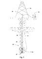
- FIG. 1 is a cross-sectional diagram of an embodiment of a downhole tool string.
- FIG. 2 is a perspective diagram of an embodiment of an inductive resistivity tool.
- FIG. 3 is a cross-sectional diagram of an embodiment of a transceiver in an inductive resistivity tool.
- FIG. 4 is a cross-sectional diagram of an embodiment of a coil tap disposed in a radial recess
- FIG. 5 is an embodiment of a graph of power verses frequency.
- FIG. 6 is an electrical schematic of an embodiment of a switch controlling the connection between a power source and an embodiment of a coil.
- FIG. 7 is an electrical schematic of another embodiment of a switch controlling the connection between a power source and an embodiment of a coil comprising a plurality of coil turn sets.
- FIG. 8 is a perspective diagram of an embodiment of a switch box controlling the connection between a power source and an embodiment of a coil.
- a downhole tool string 31 may be suspended by a derrick 32 .
- the tool string may comprise one or more downhole components 36 , linked together in a tool string 31 and in communication with surface equipment 33 through a downhole network. Having a network in the tool string 31 may enable high-speed communication between each device connected to it and facilitate the transmission and receipt of data between sensors, energy sources, and energy receivers.
- the tool string 31 or surface equipment 33 may comprise an energy source or multiple energy sources.
- the energy source may transmit electrical current to one or more downhole components 36 on the bottom hole assembly 37 or along the tool string 31 .
- one or more downhole component 36 may comprise sensors. These sensors may sense gamma rays, radioactive energy, resistivity, torque, pressure, or other drilling dynamics measurements or combinations thereof from the formation being drilled. Any combination of downhole components 36 in a tool string 31 may be compatible with the present invention.
- Data may be transmitted along the tool string 31 through techniques known in the art.
- a preferred method of downhole data transmission using inductive couplers disposed in tool joints is disclosed in the U.S. Pat. No. 6,670,880 to Hall, et al, which is herein incorporated by reference for all it discloses.
- An alternate data transmission path may comprise direct electrical contacts in tool joints such as in the system disclosed in U.S. Pat. No. 6,688,396 to Floerke, et al., which is herein incorporated by reference for all that it discloses.
- Another data transmission system that may also be adapted for use with the present invention is disclosed in U.S. Pat. No.
- alternative forms of telemetry may be used to communicate with the downhole components 36 , such as telemetry systems that communicate through the drilling mud or through the earth. Such telemetry systems may use electromagnetic or acoustic waves.
- the alternative forms of telemetry may be the primary telemetry system for communication with the tool string 31 or they may be back-up systems designed to maintain some communication if the primary telemetry system fails.
- a data swivel 34 or a wireless top-hole data connection may facilitate the transfer of data between components 36 of the rotatable tool string 31 and the stationary surface equipment, such as a control module 33 .
- the downhole tool string 31 is a drill string. In other embodiments the downhole tool string 31 is part of a production well. In the present embodiment, an embodiment of a resistivity tool 35 in accordance with the present invention is shown producing a magnetic field 30 and projecting the magnetic field 30 through the formation 40 .
- Control equipment may be in communication with the downhole tool string components 36 through an electrically conductive medium.
- a coaxial cable, wire, twisted pair of wires or combinations thereof may travel from the surface to at least one downhole tool string component.
- the medium may be in inductive or electrical communication with each other through couplers positioned so as to allow signal transmission across the connection of the downhole component and the tool string.
- the couplers may be disposed within recesses in either a primary or secondary shoulder of the connection or they may be disposed within inserts positioned within the bores of the drill bit assembly and the downhole tool string component.
- the control equipment may then change drilling parameters according to the data received to optimize drilling efficiency. Operation of the drill string 31 may include the ability to steer the direction of drilling based on the data.
- an embodiment of an inductive resistivity tool 201 is shown as part of a downhole drill string 31 .
- the resistivity tool 201 is shown intermediate first and second tool joints 202 , 203 .
- a magnetic field 30 is shown being produced by two transmitting transceivers 204 , and being received by three receiving transceivers 205 .
- the magnetic field 30 is induced into the formation, which then in turn induces the receivers 205 .
- the resistivity of the formation may be determined.
- resistivity measurements may be used to determine the petroleum potential of a formation during the drilling process.
- a sleeve 206 may be disposed around the components of the resistivity tool 201 to protect them from mud and/or debris.
- FIG. 3 a cross sectional view of an embodiment of a portion of a resistivity tool 201 is shown covered with a protective sleeve 206 .
- the tool string component has a tubular wall 301 surrounding a central bore through which drilling mud may be transferred.
- the tubular wall 301 comprises an annular radial recess 304 formed in its outer diameter 303 .
- a coil 305 is placed within the radial recess 304 and transceives induction signals outward from the tubular wall 301 when it is carrying an electrical current.
- a plurality of radial recesses 304 may be disposed in the tubular wall 301 , each recess 304 comprising at least one coil 305 .
- each coil 305 may be selectively energized.
- each coil has an inherent optimal frequency at which it resonates, which may or may not be ideal for the particular formation through which it is drilling. Thus it may be advantageous to change the optimal frequencies of the coils to be more compatible with the formation through which they are drilling.
- each coil 305 may be disposed immediately adjacent to at least one actuator 407 , which may change the electrical characteristics of the coil (and thus the optimal frequency) by connecting and disconnecting an electrically conductive element to the coil.
- a plurality of actuators may be individually triggered.
- the trigger may result from a control signal sent from a control module (located downhole or at the surface).
- a single control signal may result in triggering two or more different actuators, each for a different coil 305 , or in triggering one actuator that alters two or more different coils 305 .
- a signal line 410 may supply power to the actuator 407 and/or may carry the control signal that may trigger the actuator 407 .
- the coils 305 may be disposed within a trough of ferrite or other magnetically conducting material which is believed to focus and amplify the power of the induced signal.
- a flexible assembly of ferrite segments is formed in the shape of a ring. Flexible rings 802 may be advantageous for ease of production and assembly of the resistivity tool 201 , as well as for durability in harsh downhole conditions.
- the radial recess 304 may comprise at least two flexible rings tilted at different angles.
- the flexible ring may comprise a material selected from the group consisting of soft iron, ferrite, a nickel alloy, a silicon iron alloy, a cobalt iron alloy, a mu-metal, a laminated mu-metal, barium, strontium, carbonate, samarium, cobalt, neodymium, boron, a metal oxide, ceramics, cermets, ceramic composites, rare earth metals, an aerogel composite, polymers, organic materials, thermoset polymers, vinyl, a synthetic binder, thermoplastic polymers, an epoxy, natural rubber, fiberglass, carbon fiber composite, polyurethane, silicon, a fluorinated polymer, grease, polytetrafluoroethylene, a perfluroroalkoxy compound, resin, potting material, and combinations thereof.
- a cross-sectional diagram of an embodiment of a coil 305 is shown disposed in a radial recess 304 .
- a coil 305 may comprise between 1 and 15 coil turns 406 .
- the coil 305 may comprise an electrically insulating coating 401 and the coating may comprise one or more openings 402 adapted to allow electrical contact between the coil 305 and an electrically conductive element.
- the coil tap 403 comprises a first wire 404 and a second wires 405 . Each wire 404 , 405 is connected to a different coil turn 408 .
- the wires are connected to a switch, such as a rely or a solid state switch.
- a switch such as a rely or a solid state switch.
- the switch When the switch is activated it is believed to create an electrical shortcut between the coil turns 408 , thereby electrically bypassing any coil turns 406 between the two tapped turns 408 . It is believed that by electrically bypassing the coil turns 406 intermediate the two tapped turns 408 that the effective inductance of the coil 305 is altered, thereby altering the optimal signal frequency of the coil.
- Open space around the coil 305 , ring 802 , and the radial recess 304 may be filled with a potting material 804 .
- the potting material may comprise a material selected from the group consisting of polymers, organic materials, thermoset polymers, vinyl, an aerogel composite, a synthetic binder, thermoplastic polymers, an epoxy, natural rubber, fiberglass, carbon fiber composite, polyurethane, silicon, a fluorinated polymer, grease, polytetrafluoroethylene, a perfluroroalkoxy compound, resin, soft iron, ferrite, a nickel alloy, a silicon iron alloy, a cobalt iron alloy, a mu-metal, a laminated mu-metal, barium, strontium, carbonate, samarium, cobalt, neodymium, boron, a metal oxide, ceramics, cermets, ceramic composites, rare earth metals, and combinations thereof.
- FIG. 5 discloses a graph 411 of power verses frequency for a single coil 305 which is shielded in a ferrite trough carrying electric current.
- the graph shows a coil which resonates optimally at a frequency A as well as showing the same coil resonating at a frequency B while a coil tap is applied.
- the frequency at which a power maximum occurs may also be referred to as the optimal signal frequency of the coil. It is believed that as the number of current carrying coil turns 406 in a coil 305 increases, that the optimal signal frequency of the coil decreases.
- a single coil 305 which may be manipulated may perform at multiple optimal signal frequencies. The desirable optimal signal frequency of the coil 305 may be selected by changing the number of current carrying coil turns 406 in the coil 305 .
- the graph 411 shows two optimal signal frequencies, many other numbers of optimal signal frequencies are compatible with the current invention.
- an electrically conductive element may comprise at least one conductive wire, electrically conductive stub, capacitor, inductor, resister, transformer, varicap diode, or combinations thereof.
- an actuator may comprise at least one spring, solenoid, transistor, capacitor, varicap diode, inductor, resister, bypass capacitor, decoupling capacitor, multiplexer, or combinations thereof.
- switches may be selected from the group consisting of physical switches, electrical switches, toggle switches, rocker switches, biased switches, trembler switches, pneumatic switches, reed switches, microswitches, centrifugal switches, Hall effect switches, and combinations thereof.
- a plurality of coils 305 may be disposed in the same radial recess 304 .
- an electrical schematic 700 depicts an embodiment of a coil 305 connected to a power source 701 by a switch 702 .
- the depicted embodiment of a switch comprises a first position 703 and a second position 704 .
- current originating in the power source 701 travels through the switch 702 to a first end 705 of the coil. From the first end 705 the current travels through the coil turns 406 to the second end 706 . From the second end 706 the current may travel to another component and/or to an electrical ground 707 .
- the switch 702 is at its second position 704 the current bypasses the first end 705 and enters the coil at an intermediate junction 708 .
- the current may flow to the second end 706 through the remaining coil turns 406 , and thence to another component and/or to the ground 707 .
- the switch 702 in second position 704 breaks the electrical circuit between the first end 705 and the power source 701 , a substantial amount of current are believed to bypass the coil turns 406 between the intermediate junction 708 and the first end 705 in favor of traveling directly to the second end 706 and towards the ground 707 .
- the switch 702 between first and second positions 703 , 704 the number of coil turns 406 through which current travels is changed, thereby changing the optimal signal frequency of the coil.
- a signal alteration component 709 such as a voltage control oscillator (VCO) may be disposed between the power source 701 and the switch 702 .
- VCO voltage control oscillator
- the VCO is permanently attached to the first end 705 of the coil and when the switch moves to the second position, the first portion of the coil may be bypassed to ground.
- the signal alteration component 709 may allow for selection of specific characteristics of the electrical current that will travel through the coil 305 .
- Signal alterations may tailor the current for the specified inductance of the coil 305 .
- a single inductance value of a coil 305 may be compatible with multiple combinations of signal characteristics, and each combination of characteristics may be advantageous in specific applications and circumstances.
- a triggering signal may be sent to the switch 702 and thereby change the switch 702 between first and second positions 703 , 704 . The same or a different signal may result in the selection of signal characteristics by the signal alteration component 709 .
- an electrical schematic 900 of another embodiment of a coil 305 is disclosed in which the coil 305 comprises a plurality of coil turn sets 901 , 902 .
- first and second coil turn sets 901 , 902 are connected to a plurality of AC signal sources 750 by the means of a switch 702 .
- the electrically conductive element comprises first and second switches 903 , 904 , which act concurrently with one another.
- both coil turn sets 901 , 902 may be energized at once to obtain a third inductance and optimal signal frequency.
- two coil turn sets 901 , 902 are shown in the present embodiment, any number of coil turn sets may be consistent with the present invention.
- An embodiment of a signal alteration component 709 is disclosed disposed between both AC signal sources 750 and both switches 903 , 904 .
- a multiplexer is disclosed as a signal alteration component 709 .
- specific embodiments of signal alteration components 709 have been disclosed, other signal alteration components may be consistent with the present invention.
- the coil turn sets 901 and 902 may be in the same trough or in different troughs.
- FIG. 8 a perspective diagram discloses a coil 305 disposed in a flexible ring 802 inside a radial recess 304 .
- a plurality of coil taps 403 are shown connected to a plurality of coil turns 406 .
- Each coil tap 403 connects to at least one coil turn 406 and to a central switch box 1001 .
- the central switch box 1001 comprises a plurality of switches 702 adapted to allow individual selection of which coil turns 406 to include and exclude from the electric current flow.
- a signal line 410 may trigger the selection of which circuits to open or close inside the switch box 1001 , thereby selecting the number of coil turns 406 through which current may flow. This embodiment is believed to allow a great deal of flexibility in changing the optimal signal frequency of the coil 305 .
Abstract
Description
Claims (20)
Priority Applications (11)
| Application Number | Priority Date | Filing Date | Title |
|---|---|---|---|
| US11/687,891 US7301429B1 (en) | 2007-02-19 | 2007-03-19 | Multiple frequency inductive resistivity device |
| US12/341,872 US7888940B2 (en) | 2007-02-19 | 2008-12-22 | Induction resistivity cover |
| US12/341,771 US7898259B2 (en) | 2007-02-19 | 2008-12-22 | Downhole induction resistivity tool |
| US12/341,817 US7994791B2 (en) | 2007-02-19 | 2008-12-22 | Resistivity receiver spacing |
| US12/341,843 US8299795B2 (en) | 2007-02-19 | 2008-12-22 | Independently excitable resistivity units |
| US12/405,880 US8198898B2 (en) | 2007-02-19 | 2009-03-17 | Downhole removable cage with circumferentially disposed instruments |
| US12/473,416 US20090230969A1 (en) | 2007-02-19 | 2009-05-28 | Downhole Acoustic Receiver with Canceling Element |
| US12/550,501 US8395388B2 (en) | 2007-02-19 | 2009-08-31 | Circumferentially spaced magnetic field generating devices |
| US12/614,635 US8436618B2 (en) | 2007-02-19 | 2009-11-09 | Magnetic field deflector in an induction resistivity tool |
| US12/846,348 US20100295547A1 (en) | 2007-02-19 | 2010-07-29 | Downhole Resistivity Receiver with Canceling Element |
| US12/940,828 US8030936B2 (en) | 2007-02-19 | 2010-11-05 | Logging tool with independently energizable transmitters |
Applications Claiming Priority (2)
| Application Number | Priority Date | Filing Date | Title |
|---|---|---|---|
| US11/676,494 US7265649B1 (en) | 2007-02-19 | 2007-02-19 | Flexible inductive resistivity device |
| US11/687,891 US7301429B1 (en) | 2007-02-19 | 2007-03-19 | Multiple frequency inductive resistivity device |
Related Parent Applications (1)
| Application Number | Title | Priority Date | Filing Date |
|---|---|---|---|
| US11/676,494 Continuation-In-Part US7265649B1 (en) | 2007-02-19 | 2007-02-19 | Flexible inductive resistivity device |
Related Child Applications (4)
| Application Number | Title | Priority Date | Filing Date |
|---|---|---|---|
| US11/676,494 Continuation-In-Part US7265649B1 (en) | 2007-02-19 | 2007-02-19 | Flexible inductive resistivity device |
| US11/776,447 Continuation-In-Part US7598742B2 (en) | 2007-02-19 | 2007-07-11 | Externally guided and directed field induction resistivity tool |
| US12/341,771 Continuation-In-Part US7898259B2 (en) | 2007-02-19 | 2008-12-22 | Downhole induction resistivity tool |
| US12/405,880 Continuation-In-Part US8198898B2 (en) | 2007-02-19 | 2009-03-17 | Downhole removable cage with circumferentially disposed instruments |
Publications (1)
| Publication Number | Publication Date |
|---|---|
| US7301429B1 true US7301429B1 (en) | 2007-11-27 |
Family
ID=38456914
Family Applications (2)
| Application Number | Title | Priority Date | Filing Date |
|---|---|---|---|
| US11/676,494 Expired - Fee Related US7265649B1 (en) | 2007-02-19 | 2007-02-19 | Flexible inductive resistivity device |
| US11/687,891 Expired - Fee Related US7301429B1 (en) | 2007-02-19 | 2007-03-19 | Multiple frequency inductive resistivity device |
Family Applications Before (1)
| Application Number | Title | Priority Date | Filing Date |
|---|---|---|---|
| US11/676,494 Expired - Fee Related US7265649B1 (en) | 2007-02-19 | 2007-02-19 | Flexible inductive resistivity device |
Country Status (1)
| Country | Link |
|---|---|
| US (2) | US7265649B1 (en) |
Cited By (20)
| Publication number | Priority date | Publication date | Assignee | Title |
|---|---|---|---|---|
| US20080236837A1 (en) * | 2007-03-30 | 2008-10-02 | Schlumberger Technology Corporation | Communicating measurement data from a well |
| US20080265892A1 (en) * | 2007-04-27 | 2008-10-30 | Snyder Harold L | Externally Guided and Directed Field Induction Resistivity Tool |
| US20090160445A1 (en) * | 2007-02-19 | 2009-06-25 | Hall David R | Resistivity Reference Receiver |
| US20090266609A1 (en) * | 2008-04-24 | 2009-10-29 | Hall David R | Downhole sample rate system |
| US20100283468A1 (en) * | 2008-06-27 | 2010-11-11 | John Signorelli | Remotely located tuning circuits for multi-frequency, multi-puropse induction antennae in downhole tools |
| US8198898B2 (en) | 2007-02-19 | 2012-06-12 | Schlumberger Technology Corporation | Downhole removable cage with circumferentially disposed instruments |
| US8395388B2 (en) | 2007-02-19 | 2013-03-12 | Schlumberger Technology Corporation | Circumferentially spaced magnetic field generating devices |
| US8436618B2 (en) | 2007-02-19 | 2013-05-07 | Schlumberger Technology Corporation | Magnetic field deflector in an induction resistivity tool |
| WO2013148830A1 (en) * | 2012-03-29 | 2013-10-03 | Schlumberger Canada Limited | Removable modular antenna assembly for downhole applications |
| US8836335B2 (en) | 2012-06-13 | 2014-09-16 | Baker Hughes Incorporated | Multi-capacitor system for electromagnetic logging tool |
| US20150302982A1 (en) * | 2013-09-03 | 2015-10-22 | U.S. Army Research Laboratory Attn: Rdrl-Loc-I | Mems tunable inductor |
| US20170235012A1 (en) * | 2016-02-17 | 2017-08-17 | Baker Hughes Incorporated | Method and apparatus for estimating formation properties using transient electromagnetic measurements while drilling |
| WO2018031766A1 (en) * | 2016-08-12 | 2018-02-15 | Baker Hughes, A Ge Company, Llc | Frequency modulation for magnetic pressure pulse tool |
| US10024996B2 (en) | 2015-10-12 | 2018-07-17 | Halliburton Energy Services, Inc. | Collocated coil antennas incorporating a symmetric soft magnetic band |
| US20180217288A1 (en) * | 2014-08-06 | 2018-08-02 | Cgg Services Sas | Systems and methods for active cancellation of transient signals and dynamic loop configuration |
| US10156655B2 (en) | 2016-03-08 | 2018-12-18 | Baker Hughes, A Ge Company, Llc | Method and apparatus for measurement of pipe signals for downhole transient electromagnetic processing |
| US10162076B2 (en) | 2016-03-14 | 2018-12-25 | Baker Hughes, A Ge Company, Llc | Method and apparatus for correction of transient electromagnetic signals to remove a pipe response |
| US10261210B2 (en) | 2016-03-09 | 2019-04-16 | Baker Hughes, A Ge Company, Llc | Method and apparatus for active suppression of pipe signals in transient electromagnetic measurements |
| US10626705B2 (en) | 2018-02-09 | 2020-04-21 | Baer Hughes, A Ge Company, Llc | Magnetic pulse actuation arrangement having layer and method |
| US10801283B2 (en) | 2016-08-12 | 2020-10-13 | Baker Hughes, A Ge Company, Llc | Magnetic pulse actuation arrangement for downhole tools and method |
Families Citing this family (11)
| Publication number | Priority date | Publication date | Assignee | Title |
|---|---|---|---|---|
| US20090033516A1 (en) * | 2007-08-02 | 2009-02-05 | Schlumberger Technology Corporation | Instrumented wellbore tools and methods |
| US20090120689A1 (en) * | 2007-11-12 | 2009-05-14 | Baker Hughes Incorporated | Apparatus and method for communicating information between a wellbore and surface |
| DE102008021773B4 (en) * | 2008-04-30 | 2010-04-15 | Hottinger Baldwin Messtechnik Gmbh | Rotor antenna ring |
| WO2011043851A1 (en) | 2009-10-05 | 2011-04-14 | Halliburton Energy Services, Inc. | Deep evaluation of resistive anomalies in borehole environments |
| US8860416B2 (en) | 2009-10-05 | 2014-10-14 | Halliburton Energy Services, Inc. | Downhole sensing in borehole environments |
| CA2802981A1 (en) | 2010-09-16 | 2011-03-22 | Kwokshan Kwong | Combined sonic/pulsed neutron cased hole logging tool |
| US8797035B2 (en) * | 2011-11-09 | 2014-08-05 | Halliburton Energy Services, Inc. | Apparatus and methods for monitoring a core during coring operations |
| US8854044B2 (en) | 2011-11-09 | 2014-10-07 | Haliburton Energy Services, Inc. | Instrumented core barrels and methods of monitoring a core while the core is being cut |
| GB2538517A (en) * | 2015-05-19 | 2016-11-23 | I2I Pipelines Ltd | Improved pipe pig |
| CN111509354B (en) * | 2020-04-26 | 2021-09-10 | 中国海洋石油集团有限公司 | Wireless signal transmission antenna of while-drilling instrument |
| US11814955B2 (en) * | 2022-07-18 | 2023-11-14 | Joe Fox | Tool string telemetry network |
Citations (40)
| Publication number | Priority date | Publication date | Assignee | Title |
|---|---|---|---|---|
| US4278556A (en) | 1978-05-19 | 1981-07-14 | Tdk Electronics Co., Ltd. | Process for producing flexible magnets |
| US4302722A (en) * | 1979-06-15 | 1981-11-24 | Schlumberger Technology Corporation | Induction logging utilizing resistive and reactive induced signal components to determine conductivity and coefficient of anisotropy |
| US4536714A (en) | 1982-04-16 | 1985-08-20 | Schlumberger Technology Corporation | Shields for antennas of borehole logging devices |
| US4766384A (en) | 1986-06-20 | 1988-08-23 | Schlumberger Technology Corp. | Well logging apparatus for determining dip, azimuth, and invaded zone conductivity |
| US4808929A (en) * | 1983-11-14 | 1989-02-28 | Schlumberger Technology Corporation | Shielded induction sensor for well logging |
| US4839644A (en) * | 1987-06-10 | 1989-06-13 | Schlumberger Technology Corp. | System and method for communicating signals in a cased borehole having tubing |
| US4881988A (en) | 1987-11-16 | 1989-11-21 | Rjf International Corporation | Novel flexible magnet for use in small dc motors |
| US5138263A (en) | 1991-01-16 | 1992-08-11 | Teleco Oilfield Services Inc. | Electromagnetic formation evaluation tool |
| US5491488A (en) | 1992-06-11 | 1996-02-13 | Baker Hughes Incorporated | Electromagnetic propagation tool using magnetic dipole antennas |
| US5530358A (en) | 1994-01-25 | 1996-06-25 | Baker Hughes, Incorporated | Method and apparatus for measurement-while-drilling utilizing improved antennas |
| US6114972A (en) | 1998-01-20 | 2000-09-05 | Halliburton Energy Services, Inc. | Electromagnetic resistivity tool and method for use of same |
| US6191586B1 (en) | 1998-06-10 | 2001-02-20 | Dresser Industries, Inc. | Method and apparatus for azimuthal electromagnetic well logging using shielded antennas |
| US6218842B1 (en) | 1999-08-04 | 2001-04-17 | Halliburton Energy Services, Inc. | Multi-frequency electromagnetic wave resistivity tool with improved calibration measurement |
| US6259030B1 (en) | 1998-03-12 | 2001-07-10 | Sumitomo Wiring Systems, Ltd. | Electrical cables adapted for high voltage applications |
| US6297639B1 (en) | 1999-12-01 | 2001-10-02 | Schlumberger Technology Corporation | Method and apparatus for directional well logging with a shield having sloped slots |
| US6344746B1 (en) | 1999-12-03 | 2002-02-05 | Baker Hughes Incorporated | Method for processing the lapse measurements |
| US6359438B1 (en) | 2000-01-28 | 2002-03-19 | Halliburton Energy Services, Inc. | Multi-depth focused resistivity imaging tool for logging while drilling applications |
| US6538447B2 (en) | 2000-12-13 | 2003-03-25 | Halliburton Energy Services, Inc. | Compensated multi-mode elctromagnetic wave resistivity tool |
| US6577129B1 (en) | 2002-01-19 | 2003-06-10 | Precision Drilling Technology Services Group Inc. | Well logging system for determining directional resistivity using multiple transmitter-receiver groups focused with magnetic reluctance material |
| US6630831B2 (en) | 2000-09-02 | 2003-10-07 | Em-Tech Sensors Llc | Measurements of electrical properties through non magneticially permeable metals using directed magnetic beams and magnetic lenses |
| US6646441B2 (en) | 2002-01-19 | 2003-11-11 | Precision Drilling Technology Services Group Inc. | Well logging system for determining resistivity using multiple transmitter-receiver groups operating at three frequencies |
| US6677756B2 (en) | 2001-08-03 | 2004-01-13 | Baker Hughes Incorporated | Multi-component induction instrument |
| US6703837B1 (en) | 2000-09-15 | 2004-03-09 | Precision Drilling Technology Services Group, Inc. | Wellbore resistivity tool with simultaneous multiple frequencies |
| US20040113626A1 (en) | 2002-09-06 | 2004-06-17 | Baker Hughes, Inc. | Method and apparatus for directional resistivity measurement while drilling |
| US6765385B2 (en) | 2001-11-13 | 2004-07-20 | Weatherford/Lamb, Inc. | Method, apparatus and system for compensating the effects of borehole variations |
| US6768700B2 (en) * | 2001-02-22 | 2004-07-27 | Schlumberger Technology Corporation | Method and apparatus for communications in a wellbore |
| US6777940B2 (en) | 2002-11-08 | 2004-08-17 | Ultima Labs, Inc. | Apparatus and method for resistivity well logging |
| US6810331B2 (en) | 2002-09-25 | 2004-10-26 | Halliburton Energy Services, Inc. | Fixed-depth of investigation log for multi-spacing multi-frequency LWD resistivity tools |
| US6814162B2 (en) | 2002-08-09 | 2004-11-09 | Smith International, Inc. | One cone bit with interchangeable cutting structures, a box-end connection, and integral sensory devices |
| US6849195B2 (en) | 2003-04-03 | 2005-02-01 | Delphi Technologies, Inc. | Composites with large magnetostriction |
| US6900640B2 (en) | 2001-08-03 | 2005-05-31 | Baker Hughes Incorporated | Method and apparatus for a multi-component induction instrument measuring system for geosteering and formation resistivity data interpretation in horizontal, vertical and deviated wells |
| US6913095B2 (en) | 2002-05-15 | 2005-07-05 | Baker Hughes Incorporated | Closed loop drilling assembly with electronics outside a non-rotating sleeve |
| US6915701B1 (en) | 2003-07-18 | 2005-07-12 | Cleveland Medical Devices Inc. | Composite material for a sensor for measuring shear forces |
| US7031839B2 (en) | 2002-11-15 | 2006-04-18 | Baker Hughes Incorporated | Multi-frequency focusing for MWD resistivity tools |
| US7040003B2 (en) | 2000-07-19 | 2006-05-09 | Intelliserv, Inc. | Inductive coupler for downhole components and method for making same |
| US7064676B2 (en) | 2000-07-19 | 2006-06-20 | Intelliserv, Inc. | Downhole data transmission system |
| US7091810B2 (en) | 2004-06-28 | 2006-08-15 | Intelliserv, Inc. | Element of an inductive coupler |
| US7095232B2 (en) * | 2003-05-29 | 2006-08-22 | Schlumberger Technology Corporation | Determination of borehole geometry inside cased wells with crosswell electromagnetics |
| US20060197629A1 (en) | 2005-03-05 | 2006-09-07 | Erich Pivit | 3DB coupler |
| US20060208383A1 (en) | 2005-03-17 | 2006-09-21 | Thomas Aisenbrey | Low cost magnets and magnetic devices manufactured from ferromagnetic conductively doped resin-based materials |
Family Cites Families (2)
| Publication number | Priority date | Publication date | Assignee | Title |
|---|---|---|---|---|
| US4563714A (en) | 1984-03-19 | 1986-01-07 | Tokyo Shibaura Denki Kabushiki Kaisha | Method and device for controlling the tracking |
| US6285014B1 (en) * | 2000-04-28 | 2001-09-04 | Neo Ppg International, Ltd. | Downhole induction heating tool for enhanced oil recovery |
-
2007
- 2007-02-19 US US11/676,494 patent/US7265649B1/en not_active Expired - Fee Related
- 2007-03-19 US US11/687,891 patent/US7301429B1/en not_active Expired - Fee Related
Patent Citations (42)
| Publication number | Priority date | Publication date | Assignee | Title |
|---|---|---|---|---|
| US4278556A (en) | 1978-05-19 | 1981-07-14 | Tdk Electronics Co., Ltd. | Process for producing flexible magnets |
| US4302722A (en) * | 1979-06-15 | 1981-11-24 | Schlumberger Technology Corporation | Induction logging utilizing resistive and reactive induced signal components to determine conductivity and coefficient of anisotropy |
| US4536714A (en) | 1982-04-16 | 1985-08-20 | Schlumberger Technology Corporation | Shields for antennas of borehole logging devices |
| US4808929A (en) * | 1983-11-14 | 1989-02-28 | Schlumberger Technology Corporation | Shielded induction sensor for well logging |
| US4766384A (en) | 1986-06-20 | 1988-08-23 | Schlumberger Technology Corp. | Well logging apparatus for determining dip, azimuth, and invaded zone conductivity |
| US4839644A (en) * | 1987-06-10 | 1989-06-13 | Schlumberger Technology Corp. | System and method for communicating signals in a cased borehole having tubing |
| US4881988A (en) | 1987-11-16 | 1989-11-21 | Rjf International Corporation | Novel flexible magnet for use in small dc motors |
| US5138263A (en) | 1991-01-16 | 1992-08-11 | Teleco Oilfield Services Inc. | Electromagnetic formation evaluation tool |
| US5491488A (en) | 1992-06-11 | 1996-02-13 | Baker Hughes Incorporated | Electromagnetic propagation tool using magnetic dipole antennas |
| US5530358A (en) | 1994-01-25 | 1996-06-25 | Baker Hughes, Incorporated | Method and apparatus for measurement-while-drilling utilizing improved antennas |
| US6114972A (en) | 1998-01-20 | 2000-09-05 | Halliburton Energy Services, Inc. | Electromagnetic resistivity tool and method for use of same |
| US6259030B1 (en) | 1998-03-12 | 2001-07-10 | Sumitomo Wiring Systems, Ltd. | Electrical cables adapted for high voltage applications |
| US6191586B1 (en) | 1998-06-10 | 2001-02-20 | Dresser Industries, Inc. | Method and apparatus for azimuthal electromagnetic well logging using shielded antennas |
| US6218842B1 (en) | 1999-08-04 | 2001-04-17 | Halliburton Energy Services, Inc. | Multi-frequency electromagnetic wave resistivity tool with improved calibration measurement |
| US6297639B1 (en) | 1999-12-01 | 2001-10-02 | Schlumberger Technology Corporation | Method and apparatus for directional well logging with a shield having sloped slots |
| US6344746B1 (en) | 1999-12-03 | 2002-02-05 | Baker Hughes Incorporated | Method for processing the lapse measurements |
| US6359438B1 (en) | 2000-01-28 | 2002-03-19 | Halliburton Energy Services, Inc. | Multi-depth focused resistivity imaging tool for logging while drilling applications |
| US7116199B2 (en) | 2000-07-19 | 2006-10-03 | Intelliserv, Inc. | Inductive coupler for downhole components and method for making same |
| US20060158296A1 (en) | 2000-07-19 | 2006-07-20 | Hall David R | Inductive Coupler for Downhole Components and Method for Making Same |
| US7064676B2 (en) | 2000-07-19 | 2006-06-20 | Intelliserv, Inc. | Downhole data transmission system |
| US7040003B2 (en) | 2000-07-19 | 2006-05-09 | Intelliserv, Inc. | Inductive coupler for downhole components and method for making same |
| US6630831B2 (en) | 2000-09-02 | 2003-10-07 | Em-Tech Sensors Llc | Measurements of electrical properties through non magneticially permeable metals using directed magnetic beams and magnetic lenses |
| US6703837B1 (en) | 2000-09-15 | 2004-03-09 | Precision Drilling Technology Services Group, Inc. | Wellbore resistivity tool with simultaneous multiple frequencies |
| US6538447B2 (en) | 2000-12-13 | 2003-03-25 | Halliburton Energy Services, Inc. | Compensated multi-mode elctromagnetic wave resistivity tool |
| US6768700B2 (en) * | 2001-02-22 | 2004-07-27 | Schlumberger Technology Corporation | Method and apparatus for communications in a wellbore |
| US6900640B2 (en) | 2001-08-03 | 2005-05-31 | Baker Hughes Incorporated | Method and apparatus for a multi-component induction instrument measuring system for geosteering and formation resistivity data interpretation in horizontal, vertical and deviated wells |
| US6677756B2 (en) | 2001-08-03 | 2004-01-13 | Baker Hughes Incorporated | Multi-component induction instrument |
| US6765385B2 (en) | 2001-11-13 | 2004-07-20 | Weatherford/Lamb, Inc. | Method, apparatus and system for compensating the effects of borehole variations |
| US6577129B1 (en) | 2002-01-19 | 2003-06-10 | Precision Drilling Technology Services Group Inc. | Well logging system for determining directional resistivity using multiple transmitter-receiver groups focused with magnetic reluctance material |
| US6646441B2 (en) | 2002-01-19 | 2003-11-11 | Precision Drilling Technology Services Group Inc. | Well logging system for determining resistivity using multiple transmitter-receiver groups operating at three frequencies |
| US6913095B2 (en) | 2002-05-15 | 2005-07-05 | Baker Hughes Incorporated | Closed loop drilling assembly with electronics outside a non-rotating sleeve |
| US6814162B2 (en) | 2002-08-09 | 2004-11-09 | Smith International, Inc. | One cone bit with interchangeable cutting structures, a box-end connection, and integral sensory devices |
| US20040113626A1 (en) | 2002-09-06 | 2004-06-17 | Baker Hughes, Inc. | Method and apparatus for directional resistivity measurement while drilling |
| US6810331B2 (en) | 2002-09-25 | 2004-10-26 | Halliburton Energy Services, Inc. | Fixed-depth of investigation log for multi-spacing multi-frequency LWD resistivity tools |
| US6777940B2 (en) | 2002-11-08 | 2004-08-17 | Ultima Labs, Inc. | Apparatus and method for resistivity well logging |
| US7031839B2 (en) | 2002-11-15 | 2006-04-18 | Baker Hughes Incorporated | Multi-frequency focusing for MWD resistivity tools |
| US6849195B2 (en) | 2003-04-03 | 2005-02-01 | Delphi Technologies, Inc. | Composites with large magnetostriction |
| US7095232B2 (en) * | 2003-05-29 | 2006-08-22 | Schlumberger Technology Corporation | Determination of borehole geometry inside cased wells with crosswell electromagnetics |
| US6915701B1 (en) | 2003-07-18 | 2005-07-12 | Cleveland Medical Devices Inc. | Composite material for a sensor for measuring shear forces |
| US7091810B2 (en) | 2004-06-28 | 2006-08-15 | Intelliserv, Inc. | Element of an inductive coupler |
| US20060197629A1 (en) | 2005-03-05 | 2006-09-07 | Erich Pivit | 3DB coupler |
| US20060208383A1 (en) | 2005-03-17 | 2006-09-21 | Thomas Aisenbrey | Low cost magnets and magnetic devices manufactured from ferromagnetic conductively doped resin-based materials |
Cited By (44)
| Publication number | Priority date | Publication date | Assignee | Title |
|---|---|---|---|---|
| US7888940B2 (en) | 2007-02-19 | 2011-02-15 | Schlumberger Technology Corporation | Induction resistivity cover |
| US7994791B2 (en) | 2007-02-19 | 2011-08-09 | Schlumberger Technology Corporation | Resistivity receiver spacing |
| US7898259B2 (en) | 2007-02-19 | 2011-03-01 | Schlumberger Technology Corporation | Downhole induction resistivity tool |
| US20110068797A1 (en) * | 2007-02-19 | 2011-03-24 | Schlumberger Technology Corporation | Logging tool with independently energizable transmitters |
| US20090160448A1 (en) * | 2007-02-19 | 2009-06-25 | Hall David R | Induction Resistivity Cover |
| US8198898B2 (en) | 2007-02-19 | 2012-06-12 | Schlumberger Technology Corporation | Downhole removable cage with circumferentially disposed instruments |
| US8395388B2 (en) | 2007-02-19 | 2013-03-12 | Schlumberger Technology Corporation | Circumferentially spaced magnetic field generating devices |
| US8436618B2 (en) | 2007-02-19 | 2013-05-07 | Schlumberger Technology Corporation | Magnetic field deflector in an induction resistivity tool |
| US8299795B2 (en) | 2007-02-19 | 2012-10-30 | Schlumberger Technology Corporation | Independently excitable resistivity units |
| US20090160445A1 (en) * | 2007-02-19 | 2009-06-25 | Hall David R | Resistivity Reference Receiver |
| US20090160446A1 (en) * | 2007-02-19 | 2009-06-25 | Hall David R | Resistivity Receiver Spacing |
| US8030936B2 (en) | 2007-02-19 | 2011-10-04 | Schlumberger Technology Corporation | Logging tool with independently energizable transmitters |
| US7921916B2 (en) * | 2007-03-30 | 2011-04-12 | Schlumberger Technology Corporation | Communicating measurement data from a well |
| US20080236837A1 (en) * | 2007-03-30 | 2008-10-02 | Schlumberger Technology Corporation | Communicating measurement data from a well |
| US7982463B2 (en) | 2007-04-27 | 2011-07-19 | Schlumberger Technology Corporation | Externally guided and directed field induction resistivity tool |
| US20080265892A1 (en) * | 2007-04-27 | 2008-10-30 | Snyder Harold L | Externally Guided and Directed Field Induction Resistivity Tool |
| US20100097067A1 (en) * | 2007-04-27 | 2010-04-22 | Synder Jr Harold L | Externally Guided and Directed Field Induction Resistivity Tool |
| US8072221B2 (en) | 2007-04-27 | 2011-12-06 | Schlumberger Technology Corporation | Externally guided and directed field induction resistivity tool |
| US20090266609A1 (en) * | 2008-04-24 | 2009-10-29 | Hall David R | Downhole sample rate system |
| US8061443B2 (en) | 2008-04-24 | 2011-11-22 | Schlumberger Technology Corporation | Downhole sample rate system |
| US20120032868A1 (en) * | 2008-06-27 | 2012-02-09 | Baker Hughes Incorporated | Remotely Located Tuning Circuits for Multi-Frequency, Multi-Purpose Induction Antennae in Downhole Tools |
| US20100283468A1 (en) * | 2008-06-27 | 2010-11-11 | John Signorelli | Remotely located tuning circuits for multi-frequency, multi-puropse induction antennae in downhole tools |
| US9146332B2 (en) * | 2008-06-27 | 2015-09-29 | Baker Hughes Incorporated | Remotely located tuning circuits for multi-frequency, multi-purpose induction antennae in downhole tools |
| WO2013148830A1 (en) * | 2012-03-29 | 2013-10-03 | Schlumberger Canada Limited | Removable modular antenna assembly for downhole applications |
| US9181798B2 (en) | 2012-03-29 | 2015-11-10 | Schlumberger Technology Corporation | Removable modular antenna assembly for downhole applications |
| US8836335B2 (en) | 2012-06-13 | 2014-09-16 | Baker Hughes Incorporated | Multi-capacitor system for electromagnetic logging tool |
| US20150302982A1 (en) * | 2013-09-03 | 2015-10-22 | U.S. Army Research Laboratory Attn: Rdrl-Loc-I | Mems tunable inductor |
| US9583250B2 (en) * | 2013-09-03 | 2017-02-28 | The United States Of America As Represented By The Secretary Of The Army | MEMS tunable inductor |
| US20180217288A1 (en) * | 2014-08-06 | 2018-08-02 | Cgg Services Sas | Systems and methods for active cancellation of transient signals and dynamic loop configuration |
| US10024996B2 (en) | 2015-10-12 | 2018-07-17 | Halliburton Energy Services, Inc. | Collocated coil antennas incorporating a symmetric soft magnetic band |
| US10197695B2 (en) * | 2016-02-17 | 2019-02-05 | Baker Hughes, A Ge Company, Llc | Method and apparatus for estimating formation properties using transient electromagnetic measurements while drilling |
| US20170235012A1 (en) * | 2016-02-17 | 2017-08-17 | Baker Hughes Incorporated | Method and apparatus for estimating formation properties using transient electromagnetic measurements while drilling |
| US10156655B2 (en) | 2016-03-08 | 2018-12-18 | Baker Hughes, A Ge Company, Llc | Method and apparatus for measurement of pipe signals for downhole transient electromagnetic processing |
| US10261210B2 (en) | 2016-03-09 | 2019-04-16 | Baker Hughes, A Ge Company, Llc | Method and apparatus for active suppression of pipe signals in transient electromagnetic measurements |
| US10162076B2 (en) | 2016-03-14 | 2018-12-25 | Baker Hughes, A Ge Company, Llc | Method and apparatus for correction of transient electromagnetic signals to remove a pipe response |
| WO2018031766A1 (en) * | 2016-08-12 | 2018-02-15 | Baker Hughes, A Ge Company, Llc | Frequency modulation for magnetic pressure pulse tool |
| US20180043463A1 (en) * | 2016-08-12 | 2018-02-15 | Baker Hughes Incorporated | Frequency modulation for magnetic pressure pulse tool |
| GB2568009A (en) * | 2016-08-12 | 2019-05-01 | Baker Hughes A Ge Co Llc | Frequency modulation for magnetic pressure pulse tool |
| US10596655B2 (en) | 2016-08-12 | 2020-03-24 | Baker Hughes, A Ge Company, Llc | Magnetic pulse actuation arrangement for downhole tools and method |
| US10801283B2 (en) | 2016-08-12 | 2020-10-13 | Baker Hughes, A Ge Company, Llc | Magnetic pulse actuation arrangement for downhole tools and method |
| US11014191B2 (en) * | 2016-08-12 | 2021-05-25 | Baker Hughes, A Ge Company, Llc | Frequency modulation for magnetic pressure pulse tool |
| GB2568009B (en) * | 2016-08-12 | 2021-06-16 | Baker Hughes A Ge Co Llc | Frequency modulation for magnetic pressure pulse tool |
| US11465229B2 (en) | 2016-08-12 | 2022-10-11 | Baker Hughes, LLC | Frequency modulation for magnetic pressure pulse tool |
| US10626705B2 (en) | 2018-02-09 | 2020-04-21 | Baer Hughes, A Ge Company, Llc | Magnetic pulse actuation arrangement having layer and method |
Also Published As
| Publication number | Publication date |
|---|---|
| US7265649B1 (en) | 2007-09-04 |
Similar Documents
| Publication | Publication Date | Title |
|---|---|---|
| US7301429B1 (en) | Multiple frequency inductive resistivity device | |
| US7541813B2 (en) | Externally guided and directed halbach array field induction resistivity tool | |
| US7598742B2 (en) | Externally guided and directed field induction resistivity tool | |
| US7583085B2 (en) | Downhole sensor assembly | |
| US7382273B2 (en) | Wired tool string component | |
| CA2435351C (en) | Replaceable antennas for wellbore apparatus | |
| US8130118B2 (en) | Wired tool string component | |
| US4785247A (en) | Drill stem logging with electromagnetic waves and electrostatically-shielded and inductively-coupled transmitter and receiver elements | |
| CA2363534C (en) | Shielding method and apparatus using transverse slots | |
| US8519865B2 (en) | Downhole coils | |
| US7812609B2 (en) | Antennas for deep induction array tools with increased sensitivities | |
| US8264369B2 (en) | Intelligent electrical power distribution system | |
| US7742008B2 (en) | Multipole antennae for logging-while-drilling resistivity measurements | |
| US20080012569A1 (en) | Downhole Coils | |
| CA1235179A (en) | Drill stem logging system with electomagnetic waves using electrostatically shielded transmitter and receiver elements | |
| US8847600B2 (en) | Use of autotransformer-like antennas for downhole applications | |
| US20090151926A1 (en) | Inductive Power Coupler | |
| NO321294B1 (en) | Electromagnetic downhole telemetry system and method during drilling using downhole station receiver | |
| EP0987401A2 (en) | Drill string telemetry | |
| US8436618B2 (en) | Magnetic field deflector in an induction resistivity tool | |
| AU2000265796A1 (en) | Apparatus and method for telemetry | |
| US20100295547A1 (en) | Downhole Resistivity Receiver with Canceling Element | |
| US20230014307A1 (en) | A telemetry tool joint | |
| AU9725201A (en) | Retrievable, formation resistivity tool, having a slotted collar |
Legal Events
| Date | Code | Title | Description |
|---|---|---|---|
| AS | Assignment |
Owner name: HALL, DAVID R., MR., UTAH Free format text: ASSIGNMENT OF ASSIGNORS INTEREST;ASSIGNORS:SHUMWAY, JIM, MR.;TURNER, PAULA, MS.;MILLS, JAD A., MR.;AND OTHERS;REEL/FRAME:019030/0788;SIGNING DATES FROM 20070221 TO 20070319 |
|
| STCF | Information on status: patent grant |
Free format text: PATENTED CASE |
|
| AS | Assignment |
Owner name: NOVADRILL, INC., UTAH Free format text: ASSIGNMENT OF ASSIGNORS INTEREST;ASSIGNOR:HALL, DAVID R.;REEL/FRAME:021701/0758 Effective date: 20080806 Owner name: NOVADRILL, INC.,UTAH Free format text: ASSIGNMENT OF ASSIGNORS INTEREST;ASSIGNOR:HALL, DAVID R.;REEL/FRAME:021701/0758 Effective date: 20080806 |
|
| FEPP | Fee payment procedure |
Free format text: PAT HOLDER NO LONGER CLAIMS SMALL ENTITY STATUS, ENTITY STATUS SET TO UNDISCOUNTED (ORIGINAL EVENT CODE: STOL); ENTITY STATUS OF PATENT OWNER: LARGE ENTITY |
|
| AS | Assignment |
Owner name: SCHLUMBERGER TECHNOLOGY CORPORATION,TEXAS Free format text: ASSIGNMENT OF ASSIGNORS INTEREST;ASSIGNOR:NOVADRILL, INC.;REEL/FRAME:024055/0457 Effective date: 20100121 Owner name: SCHLUMBERGER TECHNOLOGY CORPORATION, TEXAS Free format text: ASSIGNMENT OF ASSIGNORS INTEREST;ASSIGNOR:NOVADRILL, INC.;REEL/FRAME:024055/0457 Effective date: 20100121 |
|
| FEPP | Fee payment procedure |
Free format text: PAYER NUMBER DE-ASSIGNED (ORIGINAL EVENT CODE: RMPN); ENTITY STATUS OF PATENT OWNER: LARGE ENTITY Free format text: PAYOR NUMBER ASSIGNED (ORIGINAL EVENT CODE: ASPN); ENTITY STATUS OF PATENT OWNER: LARGE ENTITY |
|
| FPAY | Fee payment |
Year of fee payment: 4 |
|
| FPAY | Fee payment |
Year of fee payment: 8 |
|
| FEPP | Fee payment procedure |
Free format text: MAINTENANCE FEE REMINDER MAILED (ORIGINAL EVENT CODE: REM.); ENTITY STATUS OF PATENT OWNER: LARGE ENTITY |
|
| LAPS | Lapse for failure to pay maintenance fees |
Free format text: PATENT EXPIRED FOR FAILURE TO PAY MAINTENANCE FEES (ORIGINAL EVENT CODE: EXP.); ENTITY STATUS OF PATENT OWNER: LARGE ENTITY |
|
| STCH | Information on status: patent discontinuation |
Free format text: PATENT EXPIRED DUE TO NONPAYMENT OF MAINTENANCE FEES UNDER 37 CFR 1.362 |
|
| FP | Lapsed due to failure to pay maintenance fee |
Effective date: 20191127 |