US7289470B2 - Method and apparatus of performing handoff - Google Patents
Method and apparatus of performing handoff Download PDFInfo
- Publication number
- US7289470B2 US7289470B2 US10/268,101 US26810102A US7289470B2 US 7289470 B2 US7289470 B2 US 7289470B2 US 26810102 A US26810102 A US 26810102A US 7289470 B2 US7289470 B2 US 7289470B2
- Authority
- US
- United States
- Prior art keywords
- base station
- specific weight
- weight factor
- mobile station
- antenna specific
- Prior art date
- Legal status (The legal status is an assumption and is not a legal conclusion. Google has not performed a legal analysis and makes no representation as to the accuracy of the status listed.)
- Expired - Fee Related, expires
Links
- 238000000034 method Methods 0.000 title claims description 27
- 238000010295 mobile communication Methods 0.000 claims abstract description 7
- 230000005540 biological transmission Effects 0.000 claims description 57
- 238000010586 diagram Methods 0.000 description 13
- 238000004891 communication Methods 0.000 description 7
- 230000009977 dual effect Effects 0.000 description 3
- 230000000694 effects Effects 0.000 description 2
- 238000005562 fading Methods 0.000 description 1
- 238000013507 mapping Methods 0.000 description 1
- 238000012986 modification Methods 0.000 description 1
- 230000004048 modification Effects 0.000 description 1
Images


Classifications
-
- H—ELECTRICITY
- H04—ELECTRIC COMMUNICATION TECHNIQUE
- H04W—WIRELESS COMMUNICATION NETWORKS
- H04W36/00—Hand-off or reselection arrangements
- H04W36/16—Performing reselection for specific purposes
- H04W36/18—Performing reselection for specific purposes for allowing seamless reselection, e.g. soft reselection
-
- H—ELECTRICITY
- H04—ELECTRIC COMMUNICATION TECHNIQUE
- H04W—WIRELESS COMMUNICATION NETWORKS
- H04W36/00—Hand-off or reselection arrangements
- H04W36/24—Reselection being triggered by specific parameters
- H04W36/30—Reselection being triggered by specific parameters by measured or perceived connection quality data
- H04W36/304—Reselection being triggered by specific parameters by measured or perceived connection quality data due to measured or perceived resources with higher communication quality
-
- H—ELECTRICITY
- H04—ELECTRIC COMMUNICATION TECHNIQUE
- H04B—TRANSMISSION
- H04B7/00—Radio transmission systems, i.e. using radiation field
- H04B7/02—Diversity systems; Multi-antenna system, i.e. transmission or reception using multiple antennas
- H04B7/04—Diversity systems; Multi-antenna system, i.e. transmission or reception using multiple antennas using two or more spaced independent antennas
- H04B7/0408—Diversity systems; Multi-antenna system, i.e. transmission or reception using multiple antennas using two or more spaced independent antennas using two or more beams, i.e. beam diversity
-
- H—ELECTRICITY
- H04—ELECTRIC COMMUNICATION TECHNIQUE
- H04W—WIRELESS COMMUNICATION NETWORKS
- H04W36/00—Hand-off or reselection arrangements
- H04W36/24—Reselection being triggered by specific parameters
- H04W36/30—Reselection being triggered by specific parameters by measured or perceived connection quality data
Definitions
- the present invention relates, in general, to wireless communication systems and, more particularly, to the handoff of a mobile station from a first base station to a second base station in code division multiple access (CDMA) communication systems.
- CDMA code division multiple access
- Diversity transmission in a CDMA system is disclosed in “Physical channels and mapping of transport channels onto physical channels (FDD)” 3GPP (3rd Generation Partnership Project).
- a closed loop mode diversity transmission is disclosed which controls a transmitting carrier phase of a base station (Node B) using feedback information output from a mobile station (UE: User Equipment).
- Diversity is a generic name for methods of receiving a plurality of same signals under the several differential requirements and selecting the signal meeting a certain requirement or communicating condition.
- Diversity transmission generates a plurality of carrier waves each of which has the differential wave modulated using the same modulation signal, and transmits the generated carrier waves to a plurality of paths having individual fading.
- the above document does not disclose a method of diversity transmission among two or more base stations, when the mobile station is in the handoff situation from one base station to another base station.
- the mobile station does not individually direct the selection of diversity transmission of one base station to be communicated next, when the mobile station is communicating with the other base station.
- a method for controlling a handoff operation in a mobile communications system comprising communicating between a mobile station and a first base station, wherein the first base station is operating at a first antenna specific weight factor, transmitting, while the mobile station is in a coverage area of the first base station and a coverage area of a second base station, a control signal from the mobile station to the second base station which causes the second base station to operate at a second antenna specific weight factor which is the same as the first antenna specific weight factor, and communicating between the mobile station and the second base station, wherein the second base station is operating at the second antenna specific weight factor.
- FIG. 1 is a block diagram showing the relationship between two base stations and a mobile station.
- FIG. 2 is a block diagram showing an apparatus for performing a handoff according to a first preferred embodiment of the present invention.
- FIG. 3 is a ladder diagram showing a method for performing a handoff according to the first preferred embodiment of the present invention.
- FIG. 4 is a block diagram showing an apparatus for performing a handoff according to a second preferred embodiment of the present invention.
- FIG. 5 is a ladder diagram showing a method for performing a handoff according to the second preferred embodiment of the present invention.
- FIG. 6 is a block diagram showing an apparatus for performing a handoff according to a third preferred embodiment of the present invention.
- FIG. 7 is a block diagram showing an apparatus for performing a handoff according to a fourth preferred embodiment of the present invention.
- the first base station A has a coverage area 100
- the second base station B has a coverage area 110 .
- a part of the coverage area 100 and a part of the coverage area 110 overlap each other.
- the mobile station (UE) is in the overlapping area, and is about to leave the coverage area 100 of the first base station A.
- Each of the base stations has at least two antennas which output two respective sending signals which are used to communicate with the mobile station (UE).
- the mobile station combines the plurality of signals received from the plurality of antennas, treats the combined signal as the sending signal output from the based station, and decodes the combined signal.
- FIG. 2 is a circuit diagram showing an apparatus for performing a handoff according to the first preferred embodiment of the present invention.
- FIG. 3 is a ladder diagram showing a method for performing a handoff according to the first preferred embodiment of the present invention.
- FIG. 2 shows a handoff control circuit 200 of the mobile station, a transmitting circuit 210 of the base station A and a transmitting circuit 220 of the base station B.
- the handoff control circuit 200 of the mobile station controls a handoff by comparing power levels of the signals which are transmitted from the two base stations to the mobile station and then selecting the one signal which has the larger power level.
- the handoff control circuit 200 also outputs a reset signal to the communicating base station.
- the reset signal causes an antenna specific weight factor of the communicating base station to reset to initial value.
- the handoff control circuit 200 also outputs the reset signal to the base station to be communicated next, in order to reset the antenna specific weight factor to an initial value. Therefore, the antenna weight specific factor of the communicating base station and the antenna weight specific factor of the to be communicated next base station become the same.
- the reset signal is sent to the base stations, using a Dedicated Physical Control Channel (DPCCH) of a Dedicated Physical Channel (DPCH) in upperlink.
- DPCCH Dedicated Physical Control Channel
- DPCH Dedicated Physical Channel
- the transmitting circuit 210 of the base station A comprises a code generator 211 for diversity transmission, multiplexers 212 , 213 , weight adders 214 , 215 and a weight controller 216 .
- the base station A has two antennas (a first antenna and a second antenna) and two transmitting paths (a transmitting path A and a transmitting path B) corresponding to each antenna.
- the multiplexer 212 and the weight adder 214 are used for the transmitting path A corresponding to the first antenna.
- the multiplexer 213 and the weight adder 215 are used for the transmitting path B corresponding to the second antenna.
- the base station A sends a Common Pilot Channel (CPICH) to the mobile station, using the two antennas of the same phases.
- CPICH Common Pilot Channel
- the base station A spreads the Common Pilot Channel (CPICH) to be sent by the two antennas, using the same spreading code.
- the transmitting circuit 220 of the base station B comprises a code generator 221 for transmitting diversity, a multiplexer 222 for transmitting path A, a weight adder 224 for transmitting path A, a multiplexer 223 for transmitting path B, a weight adder 225 for transmitting path B and a weight controller 226 , in the same way as the transmitting circuit 210 of the base station A.
- the transmitting circuit 210 of the base station A will be explained next.
- the explanation of the transmitting circuit 220 is omitted, because the composition of the transmitting circuit 220 is almost the same as that of the transmitting circuit 210 .
- the code generator 211 for diversity transmission is input with two pilot symbols S 1 , S 2 from the outside of the transmit circuit 210 of the base station A.
- the code generator 211 for diversity transmission reverses the signs of the pilot symbols S 1 , S 2 and generates the reversed pilot symbols ⁇ S 1 , ⁇ S 2 .
- the code generator 211 for diversity transmission outputs the pilot symbols S 1 , S 2 to the multiplexer 212 for transmitting path A and the reversed pilot symbols ⁇ S 1 , ⁇ S 2 to the multiplexer 213 for transmitting path B.
- the pilot symbol is used for orthogonalization of the Common Pilot Channel (CPICH) spread by the same spreading code. In other words, the pilot symbol is used to allow the mobile station distinguish between the transmitting path A and the transmitting path B.
- CPICH Common Pilot Channel
- the multiplexer 212 for transmitting path A is input with a data sequence to be sent and the pilot symbols S 1 , S 2 .
- the multiplexer 212 multiplies the data sequence to be sent and the pilot symbols S 1 , S 2 , and outputs the multiplication result (a first calculation result).
- the multiplexer 213 for transmitting path B is input with the data sequence to be sent and the reversed pilot symbols ⁇ S 1 , ⁇ S 2 .
- the multiplexer 213 multiplies the data sequence to be sent and the reversed pilot symbols ⁇ S 1 , ⁇ S 2 , and outputs the multiplication result (a second calculation result).
- the weight adder 214 for the transmitting path A is input with the multiplication result which is output to the multiplexer 212 for the transmitting path A.
- the weight adder 214 multiplies the multiplication result by the antenna specific weight factor and generates a channel assumption value (a first sending signal).
- This multiplication operation is denoted as a Maximal Ratio Combining (MRC).
- MRC Maximal Ratio Combining
- the channel assumption value in which a phasing correlation is large is combined with a large antenna specific weight factor.
- the weight adder 215 for the transmitting path B is input with the multiplication result which is output to the multiplexer 213 for the transmitting path B.
- the weight adder 215 multiplies the multiplication result by the antenna specific weight factor and generates a channel assumption value (a second sending signal).
- the weight controller 216 is input with a control signal (Dedicated Physical Control Channel: DPCCH) from the mobile station.
- the weight controller 216 controls the value of the antenna specific weight factor which is used in the weight adder 214 for the transmitting path A and the weight adder 216 for the transmitting path B based on the control signal. For example, if the weight controller 216 has a table of the values of the antenna specific weight factor, the weight controller 216 selects the antenna specific weight factor from the table based on the control signal output from the mobile station.
- the mobile station is in the coverage area of the base station A and is communicating with the base station A.
- the mobile station is moving in direction of the coverage area of the base station B (S 301 ).
- the mobile station is communicating with the base station A using the most suitable pilot symbol (S 302 ).
- the handoff controller 200 of the mobile station directs the base station B to prepare for a handoff (S 303 ).
- the mobile station is directing diversity transmission of the base station A and is not directing diversity transmission of the base station B.
- the mobile station does not direct the transmitting diversities of the base stations A and B, individually.
- the mobile station when the mobile station directs the base station B to prepare for a handoff, the mobile station directs the base station A to let the antenna specific weight factor which is using between the mobile station and the base station A initialize (S 304 ). Therefore, each of the antenna specific weight factors of the base stations A and B to be used becomes an initial value with each other.
- the mobile station is input with two signals (one is for the transmitting path A and the other is for the transmitting path B) from both of the base stations A and B, respectively (S 305 ).
- the mobile station When the mobile station goes into the control area of the base station B which is not overlapping the coverage area of the base station A, the mobile station selects the signal for the transmitting path A or the signal for the transmitting path B (S 306 ) and starts to communicate with the base station B (S 307 ).
- the apparatus and method for performing a handoff according to the first preferred embodiment of the present invention have the following effects.
- the first preferred embodiment of the present invention lets the antenna specific weight factor of the base station communicating with the mobile station and the antenna specific weight factor of the base station to be communicated next to be the same, before handoff. Therefore, the mobile station using the apparatus or method of the first preferred embodiment of the present invention communicates smoothly with the base station during handoff.
- FIG. 4 is a circuit diagram showing an apparatus for performing a handoff according to the second preferred embodiment of the present invention.
- FIG. 5 is a ladder diagram showing a method for performing a handoff according the second preferred embodiment of the present invention.
- Like elements are given like or corresponding reference numerals in the first and second preferred embodiments. Thus, dual explanations of the same elements are avoided.
- FIG. 4 shows a handoff control circuit 200 of the mobile station, a transmitting circuit 410 of the base station A and a transmitting circuit 420 of the base station B.
- the transmitting circuit 410 of the base station A comprises a code generator 211 for diversity transmission, a null symbol generator 411 , multiplexers 412 , 413 , 414 , 415 , weight adders 214 , 215 and a weight controller 216 .
- the base station A has two antennas (a first antenna and a second antenna) and two transmitting paths (a transmitting path A and a transmitting path B) corresponding to each antenna, in the same way as the base station of the first preferred embodiment.
- the multiplexers 412 , 414 and the weight adder 214 are used for the transmitting path A corresponding to the first antenna.
- the multiplexers 413 , 415 and the weight adder 215 are used for the transmitting path B corresponding to the second antenna.
- the transmitting circuit 410 of the base station A will be explained next.
- the explanation of the transmitting circuit 420 is omitted, because the composition of the transmitting circuit 420 is almost same as the composition of the transmitting circuit 410 .
- the code generator 211 for diversity transmission is input with two pilot symbols S 1 , S 2 from the outside of the transmit circuit 210 of the base station A.
- the code generator 211 for diversity transmission outputs the pilot symbols S 1 , S 2 to the multiplexer 412 for transmitting path A and the reversed pilot symbols ⁇ S 1 , ⁇ S 2 to the multiplexer 413 for transmitting path B.
- the null symbol generator 411 is input with a control signal (Dedicated Physical Control Channel: DPCCH) from the mobile station.
- the null symbol generator 411 generates a null symbol 411 a when with input the control signal from the mobile station.
- the null symbol is a pilot symbol of which value is zero.
- the null symbol generator 411 outputs the null symbol 411 a to the multiplexers 412 , 413 .
- a first multiplexer 412 for transmitting path A is input with the null symbol 411 a and the pilot symbols S 1 , S 2 .
- the multiplexer 412 usually outputs the pilot symbol S 1 , S 2 .
- the multiplexer 412 outputs the null symbol 411 a when the null symbol 411 a is input.
- a first multiplexer 413 for transmitting path B is input with the null symbol 411 a and the reversed pilot symbols ⁇ S 1 , ⁇ S 2 .
- the multiplexer 413 usually outputs the reversed pilot symbol ⁇ S 1 , ⁇ S 2 .
- the multiplexer 413 outputs the null symbol 411 a when the null symbol 411 a is input.
- a second multiplexer 414 for transmitting path A is input with a data sequence to be sent and the null symbol 411 a or the pilot symbols S 1 , S 2 .
- the multiplexer 414 multiplies the data sequence by the pilot symbol S 1 , S 2 or the null symbol 411 a , and outputs a multiplication result (a fifth calculation result).
- a second multiplexer 415 for transmitting path B is input with a data sequence to be sent and the null symbol 411 a or the reversed pilot symbols ⁇ S 1 , ⁇ S 2 .
- the multiplexer 415 multiplies the data sequence by the reversed pilot symbol ⁇ S 1 , ⁇ S 2 or the null symbol 411 a , and outputs a multiplication result (a sixth calculation result).
- the mobile station is in the coverage area of the base station A and is communicating with the base station A.
- the mobile station performs a handoff to the base station B, the mobile station directs to generate the null symbol for the base station A and directs diversity transmission for the base station (S 501 ).
- the mobile station starts to communicate with the base station B, the mobile station does not receive diversity transmission from the base station A but the null symbol (S 502 ). Therefore, the mobile station only receives diversity transmission of the base station B.
- the apparatus and method for performing a handoff according to the second preferred embodiment of the present invention have the following effects.
- the second preferred embodiment of the present invention allows the base station communicating with the mobile station to generate the null symbol instead of the antenna specific weight factor, when performing the handoff. Therefore, the mobile station using the apparatus or method of the second preferred embodiment of the present invention communicates smoothly with the base station during handoff.
- the mobile station using the apparatus or method for performing handoff according to the second preferred embodiment of the present invention does not need resetting of diversity transmission which is communicating with the based station to an initialize value. Therefore, the communication quality is improved.
- FIG. 6 is a circuit diagram showing an apparatus for performing a handoff according to the third preferred embodiment of the present invention.
- Like elements are given like or corresponding reference numerals in the first and third preferred embodiments. Thus, dual explanations of the same elements are avoided.
- the weight addition operation according to the first preferred embodiment of the present invention is done after the multiplication operation using a data sequence to be sent and the pilot symbol.
- the multiplication operation according to the third preferred embodiment of the present invention is done by using the pilot symbol, after the weight addition operation using a data sequence to be sent.
- the weight adder 214 for the transmitting path A is input with a data sequence to be sent.
- the weight adder 214 multiplies the data sequence to be sent by the antenna specific weight factor and generates a first multiplication result.
- the weight adder 215 for the transmitting path B is input with the data sequence to be sent.
- the weight adder 215 multiplies the data sequence to be sent by the antenna specific weight factor and generates a second multiplication result.
- the multiplexer 212 for transmitting path A is input with the first multiplication result and the pilot symbols S 1 , S 2 .
- the multiplexer 212 multiplies the first multiplication result and the pilot symbols S 1 , S 2 , and outputs a channel assumption value.
- the multiplexer 213 for transmitting path B is input with the second multiplication result and the pilot symbols ⁇ S 1 , ⁇ S 2 .
- the multiplexer 213 multiplies the second multiplication result and the pilot symbols ⁇ S 1 , ⁇ S 2 , and outputs a channel assumption value.
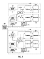
- FIG. 7 is a circuit diagram showing an apparatus for performing a handoff according to the fourth preferred embodiment of the present invention.
- Like elements are given like or corresponding reference numerals in the second, third and fourth preferred embodiments. Thus, dual explanations of the same elements are avoided.
- the weight addition operation according to the second preferred embodiment of the present invention is done after the multiplication operation using a data sequence to be sent and the pilot symbol.
- the multiplication operation according to the fourth preferred embodiment of the present invention is done by using the pilot symbol, after the weight addition operation using a data sequence to be sent.
- a second multiplexer 414 for transmitting path A is input with the multiplication result output by the weight adder 214 and the null symbol or the pilot symbols S 1 , S 2 .
- the multiplexer 414 multiplies the multiplication result by the pilot symbol S 1 , S 2 or the null symbol, and outputs a channel assumption value.
- a second multiplexer 415 for transmitting path B is input with the multiplication result output by the weight adder 215 and the null symbol or the reversed pilot symbols ⁇ S 1 , ⁇ S 2 .
- the multiplexer 415 multiplies the multiplication result by the reversed pilot symbol ⁇ S 1 , ⁇ S 2 or the null symbol, and outputs a channel assumption value.
Abstract
Description
Claims (16)
Applications Claiming Priority (2)
| Application Number | Priority Date | Filing Date | Title |
|---|---|---|---|
| JP313591/2001 | 2001-10-11 | ||
| JP2001313591A JP3923770B2 (en) | 2001-10-11 | 2001-10-11 | Handoff control method and handoff control circuit |
Publications (2)
| Publication Number | Publication Date |
|---|---|
| US20030081570A1 US20030081570A1 (en) | 2003-05-01 |
| US7289470B2 true US7289470B2 (en) | 2007-10-30 |
Family
ID=19132038
Family Applications (1)
| Application Number | Title | Priority Date | Filing Date |
|---|---|---|---|
| US10/268,101 Expired - Fee Related US7289470B2 (en) | 2001-10-11 | 2002-10-10 | Method and apparatus of performing handoff |
Country Status (2)
| Country | Link |
|---|---|
| US (1) | US7289470B2 (en) |
| JP (1) | JP3923770B2 (en) |
Cited By (1)
| Publication number | Priority date | Publication date | Assignee | Title |
|---|---|---|---|---|
| US20070147370A1 (en) * | 2005-12-26 | 2007-06-28 | Fujitsu Limited | Apparatus and method for resetting physical channel |
Families Citing this family (1)
| Publication number | Priority date | Publication date | Assignee | Title |
|---|---|---|---|---|
| JP4785377B2 (en) * | 2004-12-14 | 2011-10-05 | 株式会社エヌ・ティ・ティ・ドコモ | Radio channel control station, mobile communication system, and mobile communication method |
Citations (9)
| Publication number | Priority date | Publication date | Assignee | Title |
|---|---|---|---|---|
| US5101501A (en) * | 1989-11-07 | 1992-03-31 | Qualcomm Incorporated | Method and system for providing a soft handoff in communications in a cdma cellular telephone system |
| US5483668A (en) * | 1992-06-24 | 1996-01-09 | Nokia Mobile Phones Ltd. | Method and apparatus providing handoff of a mobile station between base stations using parallel communication links established with different time slots |
| US5507035A (en) * | 1993-04-30 | 1996-04-09 | International Business Machines Corporation | Diversity transmission strategy in mobile/indoor cellula radio communications |
| WO2000051265A1 (en) | 1999-02-22 | 2000-08-31 | Motorola Inc. | Method and system using transmit diversity techniques |
| US20010001762A1 (en) * | 1997-08-15 | 2001-05-24 | Telefonaktiebolaget L M Ericsson | Method and system in a mobile radio system |
| US6611675B1 (en) * | 2000-09-26 | 2003-08-26 | Nokia Mobile Phone Ltd. | Antenna verification method for advanced closed loop mode-one transmitter antenna diversity |
| US6678249B2 (en) * | 2002-02-14 | 2004-01-13 | Nokia Corporation | Physical layer packet retransmission handling WCDMA in soft handover |
| US6708030B1 (en) * | 1998-08-14 | 2004-03-16 | Nec Corporation | Selection method of a handoff system in a CDMA mobile communication system |
| US20040162021A1 (en) * | 2001-05-02 | 2004-08-19 | Hiroyuki Seki | Transmitting deversity system |
-
2001
- 2001-10-11 JP JP2001313591A patent/JP3923770B2/en not_active Expired - Fee Related
-
2002
- 2002-10-10 US US10/268,101 patent/US7289470B2/en not_active Expired - Fee Related
Patent Citations (9)
| Publication number | Priority date | Publication date | Assignee | Title |
|---|---|---|---|---|
| US5101501A (en) * | 1989-11-07 | 1992-03-31 | Qualcomm Incorporated | Method and system for providing a soft handoff in communications in a cdma cellular telephone system |
| US5483668A (en) * | 1992-06-24 | 1996-01-09 | Nokia Mobile Phones Ltd. | Method and apparatus providing handoff of a mobile station between base stations using parallel communication links established with different time slots |
| US5507035A (en) * | 1993-04-30 | 1996-04-09 | International Business Machines Corporation | Diversity transmission strategy in mobile/indoor cellula radio communications |
| US20010001762A1 (en) * | 1997-08-15 | 2001-05-24 | Telefonaktiebolaget L M Ericsson | Method and system in a mobile radio system |
| US6708030B1 (en) * | 1998-08-14 | 2004-03-16 | Nec Corporation | Selection method of a handoff system in a CDMA mobile communication system |
| WO2000051265A1 (en) | 1999-02-22 | 2000-08-31 | Motorola Inc. | Method and system using transmit diversity techniques |
| US6611675B1 (en) * | 2000-09-26 | 2003-08-26 | Nokia Mobile Phone Ltd. | Antenna verification method for advanced closed loop mode-one transmitter antenna diversity |
| US20040162021A1 (en) * | 2001-05-02 | 2004-08-19 | Hiroyuki Seki | Transmitting deversity system |
| US6678249B2 (en) * | 2002-02-14 | 2004-01-13 | Nokia Corporation | Physical layer packet retransmission handling WCDMA in soft handover |
Non-Patent Citations (1)
| Title |
|---|
| "3rd Generation Partnership Project: Technical Specification Group Radio Access Network; Physical layer procedures (FDD) (Release 1999)", 3GGP TS 25.214 v3.8.0, (Sep. 2001). |
Cited By (2)
| Publication number | Priority date | Publication date | Assignee | Title |
|---|---|---|---|---|
| US20070147370A1 (en) * | 2005-12-26 | 2007-06-28 | Fujitsu Limited | Apparatus and method for resetting physical channel |
| US7558581B2 (en) * | 2005-12-26 | 2009-07-07 | Fujitsu Limited | Apparatus and method for resetting physical channel |
Also Published As
| Publication number | Publication date |
|---|---|
| JP2003125432A (en) | 2003-04-25 |
| US20030081570A1 (en) | 2003-05-01 |
| JP3923770B2 (en) | 2007-06-06 |
Similar Documents
| Publication | Publication Date | Title |
|---|---|---|
| JP2876517B2 (en) | CDMA / TDD base station apparatus, CDMA / TDD mobile station apparatus, CDMA / TDD wireless communication system, and CDMA / TDD wireless communication method | |
| KR100353641B1 (en) | Base station transmit antenna diversity apparatus and method in cdma communication system | |
| US9219522B2 (en) | Code division multiple access transmission antenna weighting | |
| US7356313B2 (en) | Method to enable open loop antenna transmit diversity on channels having dedicated pilots | |
| KR100575930B1 (en) | Method and apparatus for mode transition of transmit diversity in mobile communication system using transmit diversity | |
| JP2001069050A (en) | Communication terminal and channel estimate method | |
| JP2001512921A (en) | Method and apparatus for transmitting a signal in a communication system | |
| KR19980086626A (en) | Code Division Multiple Access Communication Device and Method | |
| EP1401120B1 (en) | Base station for mobile communication system | |
| JP2001111464A (en) | Base station device and method for radio transmission | |
| JP3397237B2 (en) | CDMA communication system, mobile station, and transmission power control method therefor | |
| JP4625017B2 (en) | Base station, radio network controller, and radio communication method | |
| JPWO2002058265A1 (en) | Path search method, path search device, and mobile terminal device | |
| KR100532311B1 (en) | Apparatus for transmit diversity demodulation in mobile communication system and method thereof | |
| US7289470B2 (en) | Method and apparatus of performing handoff | |
| JP4035381B2 (en) | A data reproducing apparatus for reproducing data from signals transmitted through a plurality of antennas. | |
| KR100275476B1 (en) | Wireless tranceiver for transmission diversity using maximum likelihood ratio combinning | |
| JP2004072660A (en) | Communication method and communication system | |
| EP2278729A1 (en) | Method for diversity transmission, transmitter, and receiver thereof | |
| JP2005117498A (en) | Device and method for data transmission | |
| JP2003018092A (en) | Communication terminal and radio communication method | |
| KR20060014877A (en) | Method and apparatus for beamforming using forward auxiliary pilot channel in mobile telecommunication systems |
Legal Events
| Date | Code | Title | Description |
|---|---|---|---|
| AS | Assignment |
Owner name: OKI ELECTRIC INDUSTRY CO., LTD., JAPAN Free format text: ASSIGNMENT OF ASSIGNORS INTEREST;ASSIGNOR:SHIMAZAKI, YOSHIHITO;REEL/FRAME:013635/0592 Effective date: 20021220 |
|
| FEPP | Fee payment procedure |
Free format text: PAYOR NUMBER ASSIGNED (ORIGINAL EVENT CODE: ASPN); ENTITY STATUS OF PATENT OWNER: LARGE ENTITY |
|
| AS | Assignment |
Owner name: OKI SEMICONDUCTOR CO., LTD., JAPAN Free format text: CHANGE OF NAME;ASSIGNOR:OKI ELECTRIC INDUSTRY CO., LTD.;REEL/FRAME:022408/0397 Effective date: 20081001 Owner name: OKI SEMICONDUCTOR CO., LTD.,JAPAN Free format text: CHANGE OF NAME;ASSIGNOR:OKI ELECTRIC INDUSTRY CO., LTD.;REEL/FRAME:022408/0397 Effective date: 20081001 |
|
| FPAY | Fee payment |
Year of fee payment: 4 |
|
| AS | Assignment |
Owner name: LAPIS SEMICONDUCTOR CO., LTD., JAPAN Free format text: CHANGE OF NAME;ASSIGNOR:OKI SEMICONDUCTOR CO., LTD;REEL/FRAME:032495/0483 Effective date: 20111003 |
|
| REMI | Maintenance fee reminder mailed | ||
| LAPS | Lapse for failure to pay maintenance fees | ||
| STCH | Information on status: patent discontinuation |
Free format text: PATENT EXPIRED DUE TO NONPAYMENT OF MAINTENANCE FEES UNDER 37 CFR 1.362 |
|
| FP | Lapsed due to failure to pay maintenance fee |
Effective date: 20151030 |