US7284904B2 - Electronic clinical thermometer - Google Patents
Electronic clinical thermometer Download PDFInfo
- Publication number
- US7284904B2 US7284904B2 US11/084,225 US8422505A US7284904B2 US 7284904 B2 US7284904 B2 US 7284904B2 US 8422505 A US8422505 A US 8422505A US 7284904 B2 US7284904 B2 US 7284904B2
- Authority
- US
- United States
- Prior art keywords
- temperature
- thermometer
- temperature sensor
- measured
- heater
- Prior art date
- Legal status (The legal status is an assumption and is not a legal conclusion. Google has not performed a legal analysis and makes no representation as to the accuracy of the status listed.)
- Expired - Lifetime
Links
Images


Classifications
-
- G—PHYSICS
- G01—MEASURING; TESTING
- G01K—MEASURING TEMPERATURE; MEASURING QUANTITY OF HEAT; THERMALLY-SENSITIVE ELEMENTS NOT OTHERWISE PROVIDED FOR
- G01K1/00—Details of thermometers not specially adapted for particular types of thermometer
- G01K1/16—Special arrangements for conducting heat from the object to the sensitive element
-
- G—PHYSICS
- G01—MEASURING; TESTING
- G01K—MEASURING TEMPERATURE; MEASURING QUANTITY OF HEAT; THERMALLY-SENSITIVE ELEMENTS NOT OTHERWISE PROVIDED FOR
- G01K7/00—Measuring temperature based on the use of electric or magnetic elements directly sensitive to heat ; Power supply therefor, e.g. using thermoelectric elements
- G01K7/42—Circuits effecting compensation of thermal inertia; Circuits for predicting the stationary value of a temperature
Definitions
- This invention relates to an electronic thermometer for estimating the temperature at an inner position of a live body based on temperature data taken on the body surface. More particularly, the invention relates to such an electronic thermometer using an equation of thermal conduction for making such an estimate.
- thermometer When a conventional clinical thermometer such as a mercury thermometer is used to measure the temperature of a body by having it held under an arm or the tongue, the thermometer must be kept in that position until a thermal equilibrium is reached between the internal body position of interest and the surface temperature.
- a conventional clinical thermometer such as a mercury thermometer
- Japanese Patent Publication Tokko Hei 7-119656 B2 disclosed a method of using an equation for estimating the change in temperature while reaching an equilibrium and regarding such an equilibrium temperature as the body temperature.
- the measurement cannot be taken until a thermal equilibrium is reached between the surface and inner temperatures, it takes as long as 10 minutes until the measurement can be taken.
- This wait time can be reduced by a method of estimating the inner temperature from the manner in which temperature changes to reach the equilibrium, but it still takes about 90 seconds. This method cannot fully take into account individual variations among patients or environmental changes.
- the temperature on an external surface of a live body is measured directly on real time according to this invention and the body temperature at a normally inaccessible internal position of the body is estimated on the basis of values thus obtained.
- an equation of thermal conduction is used in reverse, Such an equation is solved as a lower-order equation such as a first-order differential equation including measurable physical quantities such as the body surface temperature and the thermal flux as variables.
- the desired internal temperature is then estimated by directly measuring these physical quantities. If as many different measured quantities are obtained as there are variables, the internal temperature can be obtained accurately and quickly by solving simultaneous first-order equations.
- An electronic clinical thermometer embodying this invention may be characterized as comprising a temperature sensor for measuring temperature, a heat flux sensor disposed proximally to the temperature sensor for measuring heat flux at nearly the same position (so as to be substantially under the same thermal condition) where the temperature sensor measures temperature, a controller for controlling the temperature sensor and the heat flux sensor to make measurements with them at a specified time interval, a memory for storing values measured by the temperature sensor and the heat flux sensor, and a calculator for calculating estimated temperature at a specified internal body position from the measured values of temperature and heat flux.
- the heat flux sensor is a device for measuring the quantity of heat which flows through a unit area per unit time and includes devices that calculate the heat flux from other physical quantities.
- thermometer it is advantageous to place the temperature and heat flux sensors proximally to each other such that the thermometer can be made compact. If the sensor part including these sensors can be made compact, its heat capacity is reduced, and since quicker changes in temperature can be generated, the time required for the measurement can be reduced.
- thermoly insulating member it is also preferable to dispose the temperature and heat flux sensors on a thermally insulating member because the effects of heat movement not from the body being measured can thus be eliminated or at least reduced such that the signal-to-noise ratio can be improved.
- a heater is provided in the thermometer. If the temperature difference is great between the target body for measurement and the environmental temperature, for example, the temperature of the part of the body through which heat travels from the internal target position to the sensors may be heated by the heater such that measurements can be taken with the temperature differences inside the body reduced. In this manner, the temperature changes inside the body become stabilized and more accurate measurements become possible. The time required for the measurement can also be reduced. If a thermally insulating member is introduced between the heater and the sensors, a stable heat gradient can be formed between the heater and the sensors such that the temperature and heat flux sensors are placed in a more suitable temperature condition for the measurement and hence that more accurate measurements are possible.
- thermometer embodying this invention may be characterized as having two (first and second) temperature sensors each for measuring temperature, a first thermally insulating member disposed between the first temperature sensor and a target body to be measured, a second thermally insulating member having a different thermal conductivity and being disposed between the second temperature sensor and the target body, a controller for controlling these temperature sensors to make measurements at specified time intervals, a memory for storing first measured values obtained by the first temperature sensor and second measured values obtained by the second temperature sensor, and a calculator for calculating estimated temperature at a specified internal body position from the first and second measured values.
- the physical quantities to be measured are temperatures at two different points contacting thermally insulating members having different thermal conductivity values.
- thermometer it may be advantageous to include a heater for reasons described above.
- Still another electronic clinical thermometer embodying this invention may be characterized as comprising a constant-temperature heater to be kept at a specified temperature, a temperature sensor for measuring temperature, a controller for controlling the temperature sensor and the constant-temperature heater to make measurements at specified time intervals, a memory for storing the specified temperature and measured values obtained by the temperature sensor, and a calculator for calculating estimated temperature at a specified internal body position from the specified temperature and the measured values.
- the constant-temperature heater in this case is used to prepare a body part which is heated thereby and stays at this specified temperature. It is possible to thus solve the equation of heat conduction by measuring the temperature at another body position.
- a probe may be formed for making contact to a body part in a planar shape or in an elongated shape of a bar such that even an infant can easily keep it in position in a stable manner.
- FIG. 1 is a sectional view of a portion of a patient's body for explaining the principle of heat conduction.
- FIG. 2 is an external plan view of an electronic thermometer embodying the invention.
- FIG. 3 is a sectional view of the thermometer of FIG. 2 taken along line 3 - 3 .
- FIG. 4 is a block diagram for showing the circuit structure of the thermometer of FIG. 2 .
- FIG. 5 is a flowchart of the process of taking a measurement by a thermometer according to a first embodiment of this invention.
- FIGS. 6A , 6 B and 6 C are examples of displays on the display device.
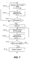
- FIG. 7 is a portion of the flowchart of FIG. 5 shown more in detail.
- FIG. 8A is a side view and FIG. 8B is a bottom view of another electronic thermometer embodying this invention.
- FIG. 9A is a sectional view of the probe taken along line 9 A- 9 A of FIG. 8B and FIG. 9B is a plan view of the insulating member in the probe shown in FIG. 8A .
- FIG. 10 is a flowchart of the process of taking a measurement by a thermometer according to a second embodiment of this invention.
- FIG. 11 is a sectional view of a portion of a patient's body for explaining the principle of body temperature measurement by a thermometer according to a third embodiment of this invention.
- FIG. 12 is an external plan view of an electronic thermometer according to a third embodiment of the invention.
- FIG. 13 is a sectional view of the thermometer of FIG. 12 taken along line 13 - 13 .
- FIG. 14 is a block diagram for showing the circuit structure of the thermometer of FIG. 12 .
- FIG. 15 is a flowchart of the process of taking a measurement by a thermometer according to a third embodiment of this invention.
- FIG. 16 is a portion of the flowchart of FIG. 15 shown more in detail.
- FIG. 17A is a side view and FIG. 17B is a bottom view of another thermometer according to the third embodiment of the invention.
- FIG. 18A is a sectional view taken along line 18 A- 18 A of FIG. 17B
- FIG. 18B is a bottom view of the insulating layers of the thermometer of FIG. 18A .
- FIG. 19 is a flowchart of the process of taking a measurement by a thermometer according to a fourth embodiment of this invention.
- FIG. 20 is a sectional view of a portion of a patient's body for explaining the principle of body temperature measurement by a thermometer according to a fifth embodiment of this invention.
- FIG. 21 is an external plan view of an electronic thermometer according to the fifth embodiment of the invention.
- FIG. 22 is a sectional view of the thermometer of FIG. 21 taken along line 22 - 22 of FIG. 21 .
- FIG. 23 is a block diagram for showing the circuit structure of the thermometer of FIG. 22 .
- FIG. 24 is a flowchart of the process of taking a measurement by a thermometer according to the fifth embodiment of this invention.
- FIG. 25 is a portion of the flowchart of FIG. 24 shown more in detail.
- FIG. 26A is a side view and FIG. 26B is a bottom view of a thermometer according to the fifth embodiment of the invention.
- FIG. 27A is a sectional view taken along line 27 A- 27 A of FIG. 26B
- FIG. 27B is a bottom view of the insulating layers of the thermometer of FIG. 27A .
- FIG. 1 shows T b as the temperature at an internal position of a patient to be estimated and T 1 as the temperature at an externally exposed body surface position, separated from the target position by a distance of h.
- T b T 1 +( h / ⁇ ) q 1 (1) and this means that if two or more sets of values for T 1 and q 1 are measured, the value of T b can be estimated
- the temperature at an internal body position can be estimated by a minimum of one measurement because there is no need to take in account any change with time. By making measurement for a plurality of times, accurate results can be obtained even by using a zeroth-order equation. If a higher-order equation is used, even more accurate estimates become possible.
- the surface temperature T 1 on the patient's body can be measured by means of a temperature sensor, and the heat flux can be measured by means of a heat flux sensor.
- a practically usable temperature sensor include IC temperature sensors using temperature characteristics such as platinum resistors, thermistors, thermo-couples and transistors.
- Examples of a heat flux sensor include layered structures and thermopiles.
- FIG. 2 shows an electronic thermometer 1 according to a first embodiment of the invention comprising a main body 2 which is approximately in the shape of a rectangular parallelopiped and a probe 3 which protrudes longitudinally in the shape of a bar from the main body 2 such that the user may hold the main body 2 to insert the probe under an arm or under the tongue.
- the main body 2 contains a display device 4 such as an LCD for displaying data such as a measured value and a power switch 5 .
- the probe 3 is approximately circular in cross-section, as shown in FIG. 3 , and its outer surface is covered with a thin material 6 such as SUS having a high thermal conductivity. On the inner surface of this cover material 6 , a temperature sensor 7 and a heat flux sensor 8 are disposed proximally to each other.
- this cover material 6 is covered with a layer of a thermally insulating member 9 .
- a heater 10 is disposed on the inner surface of this insulating layer 9 according to a second embodiment of the invention.
- the aforementioned first embodiment of the invention assumes the absence of this heater 10 .
- the temperature sensor 7 and the heat flux sensor 8 are preferably disposed as closely as possible to each other so as to be at the same temperature. If they are insulated from each other, they may be disposed in contact with each other.
- the insulating layer 9 is hollow, surrounding an empty space 90 inside. Lead lines (now shown) from the temperature sensor 7 and the heat flux sensor 8 may be passed therethrough to the main body 2 .
- the insulating layer 9 may be provided in the form of a film such that lead lines can be extended to the main body 2 along the baseboard for the film.
- a thin membrane of a resin material such as acryl, nylon, polyimides, polyesters and polyethylene may be used as the insulating member 9 .
- the probe 3 can be made compact if the temperature sensor 7 and the heat flux sensor 8 can be disposed close to each other. If the temperature sensor 7 and the heat flux sensor 8 are disposed close to each other, furthermore, the overall volume of the probe 3 and its thermal capacity can be reduced such that this has the favorable effect of speeding up the response to a temperature change and hence of reducing the time required to complete the measurement. Moreover, the freedom of design choice is also improved. Since the temperature sensor 7 and the heat flux sensor 8 are disposed on an insulating layer 9 , effects on temperature and heat flux due to heat from the target body can be reduced or eliminated, and the signal-to-noise ratio of the sensor can be improved for higher precision measurements.
- the electronic thermometer 1 comprises a controller 12 , a driver 13 , an A/D converter 14 , a calculator 15 , a memory 16 , a power source 17 and a buzzer 18 , in addition to the aforementioned temperature sensor 7 , heat flux sensor 8 , the power source 5 and the display device 4 .
- the controller 12 comprises a CPU and serves to control the thermometer as a whole.
- the driver 13 is for driving the temperature sensor 7 and the heat flux sensor 8 on the basis of signals received from the controller 12 . Signals outputted from the driver 13 are converted into digital signals by the A/D converter 14 and inputted to the calculator 15 .
- the calculator 15 performs various calculations such as for estimating the temperature of an internal target body position on the basis of the digital signals received from the A/D converter 14 and/or measured temperature and heat flux values stored in the memory 16 , and outputs the results of its calculations to the controller 12 .
- the calculator 15 serves to store specified data in the memory 16 and to retrieve data from the memory 16 to carry out specified calculations.
- the power source 17 may comprise a battery and serves to supply electric power to the controller 12 and the driver 13 .
- the power switch 5 is for switching on and off the supply of power from the power source 17 .
- the buzzer 18 is for generating a specified sound in response to a command from the controller 12 to alert the user of a certain situation. According to an embodiment where the heater 10 is provided, it is operated through the driver 13 .
- FIG. 5 is referenced next to explain the process for measuring an internal body temperature.
- Step S 101 a preliminary temperature measurement is taken by means of the temperature sensor 7 (Step S 102 ) to determine whether or not this preliminarily obtained temperature is within a specified range (Step S 103 ). If the measured temperature is not within the specified range (NO in Step S 103 ), a display is made to this effect on the display device 4 (Step S 104 ) and the power is switched off (Step S 105 ).
- Step S 106 a display is made to this effect on the display device 4 such as shown in FIG. 6A and the buzzer 18 may also be beeped to inform that the thermometer is ready to be used.
- the temperature sensor 7 and the heat flux sensor 8 are operated through the driver 13 and values of T 1 , q 1 and dT 1 /dt are collected (Step S 107 ). These data are now used by the calculator 15 to estimate the temperature at an internal target position (Step S 108 ).
- Step S 109 the program checks to determine whether or not a start flag (to be explained below) is “1” or not (Step S 109 ). If the start flag is “0” (NO in Step S 109 ), it is checked whether or not a specified condition (to be explained below) for starting the temperature measurement is satisfied (Step S 110 ). If this condition is found to be satisfied (YES in Step S 110 ), it is displayed on the display device 4 that a measurement is now being taken (Step S 111 ). FIG. 6B shows an example of such a display, causing the symbol “° C.” to blink. The start flag is then set to “1” (Step S 112 ) and the program returns to Step S 107 .
- a start flag to be explained below
- Step S 113 If the start flag is “1” in Step S 109 , it is checked (as will be explained in detail below) whether or not data that are sufficient for a measurement have been collected (Step S 113 ). If sufficient data have not been collected (NO in Step S 113 ), the program returns to Step S 107 to repeat the collection of data. If sufficient data have been collected (YES in Step S 113 ), the result of measurement is displayed on the display device 4 , say, as shown in FIG. 6C and the buzzer 18 may be caused to beep twice to indicate that the result of measurement has been displayed (Step S 114 ). Thereafter, power is automatically shut off (Step S 115 ) after a wait period of a specified length of time (Step S 115 ).
- Step S 107 The portion of the program explained above from Step S 107 to Step S 113 is shown more in detail in FIG. 7 .
- the condition may be, for example, that the calculated temperature be within the range of 35-42° C. but this is not intended to limit the scope of the invention.
- Step S 111 the start flag is set to “1” (Step S 112 ) as explained with reference to FIG. 5 and T 1 , q 1 and dT 1 /dt are measured (Step S 107 - 2 ) to calculate the temperature for the second time (Step S 108 - 2 ). Since the start flag is set to “1”, the program proceeds to Step S 113 to check whether sufficient data have been collected. If not, the program returns to Step S 107 . If sufficient data have been collected, the result of the measurement is displayed (Step S 114 ).
- the determination whether data sufficient for measurement have been collected may be made by examining whether or not a plurality of consecutively calculated temperature values are, say, within 0.01° C. of one another.
- FIGS. 8A and 8B show another electronic thermometer 11 which may be considered a variation of the first embodiment of the invention, structured in the shape of a flat rectangular parallelopiped with one end in a semi-circular form from which a probe 20 in the form of a circular column protrudes.
- a display device 4 comprising an LCD and a power switch 5 are disposed on the opposite surface.
- the probe 20 has its upper and side surfaces covered with a thin cover layer 26 , say, of SUS.
- a temperature sensor 7 and a heat flux sensor 8 are disposed on the lower surface of the top part 26 a of the cover layer 26 .
- a circular disk-shaped insulating member 9 is disposed below the top part 26 a of the cover layer 26 , sandwiching the temperature sensor 7 and the heat flux sensor 8 with the top part 26 a of the cover layer 26 .
- a heater 10 may be disposed (according to the second embodiment of the invention) on the lower surface of the insulating member 9 .
- the temperature sensor 7 and the heat flux sensor 8 are positioned on the top part 26 a of the cover layer 26 proximally to each other.
- thermometer 11 thus structured is particularly advantageous for use by an infant who may find it difficult to hold the probe steadily under an arm or under the tongue.
- FIG. 4 also shows a thermometer 21 according to the second embodiment of the invention which is different from the thermometer 1 according to the first embodiment of the invention in that there is a heater 10 which is activated by a signal from the controller 12 .
- the purpose of the heater 10 in the thermometer 21 is to preheat the temperature sensor 7 and the heat flux sensor 8 so as to preliminarily reduce the initial difference between the temperature to be estimated at an internal target body position and those of the temperature sensor 7 and the heat flux sensor 8 such that the time required for the measurement can be reduced.
- the insulator layer 9 separating the heater 10 from the temperature sensor 7 and the heat flux sensor 8 allows them to be placed close together such that the probe 3 can be made compact and the temperature change can be stabilized for more accurate measurement.
- Steps S 201 -S 205 are the same respectively as Steps S 101 -S 105 of FIG. 5 and hence will not be repetitiously explained.
- Step S 206 it is determined in Step S 206 whether or not a preheating is required on the basis of the temperature measured preliminarily in Step 202 . Such preheating may be deemed necessary if the measured temperature is below a specified level such as 30° C.
- Step S 206 If it is decided that a preheating is necessary (YES in Step S 206 ), the heater 10 is activated (Step S 207 ) until the measured temperature indicates that the preheating is no longer necessary (NO in Step S 206 ), and then a “ready” display is made on the display device (Step S 208 ).
- the processes from the end of Step S 208 to Step S 217 are the same as those from Step S 106 to Step S 115 shown in FIG. 5 and hence will not be repetitiously explained. It is to be noted that the heating by the heater 10 is finished before the measurement is taken and the heater 10 is not active during the measurement.
- FIG. 11 is referenced next to explain the principle of temperature measurement by a thermometer 31 according to a third embodiment of the invention shown in FIGS. 12 and 13 .
- the third embodiment is characterized as using two insulating members with different thermal conductivity values, or to estimate the temperature T b at an internal target body position by measuring temperatures T 1 and T 2 at different surface positions at a distance h from the target position respectively through an insulating layer with thermal conductivity ⁇ 1 and ⁇ 2 .
- T b T s1 +( h/ ⁇ b ) q 1 +( h 2 /2 ⁇ 1 )( dT 1 /dt )
- T b T s2 +( h/ ⁇ b ) q 2 +( h 2 /2 ⁇ 2 )( dT 2 /dt )
- ⁇ b is the thermal conductivity of the body
- T s1 and T s2 are respectively the temperature at the contact surface between the body and the first and second insulating member
- q 1 and q 2 are respectively the heat flux through the first and second insulating member
- ⁇ 1 and ⁇ 2 are respectively the thermal diffusivity of the first and second insulating member.
- T s1 T s2 .
- FIG. 12 shows an external view of a thermometer 31 according to the third embodiment of the invention. Since its external appearance is the same as that of the thermometer according to the first embodiment, the same symbols used in FIG. 2 are used for corresponding components and they are not repetitiously explained with reference to FIG. 12 .
- FIG. 13 shows its internal structure. Its probe 33 is identical to the probe 3 shown in FIG. 3 except for the structure of the insulating member, having a first insulating layer 39 a and a second insulating layer 39 b with different thermal conductivity values disposed on the inner surface of the cover 6 .
- a first temperature sensor 37 a is on the inner surface of the first insulating layer 39 a and a second temperature sensor 37 b is on the inner surface of the second insulating layer 39 b .
- a heater 10 may be disposed (according to a fourth embodiment of the invention) on the inner surface of either of the insulating layers 39 a and 39 b opposite the first and second temperature sensors 37 a and 37 b , separated therefrom across the hollow interior 90 of the insulating layers 39 a and 39 b .
- Lead lines (not shown) connected to the temperature sensors 37 a and 37 b may be extended through this hollow interior 90 .
- Thermometers according to the third embodiment is advantageous in that they are less costly than the embodiments requiring the use of a heat flux sensor.
- FIG. 14 shows the internal circuit structure of the thermometer 31 , which is similar to that shown by the block diagram of FIG. 4 except that the first and second temperature sensors 37 a and 37 b take the places of the temperature sensor 7 and the heat flux sensor 8 of FIG. 4 .
- FIG. 15 is referenced next to explain the process for measuring an internal body temperature.
- Steps S 301 -S 305 and the step of shutting off the power are the same respectively as Steps S 101 -S 105 and Step S 115 of FIG. 5 , and hence will not be repetitiously explained.
- the first or second temperature sensor 37 a or 37 b is used in Step 302 for preliminarily measuring the temperature and four pieces of data T 1 , T 2 , dT 1 /dt and dT 2 /dt are collected in Step S 307 .
- FIG. 16 shows more in detail a portion of the flowchart of FIG. 15 from Step S 307 to Step S 313 .
- This is similar to the portion explained above with reference to FIG. 7 except that four kinds of data T 1 , T 2 , dT 1 /dt and dT 2 /dt are collected in Steps S 307 - 1 and S 307 - 2 and since these four variables are to be obtained, that the data must be collected four or more times.
- the determination in Step S 313 may be made by examining whether or not a plurality of consecutively calculated temperature values are, say, within 0.01° C. of one another.
- FIGS. 17A and 17B show another thermometer 301 which is a variation of the third embodiment, having a rectangular columnar probe 302 protruding at one end of one of its main surfaces and a display device 4 comprising an LCD and a power switch 5 disposed on the opposite surface.
- FIGS. 18A and 18B show the interior structure of the probe 302 , having its top and side surfaces covered with a thin material 326 comprising SUS. Thermally insulating members 39 a and 39 b having different conductivity values are disposed adjacent each other below the top part 326 a of the insulating member 326 . The side wall portions of the insulating member 326 are indicated as 326 b .
- the temperature sensors 37 a and 37 b are respectively disposed on the lower surface of the insulating members 39 a and 39 b .
- a heater (not shown) may also be disposed on the lower surface of either of the insulating members 39 a and 39 b (according to the fourth embodiment of the invention). This variation of the third embodiment is convenient for use by an infant who may find it difficult to hold the probe steadily under an arm or under the tongue.
- FIGS. 13 and 14 also show a thermometer 41 according to the fourth embodiment of the invention, which is different from the third embodiment in that a heater 10 is included, adapted to be driven by a signal transmitted from the driver 13 .
- the advantage of the fourth embodiment is that the heater 10 preheats the temperature sensors 37 a and 37 b and the insulating members 39 a and 39 b such that the time required for the temperature measurement can be reduced.
- FIG. 19 is referenced next to explain the process for measuring an internal body temperature by means of the thermometer 41 according to the fourth embodiment of the invention.
- Steps S 401 -S 405 and Steps S 408 -S 416 are the same respectively as Steps S 101 -S 105 and Steps 106 - 115 of FIG. 5 , hence will not be repetitiously explained.
- Step S 406 it is determined in Step S 406 whether or not a preheating is required on the basis of the temperature measured preliminarily in Step 402 . Such preheating may be deemed necessary if the measured temperature is below a specified level such as 30° C. If it is determined in Step S 406 that a preheating step is required, the heater 10 is activated for preheating (Step S 407 ) as done in Step S 207 with reference to FIG. 10 .
- FIG. 20 is referenced next to explain the principle of temperature measurement by a thermometer 51 according to a fifth embodiment of the invention shown in FIGS. 21 and 22 .
- the fifth embodiment is characterized as estimating the temperature T b at an internal target body position separated from a body surface by a distance of h by measuring the surface temperature T 3 detected by a temperature sensor in contact with the body surface and the specified temperature T 4 of a heater which contacts the body surface through a thermal insulator.
- ⁇ is the density of the insulator
- c is its specific heat
- X is its thickness
- ⁇ is its thermal conductivity
- ⁇ b is the thermal conductivity of the body
- q 3 is the heat flux through the insulator
- q b is the heat flux through the body
- ⁇ 2 ⁇ / ⁇ cX 2 .
- T b can be estimated by measuring two or more values of dT 3 /dt and T 3 .
- thermometer 51 As shown in FIG. 21 , the external view of the thermometer 51 is the same as that of the thermometer 1 according to the first embodiment shown in FIG. 2 .
- the internal structure of its probe 53 is also similar to that of the thermometer 1 shown in FIG. 3 except that a temperature sensor 7 is disposed on the inner surface of the cover 6 and also that a thermally insulating member 9 is disposed so as to sandwich the temperature sensor 7 with the cover 6 .
- the insulating member 9 is cylindrically formed with a hollow interior 90 .
- a constant-temperature heater 52 is disposed on the inner surface of the insulating member 9 at a position opposite to the temperature sensor 7 . Lead lines (not shown) connected to the temperature sensor 7 and the heater 52 are extended through this hollow interior 90 .
- thermometer 51 As shown in FIG. 23 , the interior circuit structure of the thermometer 51 is similar to that of the thermometer 1 shown in FIG. 4 except a constant-temperature heater 52 is provided to be driven by the driver 13 according to a signal outputted from the controller 12 .
- the medium through which heat flows from the internal target position in the body to the temperature sensor 7 is heated by the heater such that the temperature difference is reduced.
- the temperature change of the probe 53 inclusive of the temperature sensor 7 becomes stabilized.
- the probe 53 is of a simpler structure, including essentially only the temperature sensor 7 and the constant-temperature heater 52 such that freedom of choice in positioning the components is improved.
- the presence of the insulating member 9 between the temperature sensor 7 and the heater 52 serves to create a stable temperature gradient such that the temperature sensor can be placed under a suitable temperature condition for the measurement.
- FIG. 24 is referenced next to explain the process for measuring an internal body temperature by means of the thermometer 51 according to the fourth embodiment of the invention.
- Steps S 501 -S 505 and Steps S 510 -S 518 are the same respectively as Steps S 101 -S 105 and Steps 107 - 115 of FIG. 5 , hence will not be repetitiously explained.
- the heater 51 is switched on (Step S 506 ) and temperature is measured by the temperature sensor 7 (Step S 507 ) if the temperature measured in Step S 502 is within a specified range. If the temperature is not stable (NO in Step S 508 ), the program returns to Step S 506 .
- Step S 508 If the temperature is stable (YES in Step S 508 ), a display is made to the effect that it is ready to take a measurement (Step S 509 ).
- Step S 510 unlike in Step S 107 , two kinds of data T 1 and dT 1 /dt are collected, and the heater 52 is not necessarily switched off while the data are collected. Since the purpose of the heater 52 is to remain at a constant temperature level, it may be intermittently switched on and off.
- Step S 510 - 1 to Step S 517 The portion of the flowchart of FIG. 24 from Step S 510 to Step S 517 is shown in FIG. 25 more in detail.
- the processes from Step S 510 - 1 to Step S 517 are the same as explained above with reference to FIG. 7 except that two kinds of data T 1 and dT 1 /dt are collected in the present embodiment in Steps S 510 - 1 and S 510 - 2 and, since there are two variables T 1 and dT 1 /dt to be obtained, that data are collected at least twice.
- the determination in Step S 516 may be made by examining whether or not a plurality of consecutively calculated temperature values are, say, within 0.01° C. of one another.
- FIGS. 26A and 26B show another thermometer 501 which is a variation of the fifth embodiment, having a rectangular columnar probe 520 protruding at one end of one of its main surfaces and a display device 4 comprising an LCD and a power switch 5 disposed on the opposite surface.
- FIGS. 27A and 27B show the interior structure of the probe 520 having its top and side surfaces covered with a thin material 526 comprising SUS or the like.
- a temperature sensor 7 is disposed below the top portion 526 a of the cover 526 .
- the side wall portions of the insulating material 526 are indicated as 526 b .
- a thermally insulating member 59 is disposed below the top portion 526 a of the cover 526 so as to sandwich the temperature sensor 7 with the top portion 526 a of the cover 526 .
- a constant-temperature heater 52 is disposed in contact with the insulating member 59 .
- the temperature at an internal target body position is calculated by making measurements on real time on the external surface of the body and by using the equation of thermal conduction.
- the measurements can be made accurately and quickly.
Abstract
An electronic clinical thermometer has a probe including a temperature sensor and a heat flux sensor which are controlled to make measurements at specified time intervals. The measured values are used in solving the equation of heat conduction to estimate the temperature of an internal body position. A heater may be included to preheat a body part in order to reduce the time required for measurement. The probe may use two temperature sensors to measure temperatures at two body surface positions through insulating members which are different in thermal conductivity.
Description
This is a divisional of application Ser. No. 10/120,297 filed Apr. 9, 2002, now U.S. Pat. No. 6,890,096, which claims priority on Japanese patent application 2001-113224 filed Apr. 11, 2001.
This invention relates to an electronic thermometer for estimating the temperature at an inner position of a live body based on temperature data taken on the body surface. More particularly, the invention relates to such an electronic thermometer using an equation of thermal conduction for making such an estimate.
When a conventional clinical thermometer such as a mercury thermometer is used to measure the temperature of a body by having it held under an arm or the tongue, the thermometer must be kept in that position until a thermal equilibrium is reached between the internal body position of interest and the surface temperature.
Japanese Patent Publication Tokko Hei 7-119656 B2 disclosed a method of using an equation for estimating the change in temperature while reaching an equilibrium and regarding such an equilibrium temperature as the body temperature.
It is desirable, however, to measure the internal body temperature of a patient directly. International Patent Publication WO-9850766 disclosed an electronic thermometer based on the method published in “Engineering of Heat Conduction” (at page 90) by Masahiro Shoji (published by Tokyo University). According to this method, temperatures are measured at two different positions and the temperature at a third position outside the region of the two positions is estimated. What is desired, however, is an electronic thermometer for measuring not a surface temperature but an inner temperature.
If the measurement cannot be taken until a thermal equilibrium is reached between the surface and inner temperatures, it takes as long as 10 minutes until the measurement can be taken. This wait time can be reduced by a method of estimating the inner temperature from the manner in which temperature changes to reach the equilibrium, but it still takes about 90 seconds. This method cannot fully take into account individual variations among patients or environmental changes.
As for the method according to International Patent Publication WO-9850766, the solution is unstable because the equation to be solved is non-linear and an accurate solution cannot be obtained without the help of a high-power computer, and a long computer time will be wasted.
It is therefore an object of this invention to provide an electronic clinical thermometer capable of accurately and quickly estimate the internal body temperature of a live body by measuring real-time external temperature values directly and calculating the temperature at the desired internal body position by solving an equation of thermal conduction and using the results of such measurements.
In view of the above and other objects of this invention, the temperature on an external surface of a live body is measured directly on real time according to this invention and the body temperature at a normally inaccessible internal position of the body is estimated on the basis of values thus obtained. For this purpose, an equation of thermal conduction is used in reverse, Such an equation is solved as a lower-order equation such as a first-order differential equation including measurable physical quantities such as the body surface temperature and the thermal flux as variables. The desired internal temperature is then estimated by directly measuring these physical quantities. If as many different measured quantities are obtained as there are variables, the internal temperature can be obtained accurately and quickly by solving simultaneous first-order equations.
An electronic clinical thermometer embodying this invention may be characterized as comprising a temperature sensor for measuring temperature, a heat flux sensor disposed proximally to the temperature sensor for measuring heat flux at nearly the same position (so as to be substantially under the same thermal condition) where the temperature sensor measures temperature, a controller for controlling the temperature sensor and the heat flux sensor to make measurements with them at a specified time interval, a memory for storing values measured by the temperature sensor and the heat flux sensor, and a calculator for calculating estimated temperature at a specified internal body position from the measured values of temperature and heat flux.
In order to solve the equation of thermal conduction in reverse to estimate the temperature at a specified internal body position, various physical quantities may be selected for measurement. According to this invention, temperature and heat flux at approximate the same places are selected as the physical quantities for this purpose. By measuring these physical quantities for a plurality of times at a specified interval, or specified intervals, different sets of measured quantities can be obtained, and these obtained quantities can be used to solve the equation of thermal condition and estimate the target temperature at the specified internal position of a body. In the above, the heat flux sensor is a device for measuring the quantity of heat which flows through a unit area per unit time and includes devices that calculate the heat flux from other physical quantities.
It is advantageous to place the temperature and heat flux sensors proximally to each other such that the thermometer can be made compact. If the sensor part including these sensors can be made compact, its heat capacity is reduced, and since quicker changes in temperature can be generated, the time required for the measurement can be reduced.
It is also preferable to dispose the temperature and heat flux sensors on a thermally insulating member because the effects of heat movement not from the body being measured can thus be eliminated or at least reduced such that the signal-to-noise ratio can be improved.
In some embodiments of the invention, a heater is provided in the thermometer. If the temperature difference is great between the target body for measurement and the environmental temperature, for example, the temperature of the part of the body through which heat travels from the internal target position to the sensors may be heated by the heater such that measurements can be taken with the temperature differences inside the body reduced. In this manner, the temperature changes inside the body become stabilized and more accurate measurements become possible. The time required for the measurement can also be reduced. If a thermally insulating member is introduced between the heater and the sensors, a stable heat gradient can be formed between the heater and the sensors such that the temperature and heat flux sensors are placed in a more suitable temperature condition for the measurement and hence that more accurate measurements are possible.
Another thermometer embodying this invention may be characterized as having two (first and second) temperature sensors each for measuring temperature, a first thermally insulating member disposed between the first temperature sensor and a target body to be measured, a second thermally insulating member having a different thermal conductivity and being disposed between the second temperature sensor and the target body, a controller for controlling these temperature sensors to make measurements at specified time intervals, a memory for storing first measured values obtained by the first temperature sensor and second measured values obtained by the second temperature sensor, and a calculator for calculating estimated temperature at a specified internal body position from the first and second measured values. In this embodiment, the physical quantities to be measured are temperatures at two different points contacting thermally insulating members having different thermal conductivity values. If these physical quantities are measured at specified intervals and different sets of measured values are obtained, they can be used to solve the equations for thermal conduction and to calculate the temperature of an internal target position inside the body. Other physical quantities such as coefficient of thermal conduction and specific heat may be measured. Two insulating members with same conductivity may be used if, for example, they are different in thickness. In a thermometer according to this embodiment of the invention, too, it may be advantageous to include a heater for reasons described above.
Still another electronic clinical thermometer embodying this invention may be characterized as comprising a constant-temperature heater to be kept at a specified temperature, a temperature sensor for measuring temperature, a controller for controlling the temperature sensor and the constant-temperature heater to make measurements at specified time intervals, a memory for storing the specified temperature and measured values obtained by the temperature sensor, and a calculator for calculating estimated temperature at a specified internal body position from the specified temperature and the measured values. The constant-temperature heater in this case is used to prepare a body part which is heated thereby and stays at this specified temperature. It is possible to thus solve the equation of heat conduction by measuring the temperature at another body position.
In all these thermometers according to different embodiments of this invention, a probe may be formed for making contact to a body part in a planar shape or in an elongated shape of a bar such that even an infant can easily keep it in position in a stable manner.
Throughout herein some of like components are indicated by the same numerals although they may be components of different thermometers and may not be described repetitiously for the sake of simplicity of description.
The invention is described next by way of examples. FIG. 1 shows Tb as the temperature at an internal position of a patient to be estimated and T1 as the temperature at an externally exposed body surface position, separated from the target position by a distance of h. The heat conductivity of the body is expressed as λ. If the flux of heat flow at the surface position is q1, it may be expressed as follows:
q 1=−λ(dT 1 /dx)=−λ(T 1 −T b)/h
where x represents the direction of the line connecting the internal target body position and the surface position where the surface body temperature and the heat flux are measured. (InFIG. 1 , qb indicates the heat flux at the internal body position.) From the above, one obtains:
T b =T 1+(h/λ)q 1 (1)
and this means that if two or more sets of values for T1 and q1 are measured, the value of Tb can be estimated
q 1=−λ(dT 1 /dx)=−λ(T 1 −T b)/h
where x represents the direction of the line connecting the internal target body position and the surface position where the surface body temperature and the heat flux are measured. (In
T b =T 1+(h/λ)q 1 (1)
and this means that if two or more sets of values for T1 and q1 are measured, the value of Tb can be estimated
The basic differential equation for heat conduction (or the heat transfer equation) may be written as follows:
∂T 1 /∂t=α(∂2 T 1 /∂x 2)
where α is the thermal diffusivity. If the second-order term is included in its solution, this gives:
T b =T 1+(h/λ)q 1+(h 2/2α)(dT 1 /dt) (2)
since q1=−λ(dT1/dx). This means that if three or more sets of values for T1, q1 and dT1/dt are measured, the value of Tb can be estimated.
If the equation is of zeroth-order, the temperature at an internal body position can be estimated by a minimum of one measurement because there is no need to take in account any change with time. By making measurement for a plurality of times, accurate results can be obtained even by using a zeroth-order equation. If a higher-order equation is used, even more accurate estimates become possible.
In the above, the surface temperature T1 on the patient's body can be measured by means of a temperature sensor, and the heat flux can be measured by means of a heat flux sensor. Examples of a practically usable temperature sensor include IC temperature sensors using temperature characteristics such as platinum resistors, thermistors, thermo-couples and transistors. Examples of a heat flux sensor include layered structures and thermopiles.
The temperature sensor 7 and the heat flux sensor 8 are preferably disposed as closely as possible to each other so as to be at the same temperature. If they are insulated from each other, they may be disposed in contact with each other. The insulating layer 9 is hollow, surrounding an empty space 90 inside. Lead lines (now shown) from the temperature sensor 7 and the heat flux sensor 8 may be passed therethrough to the main body 2. The insulating layer 9 may be provided in the form of a film such that lead lines can be extended to the main body 2 along the baseboard for the film. A thin membrane of a resin material such as acryl, nylon, polyimides, polyesters and polyethylene may be used as the insulating member 9. The probe 3 can be made compact if the temperature sensor 7 and the heat flux sensor 8 can be disposed close to each other. If the temperature sensor 7 and the heat flux sensor 8 are disposed close to each other, furthermore, the overall volume of the probe 3 and its thermal capacity can be reduced such that this has the favorable effect of speeding up the response to a temperature change and hence of reducing the time required to complete the measurement. Moreover, the freedom of design choice is also improved. Since the temperature sensor 7 and the heat flux sensor 8 are disposed on an insulating layer 9, effects on temperature and heat flux due to heat from the target body can be reduced or eliminated, and the signal-to-noise ratio of the sensor can be improved for higher precision measurements.
As shown in FIG. 4 , the electronic thermometer 1 comprises a controller 12, a driver 13, an A/D converter 14, a calculator 15, a memory 16, a power source 17 and a buzzer 18, in addition to the aforementioned temperature sensor 7, heat flux sensor 8, the power source 5 and the display device 4. The controller 12 comprises a CPU and serves to control the thermometer as a whole. The driver 13 is for driving the temperature sensor 7 and the heat flux sensor 8 on the basis of signals received from the controller 12. Signals outputted from the driver 13 are converted into digital signals by the A/D converter 14 and inputted to the calculator 15. The calculator 15 performs various calculations such as for estimating the temperature of an internal target body position on the basis of the digital signals received from the A/D converter 14 and/or measured temperature and heat flux values stored in the memory 16, and outputs the results of its calculations to the controller 12. In short, the calculator 15 serves to store specified data in the memory 16 and to retrieve data from the memory 16 to carry out specified calculations. The power source 17 may comprise a battery and serves to supply electric power to the controller 12 and the driver 13. The power switch 5 is for switching on and off the supply of power from the power source 17. The buzzer 18 is for generating a specified sound in response to a command from the controller 12 to alert the user of a certain situation. According to an embodiment where the heater 10 is provided, it is operated through the driver 13.
If the preliminarily measured temperature is within the specified range (YES in Step S103), a display is made to this effect on the display device 4 (Step S106) such as shown in FIG. 6A and the buzzer 18 may also be beeped to inform that the thermometer is ready to be used. Next, the temperature sensor 7 and the heat flux sensor 8 are operated through the driver 13 and values of T1, q1 and dT1/dt are collected (Step S107). These data are now used by the calculator 15 to estimate the temperature at an internal target position (Step S108).
Next, the program checks to determine whether or not a start flag (to be explained below) is “1” or not (Step S109). If the start flag is “0” (NO in Step S109), it is checked whether or not a specified condition (to be explained below) for starting the temperature measurement is satisfied (Step S110). If this condition is found to be satisfied (YES in Step S110), it is displayed on the display device 4 that a measurement is now being taken (Step S111). FIG. 6B shows an example of such a display, causing the symbol “° C.” to blink. The start flag is then set to “1” (Step S112) and the program returns to Step S107.
If the start flag is “1” in Step S109, it is checked (as will be explained in detail below) whether or not data that are sufficient for a measurement have been collected (Step S113). If sufficient data have not been collected (NO in Step S113), the program returns to Step S107 to repeat the collection of data. If sufficient data have been collected (YES in Step S113), the result of measurement is displayed on the display device 4, say, as shown in FIG. 6C and the buzzer 18 may be caused to beep twice to indicate that the result of measurement has been displayed (Step S114). Thereafter, power is automatically shut off (Step S115) after a wait period of a specified length of time (Step S115).
The portion of the program explained above from Step S107 to Step S113 is shown more in detail in FIG. 7 . After the display device 4 is caused to display that it is ready to take measurements, the values of T1, q1 and dT1/dt are measured three times (Step S107-1) and the calculation of the temperature at the target position is carried out for the first time (n=1) (Step S108-1). Since the start flag is still reset (“0”) at this moment, the program proceeds to Step S110 and, as explained above, the measurement-starting condition is checked. The condition may be, for example, that the calculated temperature be within the range of 35-42° C. but this is not intended to limit the scope of the invention.
If the calculated temperature is not within such a specified range, or if the specified condition for starting measurement is not satisfied (NO in Step S110), the program proceeds to Step S113 (as shown in FIG. 5 ) and it is checked if data that are sufficient for a measurement have been collected. This judgment may be taken by examining whether or not a plurality of successively calculated temperature values are nearly the same (say, to the second positions below the decimal point). Since this is the first (n=1) calculation and there is no other result to compare to, it is concluded in Step S113 that sufficient data have not been collected and the program returns to Step 107 to repeat the collection of data. If the specified condition is satisfied in Step S110, the display as shown in FIG. 6B is made (Step S111) and the start flag is set to “1” (Step S112) as explained with reference to FIG. 5 and T1, q1 and dT1/dt are measured (Step S107-2) to calculate the temperature for the second time (Step S108-2). Since the start flag is set to “1”, the program proceeds to Step S113 to check whether sufficient data have been collected. If not, the program returns to Step S107. If sufficient data have been collected, the result of the measurement is displayed (Step S114).
The determination whether data sufficient for measurement have been collected may be made by examining whether or not a plurality of consecutively calculated temperature values are, say, within 0.01° C. of one another.
As shown in FIG. 9A , the probe 20 has its upper and side surfaces covered with a thin cover layer 26, say, of SUS. A temperature sensor 7 and a heat flux sensor 8 are disposed on the lower surface of the top part 26 a of the cover layer 26. A circular disk-shaped insulating member 9 is disposed below the top part 26 a of the cover layer 26, sandwiching the temperature sensor 7 and the heat flux sensor 8 with the top part 26 a of the cover layer 26. A heater 10 may be disposed (according to the second embodiment of the invention) on the lower surface of the insulating member 9. As shown in FIG. 9B , the temperature sensor 7 and the heat flux sensor 8 are positioned on the top part 26 a of the cover layer 26 proximally to each other.
The thermometer 11 thus structured is particularly advantageous for use by an infant who may find it difficult to hold the probe steadily under an arm or under the tongue.
Next, the process of taking temperature measurement according to the second embodiment of the invention will be described with reference to FIG. 10 . As briefly explained above, FIG. 4 also shows a thermometer 21 according to the second embodiment of the invention which is different from the thermometer 1 according to the first embodiment of the invention in that there is a heater 10 which is activated by a signal from the controller 12.
The purpose of the heater 10 in the thermometer 21 is to preheat the temperature sensor 7 and the heat flux sensor 8 so as to preliminarily reduce the initial difference between the temperature to be estimated at an internal target body position and those of the temperature sensor 7 and the heat flux sensor 8 such that the time required for the measurement can be reduced. The insulator layer 9 separating the heater 10 from the temperature sensor 7 and the heat flux sensor 8 allows them to be placed close together such that the probe 3 can be made compact and the temperature change can be stabilized for more accurate measurement.
In FIG. 10 , Steps S201-S205 are the same respectively as Steps S101-S105 of FIG. 5 and hence will not be repetitiously explained. With this thermometer 21, however, it is determined in Step S206 whether or not a preheating is required on the basis of the temperature measured preliminarily in Step 202. Such preheating may be deemed necessary if the measured temperature is below a specified level such as 30° C.
If it is decided that a preheating is necessary (YES in Step S206), the heater 10 is activated (Step S207) until the measured temperature indicates that the preheating is no longer necessary (NO in Step S206), and then a “ready” display is made on the display device (Step S208). The processes from the end of Step S208 to Step S217 are the same as those from Step S106 to Step S115 shown in FIG. 5 and hence will not be repetitiously explained. It is to be noted that the heating by the heater 10 is finished before the measurement is taken and the heater 10 is not active during the measurement.
The third embodiment is characterized as using two insulating members with different thermal conductivity values, or to estimate the temperature Tb at an internal target body position by measuring temperatures T1 and T2 at different surface positions at a distance h from the target position respectively through an insulating layer with thermal conductivity λ1 and λ2. Thus, by solving the differential equation of thermal conduction by keeping the second-order terms, as done above, we obtain:
T b =T s1+(h/λ b)q 1+(h 2/2α1)(dT 1 /dt)
T b =T s2+(h/λ b)q 2+(h 2/2α2)(dT 2 /dt)
where λb is the thermal conductivity of the body, Ts1 and Ts2 are respectively the temperature at the contact surface between the body and the first and second insulating member, q1 and q2 are respectively the heat flux through the first and second insulating member, and α1 and α2 are respectively the thermal diffusivity of the first and second insulating member. Since we also have:
q 1=−λ1(dT 1 /dx)=−λ1(T 1 −T s1)/X
q 2=−λ2(dT 2 /dx)=−λ2(T 2 −T s2)/X
where X is the thickness of the insulating members, as shown inFIG. 11 , we obtain simultaneous equations in the form of:
T b =T s1 +A(T s1 −T 1)+B(dT 1 /dt)
T b =T s2 +C(T s2 −T 2)+D(dT 1 /dt). (3)
If the two temperature sensors are disposed close to each other and both insulating members are in contact with the body surface, Ts1=Ts2. Thus, by measuring T1, T2, dT1/dt and dT2/dt, it is possible to estimate Tb. In summary, it is possible to estimate the temperature at an internal position of a live body by measuring the temperatures and the time rate of their changes at surface positions through insulating members having different thermal conductivity values.
T b =T s1+(h/λ b)q 1+(h 2/2α1)(dT 1 /dt)
T b =T s2+(h/λ b)q 2+(h 2/2α2)(dT 2 /dt)
where λb is the thermal conductivity of the body, Ts1 and Ts2 are respectively the temperature at the contact surface between the body and the first and second insulating member, q1 and q2 are respectively the heat flux through the first and second insulating member, and α1 and α2 are respectively the thermal diffusivity of the first and second insulating member. Since we also have:
q 1=−λ1(dT 1 /dx)=−λ1(T 1 −T s1)/X
q 2=−λ2(dT 2 /dx)=−λ2(T 2 −T s2)/X
where X is the thickness of the insulating members, as shown in
T b =T s1 +A(T s1 −T 1)+B(dT 1 /dt)
T b =T s2 +C(T s2 −T 2)+D(dT 1 /dt). (3)
If the two temperature sensors are disposed close to each other and both insulating members are in contact with the body surface, Ts1=Ts2. Thus, by measuring T1, T2, dT1/dt and dT2/dt, it is possible to estimate Tb. In summary, it is possible to estimate the temperature at an internal position of a live body by measuring the temperatures and the time rate of their changes at surface positions through insulating members having different thermal conductivity values.
Instead of using two different insulating members as explained above, use may be made of two insulating members which may have the same thermal conductivity but are different in thickness.
The fifth embodiment is characterized as estimating the temperature Tb at an internal target body position separated from a body surface by a distance of h by measuring the surface temperature T3 detected by a temperature sensor in contact with the body surface and the specified temperature T4 of a heater which contacts the body surface through a thermal insulator. If ρ is the density of the insulator, c is its specific heat, X is its thickness, λ is its thermal conductivity, λb is the thermal conductivity of the body, q3 is the heat flux through the insulator and qb is the heat flux through the body, one obtains from the conservation law:
ρcX(dT 3 /dt)=q b −q 3=−λb(dT 3 /dx)+λ(dT 4 /dx),
or
dT 3 /dt=ω 1(T b −T 3)−ω2(T 3 −T 4),
where
ρcX(dT 3 /dt)=q b −q 3=−λb(dT 3 /dx)+λ(dT 4 /dx),
or
dT 3 /dt=ω 1(T b −T 3)−ω2(T 3 −T 4),
where
ω1=λb/ρcXh, and
ω2=λ/ρcX2.
Thus, since T4 is a known temperature, Tb can be estimated by measuring two or more values of dT3/dt and T3.
As shown in FIG. 21 , the external view of the thermometer 51 is the same as that of the thermometer 1 according to the first embodiment shown in FIG. 2 . The internal structure of its probe 53 is also similar to that of the thermometer 1 shown in FIG. 3 except that a temperature sensor 7 is disposed on the inner surface of the cover 6 and also that a thermally insulating member 9 is disposed so as to sandwich the temperature sensor 7 with the cover 6. The insulating member 9 is cylindrically formed with a hollow interior 90. A constant-temperature heater 52 is disposed on the inner surface of the insulating member 9 at a position opposite to the temperature sensor 7. Lead lines (not shown) connected to the temperature sensor 7 and the heater 52 are extended through this hollow interior 90.
As shown in FIG. 23 , the interior circuit structure of the thermometer 51 is similar to that of the thermometer 1 shown in FIG. 4 except a constant-temperature heater 52 is provided to be driven by the driver 13 according to a signal outputted from the controller 12.
Where there is a significant difference between the body temperature and the environmental temperature, the medium through which heat flows from the internal target position in the body to the temperature sensor 7 is heated by the heater such that the temperature difference is reduced. In this manner, the temperature change of the probe 53 inclusive of the temperature sensor 7 becomes stabilized. Thus, an accurate measurement becomes possible and the time required for the measurement can be reduced. Another advantage of this embodiment is that the probe 53 is of a simpler structure, including essentially only the temperature sensor 7 and the constant-temperature heater 52 such that freedom of choice in positioning the components is improved. The presence of the insulating member 9 between the temperature sensor 7 and the heater 52 serves to create a stable temperature gradient such that the temperature sensor can be placed under a suitable temperature condition for the measurement.
The portion of the flowchart of FIG. 24 from Step S510 to Step S517 is shown in FIG. 25 more in detail. The processes from Step S510-1 to Step S517 are the same as explained above with reference to FIG. 7 except that two kinds of data T1 and dT1/dt are collected in the present embodiment in Steps S510-1 and S510-2 and, since there are two variables T1 and dT1/dt to be obtained, that data are collected at least twice. As explained above, furthermore, the determination in Step S516 may be made by examining whether or not a plurality of consecutively calculated temperature values are, say, within 0.01° C. of one another.
With any of the electronic thermometers embodying this invention, the temperature at an internal target body position is calculated by making measurements on real time on the external surface of the body and by using the equation of thermal conduction. Thus, the measurements can be made accurately and quickly.
Claims (16)
1. An electronic clinical thermometer comprising:
a constant-temperature heater for providing a specified temperature;
a temperature sensor for measuring temperature;
a thermally insulating member having a known thermal conductivity and being disposed as a solid layer between said temperature sensor and said constant-temperature heater;
a controller for controlling said temperature sensor and said constant-temperature heater to make measurements at specified time intervals;
a memory for storing said specified temperature and measured values obtained by said temperature sensor; and
a calculator for calculating estimated temperature at a specified internal body position
by using said specified temperature, said thermal conductivity and the measured values obtained only by said temperature sensor.
2. The thermometer of claim 1 further comprising a probe which is planar and contains said temperature sensor, said thermally insulating member and said constant-temperature heater.
3. The thermometer of claim 2 wherein said probe comprises a top portion for contacting a target body to be measured, said thermally insulating member and said top portion sandwiching said temperature sensor therebetween, said constant-temperature heater being disposed in contact with said thermally insulating member.
4. The thermometer of claim 3 wherein said probe further comprises a bottom portion, there being a hollow space between said bottom portion and said thermally insulating member.
5. The thermometer of claim 1 wherein said calculator obtains said estimated temperature by calculating time rate of change in temperature measured by said temperature sensor.
6. The thermometer of claim 2 wherein said calculator obtains said estimated temperature by calculating time rate of change in temperature measured by said temperature sensor.
7. The thermometer of claim 3 wherein said calculator obtains said estimated temperature by calculating time rate of change in temperature measured by said temperature sensor.
8. The thermometer of claim 4 wherein said calculator obtains said estimated temperature by calculating time rate of change in temperature measured by said temperature sensor.
9. An electronic clinical thermometer comprising:
a constant-temperature heater for providing a specified temperature;
a single temperature sensor for measuring temperature;
a thermally insulating member having a known thermal conductivity and being disposed as a solid layer between said temperature sensor and said constant-temperature heater;
a controller for controlling said temperature sensor and said constant-temperature heater to make measurements at specified time intervals;
a memory for storing said specified temperature and measured values obtained by said temperature sensor; and
a calculator for calculating estimated temperature at a specified internal body position by using said specified temperature, said thermal conductivity and said measured values.
10. The thermometer of claim 9 further comprising a probe which is planar and contains said temperature sensor, said thermally insulating member and said constant-temperature heater.
11. The thermometer of claim 10 wherein said probe comprises a top portion for contacting a target body to be measured, said thermally insulating member and said top portion sandwiching said temperature sensor therebetween, said constant-temperature heater being disposed in contact with said thermally insulating member.
12. The thermometer of claim 11 wherein said probe further comprises a bottom portion, there being a hollow space between said bottom portion and said thermally insulating member.
13. The thermometer of claim 9 wherein said calculator obtains said estimated temperature by calculating time rate of change in temperature measured by said temperature sensor.
14. The thermometer of claim 10 wherein said calculator obtains said estimated temperature by calculating time rate of change in temperature measured by said temperature sensor.
15. The thermometer of claim 11 wherein said calculator obtains said estimated temperature by calculating time rate of change in temperature measured by said temperature sensor.
16. The thermometer of claim 12 wherein said calculator obtains said estimated temperature by calculating time rate of change in temperature measured by said temperature sensor.
Priority Applications (1)
| Application Number | Priority Date | Filing Date | Title |
|---|---|---|---|
| US11/084,225 US7284904B2 (en) | 2001-04-11 | 2005-03-18 | Electronic clinical thermometer |
Applications Claiming Priority (4)
| Application Number | Priority Date | Filing Date | Title |
|---|---|---|---|
| JP2001113224 | 2001-04-11 | ||
| JP2001-113224 | 2001-04-11 | ||
| US10/120,297 US6890096B2 (en) | 2001-04-11 | 2002-04-09 | Electronic clinical thermometer |
| US11/084,225 US7284904B2 (en) | 2001-04-11 | 2005-03-18 | Electronic clinical thermometer |
Related Parent Applications (1)
| Application Number | Title | Priority Date | Filing Date |
|---|---|---|---|
| US10/120,297 Division US6890096B2 (en) | 2001-04-11 | 2002-04-09 | Electronic clinical thermometer |
Publications (2)
| Publication Number | Publication Date |
|---|---|
| US20050163190A1 US20050163190A1 (en) | 2005-07-28 |
| US7284904B2 true US7284904B2 (en) | 2007-10-23 |
Family
ID=18964478
Family Applications (3)
| Application Number | Title | Priority Date | Filing Date |
|---|---|---|---|
| US10/120,297 Expired - Fee Related US6890096B2 (en) | 2001-04-11 | 2002-04-09 | Electronic clinical thermometer |
| US11/084,225 Expired - Lifetime US7284904B2 (en) | 2001-04-11 | 2005-03-18 | Electronic clinical thermometer |
| US11/084,586 Expired - Fee Related US7059767B2 (en) | 2001-04-11 | 2005-04-25 | Electronic clinical thermometer |
Family Applications Before (1)
| Application Number | Title | Priority Date | Filing Date |
|---|---|---|---|
| US10/120,297 Expired - Fee Related US6890096B2 (en) | 2001-04-11 | 2002-04-09 | Electronic clinical thermometer |
Family Applications After (1)
| Application Number | Title | Priority Date | Filing Date |
|---|---|---|---|
| US11/084,586 Expired - Fee Related US7059767B2 (en) | 2001-04-11 | 2005-04-25 | Electronic clinical thermometer |
Country Status (3)
| Country | Link |
|---|---|
| US (3) | US6890096B2 (en) |
| EP (1) | EP1249691A1 (en) |
| CN (3) | CN1206959C (en) |
Cited By (26)
| Publication number | Priority date | Publication date | Assignee | Title |
|---|---|---|---|---|
| US20080175302A1 (en) * | 2005-07-12 | 2008-07-24 | Terumo Kabushiki Kaisha | Electronic clinical thermometer, method of controlling the same, and control program |
| US20090213897A1 (en) * | 2007-06-29 | 2009-08-27 | Shinichi Amemiya | Ultrasonic probe and ultrasonic diagnostic apparatus |
| US20100088060A1 (en) * | 2007-03-15 | 2010-04-08 | Koninklijke Philips Electronics N.V. | Apparatuses and methods for measuring and controlling thermal insulation |
| US20100158073A1 (en) * | 2008-12-22 | 2010-06-24 | Abb Technology Ag | Arrangement of sensor elements for measuring the temperature |
| US20100214124A1 (en) * | 2009-02-23 | 2010-08-26 | Alina Lozinski | New heat flow measuring system |
| US20110137201A1 (en) * | 2009-07-23 | 2011-06-09 | Jacob Fraden | Oral thermometer with curved probe |
| US20110200069A1 (en) * | 2007-05-04 | 2011-08-18 | Drager Safety Ag & Co. Kgaa | Detection device and process for detecting a temperature of an object |
| US20120024833A1 (en) * | 2009-04-06 | 2012-02-02 | Koninklijke Philips Electronics N.V. | temperature sensor for body temperature measurement |
| US8116841B2 (en) | 2007-09-14 | 2012-02-14 | Corventis, Inc. | Adherent device with multiple physiological sensors |
| US20120106592A1 (en) * | 2009-07-14 | 2012-05-03 | Koninklijke Philips Electronics N.V. | Contact detection device for detecting a physical contact between the contact detection device and an object |
| US8249686B2 (en) | 2007-09-14 | 2012-08-21 | Corventis, Inc. | Adherent device for sleep disordered breathing |
| US20130003776A1 (en) * | 2010-04-07 | 2013-01-03 | Arizant Healthcare Inc. | Zero-Heat-Flux, Deep Tissue Temperature Measurement Devices with Thermal Sensor Calibration |
| US20130010828A1 (en) * | 2010-04-07 | 2013-01-10 | Arizant Healthcare Inc. | Constructions for Zero-Heat-Flux, Deep Tissue Temperature Measurement Devices |
| US8374688B2 (en) | 2007-09-14 | 2013-02-12 | Corventis, Inc. | System and methods for wireless body fluid monitoring |
| US8412317B2 (en) | 2008-04-18 | 2013-04-02 | Corventis, Inc. | Method and apparatus to measure bioelectric impedance of patient tissue |
| US8460189B2 (en) | 2007-09-14 | 2013-06-11 | Corventis, Inc. | Adherent cardiac monitor with advanced sensing capabilities |
| US8684925B2 (en) | 2007-09-14 | 2014-04-01 | Corventis, Inc. | Injectable device for physiological monitoring |
| US8718752B2 (en) | 2008-03-12 | 2014-05-06 | Corventis, Inc. | Heart failure decompensation prediction based on cardiac rhythm |
| US8790259B2 (en) | 2009-10-22 | 2014-07-29 | Corventis, Inc. | Method and apparatus for remote detection and monitoring of functional chronotropic incompetence |
| US8897868B2 (en) | 2007-09-14 | 2014-11-25 | Medtronic, Inc. | Medical device automatic start-up upon contact to patient tissue |
| US8965498B2 (en) | 2010-04-05 | 2015-02-24 | Corventis, Inc. | Method and apparatus for personalized physiologic parameters |
| RU2580897C1 (en) * | 2015-03-04 | 2016-04-10 | Государственное бюджетное образовательное учреждение высшего профессионального образования "Смоленская государственная медицинская академия" Министерства здравоохранения Российской Федерации | Device for measuring human body temperature |
| US9411936B2 (en) | 2007-09-14 | 2016-08-09 | Medtronic Monitoring, Inc. | Dynamic pairing of patients to data collection gateways |
| US9451897B2 (en) | 2009-12-14 | 2016-09-27 | Medtronic Monitoring, Inc. | Body adherent patch with electronics for physiologic monitoring |
| US9943232B2 (en) | 2014-02-03 | 2018-04-17 | Welch Allyn, Inc. | Thermometry heating and sensing assembly |
| US20180192885A1 (en) * | 2017-01-11 | 2018-07-12 | Radiant Innovation Inc. | Auxilliary thermometer and thermal detecting method thereof |
Families Citing this family (59)
| Publication number | Priority date | Publication date | Assignee | Title |
|---|---|---|---|---|
| US6773405B2 (en) * | 2000-09-15 | 2004-08-10 | Jacob Fraden | Ear temperature monitor and method of temperature measurement |
| GB0103886D0 (en) * | 2001-02-16 | 2001-04-04 | Baumbach Per L | Temperature measuring device |
| US7434991B2 (en) | 2002-12-12 | 2008-10-14 | Covidien Ag | Thermal tympanic thermometer |
| DK1570246T3 (en) * | 2002-12-12 | 2009-04-20 | Covidien Ag | Tip for a thermal ear thermometer |
| US7938783B2 (en) * | 2003-08-19 | 2011-05-10 | Advanced Monitors Corporation | Medical body core thermometer |
| US7785266B2 (en) * | 2003-08-19 | 2010-08-31 | Advanced Monitors Corporation | Medical thermometer for determining body core temperature |
| US7270476B2 (en) * | 2003-08-21 | 2007-09-18 | Omron Healthcare Co., Ltd. | Electronic clinical thermometer with quick temperature estimating device |
| US7393137B2 (en) * | 2003-09-30 | 2008-07-01 | Citizen Holdings Co. Ltd. | Clinical thermometer |
| US7004060B2 (en) * | 2003-11-04 | 2006-02-28 | Industrial Technology Research Institute | Balancing vertical load device for a motor |
| US20050101843A1 (en) * | 2003-11-06 | 2005-05-12 | Welch Allyn, Inc. | Wireless disposable physiological sensor |
| DE102004001931A1 (en) * | 2004-01-14 | 2005-08-04 | Braun Gmbh | Contact thermometer, especially a medical thermometer, has a number of temperature sensors distributed across the surface of the thermometer and mounted in a material of reduced thermal conductivity and capacity |
| CN101247756A (en) * | 2004-05-20 | 2008-08-20 | 麦迪辛有限公司 | Temperature measurement device |
| DE102004028359B4 (en) * | 2004-06-11 | 2007-09-13 | Drägerwerk AG | Device for measuring body core temperature |
| JP4600170B2 (en) * | 2004-09-15 | 2010-12-15 | セイコーエプソン株式会社 | Thermometer and electronic device having thermometer |
| US7350973B2 (en) * | 2005-06-24 | 2008-04-01 | Kaz, Incorporated | Color changing thermometer |
| US7275866B2 (en) * | 2005-11-09 | 2007-10-02 | Chao-Man Tseng | Digital thermometer |
| US7561982B2 (en) * | 2005-11-10 | 2009-07-14 | Shake Awake Products, LLC | Physical attribute recording method and system |
| CA2538940A1 (en) * | 2006-03-03 | 2006-06-22 | James W. Haslett | Bandage with sensors |
| US7597668B2 (en) * | 2006-05-31 | 2009-10-06 | Medisim Ltd. | Non-invasive temperature measurement |
| US20080075143A1 (en) * | 2006-09-21 | 2008-03-27 | Vanessa Lampke-Honeyghan | Digital thermometers with audible feedback |
| EP2092283A1 (en) * | 2006-12-06 | 2009-08-26 | Koninklijke Philips Electronics N.V. | Device for measuring core temperature |
| CN101843476B (en) * | 2007-06-27 | 2012-03-28 | 杨福生 | Calibration facility of non-invasive core temperature measuring device and use method thereof |
| CN101112306B (en) * | 2007-06-27 | 2010-09-01 | 杨福生 | Method and equipment for non-invasive core temperature measuring and the calibration equipment and the calibration method thereof |
| US8185341B2 (en) * | 2008-05-30 | 2012-05-22 | Medisim Ltd. | Surface temperature profile |
| GB2462293B (en) * | 2008-07-31 | 2012-10-17 | Ge Infrastructure Sensing Inc | System and method for a temperature sensor using temprature balance |
| GB0815694D0 (en) * | 2008-08-28 | 2008-10-08 | Cambridge Tempreature Concepts | Tempreature sensor structure |
| WO2010082102A2 (en) | 2009-01-19 | 2010-07-22 | Koninklijke Philips Electronics, N.V. | Zero heat flux sensor and method of use |
| JP5433026B2 (en) | 2009-03-13 | 2014-03-05 | コーニンクレッカ フィリップス エヌ ヴェ | Zero heat flow temperature detector |
| EP2419006B1 (en) * | 2009-04-15 | 2015-09-30 | 3M Innovative Properties Company | Deep tissue temperature probe constructions |
| EP2419004B1 (en) * | 2009-04-15 | 2017-07-19 | 3M Innovative Properties Company | Deep tissue temperature probe constructions |
| CN101926643B (en) * | 2009-06-24 | 2012-05-02 | 深圳市理邦精密仪器股份有限公司 | Method and device for controlling work of electronic thermometer by utilizing position state of probe |
| EP2278289A1 (en) * | 2009-07-22 | 2011-01-26 | Medisim Ltd. | Thermometric apparatus and a method for thermometric measurement |
| US20110043368A1 (en) * | 2009-08-20 | 2011-02-24 | Hsueh-Yu Lu | Thermometer |
| US8226294B2 (en) * | 2009-08-31 | 2012-07-24 | Arizant Healthcare Inc. | Flexible deep tissue temperature measurement devices |
| US8306774B2 (en) * | 2009-11-02 | 2012-11-06 | Quinn David E | Thermometer for determining the temperature of an animal's ear drum and method of using same |
| US8226573B2 (en) * | 2009-11-16 | 2012-07-24 | Tyco Healthcare Group Lp | Thermometer probe |
| JP5648283B2 (en) * | 2009-12-24 | 2015-01-07 | セイコーエプソン株式会社 | Electronic thermometer and body temperature measuring method |
| US20120083710A1 (en) | 2010-09-30 | 2012-04-05 | Medism Ltd. | Ergonomic hand-held thermometer |
| JP5578029B2 (en) * | 2010-10-29 | 2014-08-27 | セイコーエプソン株式会社 | Temperature measuring apparatus and temperature measuring method |
| US8573843B2 (en) | 2010-11-05 | 2013-11-05 | Citizen Holdings Co., Ltd. | Temperature measuring device |
| CN102613961A (en) * | 2011-01-31 | 2012-08-01 | 深圳市金亿帝科技有限公司 | Infrared thermometer |
| US9354122B2 (en) | 2011-05-10 | 2016-05-31 | 3M Innovative Properties Company | Zero-heat-flux, deep tissue temperature measurement system |
| JP5844199B2 (en) | 2012-03-30 | 2016-01-13 | シチズンホールディングス株式会社 | Contact type internal thermometer |
| JP5844200B2 (en) | 2012-03-30 | 2016-01-13 | シチズンホールディングス株式会社 | Contact type internal thermometer |
| CN102706465B (en) * | 2012-05-23 | 2014-07-30 | 中昊晨光化工研究院 | Temperature measuring method |
| CN105324071B (en) | 2013-06-24 | 2020-06-30 | 皇家飞利浦有限公司 | Early validation of extended aperiodic measurements |
| US9939334B2 (en) * | 2013-12-05 | 2018-04-10 | Medisim, Ltd. | Fast responsive personalized thermometer |
| JP6349713B2 (en) * | 2013-12-13 | 2018-07-04 | オムロン株式会社 | Internal temperature sensor |
| US9267848B2 (en) * | 2014-01-02 | 2016-02-23 | King Abdullah International Medical Research Center | Thermometer using differential temperature measurements |
| JP6350212B2 (en) | 2014-10-27 | 2018-07-04 | オムロン株式会社 | Internal temperature measuring device |
| JP6759526B2 (en) * | 2015-02-27 | 2020-09-23 | セイコーエプソン株式会社 | Heat flow meter and electronic equipment |
| US9523594B1 (en) * | 2016-02-23 | 2016-12-20 | Honeywell International Inc. | Power control for an air data probe |
| JP6783604B2 (en) * | 2016-09-27 | 2020-11-11 | 株式会社トプコン | Temperature measuring device and temperature measuring method |
| TWI611794B (en) * | 2016-10-03 | 2018-01-21 | 熱映光電股份有限公司 | Axillary thermometer and thermal detecting method thereof |
| WO2018180800A1 (en) | 2017-03-31 | 2018-10-04 | 日本電気株式会社 | Thermal diffusion coefficient measuring device, and deep-body thermometer, deep-body temperature measuring device, and deep-body temperature measuring method using same |
| CN209387163U (en) * | 2018-10-25 | 2019-09-13 | 浙江清华柔性电子技术研究院 | Preheat clinical thermometer |
| US11686626B2 (en) | 2019-07-01 | 2023-06-27 | Thermasense Corp. | Apparatus, systems, and methods for non-invasive thermal interrogation |
| CN111693177A (en) * | 2020-06-23 | 2020-09-22 | 广东小天才科技有限公司 | Method, device and medium for measuring body core temperature and intelligent wearable equipment |
| CN113759996B (en) * | 2021-09-07 | 2022-07-29 | 上海原能细胞生物低温设备有限公司 | Sample temperature monitoring method and device, electronic equipment and storage medium |
Citations (63)
| Publication number | Priority date | Publication date | Assignee | Title |
|---|---|---|---|---|
| FR2133664A1 (en) | 1971-04-14 | 1972-12-01 | Apparecchi Elett Marposs | |
| US3735238A (en) | 1971-09-17 | 1973-05-22 | Gen Radio Co | Process and apparatus for providing image brightness over a wide range of discharge repetition rates |
| US3933045A (en) * | 1970-05-01 | 1976-01-20 | National Research Development Corporation | Temperature measurement |
| FR2305720A1 (en) | 1975-03-26 | 1976-10-22 | Gouault Jean | Measuring and recording cutaneous temperature - involves using probe containing thermal resistors for measurement and controlling probe body temperature |
| US4030482A (en) * | 1975-11-20 | 1977-06-21 | Lake St. Louis Research Products, Inc. | Contact fever thermometer |
| US4183248A (en) | 1978-08-08 | 1980-01-15 | Rwb Labs | Fast response electronic thermometer probe |
| US4236403A (en) | 1978-06-14 | 1980-12-02 | Thermonetics Corporation | Means and techniques useful in establishing R values in insulation |
| JPS56118630A (en) | 1980-02-23 | 1981-09-17 | Sharp Corp | Electronic clinical thermometer |
| US4355911A (en) * | 1980-09-09 | 1982-10-26 | John Tymkewicz | Surface temperature sensing device |
| US4416553A (en) | 1981-08-26 | 1983-11-22 | Noral, Inc. | Temperature-sensing apparatus |
| JPS58211610A (en) | 1982-06-02 | 1983-12-09 | Seiko Instr & Electronics Ltd | Clinical thermometer |
| US4425917A (en) * | 1981-05-07 | 1984-01-17 | Lawrence Kuznetz | Heat exchange system for body skin |
| GB2134266A (en) | 1983-01-22 | 1984-08-08 | Leybold Heraeus Gmbh & Co Kg | Thermal mass flow-meter |
| US4563098A (en) * | 1983-08-12 | 1986-01-07 | Bartran David S | Gradient compensated temperature probe and gradient compensation method |
| US4569355A (en) | 1982-05-28 | 1986-02-11 | Hemodynamics Technology, Inc. | Method and apparatus for monitoring and diagnosing peripheral blood flow |
| US4577976A (en) | 1984-03-27 | 1986-03-25 | Kyushu University | Multi-layered thin film heat transfer gauge |
| JPS6176926A (en) | 1984-09-21 | 1986-04-19 | Shiojiri Kogyo Kk | Electronic clinical thermometer |
| JPS61112935A (en) | 1984-11-08 | 1986-05-30 | Matsushita Electric Ind Co Ltd | Heat flowmeter |
| JPS61120026A (en) * | 1984-11-16 | 1986-06-07 | Hitachi Ltd | Simple deep-part clinical thermometer |
| DE3527942A1 (en) * | 1985-08-03 | 1987-02-12 | Fraunhofer Ges Forschung | Method and device for measuring the core body temperature of biological measurement subjects |
| US4648055A (en) * | 1982-12-21 | 1987-03-03 | Terumo Corporation | Electronic clinical thermometer, and method of measuring body temperature |
| US4793553A (en) | 1981-11-09 | 1988-12-27 | Berman Herbert L | Infrared thermostat control |
| US4812050A (en) | 1985-05-28 | 1989-03-14 | The United States Of America As Represented By The Secretary Of The Navy | Method for calibrating a heat flux gauge |
| US4859078A (en) * | 1986-02-07 | 1989-08-22 | Massachusetts Institute Of Technology | Apparatus for the non-invasive measurement of thermal properties and perfusion rates of biomaterials |
| US5015102A (en) * | 1986-12-24 | 1991-05-14 | Terumo Kabushiki Kaisha | Method and apparatus for measuring temperature of a living body |
| US5017018A (en) | 1987-12-25 | 1991-05-21 | Nippon Steel Corporation | Clinical thermometer |
| US5040541A (en) | 1985-04-01 | 1991-08-20 | Thermonetics Corporation | Whole body calorimeter |
| US5102230A (en) * | 1986-09-05 | 1992-04-07 | Daikin Industries, Ltd. | Thermal environment sensor with means to estimate the wind velocity |
| JPH04240531A (en) * | 1991-01-25 | 1992-08-27 | Yokogawa Electric Corp | Electronic clinical thermometer |
| US5169235A (en) | 1990-08-30 | 1992-12-08 | Hirose Electric Co., Ltd. | Radiation type thermometer |
| GB2266771A (en) * | 1992-04-22 | 1993-11-10 | Robert Lendrum Fyfe | Heatflow balancing thermometer |
| US5352039A (en) | 1990-08-06 | 1994-10-04 | Ortomedic | Remote temperature and/or temperature difference measuring device |
| US5464284A (en) | 1994-04-06 | 1995-11-07 | Luxtron Corporation | Autocalibrating non-contact temperature measuring technique employing dual recessed heat flow sensors |
| US5487607A (en) | 1992-04-08 | 1996-01-30 | Omron Corporation | Radiation clinical thermometer |
| US5632555A (en) * | 1994-09-09 | 1997-05-27 | Diatek, L.P. | Medical thermometer |
| WO1997021081A1 (en) | 1995-12-08 | 1997-06-12 | Polymedica Industries, Inc. | Electronic thermometer |
| US5645349A (en) | 1994-01-10 | 1997-07-08 | Thermoscan Inc. | Noncontact active temperature sensor |
| WO1998050766A1 (en) | 1997-05-01 | 1998-11-12 | Medisim Ltd. | A high speed accurate temperature measuring device |
| US6139180A (en) * | 1998-03-27 | 2000-10-31 | Vesuvius Crucible Company | Method and system for testing the accuracy of a thermocouple probe used to measure the temperature of molten steel |
| US6149297A (en) | 1995-11-18 | 2000-11-21 | Braun Gmbh | Infrared radiation thermometer |
| US6195581B1 (en) | 1995-11-18 | 2001-02-27 | Braun Gmbh | Process for evaluating the signal of an infrared thermometer, and infrared thermometer |
| US6219573B1 (en) | 1989-04-14 | 2001-04-17 | Exergen Corporation | Radiation detector probe |
| US6220750B1 (en) * | 1999-03-29 | 2001-04-24 | Yoram Palti | Non-invasive temperature measurement method and apparatus |
| US6221025B1 (en) | 1996-08-14 | 2001-04-24 | I. S. Medtech Ltd. | Skin blood flow measurement |
| WO2001031305A1 (en) | 1999-10-24 | 2001-05-03 | Medisim Ltd. | Method for the production of electronic thermometers and a thermometer produced according to the method |
| US6248126B1 (en) | 1998-01-12 | 2001-06-19 | The Johns Hopkins University | Technique for using heat flow management to treat brain disorders |
| US6250802B1 (en) * | 1999-10-12 | 2001-06-26 | Homecare Technologies Ltd | Electronic thermometer with preheating |
| US6270252B1 (en) | 1999-05-18 | 2001-08-07 | Alaris Medical Systems, Inc. | Predictive temperature measurement system |
| US6292685B1 (en) | 1998-09-11 | 2001-09-18 | Exergen Corporation | Temporal artery temperature detector |
| US20020079310A1 (en) * | 1999-05-18 | 2002-06-27 | Siefert Robert J. | Closed loop system and method for heating a probe |
| US6438335B1 (en) * | 1999-09-24 | 2002-08-20 | Toshiba Tec Kabushiki Kaisha | Fixing device with improved heat control for use in an image forming apparatus |
| US6464393B2 (en) | 1999-12-03 | 2002-10-15 | Sumitomo Electric Industries, Ltd. | Surface temperature sensor head |
| US6605038B1 (en) | 2000-06-16 | 2003-08-12 | Bodymedia, Inc. | System for monitoring health, wellness and fitness |
| US20030169802A1 (en) * | 2001-07-06 | 2003-09-11 | Min-Ying Chen | Method of stabilizing an infrared clinical thermometer and the apparatus thereof |
| US6694174B2 (en) | 1999-03-25 | 2004-02-17 | Braun Gmbh | Infrared thermometer with heatable probe tip and protective cover |
| US20040059212A1 (en) | 2002-04-22 | 2004-03-25 | Abreu Marcio Marc | Apparatus and method for measuring biologic parameters |
| US20040133081A1 (en) | 2002-10-09 | 2004-07-08 | Eric Teller | Method and apparatus for auto journaling of continuous or discrete body states utilizing physiological and/or contextual parameters |
| US6773405B2 (en) * | 2000-09-15 | 2004-08-10 | Jacob Fraden | Ear temperature monitor and method of temperature measurement |
| US6827487B2 (en) | 2001-02-16 | 2004-12-07 | Per Lennart Baumbach | Temperature measuring device |
| US6839651B2 (en) * | 2001-06-27 | 2005-01-04 | Sherwood Services Ag | Probe tip thermal isolation and fast prediction algorithm |
| US20050041722A1 (en) * | 2003-08-21 | 2005-02-24 | Omron Healthcare Co., Ltd. | Electronic clinical thermoneter |
| US20050177064A1 (en) * | 1999-06-23 | 2005-08-11 | Eliahu Rubinstein | Fever alarm system |
| US7014358B2 (en) * | 2001-02-19 | 2006-03-21 | Braun Gmbh | Radiation thermometer comprising a heated measuring tip |
Family Cites Families (5)
| Publication number | Priority date | Publication date | Assignee | Title |
|---|---|---|---|---|
| CN87208357U (en) * | 1987-05-19 | 1988-09-21 | 重庆大学 | Preheating electronic clinical thermometer |
| US5216625A (en) * | 1989-11-01 | 1993-06-01 | Luxtron Corporation | Autocalibrating dual sensor non-contact temperature measuring device |
| JPH04105028A (en) * | 1990-08-24 | 1992-04-07 | Matsushita Electric Works Ltd | Thermo-sensitive sensor |
| NL1000888C2 (en) * | 1995-07-26 | 1997-01-28 | Oce Nederland Bv | Temperature measuring system and sensor unit of such a temperature measuring system. |
| CN1233750A (en) * | 1998-04-30 | 1999-11-03 | 陈敬弘 | Electronic clinical thermometer for quick measuring |
-
2002
- 2002-04-04 EP EP20020007332 patent/EP1249691A1/en not_active Withdrawn
- 2002-04-09 US US10/120,297 patent/US6890096B2/en not_active Expired - Fee Related
- 2002-04-11 CN CN02105828.8A patent/CN1206959C/en not_active Expired - Fee Related
- 2002-04-11 CN CNB2004100856672A patent/CN100443871C/en not_active Expired - Fee Related
- 2002-04-11 CN CNB2004100856668A patent/CN100343640C/en not_active Expired - Fee Related
-
2005
- 2005-03-18 US US11/084,225 patent/US7284904B2/en not_active Expired - Lifetime
- 2005-04-25 US US11/084,586 patent/US7059767B2/en not_active Expired - Fee Related
Patent Citations (66)
| Publication number | Priority date | Publication date | Assignee | Title |
|---|---|---|---|---|
| US3933045A (en) * | 1970-05-01 | 1976-01-20 | National Research Development Corporation | Temperature measurement |
| FR2133664A1 (en) | 1971-04-14 | 1972-12-01 | Apparecchi Elett Marposs | |
| US3735238A (en) | 1971-09-17 | 1973-05-22 | Gen Radio Co | Process and apparatus for providing image brightness over a wide range of discharge repetition rates |
| FR2305720A1 (en) | 1975-03-26 | 1976-10-22 | Gouault Jean | Measuring and recording cutaneous temperature - involves using probe containing thermal resistors for measurement and controlling probe body temperature |
| US4030482A (en) * | 1975-11-20 | 1977-06-21 | Lake St. Louis Research Products, Inc. | Contact fever thermometer |
| US4236403A (en) | 1978-06-14 | 1980-12-02 | Thermonetics Corporation | Means and techniques useful in establishing R values in insulation |
| US4183248A (en) | 1978-08-08 | 1980-01-15 | Rwb Labs | Fast response electronic thermometer probe |
| JPS56118630A (en) | 1980-02-23 | 1981-09-17 | Sharp Corp | Electronic clinical thermometer |
| US4355911A (en) * | 1980-09-09 | 1982-10-26 | John Tymkewicz | Surface temperature sensing device |
| US4425917A (en) * | 1981-05-07 | 1984-01-17 | Lawrence Kuznetz | Heat exchange system for body skin |
| US4416553A (en) | 1981-08-26 | 1983-11-22 | Noral, Inc. | Temperature-sensing apparatus |
| US4793553A (en) | 1981-11-09 | 1988-12-27 | Berman Herbert L | Infrared thermostat control |
| US4569355A (en) | 1982-05-28 | 1986-02-11 | Hemodynamics Technology, Inc. | Method and apparatus for monitoring and diagnosing peripheral blood flow |
| JPS58211610A (en) | 1982-06-02 | 1983-12-09 | Seiko Instr & Electronics Ltd | Clinical thermometer |
| US4648055A (en) * | 1982-12-21 | 1987-03-03 | Terumo Corporation | Electronic clinical thermometer, and method of measuring body temperature |
| GB2134266A (en) | 1983-01-22 | 1984-08-08 | Leybold Heraeus Gmbh & Co Kg | Thermal mass flow-meter |
| US4563098A (en) * | 1983-08-12 | 1986-01-07 | Bartran David S | Gradient compensated temperature probe and gradient compensation method |
| US4577976A (en) | 1984-03-27 | 1986-03-25 | Kyushu University | Multi-layered thin film heat transfer gauge |
| JPS6176926A (en) | 1984-09-21 | 1986-04-19 | Shiojiri Kogyo Kk | Electronic clinical thermometer |
| JPS61112935A (en) | 1984-11-08 | 1986-05-30 | Matsushita Electric Ind Co Ltd | Heat flowmeter |
| JPS61120026A (en) * | 1984-11-16 | 1986-06-07 | Hitachi Ltd | Simple deep-part clinical thermometer |
| US5040541A (en) | 1985-04-01 | 1991-08-20 | Thermonetics Corporation | Whole body calorimeter |
| US4812050A (en) | 1985-05-28 | 1989-03-14 | The United States Of America As Represented By The Secretary Of The Navy | Method for calibrating a heat flux gauge |
| DE3527942A1 (en) * | 1985-08-03 | 1987-02-12 | Fraunhofer Ges Forschung | Method and device for measuring the core body temperature of biological measurement subjects |
| US4859078A (en) * | 1986-02-07 | 1989-08-22 | Massachusetts Institute Of Technology | Apparatus for the non-invasive measurement of thermal properties and perfusion rates of biomaterials |
| US5102230A (en) * | 1986-09-05 | 1992-04-07 | Daikin Industries, Ltd. | Thermal environment sensor with means to estimate the wind velocity |
| US5015102A (en) * | 1986-12-24 | 1991-05-14 | Terumo Kabushiki Kaisha | Method and apparatus for measuring temperature of a living body |
| US5017018A (en) | 1987-12-25 | 1991-05-21 | Nippon Steel Corporation | Clinical thermometer |
| US20010027274A1 (en) | 1988-12-06 | 2001-10-04 | Exergen Corporation | Radiation detector probe |
| US6219573B1 (en) | 1989-04-14 | 2001-04-17 | Exergen Corporation | Radiation detector probe |
| US5352039A (en) | 1990-08-06 | 1994-10-04 | Ortomedic | Remote temperature and/or temperature difference measuring device |
| US5169235A (en) | 1990-08-30 | 1992-12-08 | Hirose Electric Co., Ltd. | Radiation type thermometer |
| JPH04240531A (en) * | 1991-01-25 | 1992-08-27 | Yokogawa Electric Corp | Electronic clinical thermometer |
| US5487607A (en) | 1992-04-08 | 1996-01-30 | Omron Corporation | Radiation clinical thermometer |
| GB2266771A (en) * | 1992-04-22 | 1993-11-10 | Robert Lendrum Fyfe | Heatflow balancing thermometer |
| US5645349A (en) | 1994-01-10 | 1997-07-08 | Thermoscan Inc. | Noncontact active temperature sensor |
| US5464284A (en) | 1994-04-06 | 1995-11-07 | Luxtron Corporation | Autocalibrating non-contact temperature measuring technique employing dual recessed heat flow sensors |
| US5632555A (en) * | 1994-09-09 | 1997-05-27 | Diatek, L.P. | Medical thermometer |
| US6149297A (en) | 1995-11-18 | 2000-11-21 | Braun Gmbh | Infrared radiation thermometer |
| US6195581B1 (en) | 1995-11-18 | 2001-02-27 | Braun Gmbh | Process for evaluating the signal of an infrared thermometer, and infrared thermometer |
| WO1997021081A1 (en) | 1995-12-08 | 1997-06-12 | Polymedica Industries, Inc. | Electronic thermometer |
| US6221025B1 (en) | 1996-08-14 | 2001-04-24 | I. S. Medtech Ltd. | Skin blood flow measurement |
| US6280397B1 (en) | 1997-05-01 | 2001-08-28 | Medism, Ltd. | High speed accurate temperature measuring device |
| WO1998050766A1 (en) | 1997-05-01 | 1998-11-12 | Medisim Ltd. | A high speed accurate temperature measuring device |
| US6248126B1 (en) | 1998-01-12 | 2001-06-19 | The Johns Hopkins University | Technique for using heat flow management to treat brain disorders |
| US6139180A (en) * | 1998-03-27 | 2000-10-31 | Vesuvius Crucible Company | Method and system for testing the accuracy of a thermocouple probe used to measure the temperature of molten steel |
| US6292685B1 (en) | 1998-09-11 | 2001-09-18 | Exergen Corporation | Temporal artery temperature detector |
| US6694174B2 (en) | 1999-03-25 | 2004-02-17 | Braun Gmbh | Infrared thermometer with heatable probe tip and protective cover |
| US6220750B1 (en) * | 1999-03-29 | 2001-04-24 | Yoram Palti | Non-invasive temperature measurement method and apparatus |
| US20020079310A1 (en) * | 1999-05-18 | 2002-06-27 | Siefert Robert J. | Closed loop system and method for heating a probe |
| US6270252B1 (en) | 1999-05-18 | 2001-08-07 | Alaris Medical Systems, Inc. | Predictive temperature measurement system |
| US6495806B2 (en) * | 1999-05-18 | 2002-12-17 | Alaris Medical Systems, Inc. | Closed loop system and method for heating a probe |
| US20050177064A1 (en) * | 1999-06-23 | 2005-08-11 | Eliahu Rubinstein | Fever alarm system |
| US6438335B1 (en) * | 1999-09-24 | 2002-08-20 | Toshiba Tec Kabushiki Kaisha | Fixing device with improved heat control for use in an image forming apparatus |
| US6250802B1 (en) * | 1999-10-12 | 2001-06-26 | Homecare Technologies Ltd | Electronic thermometer with preheating |
| WO2001031305A1 (en) | 1999-10-24 | 2001-05-03 | Medisim Ltd. | Method for the production of electronic thermometers and a thermometer produced according to the method |
| US6464393B2 (en) | 1999-12-03 | 2002-10-15 | Sumitomo Electric Industries, Ltd. | Surface temperature sensor head |
| US6605038B1 (en) | 2000-06-16 | 2003-08-12 | Bodymedia, Inc. | System for monitoring health, wellness and fitness |
| US6773405B2 (en) * | 2000-09-15 | 2004-08-10 | Jacob Fraden | Ear temperature monitor and method of temperature measurement |
| US6827487B2 (en) | 2001-02-16 | 2004-12-07 | Per Lennart Baumbach | Temperature measuring device |
| US7014358B2 (en) * | 2001-02-19 | 2006-03-21 | Braun Gmbh | Radiation thermometer comprising a heated measuring tip |
| US6839651B2 (en) * | 2001-06-27 | 2005-01-04 | Sherwood Services Ag | Probe tip thermal isolation and fast prediction algorithm |
| US20030169802A1 (en) * | 2001-07-06 | 2003-09-11 | Min-Ying Chen | Method of stabilizing an infrared clinical thermometer and the apparatus thereof |
| US20040059212A1 (en) | 2002-04-22 | 2004-03-25 | Abreu Marcio Marc | Apparatus and method for measuring biologic parameters |
| US20040133081A1 (en) | 2002-10-09 | 2004-07-08 | Eric Teller | Method and apparatus for auto journaling of continuous or discrete body states utilizing physiological and/or contextual parameters |
| US20050041722A1 (en) * | 2003-08-21 | 2005-02-24 | Omron Healthcare Co., Ltd. | Electronic clinical thermoneter |
Non-Patent Citations (2)
| Title |
|---|
| People's Republic Of China patent application No. 200410085666.8, Notification of the First Office Action dated Sep. 29, 2006. |
| People's Republic of China patent application No. 200410085667.2, First Office Action dated Dec. 8, 2006. |
Cited By (48)
| Publication number | Priority date | Publication date | Assignee | Title |
|---|---|---|---|---|
| US20080175302A1 (en) * | 2005-07-12 | 2008-07-24 | Terumo Kabushiki Kaisha | Electronic clinical thermometer, method of controlling the same, and control program |
| US8025438B2 (en) * | 2005-07-12 | 2011-09-27 | Terumo Kabushiki Kaisha | Electronic clinical thermometer, method of controlling the same, and control program |
| US20100088060A1 (en) * | 2007-03-15 | 2010-04-08 | Koninklijke Philips Electronics N.V. | Apparatuses and methods for measuring and controlling thermal insulation |
| US20110200069A1 (en) * | 2007-05-04 | 2011-08-18 | Drager Safety Ag & Co. Kgaa | Detection device and process for detecting a temperature of an object |
| US8322921B2 (en) * | 2007-05-04 | 2012-12-04 | Dräger Safety AG & Co. KGaA | Detection device and process for detecting a temperature of an object |
| US20090213897A1 (en) * | 2007-06-29 | 2009-08-27 | Shinichi Amemiya | Ultrasonic probe and ultrasonic diagnostic apparatus |
| US7993056B2 (en) * | 2007-06-29 | 2011-08-09 | Ge Medical Systems Global Technology Company, Llc | Ultrasonic probe and ultrasonic diagnostic apparatus |
| US10405809B2 (en) | 2007-09-14 | 2019-09-10 | Medtronic Monitoring, Inc | Injectable device for physiological monitoring |
| US8460189B2 (en) | 2007-09-14 | 2013-06-11 | Corventis, Inc. | Adherent cardiac monitor with advanced sensing capabilities |
| US9411936B2 (en) | 2007-09-14 | 2016-08-09 | Medtronic Monitoring, Inc. | Dynamic pairing of patients to data collection gateways |
| US8116841B2 (en) | 2007-09-14 | 2012-02-14 | Corventis, Inc. | Adherent device with multiple physiological sensors |
| US9538960B2 (en) | 2007-09-14 | 2017-01-10 | Medtronic Monitoring, Inc. | Injectable physiological monitoring system |
| US8897868B2 (en) | 2007-09-14 | 2014-11-25 | Medtronic, Inc. | Medical device automatic start-up upon contact to patient tissue |
| US8249686B2 (en) | 2007-09-14 | 2012-08-21 | Corventis, Inc. | Adherent device for sleep disordered breathing |
| US8285356B2 (en) | 2007-09-14 | 2012-10-09 | Corventis, Inc. | Adherent device with multiple physiological sensors |
| US9579020B2 (en) | 2007-09-14 | 2017-02-28 | Medtronic Monitoring, Inc. | Adherent cardiac monitor with advanced sensing capabilities |
| US9186089B2 (en) | 2007-09-14 | 2015-11-17 | Medtronic Monitoring, Inc. | Injectable physiological monitoring system |
| US10028699B2 (en) | 2007-09-14 | 2018-07-24 | Medtronic Monitoring, Inc. | Adherent device for sleep disordered breathing |
| US8374688B2 (en) | 2007-09-14 | 2013-02-12 | Corventis, Inc. | System and methods for wireless body fluid monitoring |
| US9770182B2 (en) | 2007-09-14 | 2017-09-26 | Medtronic Monitoring, Inc. | Adherent device with multiple physiological sensors |
| US10599814B2 (en) | 2007-09-14 | 2020-03-24 | Medtronic Monitoring, Inc. | Dynamic pairing of patients to data collection gateways |
| US8591430B2 (en) | 2007-09-14 | 2013-11-26 | Corventis, Inc. | Adherent device for respiratory monitoring |
| US8790257B2 (en) | 2007-09-14 | 2014-07-29 | Corventis, Inc. | Multi-sensor patient monitor to detect impending cardiac decompensation |
| US8684925B2 (en) | 2007-09-14 | 2014-04-01 | Corventis, Inc. | Injectable device for physiological monitoring |
| US8718752B2 (en) | 2008-03-12 | 2014-05-06 | Corventis, Inc. | Heart failure decompensation prediction based on cardiac rhythm |
| US8412317B2 (en) | 2008-04-18 | 2013-04-02 | Corventis, Inc. | Method and apparatus to measure bioelectric impedance of patient tissue |
| US9668667B2 (en) | 2008-04-18 | 2017-06-06 | Medtronic Monitoring, Inc. | Method and apparatus to measure bioelectric impedance of patient tissue |
| US20100158073A1 (en) * | 2008-12-22 | 2010-06-24 | Abb Technology Ag | Arrangement of sensor elements for measuring the temperature |
| US20100214124A1 (en) * | 2009-02-23 | 2010-08-26 | Alina Lozinski | New heat flow measuring system |
| US8716629B2 (en) * | 2009-04-06 | 2014-05-06 | Koninklijke Philips N.V. | Temperature sensor for body temperature measurement |
| US20120024833A1 (en) * | 2009-04-06 | 2012-02-02 | Koninklijke Philips Electronics N.V. | temperature sensor for body temperature measurement |
| US8602642B2 (en) * | 2009-07-14 | 2013-12-10 | Koninklijke Philips N.V. | Contact detection device for detecting a physical contact between the contact detection device and an object |
| US20120106592A1 (en) * | 2009-07-14 | 2012-05-03 | Koninklijke Philips Electronics N.V. | Contact detection device for detecting a physical contact between the contact detection device and an object |
| CN102597725A (en) * | 2009-07-23 | 2012-07-18 | Kaz欧洲有限公司 | Oral thermometer with curved probe |
| US20110137201A1 (en) * | 2009-07-23 | 2011-06-09 | Jacob Fraden | Oral thermometer with curved probe |
| US8790259B2 (en) | 2009-10-22 | 2014-07-29 | Corventis, Inc. | Method and apparatus for remote detection and monitoring of functional chronotropic incompetence |
| US10779737B2 (en) | 2009-10-22 | 2020-09-22 | Medtronic Monitoring, Inc. | Method and apparatus for remote detection and monitoring of functional chronotropic incompetence |
| US9615757B2 (en) | 2009-10-22 | 2017-04-11 | Medtronic Monitoring, Inc. | Method and apparatus for remote detection and monitoring of functional chronotropic incompetence |
| US9451897B2 (en) | 2009-12-14 | 2016-09-27 | Medtronic Monitoring, Inc. | Body adherent patch with electronics for physiologic monitoring |
| US9173615B2 (en) | 2010-04-05 | 2015-11-03 | Medtronic Monitoring, Inc. | Method and apparatus for personalized physiologic parameters |
| US8965498B2 (en) | 2010-04-05 | 2015-02-24 | Corventis, Inc. | Method and apparatus for personalized physiologic parameters |
| US8801272B2 (en) * | 2010-04-07 | 2014-08-12 | 3M Innovative Properties Company | Zero-heat-flux, deep tissue temperature measurement devices with thermal sensor calibration |
| US20130010828A1 (en) * | 2010-04-07 | 2013-01-10 | Arizant Healthcare Inc. | Constructions for Zero-Heat-Flux, Deep Tissue Temperature Measurement Devices |
| US20130003776A1 (en) * | 2010-04-07 | 2013-01-03 | Arizant Healthcare Inc. | Zero-Heat-Flux, Deep Tissue Temperature Measurement Devices with Thermal Sensor Calibration |
| US8801282B2 (en) * | 2010-04-07 | 2014-08-12 | 3M Innovative Properties Company | Constructions for zero-heat-flux, deep tissue temperature measurement devices |
| US9943232B2 (en) | 2014-02-03 | 2018-04-17 | Welch Allyn, Inc. | Thermometry heating and sensing assembly |
| RU2580897C1 (en) * | 2015-03-04 | 2016-04-10 | Государственное бюджетное образовательное учреждение высшего профессионального образования "Смоленская государственная медицинская академия" Министерства здравоохранения Российской Федерации | Device for measuring human body temperature |
| US20180192885A1 (en) * | 2017-01-11 | 2018-07-12 | Radiant Innovation Inc. | Auxilliary thermometer and thermal detecting method thereof |
Also Published As
| Publication number | Publication date |
|---|---|
| CN100343640C (en) | 2007-10-17 |
| CN1595080A (en) | 2005-03-16 |
| US7059767B2 (en) | 2006-06-13 |
| US6890096B2 (en) | 2005-05-10 |
| US20050220170A1 (en) | 2005-10-06 |
| CN1380536A (en) | 2002-11-20 |
| CN1206959C (en) | 2005-06-22 |
| CN100443871C (en) | 2008-12-17 |
| US20020150143A1 (en) | 2002-10-17 |
| CN1595079A (en) | 2005-03-16 |
| EP1249691A1 (en) | 2002-10-16 |
| US20050163190A1 (en) | 2005-07-28 |
Similar Documents
| Publication | Publication Date | Title |
|---|---|---|
| US7284904B2 (en) | Electronic clinical thermometer | |
| US6886978B2 (en) | Electronic clinical thermometer | |
| JP4310962B2 (en) | Electronic thermometer | |
| JP3935915B2 (en) | Method of operating high-speed precision temperature measuring device and human body temperature measuring system | |
| US7255475B2 (en) | Thermometry probe calibration method | |
| EP1087217B2 (en) | Calibrated isothermal assembly for a thermocouple thermometer | |
| TWI253922B (en) | Electronic body-temperature thermometer | |
| US9267848B2 (en) | Thermometer using differential temperature measurements | |
| JP4207470B2 (en) | Electronic thermometer | |
| JP4982766B2 (en) | Sensor for thermoelectric property measurement | |
| JP3920662B2 (en) | Electronic thermometer | |
| JP5971394B2 (en) | Temperature measurement system and temperature calculation method | |
| JPS5951321A (en) | Electronic clinical thermometer | |
| JPS61274233A (en) | Temperature detector | |
| WO2023162054A1 (en) | Internal temperature measurement device, internal temperature measurement method, and program | |
| JPS634134B2 (en) | ||
| KR200363872Y1 (en) | Sensor for a thermometer | |
| JPS63177029A (en) | Electronic clinical thermometer | |
| JP2003106905A (en) | Electronic clinical thermometer | |
| JPS637879Y2 (en) | ||
| JPS6048695B2 (en) | articulating thermometer | |
| JPS6036926A (en) | Electronic clinical thermometer | |
| JPS62156530A (en) | Electronic clinical thermometer | |
| JPS62267627A (en) | Electronic clinical thermometer | |
| JPS61108936A (en) | Clinical thermometer |
Legal Events
| Date | Code | Title | Description |
|---|---|---|---|
| STCF | Information on status: patent grant |
Free format text: PATENTED CASE |
|
| FEPP | Fee payment procedure |
Free format text: PAYOR NUMBER ASSIGNED (ORIGINAL EVENT CODE: ASPN); ENTITY STATUS OF PATENT OWNER: LARGE ENTITY |
|
| FPAY | Fee payment |
Year of fee payment: 4 |
|
| FPAY | Fee payment |
Year of fee payment: 8 |
|
| MAFP | Maintenance fee payment |
Free format text: PAYMENT OF MAINTENANCE FEE, 12TH YEAR, LARGE ENTITY (ORIGINAL EVENT CODE: M1553); ENTITY STATUS OF PATENT OWNER: LARGE ENTITY Year of fee payment: 12 |