US7278720B2 - Ink cartridge with multiple chambers aligned along an axial length - Google Patents
Ink cartridge with multiple chambers aligned along an axial length Download PDFInfo
- Publication number
- US7278720B2 US7278720B2 US11/039,879 US3987905A US7278720B2 US 7278720 B2 US7278720 B2 US 7278720B2 US 3987905 A US3987905 A US 3987905A US 7278720 B2 US7278720 B2 US 7278720B2
- Authority
- US
- United States
- Prior art keywords
- ink
- crown
- chambers
- channels
- pen body
- Prior art date
- Legal status (The legal status is an assumption and is not a legal conclusion. Google has not performed a legal analysis and makes no representation as to the accuracy of the status listed.)
- Active, expires
Links
Images


Classifications
-
- B—PERFORMING OPERATIONS; TRANSPORTING
- B41—PRINTING; LINING MACHINES; TYPEWRITERS; STAMPS
- B41J—TYPEWRITERS; SELECTIVE PRINTING MECHANISMS, i.e. MECHANISMS PRINTING OTHERWISE THAN FROM A FORME; CORRECTION OF TYPOGRAPHICAL ERRORS
- B41J2/00—Typewriters or selective printing mechanisms characterised by the printing or marking process for which they are designed
- B41J2/005—Typewriters or selective printing mechanisms characterised by the printing or marking process for which they are designed characterised by bringing liquid or particles selectively into contact with a printing material
- B41J2/01—Ink jet
- B41J2/17—Ink jet characterised by ink handling
- B41J2/175—Ink supply systems ; Circuit parts therefor
- B41J2/17503—Ink cartridges
- B41J2/17513—Inner structure
Definitions
- the present invention relates to a multiple-chambered inkjet cartridge and more specifically to an arrangement which enables the transport and regulation of multiple different and separate inks, from an inkjet printer, to separate chambers in the ink cartridge.
- ink is stored in the cartridge in different chambers.
- these arrangements are such that the different chambers in the printer cartridge are not configured to support refill.
- FIG. 1 is a perspective view of an embodiment of the invention in the form of an exemplary ink cartridge.
- FIG. 2 is a perspective view showing an exemplary manner in which chambers are arranged in tandem in the body of the ink cartridge shown in FIG. 1 .
- FIG. 3 is a perspective view of the shrouds and ink induction needles that are formed at one end of a crown member of the ink cartridge depicted in FIG. 1 .
- FIG. 4 is a perspective view of an upper side of an internal crown of the ink cartridge shown in FIG. 1 before the cap is disposed thereon.
- FIG. 5 is a top view showing the upper side of the crown of the ink cartridge shown in FIG. 1 .
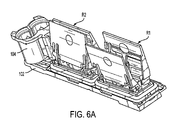
- FIG. 6A is a perspective view of the underside of the crown member showing the provision of separate pairs of regulator members which control the supply of ink into the separate chambers of the ink cartridge.
- FIG. 6B is an enlarged view of the arrangement shown in FIG. 6A showing the provision of a bladder between a pair regulator members and a spring which biases the pair of regulator members toward one and other.
- FIG. 7 is a perspective view of an exemplary valve seat which cooperates with a valve member carried on a pair of regulator members to permit passage of ink into a chamber of the ink cartridge.
- FIG. 8 is a perspective view showing the disposition of the two valve seats in a lower face of the crown along with over-molded rubber gaskets which seal the ink in respective chambers of the ink cartridge.
- FIG. 9 is a perspective close-up view showing details of the side walls which form part of ink transfer channels formed on the upper face of the crown.
- FIG. 10 is a perspective view showing details of an ink channel structure having a fitment that permits air to enter while preventing ink from escaping, and a leak test port which can be permanently sealed after successful testing for leaks.
- An exemplary embodiment of the invention has a dual-shroud or cap which is snapped into a dual-channel crown, that sits on a dual-chambered pen body.
- the shroud and crown deliver two different inks from the inkjet printer to the chambers in the pen body. Inks flow into the shroud, through separate channels in the crown, and to their respective chambers in the body of the pen under regulation by the dual/tandem regulators.
- This dual-chambered inkjet cartridge permits a plurality of inks to be dispensed on paper at a lower cost.
- one cartridge can be used to dispense two or more inks or other fluids, reducing cost and/or permitting more inks to be used in the same space in a printer.
- Separate ink from the cartridge allows automatic refill of ink into the cartridge.
- the printer can run for longer intervals with larger ink supplies before running out, and when ink does run out, only the ink container needs to be replaced, not the entire cartridge.
- self-refillable cartridges only contained one ink.
- Some of the features of the exemplary embodiments shown herein include, for example, on-axis/on-carriage regulation of two or more inks, regulation of two or more inks using internal regulator assemblies in separate chambers within the pen, transportation of two or more inks from a printer or other like printing device, through a fluid-interconnect system, to the chambers within the pen, and a system for delivering multiple off-axis/off-carriage ink supplies to one print head (e.g., one silicon die).
- one print head e.g., one silicon die
- FIG. 1 shows an exemplary embodiment of an ink cartridge 100 which includes multi-chambered pen body 101 , a crown 102 which sits on the pen body 101 in a manner which closes the open mouths of the chambers (see FIG. 2 ).
- the ink cartridge 100 further includes a shroud 104 which, in this example, is integral with the crown 102 and disposed at one end thereof.
- a cap or lid 106 is attached on the upper surface of the crown.
- the shroud 104 is such as to surround and enclose two elongate hollow members or needles 104 A which are configured to fit into the open ends of interconnecting tubes or conduits (not shown) so as to enable ink to be received from a printer (not shown) associated with the cartridge 100 .
- the shroud 104 is formed separately from the crown 102 and then connected thereto.
- shroud 104 is formed with a T-shaped slot 104 S which is configured to receive a T-shaped guide member 101 B which is integral with the pen body 101 .
- the needles 104 A are arranged to fluidly communicate with a first set of ink transfer ports 102 A 1 and 102 A 2 which are formed in one end of the crown 102 as best seen in FIG. 4 .
- These ports 102 A 1 and 102 A 2 respectively communicate with first and second ink transfer channels 102 TC 1 and 102 TC 2 .
- channel 102 TC 1 is longer than 102 TC 2 and extends to an ink transfer port 102 IN 1 which is located proximate an end of the crown that is distal from the end to which the shroud 104 is connected.
- Ink transfer port 102 IN 1 is configured to communicate with the first ink chamber 101 C 1 ( FIG. 1 ) which is formed in the pen body 101 , when the crown 102 is disposed on the pen body 101 .
- the second ink transfer channel 102 TC 2 is shorter than the first, leads to an ink transfer port 102 IN 2 which is configured to communicate with the second ink chamber 101 C 2 ( FIG. 2 ) in the pen body 101 .
- the second ink transfer channel 102 TC 2 leads around a leak test port 102 LTP 2 and terminates at the ink transfer port 102 IN 2 which is located between the leak test port 102 LTP 2 and an air vent fitment 102 AV 2 .
- Another air vent fitment 102 AV 1 is formed on a stepped portion which is located at one end of the crown 102 and thus located in the position just beyond the end of the first ink transfer channel 102 TC 1 and adjacent the ink transfer port 102 IN 1 .
- the channels 102 TC 1 , 102 TC 2 are carefully routed around the features on the upper face of the crown 102 including the leak test port 102 LTP 2 and fitment 102 AV 2 .
- the features are disposed between the channels so that the channel design is optimized to minimize the number of bends therein.
- Channel cross section may also be optimized for flow and available crown real estate.
- the fitments 102 AV 1 and 102 AV 2 are arranged to permit air to pass in both directions therethrough but prevent the passage of ink in either direction and thus prevent leakage of ink from the ink chambers 101 C 1 and 101 C 2 .
- These fitments l 02 AV 1 and 102 AV 2 are also associated with an arrangement that controls the supply of ink into the chambers 101 C 1 and 101 C 2 . This control will be explained herein later.
- the upper edges CE (see FIG. 9 ) of the channels 102 TC 1 and 102 TC 2 are arranged to extend about the upper face of the crown 102 to the degree that, when the cap 106 is attached (e.g., welded into place) on the crown 102 , the lower face of the cap 106 sealingly engages the upper edges CE and thus defines separate passages through which ink can flow.
- the cap 106 (see FIG. 1 ) is also provided with ports 106 AV 2 which correspond to the fitment 102 AV 1 , and with port 106 LTP 2 which corresponds with the leak test port 102 LTP 2 .
- the stepped portion of the crown 102 is, in this particular embodiment, such that the cap 106 leaves leak test port 102 LTP 1 and fitment 102 AV 1 , uncovered.
- leak test ports 102 LTP 1 and 102 LTP 2 are permanently sealed after the cartridge has been successfully tested for leaks.
- the lower face of the crown 102 is, as shown in FIG. 6 , provided with pairs of pivotal flap-like members which shall be referred to as regulators R 1 , R 2 .
- the regulators R 1 , R 2 are pivotally supported on webs or posts 102 W which are formed on the lower face of the crown 102 (see FIGS. 7 and 8 ).
- the flap-like regulators R 1 , R 2 are arranged to extend into the ink chambers 101 C 1 and 101 C 2 when the crown 102 is seated on the pen body 101 .
- Each pair of pivotal members which comprise the regulators R 1 , R 2 is provided with a valve member (not shown) which is configured to engage a structure, referred to herein as “volcano spout.”
- Each of these volcano spouts 102 VS 1 , 102 VS 2 are formed on, or otherwise fixed to the lower face of the crown 102 (see FIGS. 7 and 8 ) so as to form valve seats with which the valve members can engage and close off communication between the ink chambers 101 C 1 and 101 C 2 ( FIG. 2 ) and the ink transfer ports 102 IN 1 and 102 IN 2 respectively.
- the regulators R 1 , R 2 each respond to the amount of ink in the respective ink chambers and to move in a manner which brings a valve element into engagement with a corresponding volcano spout when the associated chamber is filled to a predetermined degree with fluid.
- the fitments 102 AV 1 and 102 AV 2 are arranged to allow air to pass therethrough, for example, into sealed bags or bladders which are respectively disposed in the first and second ink chambers 101 C 1 and 101 C 2 between the two flap-like members of each of regulators R 1 and R 2 .
- the pressure in the chambers momentarily decreases, and air is inducted through the fitments and into the respective sealed bags to return the chamber pressure to normal.
- each bag fills with air, it expands and forces regulator members apart.
- the regulators R 1 , R 2 therefore open the volcano spouts and allowing ink to flow through the ink ports into the pen chambers.
- the pressure in the respective ink chambers is increased back to nominal, causing the bags to collapse forcing back out through the fitments and allowing the regulators R 1 , R 2 to pivot toward one another and thus close the volcano spouts.
- a biasing spring is used in the manner depicted in FIG. 6B to bias the regulators toward one another as the bags therebetween deflate and thus move the valve elements toward and into contact with the respective volcano spout closing the same. This prevents the ink chambers 101 C 1 and 101 C 2 from overfilling.
- the lower face of the crown 102 is formed with two over-molded rubber gaskets 102 G 1 and 102 G 2 . These are best seen in FIGS. 7 and 8 .
Abstract
Description
Claims (10)
Priority Applications (2)
| Application Number | Priority Date | Filing Date | Title |
|---|---|---|---|
| US11/039,879 US7278720B2 (en) | 2005-01-24 | 2005-01-24 | Ink cartridge with multiple chambers aligned along an axial length |
| US11/848,446 US7771030B2 (en) | 2005-01-24 | 2007-08-31 | Ink cartridge with multiple chambers aligned along an axial length |
Applications Claiming Priority (1)
| Application Number | Priority Date | Filing Date | Title |
|---|---|---|---|
| US11/039,879 US7278720B2 (en) | 2005-01-24 | 2005-01-24 | Ink cartridge with multiple chambers aligned along an axial length |
Related Child Applications (1)
| Application Number | Title | Priority Date | Filing Date |
|---|---|---|---|
| US11/848,446 Continuation US7771030B2 (en) | 2005-01-24 | 2007-08-31 | Ink cartridge with multiple chambers aligned along an axial length |
Publications (2)
| Publication Number | Publication Date |
|---|---|
| US20060164481A1 US20060164481A1 (en) | 2006-07-27 |
| US7278720B2 true US7278720B2 (en) | 2007-10-09 |
Family
ID=36696331
Family Applications (2)
| Application Number | Title | Priority Date | Filing Date |
|---|---|---|---|
| US11/039,879 Active 2025-10-12 US7278720B2 (en) | 2005-01-24 | 2005-01-24 | Ink cartridge with multiple chambers aligned along an axial length |
| US11/848,446 Expired - Fee Related US7771030B2 (en) | 2005-01-24 | 2007-08-31 | Ink cartridge with multiple chambers aligned along an axial length |
Family Applications After (1)
| Application Number | Title | Priority Date | Filing Date |
|---|---|---|---|
| US11/848,446 Expired - Fee Related US7771030B2 (en) | 2005-01-24 | 2007-08-31 | Ink cartridge with multiple chambers aligned along an axial length |
Country Status (1)
| Country | Link |
|---|---|
| US (2) | US7278720B2 (en) |
Cited By (3)
| Publication number | Priority date | Publication date | Assignee | Title |
|---|---|---|---|---|
| US20070291089A1 (en) * | 2005-01-24 | 2007-12-20 | Paul Fishbein | Ink Cartridge |
| WO2010087839A1 (en) * | 2009-01-29 | 2010-08-05 | Hewlett-Packard Development Company, L.P. | Print cartridge air discharge |
| US9987852B2 (en) | 2014-01-30 | 2018-06-05 | Hewlett-Packard Development Company, L.P. | Tri-color ink cartridge housing |
Families Citing this family (6)
| Publication number | Priority date | Publication date | Assignee | Title |
|---|---|---|---|---|
| US7284848B2 (en) * | 2005-11-28 | 2007-10-23 | Brother Kogyo Kabushiki Kaisha | Ink cartridges |
| CN108472961B (en) | 2015-10-28 | 2021-05-04 | 惠普发展公司,有限责任合伙企业 | Printer ink cartridge with multiple back pressure chambers |
| CN111942027B (en) | 2018-07-13 | 2021-10-15 | 惠普发展公司,有限责任合伙企业 | Printing liquid supply device, printing liquid supply device assembly and interface structure |
| AU2018431743B2 (en) | 2018-07-13 | 2022-01-27 | Hewlett-Packard Development Company, L.P. | Print liquid supply |
| EP3687807B1 (en) | 2018-07-13 | 2022-12-21 | Hewlett-Packard Development Company, L.P. | Print liquid supply |
| MX2020010362A (en) | 2018-07-13 | 2020-10-19 | Hewlett Packard Development Co | Print liquid supply. |
Citations (18)
| Publication number | Priority date | Publication date | Assignee | Title |
|---|---|---|---|---|
| US5278584A (en) | 1992-04-02 | 1994-01-11 | Hewlett-Packard Company | Ink delivery system for an inkjet printhead |
| US5967045A (en) | 1998-10-20 | 1999-10-19 | Imation Corp. | Ink delivery pressure control |
| US5992990A (en) | 1996-10-24 | 1999-11-30 | Hewlett-Packard Company | Ink delivery system having an off-carriage pressure regulator |
| US6138076A (en) | 1996-10-31 | 2000-10-24 | Geoquest, A Division Of Schlumberger | Automatic non-artificially extended fault surface based horizon modeling system |
| US6183076B1 (en) * | 1992-04-02 | 2001-02-06 | Hewlett-Packard Company | Printer having multi-chamber print cartridges and off-carriage regulator |
| US6188417B1 (en) | 1994-10-31 | 2001-02-13 | Hewlett-Packard Company | Fluidic adapter for use with an inkjet print cartridge having an internal pressure regulator |
| US6247798B1 (en) | 1997-05-13 | 2001-06-19 | Hewlett-Packard Company | Ink compensated geometry for multi-chamber ink-jet printhead |
| US6270185B1 (en) | 1999-08-27 | 2001-08-07 | Hewlett-Packard Company | Very-high-ratio mixed resolution and biphod pens for low-cost fast bidirectional one-pass incremental printing |
| US6273560B1 (en) | 1994-10-31 | 2001-08-14 | Hewlett-Packard Company | Print cartridge coupling and reservoir assembly for use in an inkjet printing system with an off-axis ink supply |
| US6286950B1 (en) | 1998-04-29 | 2001-09-11 | Hewlett-Packard Company | Inkjet storage container sealing mechanism |
| US6290321B1 (en) | 1994-08-09 | 2001-09-18 | Encad, Inc. | Printer ink cartridge |
| US6332677B1 (en) | 1992-04-02 | 2001-12-25 | Hewlett-Packard Company | Stable substrate structure for a wide swath nozzle array in a high resolution inkjet printer |
| US6354694B1 (en) | 1997-03-05 | 2002-03-12 | Hewlett-Packard Company | Method and apparatus for improved ink-drop distribution in ink-jet printing |
| US6422693B2 (en) * | 1994-10-31 | 2002-07-23 | Hewlett-Packard Company | Ink interconnect between print cartridge and carriage |
| US20020196317A1 (en) * | 2000-01-05 | 2002-12-26 | Ram Santhanam | Ink-jet pen with two-part lid and techniques for filling |
| US6669319B2 (en) | 2001-07-16 | 2003-12-30 | Fuji Xerox Co., Ltd. | Ink Jet printer and printing method |
| US6685307B2 (en) * | 2000-12-22 | 2004-02-03 | Hewlett-Packard Development Company L.P. | Apparatus for providing ink to an ink jet print head |
| US20040085394A1 (en) * | 2002-10-30 | 2004-05-06 | Michael Martin | Fluid interconnect for printhead assembly |
Family Cites Families (8)
| Publication number | Priority date | Publication date | Assignee | Title |
|---|---|---|---|---|
| US5408256A (en) * | 1992-07-27 | 1995-04-18 | Repeat-O-Type Manufacturing Company, Inc. | Refillable color ink jet cartridge and method for making said cartridge |
| US6367918B1 (en) * | 1994-10-31 | 2002-04-09 | Hewlett-Packard Company | Unitary latching device for secure positioning of print cartridge during printing, priming and replenishment |
| GB2316037B (en) * | 1996-08-02 | 2000-03-22 | Seiko Epson Corp | Ink cartridge and a printing device using the ink cartridge |
| US6494630B2 (en) * | 1999-10-31 | 2002-12-17 | Hewlett-Packard Company | Datum structure for compact print cartridge |
| US6290348B1 (en) * | 2000-01-05 | 2001-09-18 | Hewlett-Packard Company | Techniques for providing ink-jet cartridges with a universal body structure |
| US6869166B2 (en) * | 2003-04-09 | 2005-03-22 | Joaquim Brugue | Multi-die fluid ejection apparatus and method |
| US7448734B2 (en) * | 2004-01-21 | 2008-11-11 | Silverbrook Research Pty Ltd | Inkjet printer cartridge with pagewidth printhead |
| US7278720B2 (en) * | 2005-01-24 | 2007-10-09 | Hewlett-Packard Develpoment Company, L.P. | Ink cartridge with multiple chambers aligned along an axial length |
-
2005
- 2005-01-24 US US11/039,879 patent/US7278720B2/en active Active
-
2007
- 2007-08-31 US US11/848,446 patent/US7771030B2/en not_active Expired - Fee Related
Patent Citations (18)
| Publication number | Priority date | Publication date | Assignee | Title |
|---|---|---|---|---|
| US6183076B1 (en) * | 1992-04-02 | 2001-02-06 | Hewlett-Packard Company | Printer having multi-chamber print cartridges and off-carriage regulator |
| US6332677B1 (en) | 1992-04-02 | 2001-12-25 | Hewlett-Packard Company | Stable substrate structure for a wide swath nozzle array in a high resolution inkjet printer |
| US5278584A (en) | 1992-04-02 | 1994-01-11 | Hewlett-Packard Company | Ink delivery system for an inkjet printhead |
| US6290321B1 (en) | 1994-08-09 | 2001-09-18 | Encad, Inc. | Printer ink cartridge |
| US6273560B1 (en) | 1994-10-31 | 2001-08-14 | Hewlett-Packard Company | Print cartridge coupling and reservoir assembly for use in an inkjet printing system with an off-axis ink supply |
| US6422693B2 (en) * | 1994-10-31 | 2002-07-23 | Hewlett-Packard Company | Ink interconnect between print cartridge and carriage |
| US6188417B1 (en) | 1994-10-31 | 2001-02-13 | Hewlett-Packard Company | Fluidic adapter for use with an inkjet print cartridge having an internal pressure regulator |
| US5992990A (en) | 1996-10-24 | 1999-11-30 | Hewlett-Packard Company | Ink delivery system having an off-carriage pressure regulator |
| US6138076A (en) | 1996-10-31 | 2000-10-24 | Geoquest, A Division Of Schlumberger | Automatic non-artificially extended fault surface based horizon modeling system |
| US6354694B1 (en) | 1997-03-05 | 2002-03-12 | Hewlett-Packard Company | Method and apparatus for improved ink-drop distribution in ink-jet printing |
| US6247798B1 (en) | 1997-05-13 | 2001-06-19 | Hewlett-Packard Company | Ink compensated geometry for multi-chamber ink-jet printhead |
| US6286950B1 (en) | 1998-04-29 | 2001-09-11 | Hewlett-Packard Company | Inkjet storage container sealing mechanism |
| US5967045A (en) | 1998-10-20 | 1999-10-19 | Imation Corp. | Ink delivery pressure control |
| US6270185B1 (en) | 1999-08-27 | 2001-08-07 | Hewlett-Packard Company | Very-high-ratio mixed resolution and biphod pens for low-cost fast bidirectional one-pass incremental printing |
| US20020196317A1 (en) * | 2000-01-05 | 2002-12-26 | Ram Santhanam | Ink-jet pen with two-part lid and techniques for filling |
| US6685307B2 (en) * | 2000-12-22 | 2004-02-03 | Hewlett-Packard Development Company L.P. | Apparatus for providing ink to an ink jet print head |
| US6669319B2 (en) | 2001-07-16 | 2003-12-30 | Fuji Xerox Co., Ltd. | Ink Jet printer and printing method |
| US20040085394A1 (en) * | 2002-10-30 | 2004-05-06 | Michael Martin | Fluid interconnect for printhead assembly |
Cited By (4)
| Publication number | Priority date | Publication date | Assignee | Title |
|---|---|---|---|---|
| US20070291089A1 (en) * | 2005-01-24 | 2007-12-20 | Paul Fishbein | Ink Cartridge |
| US7771030B2 (en) * | 2005-01-24 | 2010-08-10 | Hewlett-Packard Development Company, L.P. | Ink cartridge with multiple chambers aligned along an axial length |
| WO2010087839A1 (en) * | 2009-01-29 | 2010-08-05 | Hewlett-Packard Development Company, L.P. | Print cartridge air discharge |
| US9987852B2 (en) | 2014-01-30 | 2018-06-05 | Hewlett-Packard Development Company, L.P. | Tri-color ink cartridge housing |
Also Published As
| Publication number | Publication date |
|---|---|
| US7771030B2 (en) | 2010-08-10 |
| US20070291089A1 (en) | 2007-12-20 |
| US20060164481A1 (en) | 2006-07-27 |
Similar Documents
| Publication | Publication Date | Title |
|---|---|---|
| US7771030B2 (en) | Ink cartridge with multiple chambers aligned along an axial length | |
| US6068370A (en) | Fluidic delivery system with tubing and manifolding for an off-axis printing system | |
| AU2002254072B2 (en) | Dual serial pressure regulator for ink-jet printing | |
| USRE37874E1 (en) | Off-axis ink with supply with pressurized ink tube for preventing air ingestion | |
| US9669635B2 (en) | Attachment and attachment system | |
| JP4616425B2 (en) | Ink delivery system for inkjet printing system | |
| CN103600586B (en) | Liquid delivery system and liquid injection apparatus | |
| JP5777581B2 (en) | Inkjet recording device | |
| JP5978400B2 (en) | Liquid supply mechanism and printing apparatus | |
| JP3684572B2 (en) | Ink cartridge and ink jet recording apparatus using the same | |
| CN109572221A (en) | Liquid injection apparatus and liquid ejecting head | |
| JP4185578B2 (en) | Fluid adapter for inkjet print cartridge | |
| US8348397B2 (en) | Fluid height backpressure device in a system for supplying fluid to a printhead | |
| US20140362145A1 (en) | Liquid supply | |
| US20190143702A1 (en) | Liquid container | |
| JP3687517B2 (en) | Ink cartridge connection structure and ink jet recording apparatus using the same | |
| US20110012964A1 (en) | Fluid height backpressure system for supplying fluid to a printhead and backpressure device used therein | |
| US7284844B2 (en) | Air-driven delivery assembly | |
| US8256880B2 (en) | Fluid height backpressure device in a system for supplying fluid to a printhead | |
| JP2005306030A (en) | Attachment, attachment system, and liquid supplying device | |
| JP2000043286A (en) | Ink delivery system | |
| JP7434259B2 (en) | liquid refill system | |
| US9162468B2 (en) | Liquid supply | |
| EP0903238A2 (en) | Ink delivery system for ink-jet printer | |
| JP4550325B2 (en) | Inkjet recording device |
Legal Events
| Date | Code | Title | Description |
|---|---|---|---|
| AS | Assignment |
Owner name: HEWLETT-PACKARD DEVELOPMENT COMPANY, L.P., TEXAS Free format text: ASSIGNMENT OF ASSIGNORS INTEREST;ASSIGNORS:FISHBEIN, PAUL;BUTLER, BLAIR A.;SCHMID, GEOFFREY;AND OTHERS;REEL/FRAME:016495/0088 Effective date: 20050314 |
|
| STCF | Information on status: patent grant |
Free format text: PATENTED CASE |
|
| CC | Certificate of correction | ||
| FPAY | Fee payment |
Year of fee payment: 4 |
|
| FPAY | Fee payment |
Year of fee payment: 8 |
|
| MAFP | Maintenance fee payment |
Free format text: PAYMENT OF MAINTENANCE FEE, 12TH YEAR, LARGE ENTITY (ORIGINAL EVENT CODE: M1553); ENTITY STATUS OF PATENT OWNER: LARGE ENTITY Year of fee payment: 12 |