US7244357B2 - Pumps for filtration systems - Google Patents
Pumps for filtration systems Download PDFInfo
- Publication number
- US7244357B2 US7244357B2 US10/759,750 US75975004A US7244357B2 US 7244357 B2 US7244357 B2 US 7244357B2 US 75975004 A US75975004 A US 75975004A US 7244357 B2 US7244357 B2 US 7244357B2
- Authority
- US
- United States
- Prior art keywords
- retentate
- pressure
- piston
- membrane filtration
- feed
- Prior art date
- Legal status (The legal status is an assumption and is not a legal conclusion. Google has not performed a legal analysis and makes no representation as to the accuracy of the status listed.)
- Expired - Fee Related, expires
Links
Images


Classifications
-
- B—PERFORMING OPERATIONS; TRANSPORTING
- B01—PHYSICAL OR CHEMICAL PROCESSES OR APPARATUS IN GENERAL
- B01D—SEPARATION
- B01D61/00—Processes of separation using semi-permeable membranes, e.g. dialysis, osmosis or ultrafiltration; Apparatus, accessories or auxiliary operations specially adapted therefor
- B01D61/02—Reverse osmosis; Hyperfiltration ; Nanofiltration
- B01D61/04—Feed pretreatment
-
- B—PERFORMING OPERATIONS; TRANSPORTING
- B01—PHYSICAL OR CHEMICAL PROCESSES OR APPARATUS IN GENERAL
- B01D—SEPARATION
- B01D61/00—Processes of separation using semi-permeable membranes, e.g. dialysis, osmosis or ultrafiltration; Apparatus, accessories or auxiliary operations specially adapted therefor
- B01D61/02—Reverse osmosis; Hyperfiltration ; Nanofiltration
- B01D61/025—Reverse osmosis; Hyperfiltration
-
- B—PERFORMING OPERATIONS; TRANSPORTING
- B01—PHYSICAL OR CHEMICAL PROCESSES OR APPARATUS IN GENERAL
- B01D—SEPARATION
- B01D61/00—Processes of separation using semi-permeable membranes, e.g. dialysis, osmosis or ultrafiltration; Apparatus, accessories or auxiliary operations specially adapted therefor
- B01D61/02—Reverse osmosis; Hyperfiltration ; Nanofiltration
- B01D61/027—Nanofiltration
-
- B—PERFORMING OPERATIONS; TRANSPORTING
- B01—PHYSICAL OR CHEMICAL PROCESSES OR APPARATUS IN GENERAL
- B01D—SEPARATION
- B01D61/00—Processes of separation using semi-permeable membranes, e.g. dialysis, osmosis or ultrafiltration; Apparatus, accessories or auxiliary operations specially adapted therefor
- B01D61/02—Reverse osmosis; Hyperfiltration ; Nanofiltration
- B01D61/06—Energy recovery
-
- B—PERFORMING OPERATIONS; TRANSPORTING
- B01—PHYSICAL OR CHEMICAL PROCESSES OR APPARATUS IN GENERAL
- B01D—SEPARATION
- B01D61/00—Processes of separation using semi-permeable membranes, e.g. dialysis, osmosis or ultrafiltration; Apparatus, accessories or auxiliary operations specially adapted therefor
- B01D61/02—Reverse osmosis; Hyperfiltration ; Nanofiltration
- B01D61/08—Apparatus therefor
-
- B—PERFORMING OPERATIONS; TRANSPORTING
- B01—PHYSICAL OR CHEMICAL PROCESSES OR APPARATUS IN GENERAL
- B01D—SEPARATION
- B01D61/00—Processes of separation using semi-permeable membranes, e.g. dialysis, osmosis or ultrafiltration; Apparatus, accessories or auxiliary operations specially adapted therefor
- B01D61/02—Reverse osmosis; Hyperfiltration ; Nanofiltration
- B01D61/10—Accessories; Auxiliary operations
-
- B—PERFORMING OPERATIONS; TRANSPORTING
- B01—PHYSICAL OR CHEMICAL PROCESSES OR APPARATUS IN GENERAL
- B01D—SEPARATION
- B01D61/00—Processes of separation using semi-permeable membranes, e.g. dialysis, osmosis or ultrafiltration; Apparatus, accessories or auxiliary operations specially adapted therefor
- B01D61/02—Reverse osmosis; Hyperfiltration ; Nanofiltration
- B01D61/12—Controlling or regulating
-
- B—PERFORMING OPERATIONS; TRANSPORTING
- B01—PHYSICAL OR CHEMICAL PROCESSES OR APPARATUS IN GENERAL
- B01D—SEPARATION
- B01D61/00—Processes of separation using semi-permeable membranes, e.g. dialysis, osmosis or ultrafiltration; Apparatus, accessories or auxiliary operations specially adapted therefor
- B01D61/14—Ultrafiltration; Microfiltration
- B01D61/145—Ultrafiltration
-
- B—PERFORMING OPERATIONS; TRANSPORTING
- B01—PHYSICAL OR CHEMICAL PROCESSES OR APPARATUS IN GENERAL
- B01D—SEPARATION
- B01D61/00—Processes of separation using semi-permeable membranes, e.g. dialysis, osmosis or ultrafiltration; Apparatus, accessories or auxiliary operations specially adapted therefor
- B01D61/14—Ultrafiltration; Microfiltration
- B01D61/147—Microfiltration
-
- B—PERFORMING OPERATIONS; TRANSPORTING
- B01—PHYSICAL OR CHEMICAL PROCESSES OR APPARATUS IN GENERAL
- B01D—SEPARATION
- B01D63/00—Apparatus in general for separation processes using semi-permeable membranes
- B01D63/10—Spiral-wound membrane modules
-
- B—PERFORMING OPERATIONS; TRANSPORTING
- B01—PHYSICAL OR CHEMICAL PROCESSES OR APPARATUS IN GENERAL
- B01D—SEPARATION
- B01D63/00—Apparatus in general for separation processes using semi-permeable membranes
- B01D63/10—Spiral-wound membrane modules
- B01D63/107—Specific properties of the central tube or the permeate channel
-
- B—PERFORMING OPERATIONS; TRANSPORTING
- B01—PHYSICAL OR CHEMICAL PROCESSES OR APPARATUS IN GENERAL
- B01D—SEPARATION
- B01D65/00—Accessories or auxiliary operations, in general, for separation processes or apparatus using semi-permeable membranes
- B01D65/08—Prevention of membrane fouling or of concentration polarisation
-
- B—PERFORMING OPERATIONS; TRANSPORTING
- B01—PHYSICAL OR CHEMICAL PROCESSES OR APPARATUS IN GENERAL
- B01D—SEPARATION
- B01D67/00—Processes specially adapted for manufacturing semi-permeable membranes for separation processes or apparatus
- B01D67/0081—After-treatment of organic or inorganic membranes
- B01D67/0088—Physical treatment with compounds, e.g. swelling, coating or impregnation
-
- B—PERFORMING OPERATIONS; TRANSPORTING
- B01—PHYSICAL OR CHEMICAL PROCESSES OR APPARATUS IN GENERAL
- B01D—SEPARATION
- B01D69/00—Semi-permeable membranes for separation processes or apparatus characterised by their form, structure or properties; Manufacturing processes specially adapted therefor
- B01D69/02—Semi-permeable membranes for separation processes or apparatus characterised by their form, structure or properties; Manufacturing processes specially adapted therefor characterised by their properties
-
- B—PERFORMING OPERATIONS; TRANSPORTING
- B01—PHYSICAL OR CHEMICAL PROCESSES OR APPARATUS IN GENERAL
- B01D—SEPARATION
- B01D69/00—Semi-permeable membranes for separation processes or apparatus characterised by their form, structure or properties; Manufacturing processes specially adapted therefor
- B01D69/14—Dynamic membranes
- B01D69/141—Heterogeneous membranes, e.g. containing dispersed material; Mixed matrix membranes
-
- B—PERFORMING OPERATIONS; TRANSPORTING
- B29—WORKING OF PLASTICS; WORKING OF SUBSTANCES IN A PLASTIC STATE IN GENERAL
- B29C—SHAPING OR JOINING OF PLASTICS; SHAPING OF MATERIAL IN A PLASTIC STATE, NOT OTHERWISE PROVIDED FOR; AFTER-TREATMENT OF THE SHAPED PRODUCTS, e.g. REPAIRING
- B29C41/00—Shaping by coating a mould, core or other substrate, i.e. by depositing material and stripping-off the shaped article; Apparatus therefor
- B29C41/02—Shaping by coating a mould, core or other substrate, i.e. by depositing material and stripping-off the shaped article; Apparatus therefor for making articles of definite length, i.e. discrete articles
- B29C41/20—Shaping by coating a mould, core or other substrate, i.e. by depositing material and stripping-off the shaped article; Apparatus therefor for making articles of definite length, i.e. discrete articles incorporating preformed parts or layers, e.g. moulding inserts or for coating articles
-
- B—PERFORMING OPERATIONS; TRANSPORTING
- B41—PRINTING; LINING MACHINES; TYPEWRITERS; STAMPS
- B41J—TYPEWRITERS; SELECTIVE PRINTING MECHANISMS, i.e. MECHANISMS PRINTING OTHERWISE THAN FROM A FORME; CORRECTION OF TYPOGRAPHICAL ERRORS
- B41J2/00—Typewriters or selective printing mechanisms characterised by the printing or marking process for which they are designed
- B41J2/005—Typewriters or selective printing mechanisms characterised by the printing or marking process for which they are designed characterised by bringing liquid or particles selectively into contact with a printing material
- B41J2/01—Ink jet
-
- B—PERFORMING OPERATIONS; TRANSPORTING
- B41—PRINTING; LINING MACHINES; TYPEWRITERS; STAMPS
- B41J—TYPEWRITERS; SELECTIVE PRINTING MECHANISMS, i.e. MECHANISMS PRINTING OTHERWISE THAN FROM A FORME; CORRECTION OF TYPOGRAPHICAL ERRORS
- B41J3/00—Typewriters or selective printing or marking mechanisms characterised by the purpose for which they are constructed
- B41J3/407—Typewriters or selective printing or marking mechanisms characterised by the purpose for which they are constructed for marking on special material
-
- C—CHEMISTRY; METALLURGY
- C02—TREATMENT OF WATER, WASTE WATER, SEWAGE, OR SLUDGE
- C02F—TREATMENT OF WATER, WASTE WATER, SEWAGE, OR SLUDGE
- C02F1/00—Treatment of water, waste water, or sewage
- C02F1/46—Treatment of water, waste water, or sewage by electrochemical methods
- C02F1/461—Treatment of water, waste water, or sewage by electrochemical methods by electrolysis
- C02F1/46104—Devices therefor; Their operating or servicing
-
- C—CHEMISTRY; METALLURGY
- C02—TREATMENT OF WATER, WASTE WATER, SEWAGE, OR SLUDGE
- C02F—TREATMENT OF WATER, WASTE WATER, SEWAGE, OR SLUDGE
- C02F1/00—Treatment of water, waste water, or sewage
- C02F1/46—Treatment of water, waste water, or sewage by electrochemical methods
- C02F1/461—Treatment of water, waste water, or sewage by electrochemical methods by electrolysis
- C02F1/467—Treatment of water, waste water, or sewage by electrochemical methods by electrolysis by electrochemical disinfection; by electrooxydation or by electroreduction
- C02F1/4672—Treatment of water, waste water, or sewage by electrochemical methods by electrolysis by electrochemical disinfection; by electrooxydation or by electroreduction by electrooxydation
- C02F1/4674—Treatment of water, waste water, or sewage by electrochemical methods by electrolysis by electrochemical disinfection; by electrooxydation or by electroreduction by electrooxydation with halogen or compound of halogens, e.g. chlorine, bromine
-
- C—CHEMISTRY; METALLURGY
- C02—TREATMENT OF WATER, WASTE WATER, SEWAGE, OR SLUDGE
- C02F—TREATMENT OF WATER, WASTE WATER, SEWAGE, OR SLUDGE
- C02F9/00—Multistage treatment of water, waste water or sewage
- C02F9/20—Portable or detachable small-scale multistage treatment devices, e.g. point of use or laboratory water purification systems
-
- F—MECHANICAL ENGINEERING; LIGHTING; HEATING; WEAPONS; BLASTING
- F04—POSITIVE - DISPLACEMENT MACHINES FOR LIQUIDS; PUMPS FOR LIQUIDS OR ELASTIC FLUIDS
- F04B—POSITIVE-DISPLACEMENT MACHINES FOR LIQUIDS; PUMPS
- F04B43/00—Machines, pumps, or pumping installations having flexible working members
- F04B43/02—Machines, pumps, or pumping installations having flexible working members having plate-like flexible members, e.g. diaphragms
- F04B43/04—Pumps having electric drive
-
- F—MECHANICAL ENGINEERING; LIGHTING; HEATING; WEAPONS; BLASTING
- F04—POSITIVE - DISPLACEMENT MACHINES FOR LIQUIDS; PUMPS FOR LIQUIDS OR ELASTIC FLUIDS
- F04B—POSITIVE-DISPLACEMENT MACHINES FOR LIQUIDS; PUMPS
- F04B43/00—Machines, pumps, or pumping installations having flexible working members
- F04B43/02—Machines, pumps, or pumping installations having flexible working members having plate-like flexible members, e.g. diaphragms
- F04B43/06—Pumps having fluid drive
- F04B43/073—Pumps having fluid drive the actuating fluid being controlled by at least one valve
-
- F—MECHANICAL ENGINEERING; LIGHTING; HEATING; WEAPONS; BLASTING
- F04—POSITIVE - DISPLACEMENT MACHINES FOR LIQUIDS; PUMPS FOR LIQUIDS OR ELASTIC FLUIDS
- F04B—POSITIVE-DISPLACEMENT MACHINES FOR LIQUIDS; PUMPS
- F04B9/00—Piston machines or pumps characterised by the driving or driven means to or from their working members
- F04B9/08—Piston machines or pumps characterised by the driving or driven means to or from their working members the means being fluid
- F04B9/10—Piston machines or pumps characterised by the driving or driven means to or from their working members the means being fluid the fluid being liquid
- F04B9/103—Piston machines or pumps characterised by the driving or driven means to or from their working members the means being fluid the fluid being liquid having only one pumping chamber
- F04B9/107—Piston machines or pumps characterised by the driving or driven means to or from their working members the means being fluid the fluid being liquid having only one pumping chamber rectilinear movement of the pumping member in the working direction being obtained by a single-acting liquid motor, e.g. actuated in the other direction by gravity or a spring
-
- F—MECHANICAL ENGINEERING; LIGHTING; HEATING; WEAPONS; BLASTING
- F04—POSITIVE - DISPLACEMENT MACHINES FOR LIQUIDS; PUMPS FOR LIQUIDS OR ELASTIC FLUIDS
- F04B—POSITIVE-DISPLACEMENT MACHINES FOR LIQUIDS; PUMPS
- F04B9/00—Piston machines or pumps characterised by the driving or driven means to or from their working members
- F04B9/14—Pumps characterised by muscle-power operation
-
- B—PERFORMING OPERATIONS; TRANSPORTING
- B01—PHYSICAL OR CHEMICAL PROCESSES OR APPARATUS IN GENERAL
- B01D—SEPARATION
- B01D2311/00—Details relating to membrane separation process operations and control
- B01D2311/04—Specific process operations in the feed stream; Feed pretreatment
-
- B—PERFORMING OPERATIONS; TRANSPORTING
- B01—PHYSICAL OR CHEMICAL PROCESSES OR APPARATUS IN GENERAL
- B01D—SEPARATION
- B01D2321/00—Details relating to membrane cleaning, regeneration, sterilization or to the prevention of fouling
- B01D2321/04—Backflushing
-
- B—PERFORMING OPERATIONS; TRANSPORTING
- B01—PHYSICAL OR CHEMICAL PROCESSES OR APPARATUS IN GENERAL
- B01D—SEPARATION
- B01D2321/00—Details relating to membrane cleaning, regeneration, sterilization or to the prevention of fouling
- B01D2321/20—By influencing the flow
- B01D2321/2008—By influencing the flow statically
- B01D2321/2016—Static mixers; Turbulence generators
-
- C—CHEMISTRY; METALLURGY
- C02—TREATMENT OF WATER, WASTE WATER, SEWAGE, OR SLUDGE
- C02F—TREATMENT OF WATER, WASTE WATER, SEWAGE, OR SLUDGE
- C02F1/00—Treatment of water, waste water, or sewage
- C02F1/001—Processes for the treatment of water whereby the filtration technique is of importance
-
- C—CHEMISTRY; METALLURGY
- C02—TREATMENT OF WATER, WASTE WATER, SEWAGE, OR SLUDGE
- C02F—TREATMENT OF WATER, WASTE WATER, SEWAGE, OR SLUDGE
- C02F1/00—Treatment of water, waste water, or sewage
- C02F1/44—Treatment of water, waste water, or sewage by dialysis, osmosis or reverse osmosis
-
- C—CHEMISTRY; METALLURGY
- C02—TREATMENT OF WATER, WASTE WATER, SEWAGE, OR SLUDGE
- C02F—TREATMENT OF WATER, WASTE WATER, SEWAGE, OR SLUDGE
- C02F1/00—Treatment of water, waste water, or sewage
- C02F1/44—Treatment of water, waste water, or sewage by dialysis, osmosis or reverse osmosis
- C02F1/441—Treatment of water, waste water, or sewage by dialysis, osmosis or reverse osmosis by reverse osmosis
-
- C—CHEMISTRY; METALLURGY
- C02—TREATMENT OF WATER, WASTE WATER, SEWAGE, OR SLUDGE
- C02F—TREATMENT OF WATER, WASTE WATER, SEWAGE, OR SLUDGE
- C02F1/00—Treatment of water, waste water, or sewage
- C02F1/46—Treatment of water, waste water, or sewage by electrochemical methods
- C02F1/461—Treatment of water, waste water, or sewage by electrochemical methods by electrolysis
- C02F1/46104—Devices therefor; Their operating or servicing
- C02F1/46109—Electrodes
- C02F2001/46119—Cleaning the electrodes
-
- C—CHEMISTRY; METALLURGY
- C02—TREATMENT OF WATER, WASTE WATER, SEWAGE, OR SLUDGE
- C02F—TREATMENT OF WATER, WASTE WATER, SEWAGE, OR SLUDGE
- C02F1/00—Treatment of water, waste water, or sewage
- C02F1/46—Treatment of water, waste water, or sewage by electrochemical methods
- C02F1/461—Treatment of water, waste water, or sewage by electrochemical methods by electrolysis
- C02F1/46104—Devices therefor; Their operating or servicing
- C02F1/46109—Electrodes
- C02F2001/46128—Bipolar electrodes
-
- C—CHEMISTRY; METALLURGY
- C02—TREATMENT OF WATER, WASTE WATER, SEWAGE, OR SLUDGE
- C02F—TREATMENT OF WATER, WASTE WATER, SEWAGE, OR SLUDGE
- C02F1/00—Treatment of water, waste water, or sewage
- C02F1/46—Treatment of water, waste water, or sewage by electrochemical methods
- C02F1/461—Treatment of water, waste water, or sewage by electrochemical methods by electrolysis
- C02F1/46104—Devices therefor; Their operating or servicing
- C02F1/46109—Electrodes
- C02F2001/46133—Electrodes characterised by the material
- C02F2001/46138—Electrodes comprising a substrate and a coating
- C02F2001/46142—Catalytic coating
-
- C—CHEMISTRY; METALLURGY
- C02—TREATMENT OF WATER, WASTE WATER, SEWAGE, OR SLUDGE
- C02F—TREATMENT OF WATER, WASTE WATER, SEWAGE, OR SLUDGE
- C02F2103/00—Nature of the water, waste water, sewage or sludge to be treated
- C02F2103/08—Seawater, e.g. for desalination
-
- C—CHEMISTRY; METALLURGY
- C02—TREATMENT OF WATER, WASTE WATER, SEWAGE, OR SLUDGE
- C02F—TREATMENT OF WATER, WASTE WATER, SEWAGE, OR SLUDGE
- C02F2201/00—Apparatus for treatment of water, waste water or sewage
- C02F2201/46—Apparatus for electrochemical processes
- C02F2201/461—Electrolysis apparatus
- C02F2201/46105—Details relating to the electrolytic devices
- C02F2201/4611—Fluid flow
-
- C—CHEMISTRY; METALLURGY
- C02—TREATMENT OF WATER, WASTE WATER, SEWAGE, OR SLUDGE
- C02F—TREATMENT OF WATER, WASTE WATER, SEWAGE, OR SLUDGE
- C02F2201/00—Apparatus for treatment of water, waste water or sewage
- C02F2201/46—Apparatus for electrochemical processes
- C02F2201/461—Electrolysis apparatus
- C02F2201/46105—Details relating to the electrolytic devices
- C02F2201/4612—Controlling or monitoring
- C02F2201/4615—Time
-
- C—CHEMISTRY; METALLURGY
- C02—TREATMENT OF WATER, WASTE WATER, SEWAGE, OR SLUDGE
- C02F—TREATMENT OF WATER, WASTE WATER, SEWAGE, OR SLUDGE
- C02F2201/00—Apparatus for treatment of water, waste water or sewage
- C02F2201/46—Apparatus for electrochemical processes
- C02F2201/461—Electrolysis apparatus
- C02F2201/46105—Details relating to the electrolytic devices
- C02F2201/4616—Power supply
- C02F2201/46165—Special power supply, e.g. solar energy or batteries
-
- C—CHEMISTRY; METALLURGY
- C02—TREATMENT OF WATER, WASTE WATER, SEWAGE, OR SLUDGE
- C02F—TREATMENT OF WATER, WASTE WATER, SEWAGE, OR SLUDGE
- C02F2201/00—Apparatus for treatment of water, waste water or sewage
- C02F2201/46—Apparatus for electrochemical processes
- C02F2201/461—Electrolysis apparatus
- C02F2201/46105—Details relating to the electrolytic devices
- C02F2201/4618—Supplying or removing reactants or electrolyte
-
- C—CHEMISTRY; METALLURGY
- C02—TREATMENT OF WATER, WASTE WATER, SEWAGE, OR SLUDGE
- C02F—TREATMENT OF WATER, WASTE WATER, SEWAGE, OR SLUDGE
- C02F2209/00—Controlling or monitoring parameters in water treatment
- C02F2209/04—Oxidation reduction potential [ORP]
-
- C—CHEMISTRY; METALLURGY
- C02—TREATMENT OF WATER, WASTE WATER, SEWAGE, OR SLUDGE
- C02F—TREATMENT OF WATER, WASTE WATER, SEWAGE, OR SLUDGE
- C02F2209/00—Controlling or monitoring parameters in water treatment
- C02F2209/10—Solids, e.g. total solids [TS], total suspended solids [TSS] or volatile solids [VS]
-
- C—CHEMISTRY; METALLURGY
- C02—TREATMENT OF WATER, WASTE WATER, SEWAGE, OR SLUDGE
- C02F—TREATMENT OF WATER, WASTE WATER, SEWAGE, OR SLUDGE
- C02F2303/00—Specific treatment goals
- C02F2303/04—Disinfection
-
- C—CHEMISTRY; METALLURGY
- C02—TREATMENT OF WATER, WASTE WATER, SEWAGE, OR SLUDGE
- C02F—TREATMENT OF WATER, WASTE WATER, SEWAGE, OR SLUDGE
- C02F9/00—Multistage treatment of water, waste water or sewage
-
- Y—GENERAL TAGGING OF NEW TECHNOLOGICAL DEVELOPMENTS; GENERAL TAGGING OF CROSS-SECTIONAL TECHNOLOGIES SPANNING OVER SEVERAL SECTIONS OF THE IPC; TECHNICAL SUBJECTS COVERED BY FORMER USPC CROSS-REFERENCE ART COLLECTIONS [XRACs] AND DIGESTS
- Y02—TECHNOLOGIES OR APPLICATIONS FOR MITIGATION OR ADAPTATION AGAINST CLIMATE CHANGE
- Y02A—TECHNOLOGIES FOR ADAPTATION TO CLIMATE CHANGE
- Y02A20/00—Water conservation; Efficient water supply; Efficient water use
- Y02A20/124—Water desalination
- Y02A20/131—Reverse-osmosis
-
- Y—GENERAL TAGGING OF NEW TECHNOLOGICAL DEVELOPMENTS; GENERAL TAGGING OF CROSS-SECTIONAL TECHNOLOGIES SPANNING OVER SEVERAL SECTIONS OF THE IPC; TECHNICAL SUBJECTS COVERED BY FORMER USPC CROSS-REFERENCE ART COLLECTIONS [XRACs] AND DIGESTS
- Y02—TECHNOLOGIES OR APPLICATIONS FOR MITIGATION OR ADAPTATION AGAINST CLIMATE CHANGE
- Y02A—TECHNOLOGIES FOR ADAPTATION TO CLIMATE CHANGE
- Y02A20/00—Water conservation; Efficient water supply; Efficient water use
- Y02A20/124—Water desalination
- Y02A20/138—Water desalination using renewable energy
- Y02A20/144—Wave energy
-
- Y—GENERAL TAGGING OF NEW TECHNOLOGICAL DEVELOPMENTS; GENERAL TAGGING OF CROSS-SECTIONAL TECHNOLOGIES SPANNING OVER SEVERAL SECTIONS OF THE IPC; TECHNICAL SUBJECTS COVERED BY FORMER USPC CROSS-REFERENCE ART COLLECTIONS [XRACs] AND DIGESTS
- Y02—TECHNOLOGIES OR APPLICATIONS FOR MITIGATION OR ADAPTATION AGAINST CLIMATE CHANGE
- Y02P—CLIMATE CHANGE MITIGATION TECHNOLOGIES IN THE PRODUCTION OR PROCESSING OF GOODS
- Y02P70/00—Climate change mitigation technologies in the production process for final industrial or consumer products
- Y02P70/10—Greenhouse gas [GHG] capture, material saving, heat recovery or other energy efficient measures, e.g. motor control, characterised by manufacturing processes, e.g. for rolling metal or metal working
Definitions
- the present invention relates to removing particulate and dissolved solids from water by spiral wrapped membrane elements utilizing a dual diaphragm pump system that preferably incorporates pressure recovery, pulsing, fixed recovery (ratio of permeate to feed), and thin feed spacer spiral wrapped membrane elements.
- the maximum benefit of the system is achieved when reverse osmosis (“RO”) is utilized as the membrane technology due to the high pressures inherent in RO membrane processes.
- RO reverse osmosis
- the system of the present invention is also effective on microfiltration, ultrafiltration, nanofiltration, and other membrane systems. More particularly the present invention relates to alternative means to increase the production of potable water per unit size of membrane element and to reduce the energy cost per unit volume of water treated.
- the present invention further relates to a reverse osmosis hand held pump with pressure recovery and in-line components for easy fabrication.
- TDS total dissolved solids
- water filtration must include the capability for both conventional filtration as well as desalination.
- Conventional filtration can remove particulates that cause turbidity such as dirt, silt, sand, and larger organisms such as Giardia and Cryptosporidium.
- Reverse osmosis (“RO”) technology must also be included to remove ions from such sources as sea water.
- RO Reverse osmosis
- the system At sea water concentrations of 35,000 milligrams per liter (mg/L), the system must be effective enough to remove ions to levels less than 1000 mg/L.
- sodium and chloride are the two ions of concern in sea water, the system must be able to remove other ions as well. All of these ions are collectively known as TDS.
- U.S. Pat. No. RE 32,144, to Keefer, entitled “Reverse Osmosis Method and Apparatus,” discloses a pump mechanism with pressure recovery and accumulator for reverse osmosis. The mechanism does not incorporate an efficient pressure relief and retentate discharge mechanism integral to the piston and rod assembly.
- U.S. Pat. No. 5,496,466, to Gray discloses a portable water purification system with a double piston pump comprising a feed water piston in a feed water cylinder, a concentrate pumping section for removing concentrate from concentrate output, and a concentrate pumping section including a concentrate cylinder and piston wherein the pistons move in opposite axially directions. Gray does not teach differential pressure control or use of a spring or other mechanism for storing energy to average out the forces of the respective strokes. Further, Gray teaches use of a two-piston system only.
- U.S. Pat. No. 5,503,736, to Schoenmeyr discloses a booster pump for a reverse osmosis water purification system wherein the pump has a spring return piston stroked by the pressure of feedwater and a pair of solenoid control valves (controlled by a piston position detector switch) that control the flow of feedwater into and out of the pump to move the piston between stroke and return positions.
- the Schoenmeyr patent while disclosing a single piston, employs a two-headed piston with solenoid control valves and a control circuit system, unlike the differential pressure activated valve of the present invention.
- Additional tangentially related prior art includes: U.S. Pat. No. 5,589,066, to Gray; U.S. Pat. No. 5,865,980 to Patapoff et al.; U.S. Pat. No. 3,966,364, to Bachle et al.; U.S. Pat. No. 5,531,887, to Miers; U.S. Pat. No. 4,740,301, to Lopez; and U.S. Pat. No. 3,830,372, to Manjikian.
- the present invention is of a pumping apparatus and method comprising: a dual head pump comprising a primary feed head comprising a feed diaphragm and a secondary retentate head comprising a retentate diaphragm; pumping fluid to at least one membrane surface; transferring force from the retentate diaphragm to the feed diaphragm to recover energy; providing a fixed recovery via the two heads; and imparting a pulsing pressure wave on the membrane surface.
- pumping fluid comprises providing feed fluid to a reverse osmosis membrane, preferably with at least one thin feed spacer element, and most preferably with at least one spiral wrapped element.
- Differential pressure is provided by a dual activated valve, pulsing is preferably hydraulic, and a plurality of membrane surfaces are provided, preferably wherein the spacing is reduced between the membrane surfaces to improve diffusion.
- the present invention is also of a filtration system which provides an optimized pulsed fluid flow to a filtration element.
- the system comprises a pump, preferably a diaphragm pump, which preferably comprises a primary feed head and a secondary retentate head comprising different swept volumes.
- the heads are preferably connected either mechanically or hydraulically, wherein a force on the retentate head offsets the pumping force on the feed head.
- the filtration system preferably comprises a differential pressure activated valve, which seals the discharge port of the retentate head when the feed pressure exceeds the retentate pressure. The connection between the heads and the valve provide a pressure recovery to the system, reducing the energy required to operate the system.
- the filtration element is preferably a reverse osmosis element, preferably comprising a spiral wrapped element which comprises at least one membrane and at least one thin feed spacer, which preferably comprises a plastic web mesh.
- the spacer is preferably less than about 0.025 inches thick, and more preferably less than about 0.011 inches thick.
- the filtration system preferably comprises automatic and/or manual controls to vary parameters of the system to optimize the permeate quality, flow rate, and system energy requirements.
- the parameters are preferably pulse frequency and pulse amplitude.
- the system optionally comprises at least one quality measurement device, including but not limited to a flow meter, conductivity meter, and/or ammeter, and optionally comprises a feedback loop to vary the parameters.
- the present invention is also of a method for filtering a substance comprising the steps of providing at least one filtration element; providing a pump which pumps a pulsed flow of the substance to the filtration element; and varying at least one parameter of the pulsed flow to optimize a desired characteristic of permeate filtered by the filtration element and the pump.
- the pump is preferably a dual head diaphragm pump in which the heads are connected in order to provide pressure recovery, thereby reducing the energy required to filter the substance.
- the method preferably comprises the step of sealing a discharge port of a retentate head when a feed pressure exceeds a retentate pressure, preferably using a differential pressure activated valve.
- the filtration element is preferably a reverse osmosis element, preferably comprising a spiral wrapped element which comprises at least one membrane and at least one thin feed spacer, which preferably comprises a plastic web mesh.
- the step of varying at least one parameter of the pulsed flow preferably comprises varying the pulse frequency and the pulse amplitude, and preferably further comprises measuring a desired characteristic of permeate, including but not limited to the permeate flow rate, the total dissolved solids in the permeate, and the amperage load on the pump.
- the method optionally comprises providing a feedback loop to automatically vary the parameter of the pulsed flow, thereby optimizing the desired characteristic of the permeate and pump.
- the present invention is additionally of a pressure recovery filtration system comprising a dual head pump comprising a primary feed head, a secondary retentate head and a connection between the two heads; a filtration element; and a hydraulically actuated differential pressure activated valve.
- the heads preferably comprise diaphragms.
- the connection is preferably mechanical, optionally comprising a shaft, or alternatively hydraulic.
- the force on the secondary retentate head preferably offsets the force on the primary feed head.
- the valve preferably seals the discharge port of said retentate head when a feed pressure exceeds a retentate pressure, and preferably comprises an inlet port connected to said retentate head and an inlet port connected to said feed head.
- the valve preferably actuates according to a relative pressure difference between said inlet ports.
- the present invention is further of a membrane filtration system comprising a piston which separates a feed chamber from a retentate chamber; a membrane filtration element; and a differential pressure activated (DPA) valve which controls the retentate discharge; wherein pressure recovery is provided by a pressure difference between the feed chamber and the retentate chamber acting on the piston.
- the pressure recovery is preferably significant enough to enable manual pumping of the piston, preferably at a recovery level of about fifty percent.
- the DPA valve is preferably hydraulically operated, with its operation determined by the relative pressure in the feed chamber and the retentate chamber, so that it operates automatically in accordance with pumping of the piston.
- the piston preferably comprises a piston shaft, the cross-sectional area of which determines the recovery ratio of the membrane filtration element.
- the piston shaft is preferably easily replaced, thereby enabling rapid change of the recovery ratio.
- the system preferably comprises a pressure relief valve.
- the membrane filtration system preferably comprises a single cylinder and has a diameter of less than approximately four inches, and more preferably less than approximately two inches.
- the system preferably has a length of less than approximately twenty-four inches, and more preferably less than approximately fifteen inches.
- the system preferably weighs less than five pounds, and more preferably less than three pounds.
- the membrane filtration element preferably comprises a reverse osmosis element, which preferably comprises a spiral wrapped element preferably comprising at least one membrane and at least one thin feed spacer.
- the spacer optionally comprises a plastic web mesh and is preferably less than approximately 0.025 inches thick, and more preferably less than approximately 0.011 inches thick.
- the thin feed spacer provides for a reduction in an amount of total dissolved solids at a surface of said membrane.
- the invention is also of a method of filtering a substance comprising the steps of pumping the substance with a piston, wherein the piston separates a feed chamber and a retentate chamber passing the substance through at least one membrane filtration element, preferably a reverse osmosis filtration element, thereby separating the substance into permeate and retentate; and discharging the retentate using a differential pressure activated (DPA) valve.
- DPA differential pressure activated
- the method preferably comprises operating the DPA valve hydraulically, preferably according to the relative pressure in the feed chamber and the retentate chamber. This operation is preferably automatic as the substance is pumped.
- the method further comprises utilizing a pressure difference between the feed chamber and the retentate chamber acting on the piston to reduce the force necessary to pump the substance, preferably to a level that enables manual operation of the system.
- a primary object of the present invention is to provide an improved filtration system for TDS reduction that provides potable water.
- Another object of the present invention is to provide an improved filtration system that is compact in size for one person to easily carry.
- a further object of the present invention is to provide an improved filtration system that can be operated purely with manual power as the only energy source.
- a primary advantage of the present invention is a pressure recovery feature in the pump that utilizes a simplified valve mechanism for retentate discharge.
- Another advantage of the apparatus is a pulsing mechanism in the pump that minimizes polarization concentration in the RO membrane thereby significantly reducing the applied pressure and improving the permeate flux produced for a given amount of power applied to the pump.
- FIG. 1 is a block diagram of the dual head pump filtration system of the present invention.
- FIG. 2 is a block diagram of the in-line pump filtration system of the present invention.
- the present invention is of a motor driven dual headed pump that incorporates a differential pressure activated (“DPA”) valve to provide a system that incorporates some or all of the innovations discussed previously.
- High Total Dissolved Solids (“TDS”) feed water e.g., seawater or brackish water
- TDS High Total Dissolved Solids
- the primary head of the pump is the larger of the two pump heads.
- Check valves on the inlet and exit of the pump head force water to be directed in one direction only through the pump head.
- As feed water discharges through primary pump head 28 ( FIG. 1 ) the feed water enters the feed end of the RO element housing. Water passes longitudinally through the RO element.
- the remaining water is higher TDS concentration (relative to the TDS of the feed water) that is retentate discharge from the RO element.
- the retentate is directed to the second, smaller diaphragm pump head.
- the ratio of the sizes of the pump heads explicitly defines the recovery of the RO system. With the smaller pump head being, e.g., 70 percent, of the volume of the primary pump head, the recovery of the system is approximately 30 percent. In other words, 30 percent of the feed volume is forced through the membranes of the RO element, thereby producing a permeate volume that is 30 percent of the feed.
- Various recovery ratios may be used depending upon the configuration of the system, and the fluid being treated. This feature addresses a first benefit of the invention, namely, enhanced recovery.
- Incorporating RO elements in the system with a thin feed spacer provide additional capacity to the system.
- the capacity of an existing RO plant is increased significantly by simply replacing existing technology RO elements with the thin feed spacer elements, and then adding the dual diaphragm pump system to provide the benefits of that system.
- Diaphragm pumps produce an inherent pulse to the fluid flow stream. This is by virtue of the reciprocal motion of the pump stroke mechanism.
- the stroke of the pump is controlled by an adjustable eccentric mechanism within the gear housing of the pump. This is usually controlled by a control knob or motor drive on the exterior of the pump.
- the frequency of the pump is controlled by the speed of the drive motor on the pump.
- Most diaphragm pumps manufactured today can be driven by a variable speed motor. This combination of stroke length and speed control allows variability of all key operational parameters that are important to optimizing the flow characteristics within the RO element.
- the stroke length and frequency are electronically optimized, or tuned, so that the optimal stroke and frequency are established for the RO element size and hydraulic system in question. The optimum conditions are achieved when the torque (or load) on the motor is minimized at the rated flow rate of the membrane element. This feature addresses the benefits from fluid flow pulsing.
- the feed pressure to the RO element is roughly equal to the retentate (or discharge) pressure from the RO element.
- flow through the feed spacer in the RO element is zero.
- there is no pressure drop across the element This means that the same pressure is applied on the large diaphragm pump head as there is on the small diaphragm pump head.
- the net working force on the pump is equal to the value of the recovery of the RO element.
- the force generated by the small pump head 70 percent offsets the force on the large head (100 percent) so that the net force required to operate the system is 30 percent. This is defined as pressure recovery.
- the energy required to operate the RO system is 30 percent of that required to operate a system that is comprised of one diaphragm. Indeed, conventional RO plants use high pressure pumps to provide the feed pressure for the RO elements, with no attempts to utilize pressure recovery. This feature alone can save 70 percent of the energy required to operate an RO plant.
- the benefits of diffusion may be offset by pulsing.
- the system integrates any or all of five features, or combinations thereof, of membrane technology for water treatment.
- the five features comprise the use of: (1) thin feed spacer spiral wrapped elements; (2) enhanced recovery (ratio of feed to permeate); (3) diffusion effects; (4) fluid pulsing; and (5) pressure recovery.
- the system offers maximum benefit for reverse osmosis (RO) membranes due to the high working pressures associated with seawater desalination.
- RO reverse osmosis
- pump 20 comprises a diaphragm pump design with two diaphragm heads, primary or feed head 28 , and secondary or retentate head 30 .
- the pump can be a plunger type pump, a hydraulic activated diaphragm pump, a solenoid activated pump, or other configuration.
- pump 20 imparts a pulsing fluid and pressure wave on the fluid being transferred.
- pump feed diaphragm 72 and retentate diaphragm 70 are connected preferably mechanically by shaft 38 , or alternatively hydraulically, in order that the fluid pressure acting on retentate head 30 transfers force to feed head 28 .
- feed diaphragm 72 and retentate diaphragm 70 ensures that fluid pressure on the left side of the diaphragm of retentate head 30 partially offsets fluid pressure on the right side of the diaphragm in feed head 28 .
- This feature provides pressure recovery and significantly reduces the total energy to operate the system versus a system that utilizes feed pressure only.
- High TDS feed water e.g., seawater
- Lower TDS feed water i.e., brackish water
- Feed head inlet port 34 incorporates a check valve that prevents backflow of water out of feed head 28 during the pressure stroke of pump 20 . Fluid is compressed on the right side of feed diaphragm 72 and is expelled out of feed head discharge port 36 .
- Feed head discharge port 36 incorporates a check valve to prevent fluid downstream of feed head 28 from returning to feed head 28 during the suction stroke of pump 20 . Fluid discharged from feed head 28 discharge port 36 is transferred to feed inlet port 60 on RO element 22 .
- Benefits of thin feed spacer designs in RO elements include more membrane surface per RO element volume, concentration polarization reduction via TDS diffusion effects, and increased surface velocity and shear, all of which contribute to increased RO element throughput and product water quality.
- thin feed spacers are preferable in the system of the present invention, conventional feed spacer elements may also be used. Thin feed spacer elements improve the overall efficiency and throughput of the system because there is more membrane area in the same element size housing.
- Permeate, or product water, from RO element 22 is discharged through permeate water port 64 .
- High TDS retentate water is discharged from RO element 22 via retentate discharge port 62 .
- the law of conservation of mass dictates that the volume of water entering RO element 22 inlet port 60 equals the sum of the volume of water discharged at permeate discharge port 64 and retentate discharge port 62 .
- Recovery in an RO element is defined as the volume of permeate (or product water) discharged from an RO element versus the feed water entering the element. Therefore, the recovery of an RO element is explicitly defined by the ratio of the swept volume of pump 20 feed head 28 versus the volume of retentate head 30 . The difference in volume between the RO element feed volume and the retentate volume is the permeate, or product water, volume.
- the discharge port retentate head 30 is closed in order for pressure to build up in the system.
- the ultimate pressure obtained is a function of the osmotic pressure of the feed water in RO element 22 .
- Closure of the discharge port of retentate pump head 30 is achieved with differential pressure activated (DPA) valve 24 .
- DPA valve 24 is activated by equal pressures applied across different diameter ports in DPA valve 24 .
- Pressure is acted on the circular area of the back of piston 50 which is defined by the diameter of DPA valve bore 56 .
- the force on the back of piston 50 is defined by the pressure multiplied by the area.
- the force on the front of piston 50 is defined by diameter 54 of inlet port 42 .
- piston 50 Since the pressures are unequal (feed and retentate), piston 50 is driven home with greater force on the rear of piston 50 to seal inlet port 42 . Port 42 remains sealed during the compression stroke of pump 20 .
- pressure in the system On the return stroke of pump 20 , pressure in the system is relieved and there is no net force applied to piston 50 in DPA valve 24 to seal port 42 .
- fluid on the left side of diaphragm 70 is driven through port 42 of DPA valve 24 and is expelled out of retentate discharge port 46 . Fluid cannot back flow out of the inlet port of retentate head 30 since RO element 22 is a closed system and check valve 36 in feed head 28 will not allow return of fluid to feed head 28 .
- the appropriate fluid pulse amplitude and frequency significantly improves permeate throughput and quality for any given unit area of membrane surface. Due to fluid dynamic considerations, the optimal fluid amplitude and frequency for any given RO element configuration is unique to that configuration. Amplitude of a diaphragm pump is defined by the stroke length of pump 20 . A shorter stroke produces less amplitude (volume of fluid per stroke). Stroke length (amplitude) is controlled on diaphragm pump 20 by virtue of manual or motor driven eccentric control knob 40 . Likewise, the frequency of the pump stroke is explicitly controlled by the rotational speed of pump motor 26 . By virtue of the appropriate controls, amplitude and frequency can be controlled either manually or electronically.
- a feedback control loop can be programmed into a computer to allow the pump to electronically optimize product throughput and quality.
- the three key parameters are easily measured.
- energy into the system can be optimized by measuring the amperage load on pump motor 26 .
- permeate, or product water, quality can be easily measured by optional conductivity meter 74 which measures the TDS in the product water and verifies performance of RO elements. Other types of water quality detectors may additionally be used.
- the third and final parameter is the permeate flow rate. This is preferably measured by flow transmitter 76 .
- flow transmitter 76 since the recovery of the system is explicitly defined by the ratio of the swept volumes of feed head 28 versus retentate head 30 , then the permeate flow rate is easily determined by the frequency and amplitude of pump 20 .
- the frequency may be electronically monitored by the speed of pump motor 26 , and the amplitude may be preferably monitored by the motor position of stroke control knob 40 .
- Optimization control schemes use hardware and software programmable logic controllers (“PLC”).
- PLC programmable logic controllers
- the system is preferably optimized by using a PLC to monitor the pump motor amplitude and speed, product water quality and flow rate to optimize the efficiency of the system.
- the two interconnected heads of the pump simultaneously provide: (1) a fixed recovery (ratio of product water to feed water); (2) the two interconnected heads provide energy recovery by transferring force from the retentate diaphragm to the feed diaphragm; and (3) the pump imparts a pulsing pressure (and fluid) wave on the RO element.
- the dual head pump invention is further illustrated by the following non-limiting example.
- the present invention was developed under a contract funded the U.S. Department of Defense's Defense Advanced Research Projects Agency (“DARPA”) to produce a small portable system that will allow individual soldiers to treat any water anywhere to drinking water quality.
- DRPA Defense Advanced Research Projects Agency
- the research did not focus on membrane chemistry, but rather construction and hydraulic flow characteristics of spiral-wrapped RO element designs.
- a hand pump device was developed that utilizes various features including a simple differential pressure activated valve to produce pressure recovery in the pump to significantly reduce the applied force required to operate the pump.
- Recovery is defined as the amount of permeate water (clean product water) divided by the volume of feed water that enters an RO element.
- RO elements operating on seawater utilize a recovery of 10 percent or less.
- Extensive tests were conducted on the membranes to determine the amount of water that can be driven through a membrane and still produce acceptable quality permeate. These studies showed that a 30 percent recovery was feasible using the present invention.
- the feed spacer in a spiral wrapped RO element was constructed of a plastic web mesh that held the faces of the membranes apart so that feed water could flow longitudinally down the length of the element with minimal pressure loss while allowing the water to cross the membrane.
- On the opposite side of the membrane leaf was the permeate carrier.
- the permeate carrier was a porous but more structurally rigid material that withstood compression from the membrane surface, but allowed the permeate to flow spirally to a central collection tube where the permeate was collected.
- Current construction techniques limit existing feed spacer thickness to approximately 0.011 inches thick. Most RO elements utilize feed spacers that are approximately 0.025 inches thick. Hydraulic calculations indicated that a feed spacer that is 0.003 inches thick is adequate to allow flow through the element.
- the primary advantage of a thin feed spacer is that more membrane element material can be wrapped into a smaller diameter RO element housing, thereby significantly increasing the membrane surface in the RO element. More membrane surface equates to more product water throughput.
- Concentration polarization is defined as the buildup, or accumulation, of total dissolved solids (TDS) at the surface of the membrane. As water molecules flow through the membrane surface, ions are rejected and are retained on the feed side of the membrane material. This accumulation of ions represents an increase in the TDS at the surface of the membrane, thereby increasing the osmotic pressure required to drive the water molecules through the membrane surface. The negative result is higher operating pressures and lower production. Diffusion effects (tendency of molecules to diffuse uniformly in a solution) were improved with reduced separation between the membrane faces. Coincidentally, diffusion effects were dramatically improved when the separation between the membrane surfaces approached 0.003 inches. Improved diffusion resulted in reduced concentration polarization resulting in higher permeate quality and throughput.
- Another feature of thin feed spacers that is conducive to lower TDS is the increased fluid shear which is produced with higher fluid velocity that results from equivalent volumes of feed water traversing a thinner feed spacer thickness.
- Pulsing of the feed stream to an RO element has a beneficial effect for reduction of concentration polarization, and subsequent improvement in product water throughput. Tests conducted verified this effect, and show improvements, in some cases, greater than 100 percent in product water throughput versus steady flow. These same tests also demonstrated applied pressure reductions of 18 to 19 percent. In other words, in steady flow tests, 800 psi is required to produce acceptable quality permeate. With pulsing, the mean operating pressure that produced the same permeate volume and quantity was 650 psi. Each RO element physical configuration had an optimal frequency and fluid amplitude to achieve maximum performance.
- DPA Differential Pressure Activated
- Another preferred embodiment of the present invention comprises a two component filtration system comprising a water pump mechanism and a reverse osmosis filter for reducing the level of TDS in the water, preferably resulting in potable water.
- the pump mechanism includes a pressure recovery feature that reduces the total force required to overcome osmotic pressure in the reverse osmosis membrane.
- an embodiment of the pumping mechanism includes a mechanism for storing energy on the suction stroke such that the force for operation will be averaged over the suction and pressure stroke, rather than all of the force being applied on the pressure stroke. This mechanism reduces the peak pump force nominally by half when used to reduce TDS in seawater.
- the inventive system is portably configured for ease of carriage in the field.
- the dimensions of the system, in storage configuration are preferably approximately 4 inches wide by approximately 4 inches deep by approximately 24 inches in length, and are more preferably approximately 2 inches wide by approximately 2 inches deep by approximately 15 inches in length.
- the total weight is preferably less than five pounds, and more preferably less than three pounds when dry.
- the first major component of this embodiment of the present invention is the pump mechanism.
- the pump mechanism comprises housing 100 , which is optionally fabricated from any of several materials known by anyone versed in the art of pump and cylinder manufacturing, including but not limited to glass or fiber reinforced injection molded plastic.
- the cylinder has end cap 102 that is preferably attached to the end of the cylinder by conventional threads or another locking mechanism.
- One of the major benefits of this design is the in-line configuration of the RO element and the pump piston. This configuration makes the injection molding tooling inexpensive and provides for low cost pump housing parts. This configuration also minimizes post mold fabrication processes.
- the housing optionally comprises cast or machined aluminum, titanium, steel, or any suitable material that is compatible with high TDS water and high pressure.
- the handle end of the pump housing incorporates a check valve 112 on the inlet stream.
- Inlet check valve 112 comprises ball 116 , spring 118 , and retainer seat 114 inside chamber 120 within housing 100 .
- Check valve 112 may alternatively comprise poppet, disc, or other sealing mechanisms and springs made of material compatible with the fluid being transferred, for example stainless steel.
- Spring 118 provides positive sealing of the check valve in any orientation of the pump.
- Inlet check valve 112 allows fluid to enter pump chamber 126 through intake passage 122 in housing 100 during the suction stroke and prevents water from exiting through the port on the compression stroke.
- intake passage 122 is cast into housing 100 during the injection molding process.
- intake passage 122 is machined in housing 100 or a metal or other appropriate material tube is placed in the mold prior to injection molding. If required, intake passage plug 124 seals any holes or passages required for injection molding or machining but not needed for pump operation. Plug 124 is installed using conventional threads or snap fitting for removable applications and spun or solvent welded for permanent applications. Water entering through inlet check valve 112 of the pump mechanism preferably comprises flexible tube 106 and strainer 104 to filter large particles from the water stream prior to entry into pump chamber 126 . Alternate embodiments eliminate tube clamp 108 and combine tube fitting 110 and retainer seat 114 into a single component.
- piston 128 comprising, for example, injection molded plastic, cast or machined metals, or any combinations thereof, whose materials are compatible with the fluid being pumped.
- Piston 128 incorporates seals 130 and 132 which isolate pump chamber 126 from retentate chamber 136 .
- the seals are oriented in the piston ring grooves in such a manner to ensure positive sealing of the different chambers.
- the seals comprise piston rings or other sealing technology commonly known by those versed in the art.
- Piston 128 is moved in and out of pump housing 100 by means of piston shaft 134 . Force on piston shaft 134 is applied by pump jack mechanism described below.
- Piston shaft 134 is sealed to cylinder cap 138 by means of shaft seal 140 with sealing means previously discussed.
- Piston shaft 134 preferably comprises hollow titanium with an injection molded plastic or cellulose core.
- Alternate embodiments of piston shaft 134 comprise cast or machined, solid, hollow or filled aluminum, steel, stainless steel, or plastic; other suitable material that is compatible with high TDS water and the forces on the shaft; or any combinations thereof.
- cylinder cap 138 and piston shaft 134 allow rapid changes of the recovery ratio (permeate to feed water ratios). This is simply achieved by changing the diameter of piston shaft 134 , which necessitates changing cylinder cap 138 so that the correct bore and seal 140 match the new diameter.
- Cylinder cap 138 is attached to housing 100 preferably using conventional threads, or alternatively, other attachment means, and is sealed to retentate chamber 136 by means of end cap seal 144 with sealing means previously discussed.
- Cylinder cap 138 preferably comprises injection molded plastic and shaft ware busing 142 , preferably brass. Cylinder cap 138 may alternately comprise cast or machined metal, machined plastic, or any combinations thereof. Other alternate embodiments of cylinder cap 138 eliminate shaft ware bushing 142 and split cylinder cap 138 into two major parts where one part contains the seals and the second part contains the threads. This two-part configuration separates the sealing and threading functions and permits seals to remain stationary while the threads are tightened.
- Outlet check valve 172 allows fluid to enter RO element chamber 184 during the compression stroke and prevents water from exiting through the port on the suction stroke.
- Outlet check valve 172 preferably comprises a rubber umbrella type check valve 174 covering holes 176 in plate 178 integral to housing 100 .
- plate 178 is a threaded plated screwed into place, a non-threaded plate spun or solvent welded into place, or another assembled mechanism.
- Other alternate embodiments of check valve 172 comprise ball, poppet, disc, spring, or other sealing mechanisms know by those versed in the art.
- RO chamber 184 contains RO element 186 .
- the annulus between RO element 186 and housing 100 is divided by seal 204 into a feed side, between outlet check valve 172 and seal 204 , and retentate side, other side of seal 204 .
- the operation of RO element 186 is described in detail below. Briefly, water enters the feed end of RO element 185 , flows longitudinally through element 186 , and emerges either from the other end as retentate or from RO element center tube 188 as permeate.
- RO element 186 is held laterally in place by spacer 180 with seal 182 , seal 204 , and RO end cap 194 . Spacer 180 and RO end cap 194 , with constraint and pressure provided by end cap 102 , longitudinally hold RO element 186 in place.
- Seal 192 between RO element end cap 194 and housing 100 , and seal 196 , between RO element end cap 194 and RO element center tube 188 , prevent water leaking from RO chamber 184 and commingling of retentate and permeate streams.
- Permeate water exits the invention through flexible tube 202 passing through a hole in end cap 102 .
- flexible tube 202 is attached to RO element center tube 188 by tube fitting 198 and tube clamp 200 .
- Tube fitting 198 is preferably spun welded inside of RO element center tube 188 .
- Alternative embodiments for attaching tube fitting 198 to RO element center tube 188 comprise solvent welding, conventional threads, snap or push connection, or other mechanisms known by those versed in the art.
- Tube fitting 198 may alternately be cast integrally with center tube 188 .
- Retentate water exits RO chamber 184 through retentate return passage 146 in housing 100 to retentate pump chamber 136 .
- retentate return passage 146 is cast into housing 100 during the injection molding process.
- Retentate return passage 144 may alternately be machined in housing 100 or be a metal or other appropriate material tube placed in the mold prior to injection molding.
- retentate return passage plugs 148 , 148 A seal any holes or passages required for injection molding or machining but not needed for pump operation. Plugs 148 , 148 A are preferably installed using conventional threads or snap fittings for removable applications, or are spun or solvent welded for permanent applications.
- Pressure recovery in the pump occurs as pressure is generated in pump chamber 126 , passes through RO element 186 , and returns through retentate return passage 146 to retentate pump chamber 136 . There is effectively very little flow resistance through RO element 186 from the feed side to the retentate side, and thus very little pressure drop from the feed side to the retentate side. Pressure recovery in the pump occurs because the high retentate pressure in chamber 136 acting on the annular area on the back side of piston 128 (which is the cross section area of piston 128 minus the cross section area of shaft 134 ) partially offsets the pressure in pump chamber 126 .
- the theoretical pressure recovery factor is the ratio of annular area to piston 128 cross section area.
- Differential pressure activated (DPA) valve 160 controls the release of the retentate from retentate chamber 136 .
- the DPA valve comprises poppet 164 , spring 168 , seal 166 and plug 170 inside chamber 162 within housing 100 .
- DPA valve 160 senses and responds to pressures in pump chamber 126 and retentate chamber 136 . Based on these pressures, poppet 164 is held (1) in the “closed” position and blocks the discharge line 171 or (2) in the “open” position and exposes discharge line 171 .
- the termination of discharge line 171 preferably comprises tube fitting 218 , flexible tube 222 , and tube clamp 220 .
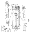
- the preferred location of DPA valve 160 is shown in FIG. 2 .
- DPA valve 160 may alternately be connected in other locations, as long as pump inlet 169 is located between inlet check valve 112 and outlet check valve 172 and retentate inlet 163 is located between the retentate side of RO element 186 and retentate chamber 136 .
- a more restrictive location of retentate inlet 163 is between the start of retentate return passage 146 and retentate chamber 136 . This more restrictive location allows retentate to be discharged without having the retentate reenter RO chamber 184 .
- DPA valve 160 operates as follows. On the compression stroke, pressures in pump chamber 126 and retentate chamber 136 are approximately equal. Pump chamber 126 pressure may be slightly higher than retentate chamber 136 pressure due to pressure losses in RO element 186 or elsewhere in the pump. Poppet 164 is in the “closed” position and blocks discharge line 171 from retentate chamber 136 . Poppet 164 is held firmly in place by applied forces due to the product of the applied pressures and the areas over which they are applied. The design of poppet 164 and chamber 162 are such that poppet 164 area exposed to pump chamber 126 pressure is larger than poppet 164 area exposed to retentate chamber 136 pressure. The differences in exposed poppet 164 areas results in a large force to firmly hold poppet 164 in place during the compression stroke.
- pressure in pump chamber 126 reduces to zero (gauge pressure) or slightly negative as water is sucked into chamber 126 .
- Movement of piston 128 during the intake stroke attempts to compress the liquid in retentate chamber 136 resulting in a high retentate chamber 136 pressure.
- the resulting pressure imbalance between retentate chamber 136 and pump chamber 126 moves poppet 164 to the “open” position and exposes discharge line 171 , allowing retentate chamber 136 liquid to pass through discharge line 171 . Excessive movement of poppet 164 is prevented by plug 170 .
- Poppet 164 and plug 170 preferably comprise injected molded plastic.
- poppet 164 seats and seals directly against a seat injection molded or machined into housing 100 .
- Seat end of poppet 164 is optionally covered with rubber or a similar material to assist in seating.
- Poppet 164 and/or plug 170 may optionally comprise cast or machined metal or machined plastic.
- chamber 162 is cast into housing 100 during the injection molding process. In alternate embodiments, chamber 162 is machined into housing 100 or a metal or other appropriate material tube is placed in the mold prior to injection molding.
- Pressure relief valve 150 is incorporated into housing 100 .
- Pressure relief valve 150 preferably comprises ball 154 , spring 156 , and plug 158 inside chamber 152 within housing 100 .
- Alternative embodiments comprise ball, disc, poppet, spring, or other sealing mechanisms.
- Pressure relief valve 150 opens and relieves pressure when pressure on ball 154 is sufficient to overcome the force in spring 156 which keeps ball 154 in the closed position.
- the purpose of pressure relief valve 150 is to limit the pressure in retentate chamber 136 that can be developed by the pump to a safe operating level.
- the preferred location of pressure relief valve 150 is shown in FIG. 2 . In alternate embodiments, pressure relief valve 150 may be located anywhere between outlet check valve 172 and retentate chamber 136 .
- chamber 152 is cast into housing 100 during the injection molding process. In alternate embodiments, chamber 152 is machined in housing 100 or a metal or other appropriate material tube is placed in the mold prior to injection molding.
- the second major element of this embodiment of the present invention is a reverse osmosis filter system.
- Reverse osmosis filters are very efficient filter systems removing very small particles including ions such as sodium and chloride.
- this system comprises a conventional spiral wound design RO filter element 186 .
- RO filter element 186 comprises ceramic membrane, carbon membrane monotubes, or other RO elements known to those versed in the design of RO elements. High TDS feed water at a pressure exceeding the osmotic pressure flows in to one end of cylindrical filter element 186 .
- the recovery ratio of RO element 186 is defined as the ratio of the volume of permeate (finished water) that is expelled to the feed water volume that is generated in one pump stroke in pump chamber 126 .
- the difference in volume between pump chamber 126 and retentate chamber 136 is uniquely defined by the volume of pump shaft 134 .
- the recovery ratio of RO filter element 186 is explicitly defined by the square of the ratio of pump shaft 134 diameter to retentate chamber 136 diameter.
- the feed water volume that enters RO element 186 generated in one pump stroke is the sum of permeate volume expelled plus retentate volume expelled.
- the permeate volume produced in one stroke of the pump is equivalent to the volume of the portion of pump shaft 134 that is within retentate chamber 136 , or is alternatively determined by the cross-sectional area of pump shaft 134 .
- the RO filter assembly as shown in FIG. 2 comprises a separate pressure chamber 184 with seals 192 , 196 and 204 to isolate the inlet feed stream, the retentate rejection stream and the permeate product stream.
- the RO filter element 186 can easily be changed by removing end cap 102 and RO end cap 194 and withdrawing RO element 186 from RO chamber 184 . Installation is the reverse procedure. Circular seal 204 on the outside of RO element 186 and inside cylinder housing 100 prevents retentate water from returning to the feed side of the RO filter element.
- pump jack mechanisms may be employed to force pump shaft 134 in and out of the pump housing 100 .
- force on piston shaft 134 is applied by manual force applied to a pump jack mechanism.
- a simple piston may be utilized.
- a piston shaft force generating mechanism comprising a reciprocating motion drive powered by petroleum based fuel drive engines, electric motors, or any other power generating device may be employed.
- lever arm 210 length for obtaining the mechanical advantage corresponds to the overall length of pump housing 100 .
- the end of lever arm 210 is optionally fitted with a large surface area pad 216 to reduce the point source load on the human anatomy.
- Pad 216 is preferably contoured to be conformal with pump housing 100 to facilitate compact storage.
- the length of lever arm 210 is optionally removably securable to pump housing 100 or end cap 102 for travel.
- housing eccentric 205 is an integral part of housing 100 .
- housing eccentric 205 comprises a separate part comprising injection molded plastic; cast or machined aluminum, steel, titanium; or other suitable material that is compatible with the pumping forces achieved, attached to housing 100 by conventional threaded fasteners or other means.
- lever arm 210 is a one piece injection molded part and is preferably attached to housing eccentric 205 by pin 206 with end clips 208 and to pump shaft 134 by pin 212 with end clips 214 .
- lever arm 210 comprises one or more pieces of injected molded plastic; cast or machined, solid, hollow, or filled aluminum, steel, or titanium; or other suitable material that is compatible with the pumping forces achieved.
- the pump jack mechanism incorporates an energy storage device to store up energy in the return stroke, as described above. The stored energy is then released on the pressure stroke to ease the force required to implement the pressure stroke. Under ideal conditions at a given TDS level, the stored energy is approximately half of the total force required to drive water through the RO membrane. Likewise, the peak force required of the operator to operate the pump in the power (pressure) stroke is reduced by half.
Abstract
Description
Claims (30)
Priority Applications (2)
| Application Number | Priority Date | Filing Date | Title |
|---|---|---|---|
| US10/759,750 US7244357B2 (en) | 1999-05-25 | 2004-01-16 | Pumps for filtration systems |
| PCT/US2004/003964 WO2005084178A2 (en) | 2003-02-11 | 2004-02-11 | Pumps for filtration systems |
Applications Claiming Priority (16)
| Application Number | Priority Date | Filing Date | Title |
|---|---|---|---|
| US31846999A | 1999-05-25 | 1999-05-25 | |
| US09/318,468 US6261464B1 (en) | 1999-05-25 | 1999-05-25 | Portable water disinfection system |
| US51443100A | 2000-02-28 | 2000-02-28 | |
| US09/579,178 US6524475B1 (en) | 1999-05-25 | 2000-05-24 | Portable water disinfection system |
| PCT/US2000/014513 WO2000071783A1 (en) | 1999-05-25 | 2000-05-25 | Portable disinfection and filtration system |
| US23089500P | 2000-09-05 | 2000-09-05 | |
| US09/686,214 US6558537B1 (en) | 1999-05-25 | 2000-10-10 | Portable hydration system |
| PCT/US2000/033254 WO2002020142A1 (en) | 2000-09-05 | 2000-12-08 | Reverse osmosis membrane and process for making same |
| US26665901P | 2001-02-05 | 2001-02-05 | |
| US30591201P | 2001-07-16 | 2001-07-16 | |
| US09/907,092 US6736966B2 (en) | 1999-05-25 | 2001-07-16 | Portable water disinfection system |
| PCT/US2002/022618 WO2003008076A1 (en) | 2001-07-16 | 2002-07-16 | Dual head pump driven membrane system |
| WOPCT/US02/22618 | 2002-07-16 | ||
| US44683003P | 2003-02-11 | 2003-02-11 | |
| US10/382,971 US7311831B2 (en) | 2000-09-05 | 2003-03-05 | Filtration membrane and method of making same |
| US10/759,750 US7244357B2 (en) | 1999-05-25 | 2004-01-16 | Pumps for filtration systems |
Related Parent Applications (3)
| Application Number | Title | Priority Date | Filing Date |
|---|---|---|---|
| US09/907,092 Continuation-In-Part US6736966B2 (en) | 1999-05-25 | 2001-07-16 | Portable water disinfection system |
| PCT/US2002/022618 Continuation-In-Part WO2003008076A1 (en) | 1999-05-25 | 2002-07-16 | Dual head pump driven membrane system |
| US10/382,971 Continuation-In-Part US7311831B2 (en) | 1999-05-25 | 2003-03-05 | Filtration membrane and method of making same |
Publications (2)
| Publication Number | Publication Date |
|---|---|
| US20040173528A1 US20040173528A1 (en) | 2004-09-09 |
| US7244357B2 true US7244357B2 (en) | 2007-07-17 |
Family
ID=34922585
Family Applications (1)
| Application Number | Title | Priority Date | Filing Date |
|---|---|---|---|
| US10/759,750 Expired - Fee Related US7244357B2 (en) | 1999-05-25 | 2004-01-16 | Pumps for filtration systems |
Country Status (2)
| Country | Link |
|---|---|
| US (1) | US7244357B2 (en) |
| WO (1) | WO2005084178A2 (en) |
Cited By (10)
| Publication number | Priority date | Publication date | Assignee | Title |
|---|---|---|---|---|
| US9540259B2 (en) | 2011-08-25 | 2017-01-10 | Electrolytic Ozone, Inc. | Apparatus for producing and delivering ozonated water |
| US10471391B2 (en) | 2016-11-19 | 2019-11-12 | Aqua Membranes, Inc. | Flow directing devices for spiral-wound elements |
| US10677238B2 (en) | 2017-11-08 | 2020-06-09 | Ingersoll-Rand Industrial U.S., Inc. | Filled resin layer separated pump housing |
| US11083997B2 (en) | 2017-04-20 | 2021-08-10 | Aqua Membranes Inc. | Non-nesting, non-deforming patterns for spiral-wound elements |
| US11090612B2 (en) | 2017-04-12 | 2021-08-17 | Aqua Membranes Inc. | Graded spacers for filtration wound elements |
| US11156219B2 (en) * | 2015-11-10 | 2021-10-26 | Repligen Corporation | Disposable alternating tangential flow filtration units |
| US11376552B2 (en) | 2016-09-20 | 2022-07-05 | Aqua Membranes Inc. | Permeate flow paterns |
| US11633700B2 (en) | 2020-04-07 | 2023-04-25 | Aqua Membranes Inc. | Independent spacers and methods |
| US11745143B2 (en) | 2017-04-20 | 2023-09-05 | Aqua Membranes, Inc. | Mixing-promoting spacer patterns for spiral-wound elements |
| US11745144B2 (en) | 2017-10-13 | 2023-09-05 | Aqua Membranes Inc. | Bridge support and reduced feed spacers for spiral-wound elements |
Families Citing this family (18)
| Publication number | Priority date | Publication date | Assignee | Title |
|---|---|---|---|---|
| WO2008121030A2 (en) | 2007-03-15 | 2008-10-09 | Obshchestvo S Ogranichennoj Otvetstvennost'yu 'tehnoprom' | Reverse osmosis freshwater plant (variants) |
| KR100963557B1 (en) * | 2008-06-11 | 2010-06-15 | 한국기계연구원 | Self reciprocated energy recovery device |
| FR2933969B1 (en) * | 2008-07-21 | 2011-11-11 | Degremont | INSTALLATION OF WATER DESALINATION BY REVERSE OSMOSIS |
| EP2216299A1 (en) * | 2009-02-06 | 2010-08-11 | EMW Europa Mobil Vattenrening AB | Method and device for purification of water |
| US20120298578A1 (en) * | 2010-02-01 | 2012-11-29 | Rodney Herrington | Systems and methods for filtration |
| EP2368624B1 (en) * | 2010-03-24 | 2016-08-10 | KSB Aktiengesellschaft | Assembly and method for treatment of a liquid by reverse osmosis |
| US9255512B2 (en) * | 2011-08-22 | 2016-02-09 | Cummins Emission Solutions, Inc. | Urea injection systems wash cycles |
| WO2013085755A2 (en) * | 2011-12-09 | 2013-06-13 | General Electric Company | Feed spacers for spiral wound membrane element |
| US20140326665A1 (en) * | 2013-05-03 | 2014-11-06 | Crestron Electronics, Inc. | Pressure Monitoring and Pump Speed Control for a Reverse Osmosis System |
| JPWO2015037645A1 (en) * | 2013-09-11 | 2017-03-02 | 株式会社荏原製作所 | Seawater desalination system |
| US10597308B2 (en) * | 2013-11-25 | 2020-03-24 | Kurita Water Industries Ltd. | Water treatment plant controlling method and controlling program, and water treatment system |
| WO2015131422A1 (en) * | 2014-03-05 | 2015-09-11 | 深圳澳特弗科技有限公司 | Intense pulsation micro wastewater discharge water purification system |
| CN105254103B (en) * | 2015-11-05 | 2017-09-19 | 广东工业大学 | A kind of classifying and reclaiming system and method for tin removal waste liquor |
| US11072065B2 (en) * | 2017-03-30 | 2021-07-27 | Wipro Limited | Robotic apparatus for building a multidimensional object |
| US11679339B2 (en) * | 2018-08-02 | 2023-06-20 | Plug Power Inc. | High-output atmospheric water generator |
| CN108869789A (en) * | 2018-08-20 | 2018-11-23 | 舟山青兰科技有限公司 | Two-position three way magnetic valve and device for corrosive liquids reverse osmosis treatment device |
| CN111379691A (en) * | 2018-12-28 | 2020-07-07 | 佛山市沃联电气有限公司 | Diaphragm pressure boost self-priming integrated pump adaptive to water source |
| CN110342612A (en) * | 2019-08-22 | 2019-10-18 | 广东叮咚净水科技有限公司 | The water shortage detection device of water purifier |
Citations (88)
| Publication number | Priority date | Publication date | Assignee | Title |
|---|---|---|---|---|
| US1029580A (en) | 1912-01-18 | 1912-06-18 | James O Bane | Counteracting device for pumps. |
| US1160528A (en) | 1915-01-25 | 1915-11-16 | William Renard Pilkington | Air or other fluid-pressure pump. |
| US1200165A (en) | 1913-10-30 | 1916-10-03 | Charles F Burgess | Method and apparatus for sterilizing. |
| US2473986A (en) | 1945-10-18 | 1949-06-21 | Wallace & Tiernan Co Inc | Water purification unit |
| US3222269A (en) | 1962-03-28 | 1965-12-07 | Robert E Stanton | Apparatus for producing hypochlorite solutions and introducing same into confined bodies of water |
| US3365061A (en) | 1965-10-04 | 1968-01-23 | Gulf General Atomic Inc | Portable reverse osmosis apparatus |
| US3505215A (en) | 1968-10-10 | 1970-04-07 | Desalination Systems | Method of treatment of liquids by reverse osmosis |
| US3558242A (en) | 1969-03-04 | 1971-01-26 | Petersen Candy International L | Pump for desalination plant |
| US3622479A (en) | 1969-06-04 | 1971-11-23 | Frank L Schneider | Method for the continuous electrolytic production of chlorine for the sterilization of water |
| US3654148A (en) | 1970-09-28 | 1972-04-04 | Puredesal Inc | Liquid purification system |
| US3749524A (en) | 1972-01-03 | 1973-07-31 | D Jordan | Manually operated pump utilizing backpressure for easement of pump stroke |
| US3791768A (en) | 1972-06-16 | 1974-02-12 | W Wanner | Fluid pump |
| US3825122A (en) | 1973-06-11 | 1974-07-23 | J Taylor | Reverse-osmosis pump |
| US4000065A (en) | 1974-11-18 | 1976-12-28 | Basf Wyandotte Corporation | Method and apparatus for purifying aqueous streams contaminated with organic materials |
| US4070280A (en) | 1976-11-17 | 1978-01-24 | Desalination Systems, Inc. | Manually operable reverse osmosis apparatus |
| US4077883A (en) | 1976-12-29 | 1978-03-07 | Desalination Systems, Inc. | Reverse osmosis system with automatic pressure relief valve |
| US4124488A (en) | 1976-02-27 | 1978-11-07 | Ocean Water Limited | Water purification by reverse osmosis |
| US4151092A (en) | 1977-07-11 | 1979-04-24 | Teledyne Industries, Inc. | Portable water filter |
| US4187173A (en) | 1977-03-28 | 1980-02-05 | Keefer Bowie | Reverse osmosis method and apparatus |
| US4219424A (en) | 1976-06-18 | 1980-08-26 | Industrial Research Institute | Apparatus for enriching oxygen contained in water |
| US4288326A (en) | 1978-03-14 | 1981-09-08 | Keefer Bowie | Rotary shaft driven reverse osmosis method and apparatus |
| US4290873A (en) | 1979-06-25 | 1981-09-22 | Weaver Ron L | Chlorine gas generator apparatus |
| US4306952A (en) | 1979-05-25 | 1981-12-22 | Magneto-Chemie B.V. | Electrolytic process and apparatus |
| US4321137A (en) | 1979-02-26 | 1982-03-23 | Maschinenfabrik Buckau R. Wolf Ag | Apparatus for processing liquids such as water and the like by reverse osmosis |
| US4367140A (en) | 1979-11-05 | 1983-01-04 | Sykes Ocean Water Ltd. | Reverse osmosis liquid purification apparatus |
| US4389311A (en) | 1980-05-05 | 1983-06-21 | Freniere Henry | Portable water purifier |
| US4432876A (en) | 1980-07-30 | 1984-02-21 | Seagold Industries Corporation | Reverse osmosis apparatus and method incorporating external fluid exchange |
| US4434056A (en) | 1979-04-06 | 1984-02-28 | Keefer Bowie | Multi-cylinder reverse osmosis apparatus and method |
| US4496443A (en) | 1982-06-08 | 1985-01-29 | Mack Michael H | Method for electrically introducing substances into liquid solution |
| US4534713A (en) | 1984-08-10 | 1985-08-13 | Wanner William F | Pump apparatus |
| US4560455A (en) | 1983-02-03 | 1985-12-24 | Battelle Memorial Institute | Apparatus for sterilizing objects with an aqueous hypochlorite solution |
| USRE32144E (en) | 1977-03-28 | 1986-05-13 | Reverse osmosis method and apparatus | |
| US4632754A (en) | 1982-10-12 | 1986-12-30 | Plessey Overseas Limited | Desalination apparatus |
| US4722263A (en) | 1986-04-11 | 1988-02-02 | Ingo Valentin | Portable hydraulic pump |
| US4724079A (en) | 1985-01-11 | 1988-02-09 | Gloria Stephan Sale | Water purification process |
| US4744877A (en) | 1987-05-14 | 1988-05-17 | Maddock Robert E | Apparatus for generating chlorine gas |
| US4756830A (en) | 1987-05-18 | 1988-07-12 | Edward Fredkin | Pumping apparatus |
| US4759844A (en) | 1986-03-21 | 1988-07-26 | Aquathin Corp. | Portable water purification system |
| US4761208A (en) | 1986-09-29 | 1988-08-02 | Los Alamos Technical Associates, Inc. | Electrolytic method and cell for sterilizing water |
| US4765807A (en) | 1986-02-11 | 1988-08-23 | Norsk Hydro A.S. | Method and apparatus for the oxygen enrichment of water |
| US4786380A (en) | 1985-04-15 | 1988-11-22 | Nederlandse Centrale Organisatie Voor Toegepast-Natuurewetenschappelij Onderzoek | Method for the electrolytic preparation of hypochlorite in flowing salt-containing water |
| US4790946A (en) | 1985-08-27 | 1988-12-13 | Jansen Hermanus J | Process for the preparation of a disinfectant for water, such as drinking- or swimming-water |
| US4790923A (en) | 1987-07-07 | 1988-12-13 | Stillman Neil W | Liquid treating electrolytic cell |
| US4836924A (en) | 1987-10-21 | 1989-06-06 | Solomon Donald F | Reverse osmosis system and automatic cycling booster pump therefor |
| US4861487A (en) | 1989-02-08 | 1989-08-29 | Fulk Jr Clyde W | Spiral wound membrane modules and systems with improved feed spacer |
| USRE33135E (en) | 1984-08-10 | 1989-12-26 | Recovery Engineering | Pump apparatus |
| US4929347A (en) * | 1988-07-11 | 1990-05-29 | Sasakura Engineering Co., Ltd. | Concentrating apparatus with reverse osmosis membrane |
| US4973408A (en) | 1987-04-13 | 1990-11-27 | Keefer Bowie | Reverse osmosis with free rotor booster pump |
| US4976842A (en) | 1989-05-01 | 1990-12-11 | Envirodynamics Limited | Oxidant generator |
| US5006352A (en) | 1987-02-27 | 1991-04-09 | Mester-Coop Elelmiszeripari Es Ker. Leanyvallalat | Process for the production of an oxygenated restorative drink |
| US5085753A (en) | 1989-02-21 | 1992-02-04 | Floatron, Inc. | Water purifier |
| US5207916A (en) | 1992-05-20 | 1993-05-04 | Mesco, Inc. | Reverse osmosis system |
| US5244579A (en) | 1992-10-09 | 1993-09-14 | Zenon Environmental Inc. | Transportable reverse osmosis water purification unit |
| US5295519A (en) | 1988-10-14 | 1994-03-22 | Elkay Manufacturing Company | Hygienic liquid dispensing system including feed tube or probe for opening and resealing coaxial cap |
| US5306428A (en) | 1992-10-29 | 1994-04-26 | Tonner John B | Method of recovering energy from reverse osmosis waste streams |
| US5320718A (en) | 1990-08-07 | 1994-06-14 | United Technologies Corporation | Method for removing oxidizable organic compounds from an aqueous solution |
| US5324666A (en) | 1988-08-13 | 1994-06-28 | Siepmann Friedrich W | Process for determining oxidizable substances contained in an aqueous sample liquid |
| US5358635A (en) | 1993-04-16 | 1994-10-25 | Ecowater Systems, Inc. | Integrated reverse osmosis water treatment and storage system |
| WO1995029130A1 (en) | 1994-04-27 | 1995-11-02 | Life International | Oxygen enriched liquids, method and apparatus for making, and applications thereof |
| US5480386A (en) | 1992-09-16 | 1996-01-02 | Debiotech Sa | Pump assembly for medical use |
| US5492534A (en) | 1990-04-02 | 1996-02-20 | Pharmetrix Corporation | Controlled release portable pump |
| US5496466A (en) | 1993-09-14 | 1996-03-05 | Teledyne Industries, Inc. | Portable water purification system with double piston pump |
| US5503736A (en) | 1994-04-28 | 1996-04-02 | Aquatec Water Systems, Inc. | Hydroboost piston pump for reverse osmosis system |
| US5531887A (en) | 1995-05-24 | 1996-07-02 | Howell Laboratories, Inc. | Manually operated reverse osmosis desalinization system |
| US5534145A (en) | 1991-04-09 | 1996-07-09 | Sweetwater, Inc. | Compact water filtration pump |
| US5540848A (en) | 1994-12-13 | 1996-07-30 | Vortex Corporation | Filter retainer for water purification unit |
| US5540355A (en) | 1990-10-24 | 1996-07-30 | Water Chef | Water cooler and dispensing system |
| US5558762A (en) | 1991-07-19 | 1996-09-24 | Msr | Portable water filter and valve assembly |
| US5581189A (en) | 1992-03-17 | 1996-12-03 | Brenn; Eric W. | Water purity testing system having reversing polarity |
| US5597482A (en) | 1995-04-25 | 1997-01-28 | Melyon; Solly | Water purification apparatus |
| US5647416A (en) | 1996-03-15 | 1997-07-15 | Les Produits Addico Inc. | Bottled water dispenser system |
| US5685980A (en) | 1996-03-07 | 1997-11-11 | Patapoff; Walter | Miniaturized handheld desalination field unit |
| US5699669A (en) | 1996-07-15 | 1997-12-23 | Gebhard; Albert W. | Air-circulating base for bottled water cooling and dispensing apparatus |
| US5725758A (en) | 1996-08-22 | 1998-03-10 | Water Refining Inc. | Filtration system and assembly |
| US5795459A (en) | 1996-07-29 | 1998-08-18 | Sweeney; Charles T. | Apparatus and method for water purification |
| US5900212A (en) | 1997-01-27 | 1999-05-04 | Hydro-Photon, Inc. | Hand-held ultraviolet water purification system |
| US5911870A (en) | 1997-04-11 | 1999-06-15 | H20 Technologies, Ltd. | Housing and method that provide extended resident time for dissolving generated oxygen into water |
| US5958229A (en) | 1997-04-02 | 1999-09-28 | The United States Of America As Represented By The Secretary Of The Navy | Electrolytic disinfectant system |
| US5989396A (en) | 1997-04-02 | 1999-11-23 | Eltech Systems Corporation | Electrode and electrolytic cell containing same |
| US6007686A (en) | 1994-08-26 | 1999-12-28 | Medical Discoveries, Inc. | System for elctrolyzing fluids for use as antimicrobial agents |
| US6017447A (en) | 1997-06-19 | 2000-01-25 | Oxygen8, Inc. | Oxygenated water cooler |
| US6180014B1 (en) | 1999-12-10 | 2001-01-30 | Amir Salama | Device and method for treating water with ozone generated by water electrolysis |
| US6203696B1 (en) | 1996-11-21 | 2001-03-20 | Colin Pearson | Fluid driven pumps and apparatus employing such pumps |
| US6524475B1 (en) | 1999-05-25 | 2003-02-25 | Miox Corporation | Portable water disinfection system |
| US6558537B1 (en) | 1999-05-25 | 2003-05-06 | Miox Corporation | Portable hydration system |
| US6609070B1 (en) | 1998-06-19 | 2003-08-19 | Rodi Systems Corp | Fluid treatment apparatus |
| US6736966B2 (en) | 1999-05-25 | 2004-05-18 | Miox Corporation | Portable water disinfection system |
| US6841076B1 (en) | 1999-07-20 | 2005-01-11 | Aloys Wobben | Method and device for desalting water |
Family Cites Families (1)
| Publication number | Priority date | Publication date | Assignee | Title |
|---|---|---|---|---|
| US434056A (en) * | 1890-08-12 | Railroad-scales |
-
2004
- 2004-01-16 US US10/759,750 patent/US7244357B2/en not_active Expired - Fee Related
- 2004-02-11 WO PCT/US2004/003964 patent/WO2005084178A2/en active Application Filing
Patent Citations (91)
| Publication number | Priority date | Publication date | Assignee | Title |
|---|---|---|---|---|
| US1029580A (en) | 1912-01-18 | 1912-06-18 | James O Bane | Counteracting device for pumps. |
| US1200165A (en) | 1913-10-30 | 1916-10-03 | Charles F Burgess | Method and apparatus for sterilizing. |
| US1160528A (en) | 1915-01-25 | 1915-11-16 | William Renard Pilkington | Air or other fluid-pressure pump. |
| US2473986A (en) | 1945-10-18 | 1949-06-21 | Wallace & Tiernan Co Inc | Water purification unit |
| US3222269A (en) | 1962-03-28 | 1965-12-07 | Robert E Stanton | Apparatus for producing hypochlorite solutions and introducing same into confined bodies of water |
| US3365061A (en) | 1965-10-04 | 1968-01-23 | Gulf General Atomic Inc | Portable reverse osmosis apparatus |
| US3505215A (en) | 1968-10-10 | 1970-04-07 | Desalination Systems | Method of treatment of liquids by reverse osmosis |
| US3558242A (en) | 1969-03-04 | 1971-01-26 | Petersen Candy International L | Pump for desalination plant |
| US3622479A (en) | 1969-06-04 | 1971-11-23 | Frank L Schneider | Method for the continuous electrolytic production of chlorine for the sterilization of water |
| US3654148A (en) | 1970-09-28 | 1972-04-04 | Puredesal Inc | Liquid purification system |
| US3749524A (en) | 1972-01-03 | 1973-07-31 | D Jordan | Manually operated pump utilizing backpressure for easement of pump stroke |
| US3791768A (en) | 1972-06-16 | 1974-02-12 | W Wanner | Fluid pump |
| US3825122A (en) | 1973-06-11 | 1974-07-23 | J Taylor | Reverse-osmosis pump |
| US4000065A (en) | 1974-11-18 | 1976-12-28 | Basf Wyandotte Corporation | Method and apparatus for purifying aqueous streams contaminated with organic materials |
| US4124488A (en) | 1976-02-27 | 1978-11-07 | Ocean Water Limited | Water purification by reverse osmosis |
| US4219424A (en) | 1976-06-18 | 1980-08-26 | Industrial Research Institute | Apparatus for enriching oxygen contained in water |
| US4070280A (en) | 1976-11-17 | 1978-01-24 | Desalination Systems, Inc. | Manually operable reverse osmosis apparatus |
| US4077883A (en) | 1976-12-29 | 1978-03-07 | Desalination Systems, Inc. | Reverse osmosis system with automatic pressure relief valve |
| US4187173A (en) | 1977-03-28 | 1980-02-05 | Keefer Bowie | Reverse osmosis method and apparatus |
| USRE32144E (en) | 1977-03-28 | 1986-05-13 | Reverse osmosis method and apparatus | |
| US4151092A (en) | 1977-07-11 | 1979-04-24 | Teledyne Industries, Inc. | Portable water filter |
| US4288326A (en) | 1978-03-14 | 1981-09-08 | Keefer Bowie | Rotary shaft driven reverse osmosis method and apparatus |
| US4321137A (en) | 1979-02-26 | 1982-03-23 | Maschinenfabrik Buckau R. Wolf Ag | Apparatus for processing liquids such as water and the like by reverse osmosis |
| US4434056A (en) | 1979-04-06 | 1984-02-28 | Keefer Bowie | Multi-cylinder reverse osmosis apparatus and method |
| US4306952A (en) | 1979-05-25 | 1981-12-22 | Magneto-Chemie B.V. | Electrolytic process and apparatus |
| US4290873A (en) | 1979-06-25 | 1981-09-22 | Weaver Ron L | Chlorine gas generator apparatus |
| US4367140A (en) | 1979-11-05 | 1983-01-04 | Sykes Ocean Water Ltd. | Reverse osmosis liquid purification apparatus |
| US4389311A (en) | 1980-05-05 | 1983-06-21 | Freniere Henry | Portable water purifier |
| US4432876A (en) | 1980-07-30 | 1984-02-21 | Seagold Industries Corporation | Reverse osmosis apparatus and method incorporating external fluid exchange |
| US4496443A (en) | 1982-06-08 | 1985-01-29 | Mack Michael H | Method for electrically introducing substances into liquid solution |
| US4632754A (en) | 1982-10-12 | 1986-12-30 | Plessey Overseas Limited | Desalination apparatus |
| US4560455A (en) | 1983-02-03 | 1985-12-24 | Battelle Memorial Institute | Apparatus for sterilizing objects with an aqueous hypochlorite solution |
| US4534713A (en) | 1984-08-10 | 1985-08-13 | Wanner William F | Pump apparatus |
| USRE33135E (en) | 1984-08-10 | 1989-12-26 | Recovery Engineering | Pump apparatus |
| US4724079A (en) | 1985-01-11 | 1988-02-09 | Gloria Stephan Sale | Water purification process |
| US4786380A (en) | 1985-04-15 | 1988-11-22 | Nederlandse Centrale Organisatie Voor Toegepast-Natuurewetenschappelij Onderzoek | Method for the electrolytic preparation of hypochlorite in flowing salt-containing water |
| US4790946A (en) | 1985-08-27 | 1988-12-13 | Jansen Hermanus J | Process for the preparation of a disinfectant for water, such as drinking- or swimming-water |
| US4765807A (en) | 1986-02-11 | 1988-08-23 | Norsk Hydro A.S. | Method and apparatus for the oxygen enrichment of water |
| US4759844A (en) | 1986-03-21 | 1988-07-26 | Aquathin Corp. | Portable water purification system |
| US4722263A (en) | 1986-04-11 | 1988-02-02 | Ingo Valentin | Portable hydraulic pump |
| US4761208A (en) | 1986-09-29 | 1988-08-02 | Los Alamos Technical Associates, Inc. | Electrolytic method and cell for sterilizing water |
| US5006352A (en) | 1987-02-27 | 1991-04-09 | Mester-Coop Elelmiszeripari Es Ker. Leanyvallalat | Process for the production of an oxygenated restorative drink |
| US4973408A (en) | 1987-04-13 | 1990-11-27 | Keefer Bowie | Reverse osmosis with free rotor booster pump |
| US4744877A (en) | 1987-05-14 | 1988-05-17 | Maddock Robert E | Apparatus for generating chlorine gas |
| US4756830A (en) | 1987-05-18 | 1988-07-12 | Edward Fredkin | Pumping apparatus |
| US4790923A (en) | 1987-07-07 | 1988-12-13 | Stillman Neil W | Liquid treating electrolytic cell |
| US4836924A (en) | 1987-10-21 | 1989-06-06 | Solomon Donald F | Reverse osmosis system and automatic cycling booster pump therefor |
| US4929347A (en) * | 1988-07-11 | 1990-05-29 | Sasakura Engineering Co., Ltd. | Concentrating apparatus with reverse osmosis membrane |
| US5324666A (en) | 1988-08-13 | 1994-06-28 | Siepmann Friedrich W | Process for determining oxidizable substances contained in an aqueous sample liquid |
| US5295519A (en) | 1988-10-14 | 1994-03-22 | Elkay Manufacturing Company | Hygienic liquid dispensing system including feed tube or probe for opening and resealing coaxial cap |
| US4861487A (en) | 1989-02-08 | 1989-08-29 | Fulk Jr Clyde W | Spiral wound membrane modules and systems with improved feed spacer |
| US5085753A (en) | 1989-02-21 | 1992-02-04 | Floatron, Inc. | Water purifier |
| US4976842A (en) | 1989-05-01 | 1990-12-11 | Envirodynamics Limited | Oxidant generator |
| US5492534A (en) | 1990-04-02 | 1996-02-20 | Pharmetrix Corporation | Controlled release portable pump |
| US5320718A (en) | 1990-08-07 | 1994-06-14 | United Technologies Corporation | Method for removing oxidizable organic compounds from an aqueous solution |
| US5540355A (en) | 1990-10-24 | 1996-07-30 | Water Chef | Water cooler and dispensing system |
| US5534145A (en) | 1991-04-09 | 1996-07-09 | Sweetwater, Inc. | Compact water filtration pump |
| US5558762A (en) | 1991-07-19 | 1996-09-24 | Msr | Portable water filter and valve assembly |
| US5581189A (en) | 1992-03-17 | 1996-12-03 | Brenn; Eric W. | Water purity testing system having reversing polarity |
| US5207916A (en) | 1992-05-20 | 1993-05-04 | Mesco, Inc. | Reverse osmosis system |
| US5480386A (en) | 1992-09-16 | 1996-01-02 | Debiotech Sa | Pump assembly for medical use |
| US5244579A (en) | 1992-10-09 | 1993-09-14 | Zenon Environmental Inc. | Transportable reverse osmosis water purification unit |
| US5306428A (en) | 1992-10-29 | 1994-04-26 | Tonner John B | Method of recovering energy from reverse osmosis waste streams |
| US5358635A (en) | 1993-04-16 | 1994-10-25 | Ecowater Systems, Inc. | Integrated reverse osmosis water treatment and storage system |
| US5496466A (en) | 1993-09-14 | 1996-03-05 | Teledyne Industries, Inc. | Portable water purification system with double piston pump |
| WO1995029130A1 (en) | 1994-04-27 | 1995-11-02 | Life International | Oxygen enriched liquids, method and apparatus for making, and applications thereof |
| US5503736A (en) | 1994-04-28 | 1996-04-02 | Aquatec Water Systems, Inc. | Hydroboost piston pump for reverse osmosis system |
| US6007686A (en) | 1994-08-26 | 1999-12-28 | Medical Discoveries, Inc. | System for elctrolyzing fluids for use as antimicrobial agents |
| US5540848A (en) | 1994-12-13 | 1996-07-30 | Vortex Corporation | Filter retainer for water purification unit |
| US5597482A (en) | 1995-04-25 | 1997-01-28 | Melyon; Solly | Water purification apparatus |
| US5531887A (en) | 1995-05-24 | 1996-07-02 | Howell Laboratories, Inc. | Manually operated reverse osmosis desalinization system |
| US5685980A (en) | 1996-03-07 | 1997-11-11 | Patapoff; Walter | Miniaturized handheld desalination field unit |
| US5647416A (en) | 1996-03-15 | 1997-07-15 | Les Produits Addico Inc. | Bottled water dispenser system |
| US5699669A (en) | 1996-07-15 | 1997-12-23 | Gebhard; Albert W. | Air-circulating base for bottled water cooling and dispensing apparatus |
| US5795459A (en) | 1996-07-29 | 1998-08-18 | Sweeney; Charles T. | Apparatus and method for water purification |
| US5928490A (en) | 1996-07-29 | 1999-07-27 | Sweeney; Charles T. | Laundry wash process and waste water treatment system |
| US5725758A (en) | 1996-08-22 | 1998-03-10 | Water Refining Inc. | Filtration system and assembly |
| US6203696B1 (en) | 1996-11-21 | 2001-03-20 | Colin Pearson | Fluid driven pumps and apparatus employing such pumps |
| US5900212A (en) | 1997-01-27 | 1999-05-04 | Hydro-Photon, Inc. | Hand-held ultraviolet water purification system |
| US6110424A (en) | 1997-01-27 | 2000-08-29 | Hydro-Photon, Inc. | Hand-held ultraviolet water purification system |
| US5958229A (en) | 1997-04-02 | 1999-09-28 | The United States Of America As Represented By The Secretary Of The Navy | Electrolytic disinfectant system |
| US5989396A (en) | 1997-04-02 | 1999-11-23 | Eltech Systems Corporation | Electrode and electrolytic cell containing same |
| US5911870A (en) | 1997-04-11 | 1999-06-15 | H20 Technologies, Ltd. | Housing and method that provide extended resident time for dissolving generated oxygen into water |
| US6017447A (en) | 1997-06-19 | 2000-01-25 | Oxygen8, Inc. | Oxygenated water cooler |
| US6197189B1 (en) | 1997-06-19 | 2001-03-06 | Oxygen8, Inc. | Oxygenated water cooler |
| US6609070B1 (en) | 1998-06-19 | 2003-08-19 | Rodi Systems Corp | Fluid treatment apparatus |
| US6524475B1 (en) | 1999-05-25 | 2003-02-25 | Miox Corporation | Portable water disinfection system |
| US6558537B1 (en) | 1999-05-25 | 2003-05-06 | Miox Corporation | Portable hydration system |
| US6736966B2 (en) | 1999-05-25 | 2004-05-18 | Miox Corporation | Portable water disinfection system |
| US6841076B1 (en) | 1999-07-20 | 2005-01-11 | Aloys Wobben | Method and device for desalting water |
| US6180014B1 (en) | 1999-12-10 | 2001-01-30 | Amir Salama | Device and method for treating water with ozone generated by water electrolysis |
Non-Patent Citations (3)
| Title |
|---|
| "Steri-Pen", Internet advertisement by Hydro-Photon, www.hydro-photon.com, (May 9, 2000). |
| Gupta, B.B. , et al., "Permeate flux enhancement by pressure and flow pulsations in microfiltration with mineral membranes", Journal of Membrane Science 70, 70,(1992),257-266. |
| Venczel, L.V. , "Inactivation of Cryptosporidium parvum Oocysts and Clostridium perfringens Spores by a Mixed-Oxidant Disinfectant and by Free Chlorine", Applied and Environmental Microbiology, vol. 63, No. 4, (Apr. 1997),1598-1601. |
Cited By (14)
| Publication number | Priority date | Publication date | Assignee | Title |
|---|---|---|---|---|
| US9540259B2 (en) | 2011-08-25 | 2017-01-10 | Electrolytic Ozone, Inc. | Apparatus for producing and delivering ozonated water |
| US11156219B2 (en) * | 2015-11-10 | 2021-10-26 | Repligen Corporation | Disposable alternating tangential flow filtration units |
| US20220008803A1 (en) * | 2015-11-10 | 2022-01-13 | Repligen Corporation | Disposable Alternating Tangential Flow Filtration Units |
| US11376552B2 (en) | 2016-09-20 | 2022-07-05 | Aqua Membranes Inc. | Permeate flow paterns |
| US11040311B2 (en) | 2016-11-19 | 2021-06-22 | Aqua Membranes Inc. | Interference patterns for spiral wound elements |
| US10471391B2 (en) | 2016-11-19 | 2019-11-12 | Aqua Membranes, Inc. | Flow directing devices for spiral-wound elements |
| US11090612B2 (en) | 2017-04-12 | 2021-08-17 | Aqua Membranes Inc. | Graded spacers for filtration wound elements |
| US11612862B2 (en) | 2017-04-12 | 2023-03-28 | Aqua Membranes Inc. | Graded spacers in spiral wound elements |
| US11083997B2 (en) | 2017-04-20 | 2021-08-10 | Aqua Membranes Inc. | Non-nesting, non-deforming patterns for spiral-wound elements |
| US11745143B2 (en) | 2017-04-20 | 2023-09-05 | Aqua Membranes, Inc. | Mixing-promoting spacer patterns for spiral-wound elements |
| US11896933B2 (en) | 2017-04-20 | 2024-02-13 | Aqua Membranes Inc. | Non-nesting, non-deforming patterns for spiral-wound elements |
| US11745144B2 (en) | 2017-10-13 | 2023-09-05 | Aqua Membranes Inc. | Bridge support and reduced feed spacers for spiral-wound elements |
| US10677238B2 (en) | 2017-11-08 | 2020-06-09 | Ingersoll-Rand Industrial U.S., Inc. | Filled resin layer separated pump housing |
| US11633700B2 (en) | 2020-04-07 | 2023-04-25 | Aqua Membranes Inc. | Independent spacers and methods |
Also Published As
| Publication number | Publication date |
|---|---|
| WO2005084178A3 (en) | 2006-01-05 |
| US20040173528A1 (en) | 2004-09-09 |
| WO2005084178A2 (en) | 2005-09-15 |
Similar Documents
| Publication | Publication Date | Title |
|---|---|---|
| US7244357B2 (en) | Pumps for filtration systems | |
| US7297268B2 (en) | Dual head pump driven filtration system | |
| EP1453592B1 (en) | Dual head pump driven membrane system | |
| Fersi et al. | Treatment of textile plant effluent by ultrafiltration and/or nanofiltration for water reuse | |
| EP1963673B1 (en) | Highly efficient durable fluid pump and method | |
| AU718975B2 (en) | Fluid driven pumps and apparatus employing such pumps | |
| US5589066A (en) | Portable water purification system | |
| US9969624B2 (en) | Personal water filter device | |
| US8292088B2 (en) | Water supply system with filtration and retrofit assembly | |
| US20040164022A1 (en) | Reverse osmosis system | |
| KR20110100471A (en) | Apparatus for recovering energy for desalinization system of sea-water | |
| CN106865695B (en) | Dense water hydraulic RO water storage system | |
| CN202016907U (en) | Multipurpose engine driven fool style seawater desalination device | |
| CN201161943Y (en) | Double-cylinder energy conservation sea water desalting apparatus | |
| CN219991246U (en) | Energy-saving water-saving multi-mode control nanofiltration water purifier | |
| CN212799891U (en) | Supercharging device and seawater desalination equipment | |
| CN212799890U (en) | Seawater desalination equipment | |
| JPH0417219Y2 (en) | ||
| CN212559697U (en) | Circulating instant-filtering type super-clean-flow reverse osmosis direct drinking machine | |
| CN211770604U (en) | Shipborne seawater desalination device | |
| CN210261238U (en) | Energy recovery device for high-pressure reverse osmosis | |
| CN217350848U (en) | Control system capable of effectively reducing 'stale water' TDS value in reverse osmosis membrane | |
| CN215886571U (en) | Reverse osmosis is back flush unit and water purifier of leading filter core for water purifier | |
| CN214060095U (en) | Water purifier | |
| CN217340314U (en) | Quantitative water outlet system and water purifier |
Legal Events
| Date | Code | Title | Description |
|---|---|---|---|
| AS | Assignment |
Owner name: MIOX CORPORATION, NEW MEXICO Free format text: ASSIGNMENT OF ASSIGNORS INTEREST;ASSIGNORS:HERRINGTON, RODNEY E.;HAND, FRANK;REEL/FRAME:015344/0245 Effective date: 20040216 |
|
| AS | Assignment |
Owner name: SILICON VALLEY BANK, CALIFORNIA Free format text: SECURITY AGREEMENT;ASSIGNOR:MIOX CORPORATION;REEL/FRAME:017094/0299 Effective date: 20050923 |
|
| AS | Assignment |
Owner name: MIOX CORPORATION, NEW MEXICO Free format text: RELEASE;ASSIGNOR:SILICON VALLEY BANK;REEL/FRAME:019549/0261 Effective date: 20070702 |
|
| AS | Assignment |
Owner name: TRIPLEPOINT CAPITAL LLC, CALIFORNIA Free format text: SECURITY AGREEMENT;ASSIGNOR:MIOX CORPORATION;REEL/FRAME:019567/0533 Effective date: 20070629 Owner name: TRIPLEPOINT CAPITAL LLC,CALIFORNIA Free format text: SECURITY AGREEMENT;ASSIGNOR:MIOX CORPORATION;REEL/FRAME:019567/0533 Effective date: 20070629 |
|
| AS | Assignment |
Owner name: MIOX CORPORATION (AKA MIOX, INC.), NEW MEXICO Free format text: RELEASE BY SECURED PARTY;ASSIGNOR:TRIPLEPOINT CAPITAL LLC;REEL/FRAME:025105/0714 Effective date: 20101005 |
|
| REMI | Maintenance fee reminder mailed | ||
| FPAY | Fee payment |
Year of fee payment: 4 |
|
| SULP | Surcharge for late payment | ||
| AS | Assignment |
Owner name: UNION BAY CAPTIAL PARTNERS I, LLC, WASHINGTON Free format text: SECURITY INTEREST;ASSIGNOR:MIOX CORPORATION;REEL/FRAME:034609/0287 Effective date: 20141230 |
|
| REMI | Maintenance fee reminder mailed | ||
| LAPS | Lapse for failure to pay maintenance fees | ||
| REIN | Reinstatement after maintenance fee payment confirmed | ||
| FP | Lapsed due to failure to pay maintenance fee |
Effective date: 20150717 |
|
| FEPP | Fee payment procedure |
Free format text: PETITION RELATED TO MAINTENANCE FEES GRANTED (ORIGINAL EVENT CODE: PMFG); ENTITY STATUS OF PATENT OWNER: SMALL ENTITY Free format text: PETITION RELATED TO MAINTENANCE FEES FILED (ORIGINAL EVENT CODE: PMFP); ENTITY STATUS OF PATENT OWNER: SMALL ENTITY |
|
| AS | Assignment |
Owner name: MIOX CORPORATION, NEW MEXICO Free format text: RELEASE BY SECURED PARTY;ASSIGNOR:UNION BAY CAPTIAL PARTNERS I, LLC;REEL/FRAME:038176/0968 Effective date: 20160331 |
|
| AS | Assignment |
Owner name: AQUA RESEARCH LLC, NEW MEXICO Free format text: ASSIGNMENT OF ASSIGNORS INTEREST;ASSIGNOR:MIOX CORPORATION;REEL/FRAME:038778/0799 Effective date: 20160526 |
|
| PRDP | Patent reinstated due to the acceptance of a late maintenance fee |
Effective date: 20160713 |
|
| FPAY | Fee payment |
Year of fee payment: 8 |
|
| STCF | Information on status: patent grant |
Free format text: PATENTED CASE |
|
| SULP | Surcharge for late payment | ||
| FEPP | Fee payment procedure |
Free format text: MAINTENANCE FEE REMINDER MAILED (ORIGINAL EVENT CODE: REM.); ENTITY STATUS OF PATENT OWNER: SMALL ENTITY |
|
| LAPS | Lapse for failure to pay maintenance fees |
Free format text: PATENT EXPIRED FOR FAILURE TO PAY MAINTENANCE FEES (ORIGINAL EVENT CODE: EXP.); ENTITY STATUS OF PATENT OWNER: SMALL ENTITY |
|
| STCH | Information on status: patent discontinuation |
Free format text: PATENT EXPIRED DUE TO NONPAYMENT OF MAINTENANCE FEES UNDER 37 CFR 1.362 |
|
| FP | Lapsed due to failure to pay maintenance fee |
Effective date: 20190717 |