US7217237B2 - Closing system and electronic control method - Google Patents
Closing system and electronic control method Download PDFInfo
- Publication number
- US7217237B2 US7217237B2 US10/496,423 US49642305A US7217237B2 US 7217237 B2 US7217237 B2 US 7217237B2 US 49642305 A US49642305 A US 49642305A US 7217237 B2 US7217237 B2 US 7217237B2
- Authority
- US
- United States
- Prior art keywords
- signal
- pressure
- output signal
- monostable
- function
- Prior art date
- Legal status (The legal status is an assumption and is not a legal conclusion. Google has not performed a legal analysis and makes no representation as to the accuracy of the status listed.)
- Expired - Fee Related
Links
Images


Classifications
-
- A—HUMAN NECESSITIES
- A61—MEDICAL OR VETERINARY SCIENCE; HYGIENE
- A61F—FILTERS IMPLANTABLE INTO BLOOD VESSELS; PROSTHESES; DEVICES PROVIDING PATENCY TO, OR PREVENTING COLLAPSING OF, TUBULAR STRUCTURES OF THE BODY, e.g. STENTS; ORTHOPAEDIC, NURSING OR CONTRACEPTIVE DEVICES; FOMENTATION; TREATMENT OR PROTECTION OF EYES OR EARS; BANDAGES, DRESSINGS OR ABSORBENT PADS; FIRST-AID KITS
- A61F2/00—Filters implantable into blood vessels; Prostheses, i.e. artificial substitutes or replacements for parts of the body; Appliances for connecting them with the body; Devices providing patency to, or preventing collapsing of, tubular structures of the body, e.g. stents
- A61F2/0004—Closure means for urethra or rectum, i.e. anti-incontinence devices or support slings against pelvic prolapse
- A61F2/0031—Closure means for urethra or rectum, i.e. anti-incontinence devices or support slings against pelvic prolapse for constricting the lumen; Support slings for the urethra
- A61F2/0036—Closure means for urethra or rectum, i.e. anti-incontinence devices or support slings against pelvic prolapse for constricting the lumen; Support slings for the urethra implantable
- A61F2/004—Closure means for urethra or rectum, i.e. anti-incontinence devices or support slings against pelvic prolapse for constricting the lumen; Support slings for the urethra implantable inflatable
Definitions
- the following invention relates to a closing system and a correspondingly suitable method for the selective opening and closing of a tubular body organ.
- an implantable device for the selective opening and closing of tubular body organs is known, with an elongated valve body being provided which is insertable into the tubular body organ.
- the valve body has a shutoff device which can be selectively closed and released.
- the valve body has an elastic hose section in which an inflatable body is arranged which is inflatable by a fluid and then closes the lumen of the hose section. Opening as well as closing is done by manual handling, i.e. inflation of the inflatable body is done by manual operation of a pump and opening is by manual operation of a switch.
- one objective of the present invention is to further develop the known closing system or, respectively, the known method for the selective opening and closing of a tubular body organ such that any pressure increases in the body organ to be closed will be counteracted short-term and the risk of necrosis will be nearly excluded.
- Another objective of the present invention is to provide a closing system which ensures continence at any time.
- the closing system or, respectively, the method according to the invention for the selective opening and closing of a tubular body organ provides a closing element and a regulating system controlling the closing element, with the regulating system setting a first condition of the closing system and returning, in a self-regulating manner, a deviation from the first condition back to the first condition.
- This measure in accordance with the application will achieve that—with pressure peaks or, respectively, pressure loads occurring due to coughing, sneezing, laughing or bending over—the required objectives of the closing system can still be met.
- this measure in accordance with the application can provide a sphincter replacement system which replaces the function of the outer sphincter of the urethra in adult humans.
- the closing system in accordance with the application can be used as an implantable adaptive fine-sensory sphincter replacement system. Due to the fact that a first condition of the regulating system will be left only for a short time because of pressure peaks, the risk of necrosis can be reduced and, respectively, necrotic phenomena can be prevented.
- the closing system in accordance with the application will thus be prevented that a constantly high closing pressure acts upon the body organ or, respectively, the urethra which would cause the surrounding body organ tissue to develop necrosis or inflammations, respectively. Since the closing system in accordance with the application provides a simply conceived self-regulation, implantation into the human body is also safe. Moreover, it is possible to manually control miction via this easy-to-operate closing system, with the control of the closing system also being possible automatically by tapping the neurological signals directly on the body organ's nerve path in case of the urethra of the ureteral sphincter, by means of an artificial synapse.
- the closing system in accordance with the application it is moreover possible that the energy consumption is kept low due to the simplicity of the closing system, thus providing a long service life.
- the patient With the closing system in accordance with the application, the patient will regain a large measure of life quality by ensuring his or her continence with this implant and will not be limited in his or her radius of action since the system is maintenance-free.
- regulating system with the closing element in accordance with claim 2 is designed as a closed circuit, a separate supply of transmission medium will not be required, for example hydraulic agents.
- the self-regulating closing system will be converted in a simple manner so that the closing system as such is easy to implant and has only low energy consumption.
- Self-regulation will particularly be achieved by the alternate opening and closing of the shutoff valves.
- a quick-action pump or, respectively, a quick-action actuator may be used instead of the pump device and a first shutoff valve.
- FIG. 1A shows the closing system which, in this case, selectively opens and closes a urethra as the body organ.
- the urethra has a closing element 1 which is hydraulically controllable in this embodiment.
- a regulating system 3 in this case hydraulic—is connectable to the closing element 1 .
- the regulating system 3 serves to adjust a first condition of the closing system, for example a closing condition of the closing element 1 .
- the regulating system 3 in its hydraulic design has a first reservoir 5 to build up, via a pump device 7 , a specific pressure, a so-called closing pressure on the closing element 1 .
- the connecting line arriving at the closing element divides into a first feed line Z 1 and a second feed line Z 2 , with the first feed line having the pump device 7 and advantageously a first shutoff valve V 1 , and the second feed line having a second shutoff valve V 2 , with the first feed line as well as the second feed line being connected with the first reservoir 5 .
- the closing system according to the application can also merely be used as a device for the selective opening and closing of a body organ, in this case the urethra.
- the pump device 7 , the first shutoff valve V 1 and the second shutoff valve V 2 are connected with a control unit 11 which takes over the conventional opening and closing of the closing element 1 .
- the closing system furthermore has a first sensor unit S 1 , which is provided on the closing element 1 preferably upstream of the tubular body organ, also a second sensor unit S 2 which measures the pressure in the connection line and a third sensor unit S 3 on the pump device 7 . This enables a differential pressure measurement.
- the pump device 7 avails itself from the reservoir 5 as the feed supply and produces a closing pressure on the closing element 1 which is selected such that the closing pressure seals the body organ via the closing element, however, does not impair the blood circulation in the body organ.
- the closing pressure is equivalent to a pressure range which depends on various parameters, such as e.g. body organ, vessel gauge, blood circulation intensity, etc.
- the closing pressure is not sufficient and there would be a short-term flow-through in the body organ.
- the closing pressure will also increase short-term to thus further maintain the seal of the body organ.
- the short-term increase of the closing pressure caused in the closing system according to the application will, however, not lead to any necrosis formation, i.e. the blood circulation in the body organ will be affected for only a short time and will thus not be damaging for the body organ.
- the regulating system 3 has different pressure ranges. In the embodiment presented in FIG.
- the pump device 7 which is, for example, designed as a quick-action pump or even as a fast actuator will generate the required closing pressure via the first shutoff valve V 1 .
- the second shutoff valve V 2 must be closed.
- the first shutoff valve V 1 is closed, with the pump device 7 building up to the first shutoff valve V 1 a working pressure which is increased versus the closing pressure.
- the second shutoff valve V 2 must be opened to reduce the closing pressure via reservoir 5 .
- the control unit 11 opens nearly simultaneously the first shutoff valve V 1 so that the increased working pressure is applied to the closing element 1 and thus ensures, short-term, that the body organ is also sealed versus pressure peaks. It is here conceivable that, depending on the circulation function of the body organ, the control unit 11 , after a time constant, will close the first shutoff valve again and opens the second shutoff valve to regulate the increased working pressure down to the required closing pressure. Simultaneously or intermediately, the pump device 7 can again build up an increased working pressure which is applied to the first working valve V 1 and thus preparing itself for a second action.
- the regulating system 3 is able, in this manner, to return from a first condition of the closing system—which can conventionally be compared with the closing of the body organ via the closing element 1 via the selective opening—any deviation of the first condition back to the first condition in a self-regulating manner.
- This measure achieves that the closing system will meet the task of the closing system in any situation, thus also in case of strains, such as coughing or sneezing.
- the closing pressure is adjusted, by means of a fine sensory control, to the pressure prevailing upstream in the body organ or, respectively, the bladder pressure in the urinary bladder, necrotic manifestations will be prevented which will normally be caused by a constantly high closing pressure which suppresses the blood circulation in the body organ and thus causes long-term damage.
- the pump device 7 can also be replaced via a normal pump in combination with a second reservoir R 2 and a third shutoff valve V 3 .
- the working pressure which is increased versus the closing pressure will be reached due to the fact that the pump—with opened third shutoff valve—applies pressure to reservoir R 2 up to the required working pressure, after which the third shutoff valve V 3 will then be closed.
- This measure will achieve that the use of a quick-action pump will not be required since the short-term application of pressure on the closing element 1 —upon occurrence of pressure peaks in excess of the working pressure built up in the second reservoir R 2 —is applied to the closing element by opening the first shutoff valve.
- the sensor elements are not merely considered as pressure sensors, but that the pressure can also be determined with capacitive or inductive sensors, with volume changes also able to be measured via ultrasound or via foil strain gauges, or a change in distance resulting with a pressure increase being measured by light.
- this invention relates to a method for the electronic control of an artificial fine-sensory sphincter implant, especially to avoid strain incontinence and necrosis on the urethra, and a system for the electronic control of an artificial fine-sensory sphincter implant.
- the hitherto existing system of an artificial sphincter implant, expanded by a fine sensory system and an actuator system is to be controlled such that not only complete continence can be ensured but also, at the same time, minimizing the risk of necrosis generated due to pressure which is excessive and applied for too long to the natural urethra.
- this electronic circuitry will be used in a medical implant, it must meet certain requirements such as reliability over long periods of time, minimum power consumption, small physical dimensions and individual adaptability.
- a method for the electronic control of an artificial fine-sensory sphincter implant will furthermore be provided, as it is defined in claim 12 .
- a system for the electronic control of an artificial fine-sensory sphincter implant will furthermore be provided, as it is defined in claim 25 .
- FIG. 1A shows a closing system which selectively opens and closes a body organ.
- FIG. 1B a schematic functional block diagram without admission pressure reservoir and with the output signal of the differentiator function as the input signal of the integrator function;
- FIG. 2 a schematic functional block diagram without admission pressure reservoir and with the output signal of the adding function as the input signal of the integrator function;
- FIG. 3 a schematic functional block diagram with an admission pressure reservoir and with the output signal of the differentiator function as the input signal of the integrator function;
- FIG. 4 a schematic functional block diagram with an admission pressure reservoir and with the output signal of the adding function as the input signal of the integrator function;
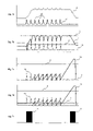
- FIG. 5 a FIG. 7 a : with sustained dynamic strain, the pressure curve in the cuff and in the urinary bladder upon short-term dynamic strain;
- FIG. 5 b FIG. 7 b : with sustained dynamic strain, the signal curve of the electronic circuit upon short-term dynamic strain;
- FIG. 5 c FIG. 7 c : with sustained dynamic strain, the signal curve of the integrator system with the output signal of the differentiator function as the input signal of the integrator function upon short-term dynamic strain;
- FIG. 5 d FIG. 7 d : with sustained dynamic strain, the signal curve of the integrator system with the output signal of the adding function as the input signal of the integrator function upon short-term dynamic strain;
- FIG. 5 e FIG. 7 e : with sustained dynamic strain, the switching conditions for pressure increase and pressure decrease in the cuff in case of short-term dynamic strain;
- FIG. 6 a FIG. 8 a : with sustained dynamic strain, the pressure curve in the cuff, in the urinary bladder and the admission pressure reservoir upon short-term dynamic strain;
- FIG. 6 b FIG. 8 b : with sustained dynamic strain, the signal curve of the electronic circuit upon short-term dynamic strain;
- FIG. 6 c 8 c : with sustained dynamic strain, the signal curve of the integrator system with the output signal of the differentiator function as the input signal of the integrator function upon short-term dynamic strain;
- FIG. 6 d FIG. 8 d : with sustained dynamic strain, the signal curve of the integrator system with the output signal of the adding function as the input signal of the integrator function upon short-term dynamic strain;
- FIG. 6 e FIG. 8 e : with sustained dynamic strain, the switching conditions for pressure increase and pressure decrease in the cuff upon short-term dynamic strain;
- FIG. 6 f FIG. 8 f : with sustained dynamic strain, the switching conditions for pressure increase in the admission pressure reservoir;
- FIG. 6 g FIG. 8 g : with sustained dynamic strain, the course of the integrator signal for controlling the opening of the valve between cuff and admission pressure reservoir;
- FIG. 9 a the integrator signal with switching threshold upon sustained dynamic strain
- FIG. 9 b the input signals of the integrator function with areas of progressive ( 22 ) and retrogressive ( 21 ) integration upon sustained dynamic strain;
- FIG. 10 the method for regulation of the urethra closing pressure without admission pressure reservoir
- FIG. 11 the method for regulation of the urethra closing pressure with admission pressure reservoir
- FIG. 12 the signal curve upon dynamic strain, namely 12 a absolute pressures, 12 b the urethra closing pressure signal with switching thresholds and 12 c the integrator signal with switching thresholds (or, respectively, integrator system or, respectively, integrator element); and
- FIG. 13 a functional schematic presentation of the artificial sphincter implant.
- a digital as well as analog realization of the electronic control of the sphincter implant is possible. This will not basically change the method for controlling the sphincter implant which is the subject of this invention.
- D/A converters are used whose clock signal is externally generated and can be transmitted via telemetry.
- the electronic control which is the subject of this invention converts fine-sensory signals, especially the differential pressure between urinary bladder and cuff or a comparable differential pressure, into control commands to the actuator system of the implant.
- the sensor signals applied on the signal inputs are amplified by means of amplifier circuitry such that the signals will operate between the limit values specified by the circuitry.
- the cuff pressure ( 4 ) operates in a range in which the blood circulation of the urethra tissue is ensured, which could, however, easily result in incontinence upon an increase of the internal bladder pressure ( 11 ). If the differential pressure signal or, respectively, the differential pressure value ( 1 ) increases, the cuff pressure ( 4 ) will decrease ( 16 ) upon reaching a bistable threshold value ( 3 ); if the differential pressure signal or, respectively, the differential pressure value ( 1 ) drops below the lowered bistable threshold value ( 3 ), the decrease ( 16 ) of the cuff pressure ( 4 ) will be terminated. For the analog variant, this is done by means of a comparator function which is provided with a hysteresis circuit.
- the actuator system must take over the function of a healthy sphincter, that is prevent incontinence in case of dynamic strain, through active pressure transmission, thus the involuntary contraction of the sphincter.
- the cuff pressure ( 4 ) must be increased within milliseconds. Since incontinence can be assumed at a differential pressure of zero, the actuator system will be caused to increase ( 15 ) the cuff pressure ( 4 ) if the differential pressure signal or, respectively, the differential pressure value ( 1 ) drops below a threshold value which is different from zero.
- the electronic control system is designed to provide this lower threshold value—under which the differential pressure signal or, respectively, the differential pressure value ( 1 ) may drop upon miction only—with an additive active component.
- the differential pressure signal ( 1 ) it is differentiated by means of a differentiator circuit, and the output signal or, respectively, the output value ( 14 ) of the differentiator function is increased by the lower threshold value by means of an adding circuit.
- the sensor signal is numerically differentiated by subtracting the current signal value from the penultimate signal value, and the result, if positive, will be added with an offset component.
- the lower threshold value ( 12 ) The result serves as the lower threshold value ( 12 ).
- the lower threshold value ( 12 ) upon a sudden increase of the internal bladder pressure ( 11 )—runs counter to the sinking differential pressure signal or, respectively, the differential pressure value ( 1 ) and thus enables early activation of the actuator system.
- the actuator system is activated by means of a comparator which compares the differential pressure signal ( 1 ) with the lower threshold value ( 12 ).
- the comparator function is deactivated with the analog variant to avoid an excessive cuff pressure ( 4 ) in non-strained operation, and the cuff pressure ( 4 ) is increased to a value at which continence can be ensured, yet the blood circulation of the urethra tissue concerned may be impaired.
- this pressure increase may be implemented in different ways:
- a valve ( 26 ) When using an admission pressure reservoir ( 29 ), a valve ( 26 ) is opened so that a pressure compensation can take place between the admission pressure reservoir ( 29 ) and the cuff ( 25 ). Due to the fluid flow with this pressure compensation, the admission pressure ( 17 ) set beforehand must be higher by a certain amount than the desired maximum cuff pressure, depending on the design of the cuff ( 25 ) and the admission pressure reservoir ( 29 ).
- the valve between the admission pressure reservoir ( 29 ) and the cuff ( 25 ) is opened time-controlled.
- an integrator element can here be especially used which is started simultaneously with the opening of the valve and whose output signal ( 19 ) is compared by means of a comparator element with a monostable threshold value ( 10 ).
- the valve ( 26 ) between the admission pressure reservoir ( 29 ) and the cuff ( 25 ) When reaching parity, the valve ( 26 ) between the admission pressure reservoir ( 29 ) and the cuff ( 25 ) will be closed again and, at the same time, the increase ( 18 ) of the admission pressure ( 17 ) is started in the admission pressure reservoir ( 29 ).
- Activation of the integrator element which—for the analog variant—controls the decrease ( 16 ) of the cuff pressure ( 25 ) occurs either simultaneously with the opening or with the closing of the valve ( 26 ) between the admission pressure reservoir ( 29 ) and the cuff ( 25 ).
- the signal causing the valve ( 26 ) between the admission pressure reservoir ( 29 ) and the cuff ( 25 ) to close will trigger the increase ( 18 ) of the admission pressure ( 17 ) in the admission pressure reservoir ( 29 ).
- the pressure signal of the admission pressure ( 17 ) which is additionally required with the application of an admission pressure reservoir ( 29 ) will be compared—for the analog variant—with a monostable threshold value ( 8 ) by means of a comparator element and, in case of parity, a signal is triggered which causes termination of the increase ( 18 ) of the admission pressure ( 17 ).
- a microprocessor When a microprocessor is used, it will be programmed such that it will principally act like the described analog circuit.
- Activation of the integrator element which controls—for the analog variant—the decrease ( 16 ) of the cuff pressure ( 4 ) can in particular be done via the interruption of a discharge circuit of the condenser with negative feedback operational amplifier of the integrator element.
- integration can take place and the starting value is equivalent to the tension over the discharged condenser.
- the electronic circuitry's intelligence is especially manifest in that the decrease ( 16 ) of the cuff pressure ( 4 ) will be delayed upon sustained dynamic strain.
- an integrator element is used for this.
- a suitable selection of the input signals will achieve that—in case of short-term strain, for example when getting up from a sitting position—the cuff pressure ( 4 ) is relatively fast decreased again to values which correspond with a safe normal operation without the risk of necrosis.
- sustained dynamic strain for example with physical activities—the cuff pressure ( 4 ) is kept so long at a high level until the dynamic strain abates.
- this behavior is generated by applying two suitable signals on the inverting and non-inverting input of the operation amplifier of the integrator element.
- this is a signal which is analog to the output signal ( 14 ) of the differentiator element, especially either the output signal ( 14 ) of the differentiator element itself or the output signal ( 12 ) of the adding element.
- a monostable reference signal ( 5 ) At the other input of the operation amplifier of the integrator element, there is a monostable reference signal ( 5 ). This monostable reference signal ( 5 ) is selected such that it can be crossed by the signal applied at the other input of the operation amplifier of the integrator element upon dynamic strain and thus volatile output signal ( 14 ) of the differentiator element.
- This circuiting of the integrator element has the consequence that the output signal ( 13 ) of the integrator element moves away from the starting point if the input signal which is analog to the output signal ( 14 ) of the differentiator element has not or rarely crossed the monostable reference signal ( 5 ), thus in case of a low dynamic of strain.
- the input signal analog to the output signal ( 14 ) of the differentiator element frequently crosses the monostable reference signal ( 5 ).
- the output signal ( 13 ) of the integrator element moves toward the starting value.
- the output signal ( 13 ) of the integrator element is driven in zigzag fashion toward the starting value.
- a comparator element will compare the output signal ( 13 ) of the integrator element with a constant threshold value ( 6 ) which may not be in the proximity of the starting value of the output signal ( 13 ) of the integrator element. As soon as the output signal ( 13 ) of the integrator element reaches this constant threshold value ( 6 ), a decrease ( 16 ) of the cuff pressure ( 4 ) is caused.
- Another vital characteristic of this electronic control is the presence of a plurality of possibilities to influence the system's behavior from the outside through a variation of parameters.
- the artificial fine-sensory sphincter implant can thereby be adjusted to the patient's individual requirements—on the one hand, setting the parameters after scarring is completed after the implantation; on the other hand, in case of changing requirements by the patient, for example with progressing age or a changed way of life.
- the monostable offset signal is the additive component which supplements the output signal ( 14 ) of the differentiator element to the lower circuit threshold.
- the bistable threshold signal ( 3 ) can be varied if the cuff pressure ( 4 ) in normal operation already reaches critical values for the blood circulation of the urethra tissue, or if the bistable threshold signal ( 3 ) is adjusted so low that the decrease ( 16 ) of the cuff pressure ( 4 ) is caused unreasonably frequently.
- the speed of integration can be adjusted.
- the monostable threshold signal ( 2 ) is equivalent to the differential pressure signal or, respectively, the differential pressure value ( 1 ) at which the cuff pressure ( 4 ) has a value which ensures continence, where the blood circulation of the urethra tissue is impaired, however. If the monostable threshold signal ( 2 ) is too low, the differential pressure signal or, respectively, the differential pressure value ( 1 ) can fall below the lower circuit threshold—despite increased cuff pressure ( 4 ) in case of a high dynamic strain—and thus trigger a further pressure increase. With a monostable threshold signal ( 2 ) which is adjusted too high, the urethra tissue may be damaged due to the excessive cuff pressure ( 4 ); or
- the admission pressure in the admission pressure reservoir and thus the maximum cuff pressure ( 4 ) is adjusted after pressure compensation.
- the actuator system controlled by the described analog circuit can avail itself of various methods and arrangements to produce the desired influence on the urethra.
- the different arrangements and components of the actuator system require matched control electronics.
- Two hydraulic methods are described hereinafter by way of example—one with and one without an admission pressure reservoir ( 29 ).
- an admission pressure reservoir ( 29 ) in this method enables a flash-like increase ( 15 ) of the cuff pressure ( 4 ).
- another pressure sensor will be required which controls the regulation of the admission pressure ( 17 ).
- a pressure compensation will be enabled by opening the valve ( 26 ) between the admission pressure reservoir ( 29 ) and the cuff ( 25 ).
- the safety pressure in the cuff ( 25 ) only depends on the admission pressure ( 17 ) adjusted beforehand in the admission pressure reservoir ( 29 ).
- Also decisive for the pressure compensation is the design of the admission pressure reservoir ( 29 ). The smaller the dimensions, the larger the admission pressure ( 17 ) must be.
- a signal is generated externally. This signal causes the actuator system to decrease ( 16 ) the cuff pressure ( 4 ) and, moreover, it deactivates the analog electronic circuit except for the comparator element which limits the normal cuff pressure to the top.
- a second external signal is generated which again initiates the increase ( 15 ) of the cuff pressure ( 4 ).
- the cuff pressure ( 4 ) will be increased until the differential pressure signal or, respectively, the differential pressure value ( 1 ) reaches the bistable threshold value ( 3 ).
- the remaining analog electronic circuit will thus be reactivated.
- this aspect of the invention thus comprises the following embodiments:
- the method for the electronic control of an artificial fine-sensory sphincter implant is characterized in that the behavior of at least one sensor signal in an analog or digital electronic circuit will be converted such by means of calculator and comparator functions and compared with reference values such that an actuator system will be controlled such that the cuff pressure or, respectively, the differential pressure between the cuff and the urinary bladder will move either in a low range, limited by two threshold values, or above a specific safety pressure.
- the sensor signal or, respectively, the sensor value ( 1 ) of the electronic circuit according to embodiment 1 is characterized in that it behaves analog the difference between the internal bladder pressure ( 11 ) and the cuff pressure ( 4 ).
- the differentiator function of the electronic circuit according to embodiment 1 is characterized in that the output signal or, respectively, the output value ( 14 ) of the differentiator function is in accordance with the differentiation of the course of the sensor signal ( 1 ) according to embodiment 2.
- the adding function with a monostable offset signal or, respectively, offset value of the electronic circuit according to embodiment 1 is characterized in that the output signal or, respectively, the output value ( 12 ) of the adding function is in accordance with the output signal or, respectively, output value ( 14 ) of the differentiator function according to embodiment 3, increased by a monostable offset signal or, respectively, a monostable offset value.
- the comparator function with a bistable threshold signal or, respectively, threshold value ( 3 ) of the electronic circuit according to embodiment 1 is characterized in that—in the event of parity or, respectively, crossing of the sensor signal or, respectively, the sensor value ( 1 ) according to embodiment 2 with the bistable threshold signal or, respectively, with the bistable threshold value ( 3 )—this threshold signal or, respectively, this threshold value ( 3 ) will be decreased or, respectively, increased by the amount due to hysteresis and a signal will be triggered which causes the actuator system to decrease ( 16 ) the cuff pressure ( 4 ) until a signal is triggered—due to the renewed parity or, respectively, renewed crossing of the sensor signal ( 1 ) according to embodiment 2 with the bistable threshold signal or, respectively, the bistable threshold value—which causes the actuator system to terminate the decrease ( 16 ) of the cuff pressure ( 4 ) and will increase or, respectively, decrease the bistable threshold signal or, respectively, the bistable threshold value ( 3 ) by the amount due to
- the comparator function of the electronic circuit according to embodiment 1 is characterized in that the sensor signal or, respectively, the sensor value ( 1 ) according to embodiment 2 is compared with the output signal or, respectively, the output value ( 12 ) of the adding function according to embodiment 4 such that—in the event of parity or, respectively, crossing of the sensor signal or, respectively, the sensor value ( 1 ) according to embodiment 2 with the output signal or the output value ( 12 ) of the adding function according to embodiment 4—a signal will be triggered which causes the actuator system to increase ( 15 ) the cuff pressure ( 4 ) and deactivates the comparator function according to embodiment 5.
- the integrator function with a monostable reference signal or, respectively, a monostable reference value ( 5 ) and a constant starting value of the electronic circuit according to embodiment 1 is characterized in that optionally
- the delay function of the electronic circuit according to embodiment 1 when using a method for the regulation of the cuff pressure ( 4 ) with admission pressure reservoir ( 29 ) is characterized in that, upon triggering the pressure compensation between the admission pressure reservoir ( 29 ) and the cuff ( 25 ) by the comparator function according to embodiment 6, the delay function will be activated and upon reaching the set delay time, a signal is triggered which causes the actuator system to terminate the pressure compensation between the admission pressure reservoir ( 29 ) and the cuff ( 25 ) and activates the integrator function according to embodiment 7 such that, upon activation, the output signal or, respectively, the output value ( 13 ) of the integrator function according to embodiment 7 is in accordance with the constant starting value according to embodiment 7.
- the comparator function with a monostable threshold signal or, respectively, threshold value ( 2 ) of the electronic circuit according to embodiment 1 is characterized in that—in the event of parity or, respectively, crossing of the sensor signal or, respectively, sensor value ( 1 ) according to embodiment 2 with the monostable threshold signal or, respectively, the monostable threshold value ( 2 )—a signal is triggered which causes the actuator system to terminate the increase ( 15 ) of the cuff pressure ( 4 ) and activates the integrator function according to embodiment 7 such that, upon activation, the output signal or, respectively, the output value ( 13 ) of the integrator function according to embodiment 7 will be in accordance with the constant starting value according to embodiment 7.
- the comparator function with a monostable threshold signal or, respectively, a monostable threshold value ( 6 ) of the electronic circuit according to embodiment 1 is characterized in that—in the event of parity or, respectively, crossing of the output signal or, respectively, the output value ( 13 ) of the integrator function according to embodiment 7 with the monostable threshold signal or, respectively, threshold value ( 6 )—a signal is triggered which causes the actuator system to decrease ( 16 ) the cuff pressure ( 4 ) and/or activates the comparator function according to embodiment 5.
- the monostable offset signal or, respectively, the monostable offset value according to embodiment 4 is characterized in that it can be varied by parameter variation from the outside.
- the bistable threshold signal or, respectively, the bistable threshold value ( 3 ) according to embodiment 5 is characterized in that it can be varied by parameter variation from the outside.
- the monostable reference signal or, respectively, the monostable reference value ( 5 ) according to embodiment 7 is characterized in that it can be varied by parameter variation from the outside.
- the monostable threshold signal or, respectively, the monostable threshold value ( 2 ) according to embodiment 9 is characterized in that it can be varied by parameter variation from the outside.
- the method of the electronic circuit for the control of miction according to embodiment 1 is characterized in that, for activation of miction, an external signal causes the actuator system to decrease the urethra closing pressure and deactivates the electronic circuit according to embodiment 1 expect for the comparator function according to embodiment 5, and for deactivation of miction, an external signal causes the actuator system to increase ( 15 ) the cuff pressure ( 4 ) until a signal is triggered—in the event of parity or, respectively, crossing of the sensor signal ( 1 ) according to embodiment 2 with the bistable threshold signal or, respectively, threshold value ( 3 ) according to embodiment 5—which activates the electronic circuit according to embodiment 1.
- This invention presents a novel fine-sensory implant which combines the most important aspects of technological issues of in vivo medical technology: a reliable fine sensory system; intelligent, flexible control electronics with low power consumption; a miniaturized and powerful actuator system, as well as sophisticated energy and data transmission.
- a reliable fine sensory system intelligent, flexible control electronics with low power consumption
- a miniaturized and powerful actuator system as well as sophisticated energy and data transmission.
- an artificial, adaptive, fine-sensory sphincter the current state of the art of implantation technology will be discussed before the background of its development history and the methodical development of criteria for selection control and alternative design, including intensive tests for the determination of individual components, simultaneously taking comparable implants into account.
- a current system of an artificial bladder neck sphincter uses a hand pump in the scrotum or, respectively, the labia majora, which is used to pump up the collar which blocks the flow of urine and is placed around the urethra [ 6 ].
- the setting of the urethra closing pressure is problematical with this system. Insufficient pressure results in involuntary discharge of urine upon dynamic strain which can be caused by laughing, coughing, sneezing or heavy lifting. Excessive pressure on the urethra over a long period of time can readily result in black tissue, i.e. necrosis. To avoid this risk, the practice has so far been to rather accept a slight strain incontinence with all its negative social consequences.
- the artificial fine-sensory sphincter implant which has been developed in accordance with the invention replaces the hand pump by active hydraulics, equipped with a fine sensory system and intelligent controls.
- This system can support or replace active pressure transmission.
- the sensory system primarily monitors the difference between internal bladder pressure and cuff pressure.
- the actuator system is used to increase the cuff pressure so that continence will be ensured even at these increased pressure conditions. Normal blood circulation of the urethra tissue can thereby be impaired for a short term.
- the implant is able to distinguish between single-action strain and sustained dynamic strain.
- the decisive factor for the function of the artificial fine-sensory sphincter implant is the urethra closing pressure ( 31 ). If the urethra closing pressure ( 31 ) is negative, urine discharge will occur.
- the signal which is equivalent to the urethra closing pressure ( 31 ) is ascertained from the two absolute pressure signals of the cuff ( 25 ) and the urinary bladder ( FIG. 12 a ). In case of suddenly arising dynamic strain in the peritoneal cavity, this signal goes fast toward zero. To ensure a fast reaction of the implant in this situation, the following measures are taken:
- Lowering of the urethra closing pressure ( 31 ) is limited toward the bottom by a switching threshold which is above the incontinence range and can be varied in programming.
- the response of the urethra closing pressure ( 31 ) will be differentiated and the positive portion added to the lower switching threshold ( 12 ).
- the actuator system is activated by means of a comparator which compares the signal of the urethra closing pressure ( 31 ) with the lower switching threshold ( 12 ).
- admission pressure reservoir enables a flash-like reaction of the actuator system with little supply voltage.
- admission pressure ( 17 ) is increased to a variable maximum value p max (within t 2 to t 3 ).
- the increased cuff pressure is decreased, microprocessor-controlled, under the normal pressure threshold ( 3 ) provided with a hysteresis.
- the difference of an offset value ( 5 ) which can also be varied in programming, and the lower switching threshold ( 12 ) will be integrated.
- the integration result ( 13 ) is pressed downwardly in zigzag shape. Without dynamic strain, the integration result ( 13 ) increases up to a threshold value ( 6 ), and when this is reached, the reduction of the cuff pressure will be triggered (t 4 ) ( FIG. 12 c ).
- the normal pressure threshold prevents an excessive cuff pressure in normal operation. Like the activation of the actuator system, this function will also be realized with analog electronic components.
- the analog circuit comprises 4 variable parameters which are influenced by means of D/A converters, namely: the speed of differentiation of the urethra closing pressure signal, the additive offset component of the lower threshold value, as well as the mean value and the hysteresis of the normal pressure threshold.
- the permanently activated electronics will be limited to a minimum of 6 operation amplifiers and a quad-digital potentiometer of the analog circuit, as well as to the signal conditioning and the RF receiver module.
- the electronics complete power consumption is under 0.1 mW, with the microprocessor in power-down mode.
- the artificial fine-sensory sphincter implant according to the invention is programmed by means of an external programming station. Via a bi-directional transcutaneous data transfer, the urethra closing pressure as well as the absolute pressure in the admission pressure reservoir are transmitted into the programming station.
- the in vivo pressure measurement in combination with a simultaneous external urodynamic examination enables largely automated implant programming.
- the patient performs defined physical actions; for example, getting up from a sitting position or coughing. From the collected measuring data together with empirical values from clinical tests, the software can evaluate an optimal setting of the implant. Subsequently required adjustments of the programming are also manually possible, for example with regard to the patient's changed living conditions or a changed behavior of the implanted electronics.
- This capacitive pressure sensor consists of a polysilicon membrane and a silicon substrate [ 1 ]. During manufacture, a vacuum is produced between the polysilicon membrane and the silicon substrate so that an absolute pressure sensor is developed. With the minor diameter of 100–120 ⁇ m of a sensor element, a sensor array connected in parallel can be set up for signal amplification [ 2 ].
- the absolute pressure in the cuff can also be measured by means of a differential pressure sensor which measures the difference between cuff and admission pressure.
- a differential pressure sensor which measures the difference between cuff and admission pressure.
- the absolute pressure signal of the cuff pressure can be filtered from the absolute pressure signal of the admission pressure reservoir and the differential pressure signal between cuff and admission pressure reservoir. This enables the use of an inexpensive and reliable piezo-resistive differential pressure sensor which is connected via hydraulic connections with the admission pressure reservoir as well as with the cuff.
- an absolute pressure sensor similar to a brain pressure probe—is embedded in the tissue in the vicinity of the bladder so that the urinary bladder need not be punctured or opened [ 5 ].
- the measured pressure will possibly not be exactly the same as the internal bladder pressure but it will be equivalent.
- the physical dimensions as well as the power consumption of the electronic components are not the critical parameters since both are negligible in comparison with the properties of the actuator system. Nonetheless, minimization is aimed at although more importance may be attached to reliability and redundant systems.
- control electronics specified for the artificial fine-sensory sphincter implant are similar to those of a modern pacemaker. As in a pacemaker, sensor signals from a microprocessor are analyzed and converted into implant actions. To minimize the electronics power consumption, the microprocessor is normally operated in power-down mode. The comparator which activates the actuator system upon dynamic strain simultaneously activates the microprocessor.
- microprocessor programmable via transcutaneous data transmission has the fundamental advantage that it can flexibly react to any changes, for example in the patient's habits or in the behavior of electronic components.
- analog semiconductor components for example as a calculator circuit to determine the absolute cuff pressure, will thus be less critical.
- the analog components can be permanently activated without any problem.
- the only intermittently active microprocessor can be operated with relatively high clock frequencies since the connected relatively high power consumption can be easily compensated by a considerably improved performance of the implant.
- the signal conditioning, the analog circuit, the A/D converter, the internal memory and the microprocessor with a multi-I/O module can be combined in a mixed signal ASIC, an application-specific integrated circuit [ 4 ].
- This offers extremely low power consumption since—in contrast to the use of a commercial microprocessor—no unused features lie fallow yet still use power.
- This advantage is confronted with high development expenditures which lead to the desired result via design, simulation and manufacturing. For this reason, the implant prototype is realized with a commercial microcontroller.
- the development of an ASCI for a prototype would be a disproportionately high expenditure of time and finances.
- the source of energy is a lithium-ion accumulator which is charged via a subcutaneously implanted induction coil.
- the charge controller of the lithium-ion battery pack is a commercial IC as it is used for example in mobile phones. It monitors the current flow between the energy transfer module and the battery which it can influence with a MOSFET. Termination, abort and fault will be reported to the microprocessor.
- the actuator system of the artificial fine-sensory sphincter implant consists of electrically active components, the valves and the pump, and of passive components, an admission pressure chamber, an inflatable cuff and the hydraulic connections ( FIG. 13 ). These components must be specially adapted for use in the artificial fine-sensory sphincter implant. Industrial pumps and valves are mostly designed for pressures of 10 bar and more. Since maximum pressures of under 500 mbar occur in the implant, adjusted dimensioning of these components makes good sense.
- the admission pressure reservoir consists of a rigid base plate over which an elastic membrane is stretched. Due to the flat structure, the admission pressure reservoir can be integrated into the outer shell of the implant such that the elastic membrane can bulge outwardly in case of a pressure increase.
- the decisive function of the artificial fine-sensory sphincter implant is the flash-like increase of the cuff pressure in case of a sudden drop in the urethra closing pressure.
- an increased admission pressure will be provided which can be transmitted to the cuff via valve 3 . Since the electronic system reaches reaction times within the microsecond to nanosecond range, the decisive gain in reaction time is to be expected with an optimization of the system of admission pressure reservoir, valve 3 and the hydraulic connection.
- Reaction times of under 10 ms are realizable from activating the actuator system until termination of the pressure compensation.
- the mass inertia of the valve 3 will cause a further delay which increases with an increasing opening radius r.
- the cuff pressure is reduced via valve 2 in the reservoir.
- care must be taken that the cuff pressure is not reduced too fast. If this is the case, increase of the cuff pressure can be immediately triggered again due to the valve inertia and the oncoming lower switching threshold. However, this risk can be avoided with an appropriate selection of the cross-section opening of the hydraulic connections.
- the energy and data transmission it has the most things in common with the artificial urinary bladder [ 6 ] [ 7 ] [ 8 ].
- the energy transmission for the artificial fine-sensory sphincter implant only serves to load the implanted battery and data transmission is mainly used for programming the microprocessor.
- data transmission is mainly used for programming the microprocessor.
- miction control another signal path is used which is uncomplicated to operate for the patient. From these framework conditions, the following configuration of energy and data transmission was designed for use in the artificial fine-sensory sphincter implant:
- the implanted battery is charged inductively by placing a charger onto a subcutaneously implanted induction coil [ 3 ].
- a charger onto a subcutaneously implanted induction coil [ 3 ].
- an IR sending/receiving module was placed in the middle of the induction coil. This optical data transmission requires—like inductive energy transmission—that the external counterpart is placed directly on the skin.
- this function can be integrated into the external charger.
- the miction is controlled via unidirectional RF data transmission. This enables the patient a comfortable and uncomplicated operation of the implant. Transmitted will be the miction desire as well as a signal for terminating miction.
Abstract
Description
- (1) Differential pressure signal, bladder/cuff pressure difference
- (2) Monostable threshold signal, safety threshold
- (3) Bistable threshold signal, normal pressure threshold
- (4) Cuff pressure
- (5) Monostable reference signal, zero integration offset
- (6) Monostable threshold signal, integration threshold
- (7) Admission pressure signal
- (8) Monostable threshold signal, admission pressure threshold
- (9) Dynamic strain
- (10) Monostable threshold signal, pressure compensation threshold
- (11) Internal bladder pressure
- (12) Output signal or, respectively, output value of the adding function, lower threshold value
- (13) Output signal or, respectively, output value of the integrator function
- (14) Output signal or, respectively, output value of the differentiator function
- (15) Increase of cuff pressure
- (16) Decrease of cuff pressure
- (17) Admission pressure
- (18) Increase of admission pressure
- (19) Output signal of the integrator function of the delay block
- (20) Dynamic strain
- (21) Area of retrogressive integration
- (22) Area of progressive integration
- (23) Method for regulating the urethra closing pressure by means of an inflatable cuff, a fluid reservoir, a pump, and a valve via hydraulic connections
- (24) Hydraulic connection
- (25) Cuff
- (26) Controllable valve
- (27) Bi-directional pump
- (28) Fluid reservoir
- (29) Admission pressure reservoir
- (30) Method for regulating the urethra closing pressure by means of an inflatable cuff, a fluid reservoir, a pump, three valves and an admission pressure reservoir via hydraulic connections
- (31) Urethra closing pressure
- (32) Differentiator function
- (33) Adding function
- (34) Integrator function
- (35) Parameter variation
- (36) Comparator element
- (37) Integrator function of the delay block
- a) the monostable reference signal or, respectively, the monostable reference value (5) is unequal to the monostable offset signal or, respectively, the offset value according to
embodiment 4 and is selected such that the output signal or, respectively, the output value (12) of the adding function according toembodiment 4 upon activity will cross the monostable reference signal or, respectively, the monostable reference value (5), and that the integrator function will continuously or numerically integrate the difference between the output signal or, respectively, the output value (12) of the adding function according toembodiment 4 and the monostable reference signal or, respectively, the monostable reference value (5) such that with a low activity of the output signal or, respectively, the output value (14) of the differentiator function according toembodiment 3, the output signal or, respectively, the output value (13) of the integrator function will move away from the starting value and upon high activity of the output signal or, respectively, the output value (14) of the differentiator function according toembodiment 3, will move toward the starting value, seeFIG. 1 d,FIG. 2 d,FIG. 3 d,FIG. 4 d andFIG. 5 ; or - b) the monostable reference signal or, respectively, the monostable reference value (5) is unequal to the output signal or, respectively, the output value (14) of the differentiator function according to
embodiment 3 upon low activity and is selected such that the output signal or, respectively, the output value (14) of the differentiator function according toembodiment 3 upon activity will cross the monostable reference signal or, respectively, the monostable reference value (5), and that the integrator function will continuously or numerically integrate the difference between the output signal or, respectively, the output value (14) of the differentiator function according toembodiment 3 and the monostable reference signal or, respectively, the monostable reference value (5) such that, upon low activity of the output signal or, respectively, the output value (14) of the differentiator function according toembodiment 3, the output signal or, respectively, the output value (13) of the integrator function will continuously move away from the starting value and upon high activity of the output signal or, respectively, of the output value (14) of the differentiator function according toembodiment 3 will move towards the starting value, seeFIG. 1 c,FIG. 2 c,FIG. 3 c,FIG. 4 c andFIG. 5 .
- [1] M. Kandler, J. Eichholz, Y. Manoli, W. Mokwa, “CMOS compatible capacitive pressure sensor with readout electronics”, International Conference on Micro Electro, Opto, Mechanic Systems and Components, Micro System Technologies, pp. 574–580, 1990
- [2] H. Dudaicevs, Y. Manoli, W. Mokwa, M. Schmidt, E. Spiegel, “A fully integrated surface micromachined pressure sensor with low temperature dependence”, Transducers, Digest of technical papers, pp. 616–619, 1995
- [3] H. Wassermann, “Drahtlose Energie- und Signalübertragung mit gleichzeitiger Disloziervorkehrung und -vorrichtung bei Unzugänglichkeit einer Seite und bei undurchsichtigem Dielektrikum”, Technisches FB-Kompendium, 1992
- [4] R. Lerch, E. Spiegel, R. Kakerow, R. Hakenes, H. Kappert, H. Kohlhaas, N. Kordas, M. Buchmann, T. Franke, Y. Manoli, J. Müller, “A programmable mixed-signal ASIC for data-acquisition systems in medical implants”, International Solid-State Circuits Conference, Digest of technical papers, pp. 160–161, 1995
- [5] A. Atala, M. R. Freeman, J. P. Vacanti, J. Shepard, A. B. Retik, “Implantation in vivo and retrieval of artificial structures consisting of rabbit and human urothelium and human bladder muscle”, J. Urol. 150, pp. 608–612, 1993
- [6] D. Jocham and K. Miller “Praxis der Urologie II”, Stuttgart: Georg Thieme, 1994/2002
- [7] H. Wassermann, “Künstliches harnableitendes System”, Medizintechnik in Bayern, vol. 2, pp. 57–61, 2002
- [8] R. Stölting, “Künstliche Harnblase—Klinische Tests stehen noch aus”, medizin report,
vol 2, pp. 22–23 - [9] H. Wassermann, “Artificial Urinary Diversion System”, Bavarian Medical Technologies, vol. 2, pp. 53–57, 2002
Claims (30)
Applications Claiming Priority (7)
| Application Number | Priority Date | Filing Date | Title |
|---|---|---|---|
| DE10156558 | 2001-11-20 | ||
| DE2001156558 DE10156558A1 (en) | 2001-11-20 | 2001-11-20 | Implantable system opening and closing tubular organ has control system reverting automatically to first state |
| DE10156558.5 | 2001-11-20 | ||
| DE10239309 | 2002-08-27 | ||
| DE2002139309 DE10239309B4 (en) | 2002-08-27 | 2002-08-27 | Method and system for the electronic control of an artificial fine-sensory sphincter implant |
| DE10239309.5 | 2002-08-27 | ||
| PCT/EP2002/012963 WO2003043534A2 (en) | 2001-11-20 | 2002-11-19 | Closing system and electronic control method |
Publications (2)
| Publication Number | Publication Date |
|---|---|
| US20050240144A1 US20050240144A1 (en) | 2005-10-27 |
| US7217237B2 true US7217237B2 (en) | 2007-05-15 |
Family
ID=26010600
Family Applications (1)
| Application Number | Title | Priority Date | Filing Date |
|---|---|---|---|
| US10/496,423 Expired - Fee Related US7217237B2 (en) | 2001-11-20 | 2002-11-19 | Closing system and electronic control method |
Country Status (7)
| Country | Link |
|---|---|
| US (1) | US7217237B2 (en) |
| EP (2) | EP2123238A1 (en) |
| AT (1) | ATE421300T1 (en) |
| AU (1) | AU2002352060B2 (en) |
| DE (1) | DE50213247D1 (en) |
| DK (1) | DK1513466T3 (en) |
| WO (1) | WO2003043534A2 (en) |
Cited By (12)
| Publication number | Priority date | Publication date | Assignee | Title |
|---|---|---|---|---|
| EP2074971A1 (en) * | 2007-12-27 | 2009-07-01 | Ethicon Endo-Surgery, Inc. | Fluid logic for regulating restriction devices |
| WO2009094431A2 (en) * | 2008-01-23 | 2009-07-30 | Ams Research Corporation | Inflatable medical implant system |
| US20110124955A1 (en) * | 2007-08-24 | 2011-05-26 | Universite Joseph Fourier-Grenoble 1 | Device to prevent urinary leakage |
| US8380312B2 (en) | 2009-12-31 | 2013-02-19 | Ams Research Corporation | Multi-zone stimulation implant system and method |
| US8449512B2 (en) | 2010-04-09 | 2013-05-28 | Davinci Biomedical Research Products Inc. | Stoma stabilitating device and method |
| US20150374288A1 (en) * | 2013-02-01 | 2015-12-31 | Uromems | System and method for detecting an endo-urethral device for an artificial sphincter that is implantable in an animal or human body |
| US9731112B2 (en) | 2011-09-08 | 2017-08-15 | Paul J. Gindele | Implantable electrode assembly |
| US10350044B2 (en) * | 2014-11-25 | 2019-07-16 | Uromems | Implantable occlusion system |
| US11000227B2 (en) * | 2016-03-29 | 2021-05-11 | Avita Corporation | Measurement device and method for measuring psychology stress index and blood pressure |
| US11129700B2 (en) * | 2016-06-14 | 2021-09-28 | A.M.I. Agency For Medical Innovations Gmbh | Medical arrangement for shutting off a body channel |
| US11197748B2 (en) | 2016-06-03 | 2021-12-14 | A.M.I. Agency For Medical Innovations Gmbh | Medical device for narrowing or closing an anatomical channel |
| US11207163B2 (en) | 2016-06-14 | 2021-12-28 | A.M.I. Agency For Medical Innovations Gmbh | Medical arrangement for shutting off a body channel |
Families Citing this family (16)
| Publication number | Priority date | Publication date | Assignee | Title |
|---|---|---|---|---|
| FR2878733B1 (en) * | 2004-12-08 | 2007-03-30 | Francis Bartolome | MEDICAL DEVICE IMPLANTED REMOTE CONTROL |
| US7775966B2 (en) | 2005-02-24 | 2010-08-17 | Ethicon Endo-Surgery, Inc. | Non-invasive pressure measurement in a fluid adjustable restrictive device |
| US7927270B2 (en) | 2005-02-24 | 2011-04-19 | Ethicon Endo-Surgery, Inc. | External mechanical pressure sensor for gastric band pressure measurements |
| US7658196B2 (en) | 2005-02-24 | 2010-02-09 | Ethicon Endo-Surgery, Inc. | System and method for determining implanted device orientation |
| US8066629B2 (en) | 2005-02-24 | 2011-11-29 | Ethicon Endo-Surgery, Inc. | Apparatus for adjustment and sensing of gastric band pressure |
| US8016744B2 (en) | 2005-02-24 | 2011-09-13 | Ethicon Endo-Surgery, Inc. | External pressure-based gastric band adjustment system and method |
| US7775215B2 (en) | 2005-02-24 | 2010-08-17 | Ethicon Endo-Surgery, Inc. | System and method for determining implanted device positioning and obtaining pressure data |
| US7699770B2 (en) * | 2005-02-24 | 2010-04-20 | Ethicon Endo-Surgery, Inc. | Device for non-invasive measurement of fluid pressure in an adjustable restriction device |
| US8152710B2 (en) | 2006-04-06 | 2012-04-10 | Ethicon Endo-Surgery, Inc. | Physiological parameter analysis for an implantable restriction device and a data logger |
| US8870742B2 (en) | 2006-04-06 | 2014-10-28 | Ethicon Endo-Surgery, Inc. | GUI for an implantable restriction device and a data logger |
| US10702174B2 (en) * | 2007-06-27 | 2020-07-07 | Integra Lifesciences Corporation | Medical monitor user interface |
| US8337389B2 (en) * | 2008-01-28 | 2012-12-25 | Ethicon Endo-Surgery, Inc. | Methods and devices for diagnosing performance of a gastric restriction system |
| US8696542B2 (en) | 2008-12-23 | 2014-04-15 | Ams Research Corporation | Biased artificial sphincter cuff |
| DE102012215243B4 (en) | 2012-08-28 | 2016-06-30 | Dualis Medtech Gmbh | Artificial sphincter |
| US9636070B2 (en) | 2013-03-14 | 2017-05-02 | DePuy Synthes Products, Inc. | Methods, systems, and devices for monitoring and displaying medical parameters for a patient |
| US11903806B2 (en) | 2018-03-02 | 2024-02-20 | United States Government As Represented By The Department Of Veterans Affairs | Devices and systems for treatment of urinary incontinence, and methods of making and using same |
Citations (18)
| Publication number | Priority date | Publication date | Assignee | Title |
|---|---|---|---|---|
| US4417567A (en) | 1981-08-12 | 1983-11-29 | Medical Engineering Corporation | Artificial sphincter |
| US4571749A (en) | 1982-09-21 | 1986-02-25 | The Johns Hopkins University | Manually actuated hydraulic sphincter |
| EP0202815A2 (en) | 1985-05-13 | 1986-11-26 | National Research Development Corporation | Prosthetic sphincter devices |
| DE3539498A1 (en) | 1985-11-07 | 1987-05-21 | Weiser Hans Fred Dr | Implantable prosthesis for shutting off a body outlet |
| US4682583A (en) * | 1984-04-13 | 1987-07-28 | Burton John H | Inflatable artificial sphincter |
| DE9010783U1 (en) | 1989-07-21 | 1990-09-20 | American Medical Systems, Inc., Minnetonka, Minn., Us | |
| US5078676A (en) | 1989-11-03 | 1992-01-07 | Societe Anonyme Dite : Synthelabo | Control device for an artificial sphincter and implantable prosthesis including same |
| DE4140055A1 (en) | 1990-11-30 | 1992-06-04 | Steindorf Susanne Ruth | Medical equipment for functional diagnosis of continence organs - has measurement probe with pressure sensor arranged in sphincter region of patient and sensor determining body internal pressure |
| DE4331658A1 (en) | 1993-09-17 | 1995-03-23 | Eska Medical Gmbh & Co | Implantable device for the optional opening and closing of tubular body organs, especially the urethra |
| WO1998031301A1 (en) | 1997-01-15 | 1998-07-23 | Lenadora Shantha Jayatilake Ba | Device for genuine stress incontinence in the female |
| DE19845292A1 (en) | 1997-09-05 | 1999-05-20 | Michael Dr Waldner | Medical appliance for treating incontinence by micropump compressions of urethra or anus using variable implant |
| WO2000015140A1 (en) | 1998-09-15 | 2000-03-23 | Infinite Biomedical Technologies, Incorporated | Intraurethral continent prothesis |
| US6074341A (en) | 1998-06-09 | 2000-06-13 | Timm Medical Technologies, Inc. | Vessel occlusive apparatus and method |
| US6095969A (en) * | 1998-03-03 | 2000-08-01 | Karram; Mickey M. | Female incontinence control device actuated by abdominal pressure |
| US6135945A (en) | 1997-08-04 | 2000-10-24 | Sultan; Hashem | Anti-incontinence device |
| WO2001045487A2 (en) | 2000-02-10 | 2001-06-28 | Potencia Medical Ag | Anal incontinence treatment apparatus with wireless energy supply |
| WO2001050833A2 (en) | 2000-02-14 | 2001-07-19 | Potencia Medical Ag | Hydraulic urinary incontinence treatment apparatus |
| DE10013519A1 (en) | 2000-03-20 | 2001-10-04 | Adeva Medical Ges Fuer Entwick | Implantable sphincter prosthesis |
-
2002
- 2002-11-19 DE DE50213247T patent/DE50213247D1/de not_active Expired - Lifetime
- 2002-11-19 US US10/496,423 patent/US7217237B2/en not_active Expired - Fee Related
- 2002-11-19 AT AT02787734T patent/ATE421300T1/en active
- 2002-11-19 EP EP20090000713 patent/EP2123238A1/en not_active Ceased
- 2002-11-19 EP EP02787734A patent/EP1513466B1/en not_active Expired - Lifetime
- 2002-11-19 WO PCT/EP2002/012963 patent/WO2003043534A2/en not_active Application Discontinuation
- 2002-11-19 AU AU2002352060A patent/AU2002352060B2/en not_active Ceased
- 2002-11-19 DK DK02787734T patent/DK1513466T3/en active
Patent Citations (23)
| Publication number | Priority date | Publication date | Assignee | Title |
|---|---|---|---|---|
| US4417567A (en) | 1981-08-12 | 1983-11-29 | Medical Engineering Corporation | Artificial sphincter |
| US4571749A (en) | 1982-09-21 | 1986-02-25 | The Johns Hopkins University | Manually actuated hydraulic sphincter |
| EP0314258A2 (en) | 1982-09-21 | 1989-05-03 | The Johns Hopkins University | Manually actuated hydraulic sphincter |
| US4682583A (en) * | 1984-04-13 | 1987-07-28 | Burton John H | Inflatable artificial sphincter |
| EP0202815A2 (en) | 1985-05-13 | 1986-11-26 | National Research Development Corporation | Prosthetic sphincter devices |
| US4721509A (en) | 1985-05-13 | 1988-01-26 | National Research Development Corporation | Prosthetic sphincter devices |
| DE3539498A1 (en) | 1985-11-07 | 1987-05-21 | Weiser Hans Fred Dr | Implantable prosthesis for shutting off a body outlet |
| EP0409592B1 (en) | 1989-07-21 | 1994-05-18 | American Medical Systems, Inc. | Implantable artificial sphincter system |
| DE9010783U1 (en) | 1989-07-21 | 1990-09-20 | American Medical Systems, Inc., Minnetonka, Minn., Us | |
| US4994020A (en) | 1989-07-21 | 1991-02-19 | American Medical Systems, Inc. | Implantable artificial sphincter system |
| US5078676A (en) | 1989-11-03 | 1992-01-07 | Societe Anonyme Dite : Synthelabo | Control device for an artificial sphincter and implantable prosthesis including same |
| DE69002920T2 (en) | 1989-11-03 | 1994-01-05 | Synthelabo | Control device for an artificial sphincter and implantable prosthesis with this device. |
| DE4140055A1 (en) | 1990-11-30 | 1992-06-04 | Steindorf Susanne Ruth | Medical equipment for functional diagnosis of continence organs - has measurement probe with pressure sensor arranged in sphincter region of patient and sensor determining body internal pressure |
| DE4331658A1 (en) | 1993-09-17 | 1995-03-23 | Eska Medical Gmbh & Co | Implantable device for the optional opening and closing of tubular body organs, especially the urethra |
| WO1998031301A1 (en) | 1997-01-15 | 1998-07-23 | Lenadora Shantha Jayatilake Ba | Device for genuine stress incontinence in the female |
| US6135945A (en) | 1997-08-04 | 2000-10-24 | Sultan; Hashem | Anti-incontinence device |
| DE19845292A1 (en) | 1997-09-05 | 1999-05-20 | Michael Dr Waldner | Medical appliance for treating incontinence by micropump compressions of urethra or anus using variable implant |
| US6095969A (en) * | 1998-03-03 | 2000-08-01 | Karram; Mickey M. | Female incontinence control device actuated by abdominal pressure |
| US6074341A (en) | 1998-06-09 | 2000-06-13 | Timm Medical Technologies, Inc. | Vessel occlusive apparatus and method |
| WO2000015140A1 (en) | 1998-09-15 | 2000-03-23 | Infinite Biomedical Technologies, Incorporated | Intraurethral continent prothesis |
| WO2001045487A2 (en) | 2000-02-10 | 2001-06-28 | Potencia Medical Ag | Anal incontinence treatment apparatus with wireless energy supply |
| WO2001050833A2 (en) | 2000-02-14 | 2001-07-19 | Potencia Medical Ag | Hydraulic urinary incontinence treatment apparatus |
| DE10013519A1 (en) | 2000-03-20 | 2001-10-04 | Adeva Medical Ges Fuer Entwick | Implantable sphincter prosthesis |
Non-Patent Citations (7)
| Title |
|---|
| Atala et al., Inplantation In Vivo And Retrieval Of Artificial Structures Consisting Of Rabbit And Human Urothelium And Human Bladder Muscle, J. Urol, vol. 150, pp. 608-612, 1993. |
| Dudaicevs, "A Fully Integrated Surface Micromachined Pressure Sensor With Low Temperature Dependence", Transducers, pp. 616-619, 1995. |
| Jocham et al., "Praxis der Urologie II", Stuttgart: George Thieme, 1994/2002. |
| Kandler et al., "CMOS Compatible Capacitive Pressure Sensor with Read-Out Electronics", International Conference on Micro Electro, Opto, Mehanical Systems and Components, Micro System Technologies, pp. 574-580, 1990. |
| Lerch et al., "A Programmable Mixed-Signal ASIC For Data-Acquisition System In Medical Implants", International Solid-State Circuits Conference, pp. 160-161, 1995. |
| Wassermann, "Artificial Urinary Diversion System", Bavarian Medical Technologies, vol. 2, 2002. |
| Wassermann, "Kunstliches harnableitendes System", Medizintechnik in Bayern, vol. 2, 2002. |
Cited By (28)
| Publication number | Priority date | Publication date | Assignee | Title |
|---|---|---|---|---|
| US11872107B2 (en) * | 2007-08-24 | 2024-01-16 | Uromems | Device to prevent urinary leakage |
| US10383714B2 (en) * | 2007-08-24 | 2019-08-20 | Uromems | Device to prevent urinary leakage |
| US20190358014A1 (en) * | 2007-08-24 | 2019-11-28 | Uromems | Device to prevent urinary leakage |
| US20110124955A1 (en) * | 2007-08-24 | 2011-05-26 | Universite Joseph Fourier-Grenoble 1 | Device to prevent urinary leakage |
| EP2074971A1 (en) * | 2007-12-27 | 2009-07-01 | Ethicon Endo-Surgery, Inc. | Fluid logic for regulating restriction devices |
| JP2009153977A (en) * | 2007-12-27 | 2009-07-16 | Ethicon Endo Surgery Inc | Fluid logic for regulating restriction device |
| US9248019B2 (en) | 2008-01-23 | 2016-02-02 | Ams Research, Llc | Inflatable medical implant system |
| WO2009094431A3 (en) * | 2008-01-23 | 2009-09-17 | Ams Research Corporation | Inflatable medical implant system |
| US20160120649A1 (en) * | 2008-01-23 | 2016-05-05 | Ams Research, Llc | Inflatable medical implant system |
| WO2009094431A2 (en) * | 2008-01-23 | 2009-07-30 | Ams Research Corporation | Inflatable medical implant system |
| US9877834B2 (en) * | 2008-01-23 | 2018-01-30 | Boston Scientific Scimed, Inc. | Inflatable medical implant system |
| US11419724B2 (en) * | 2008-01-23 | 2022-08-23 | Boston Scientific Scimed, Inc. | Inflatable medical implant system |
| US10376366B2 (en) | 2008-01-23 | 2019-08-13 | Boston Scientific Scimed, Inc. | Inflatable medical implant system |
| US8380312B2 (en) | 2009-12-31 | 2013-02-19 | Ams Research Corporation | Multi-zone stimulation implant system and method |
| US8449512B2 (en) | 2010-04-09 | 2013-05-28 | Davinci Biomedical Research Products Inc. | Stoma stabilitating device and method |
| US9731112B2 (en) | 2011-09-08 | 2017-08-15 | Paul J. Gindele | Implantable electrode assembly |
| US20150374288A1 (en) * | 2013-02-01 | 2015-12-31 | Uromems | System and method for detecting an endo-urethral device for an artificial sphincter that is implantable in an animal or human body |
| US10736563B2 (en) * | 2013-02-01 | 2020-08-11 | Uromems | System and method for detecting an endo-urethral device for an artificial sphincter that is implantable in an animal or human body |
| US11612354B2 (en) | 2013-02-01 | 2023-03-28 | Assistance Publique—Hopitaux de Paris | System and method for detecting an endo-urethral device for an artificial sphincter that is implantable in an animal or human body |
| US11058527B2 (en) | 2014-11-25 | 2021-07-13 | Uromems | Implantable occlusion system |
| US11497594B2 (en) | 2014-11-25 | 2022-11-15 | Uromems | Implantable occlusion system |
| US11504219B2 (en) | 2014-11-25 | 2022-11-22 | Uromems | Implantable occlusion system |
| US11872116B2 (en) | 2014-11-25 | 2024-01-16 | Uromems | Implantable occlusion system |
| US10350044B2 (en) * | 2014-11-25 | 2019-07-16 | Uromems | Implantable occlusion system |
| US11000227B2 (en) * | 2016-03-29 | 2021-05-11 | Avita Corporation | Measurement device and method for measuring psychology stress index and blood pressure |
| US11197748B2 (en) | 2016-06-03 | 2021-12-14 | A.M.I. Agency For Medical Innovations Gmbh | Medical device for narrowing or closing an anatomical channel |
| US11129700B2 (en) * | 2016-06-14 | 2021-09-28 | A.M.I. Agency For Medical Innovations Gmbh | Medical arrangement for shutting off a body channel |
| US11207163B2 (en) | 2016-06-14 | 2021-12-28 | A.M.I. Agency For Medical Innovations Gmbh | Medical arrangement for shutting off a body channel |
Also Published As
| Publication number | Publication date |
|---|---|
| ATE421300T1 (en) | 2009-02-15 |
| EP1513466B1 (en) | 2009-01-21 |
| EP2123238A1 (en) | 2009-11-25 |
| DE50213247D1 (en) | 2009-03-12 |
| EP1513466A2 (en) | 2005-03-16 |
| DK1513466T3 (en) | 2009-05-25 |
| WO2003043534A3 (en) | 2004-03-04 |
| AU2002352060A1 (en) | 2003-06-10 |
| AU2002352060B2 (en) | 2009-08-27 |
| US20050240144A1 (en) | 2005-10-27 |
| WO2003043534A2 (en) | 2003-05-30 |
Similar Documents
| Publication | Publication Date | Title |
|---|---|---|
| US7217237B2 (en) | Closing system and electronic control method | |
| US11419724B2 (en) | Inflatable medical implant system | |
| AU2020208171B2 (en) | Implantable device comprising an electronically powered pump and valve system for hydraulic pressurization of inflatable implants | |
| US11406483B2 (en) | Artificial sphincter system and method | |
| JP2016179228A (en) | Implantable device for external urinary control | |
| AU2022242994A1 (en) | Fluid control system for an implantable inflatable device | |
| DE10239309B4 (en) | Method and system for the electronic control of an artificial fine-sensory sphincter implant | |
| US20220304842A1 (en) | Fluid control system for an implantable inflatable device | |
| US20230270981A1 (en) | Electronic pump assembly and pressure control for an implantable device | |
| US20230293303A1 (en) | Electronic pump assembly for an implantable device having a flow modifier | |
| US20230293809A1 (en) | Electronic pump assembly for an implantable device having an active valve | |
| CN116981428A (en) | Fluid control system for an implantable inflatable device | |
| WO2023164534A1 (en) | Electronic pump assembly and pressure control for an implantable device | |
| WO2023122609A1 (en) | Electronic implantable penile prosthesis with pressure regulation and other functions | |
| Mishra | Novel Artificial Urinary Sphincter for Stress Urinary Incontinence Treatment |
Legal Events
| Date | Code | Title | Description |
|---|---|---|---|
| AS | Assignment |
Owner name: WASSERMANN, HELMUT, GERMANY Free format text: ASSIGNMENT OF ASSIGNORS INTEREST;ASSIGNOR:SCHOSTEK, SEBASTIAN;REEL/FRAME:016656/0149 Effective date: 20050509 Owner name: JOCHAM, DIETER, GERMANY Free format text: ASSIGNMENT OF ASSIGNORS INTEREST;ASSIGNOR:HO, CHI-NGHIA;REEL/FRAME:016656/0181 Effective date: 20050307 Owner name: JOCHAM, DIETER, GERMANY Free format text: ASSIGNMENT OF ASSIGNORS INTEREST;ASSIGNOR:SCHOSTEK, SEBASTIAN;REEL/FRAME:016656/0149 Effective date: 20050509 |
|
| REMI | Maintenance fee reminder mailed | ||
| FPAY | Fee payment |
Year of fee payment: 4 |
|
| SULP | Surcharge for late payment | ||
| FEPP | Fee payment procedure |
Free format text: PAYOR NUMBER ASSIGNED (ORIGINAL EVENT CODE: ASPN); ENTITY STATUS OF PATENT OWNER: LARGE ENTITY |
|
| REMI | Maintenance fee reminder mailed | ||
| LAPS | Lapse for failure to pay maintenance fees | ||
| STCH | Information on status: patent discontinuation |
Free format text: PATENT EXPIRED DUE TO NONPAYMENT OF MAINTENANCE FEES UNDER 37 CFR 1.362 |
|
| FP | Lapsed due to failure to pay maintenance fee |
Effective date: 20150515 |